

Page 1
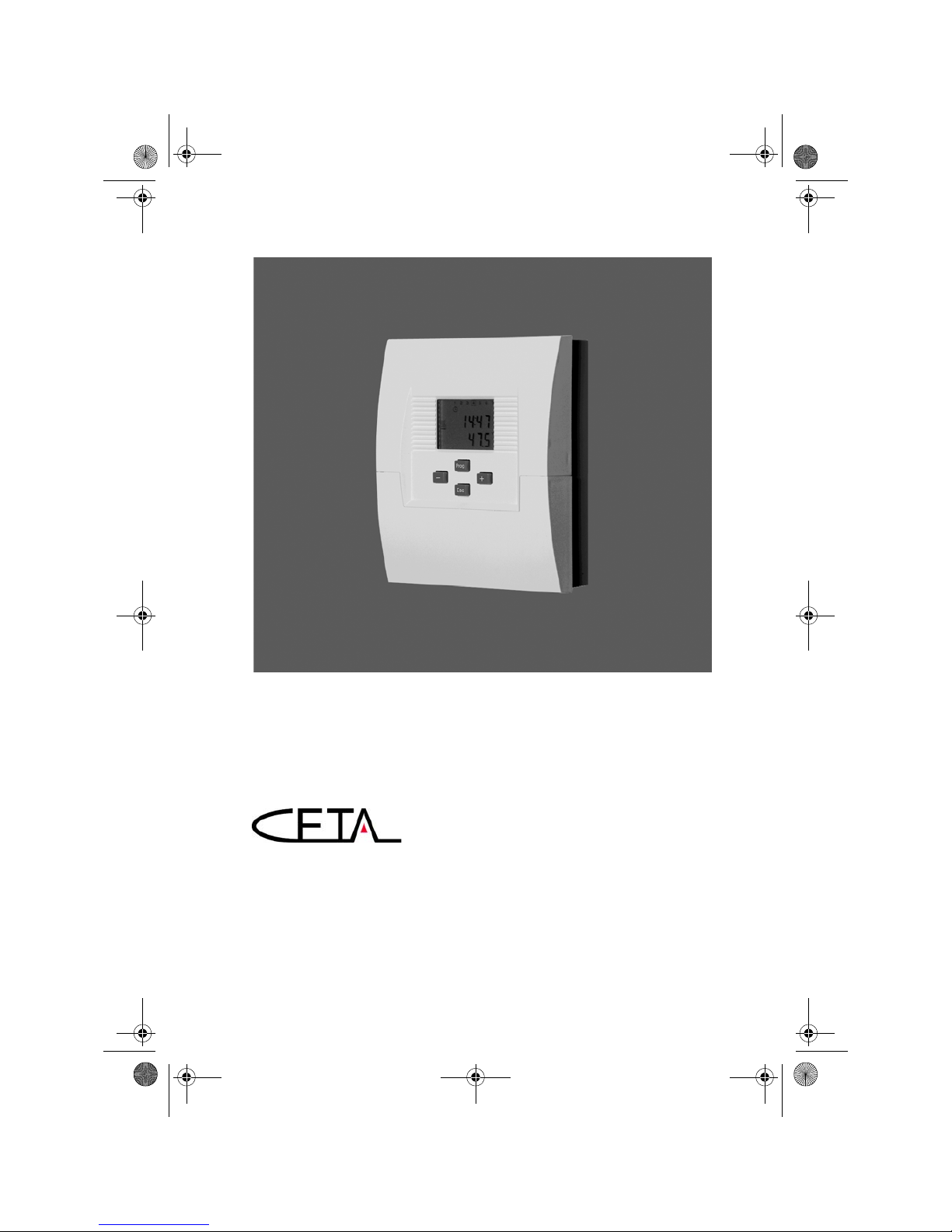
Operating manual
104
Heating circuit controller with burner control and DHW charging control
Version 0933-10
Art. 0450021002
BA_CETA104_EbV_EN_0450021002_0933-10.book Seite 1 Dienstag, 8. September 2009 10:20 10
Page 2
Contents
Scope of delivery ...............................................................................................................1
General ................................................................................................................................1
Intended use .....................................................................................................................1
Safety ..................................................................................................................................1
General key functions ...................................................................................................... 2
Version display (when starting)......................................................................................2
Basic display ..................................................................................................................... 3
Functions with direct access ..........................................................................................4
Menu level .........................................................................................................................5
Parameter description .....................................................................................................8
Installation ...................................................................................................................... 21
Connection diagram .......................................................................................................22
Fault clearance ................................................................................................................23
Sensor resistance values ..............................................................................................24
Declaration of conformity ..............................................................................................25
Technical data .................................................................................................................26
Liability .............................................................................................................................26
Disposal ...........................................................................................................................26
© Elektronikbau- und Vertriebs GmbH
Heisterner Weg 8 - 12
D-57299 Burbach
This document may not be reproduced nor disclosed to third parties, particularly competitors, in original
or copy form without our prior explicit consent. The document is subject to our proprietary rights and
copyrights.
BA_CETA104_EbV_EN_0450021002_0933-10.book Seite 2 Dienstag, 8. September 2009 10:20 10
Page 3
1
Scope of delivery
General
Systems with unmixed heating circuit are controlled via the heating circuit
controller. Required heating circuit temperature is determined in the flow,
depending on outside temperature.
The burner control adjusts the heat generator temperature via a switching contact
at the boiler immersion sensor.
The DHW control is accessing a DHW charging pump and controls the DHW
requirement in a DHW tank at the tank immersion sensor.
Intended use
The unit is manufactured in accordance with state of the art technology and
approved safety regulations. Nevertheless, using the unit can cause danger to the
user or third persons, or damage to the unit and other assets. The unit must be
used exclusively as heating circuit controller with burner control and DHW
charging control.
Safety
All electrical connections, safety measures and protections have to be carried out
by an authorised professional electrician according to the valid standards and VDEguidelines, as well as the local regulations. The electrical connection must be a
fixed connection according to VDE 0100.
Hazard symbols in this operating manual
1. 1x Central unit CETA 104
2. 1x Outside sensor AF200
3. 1x Boiler immersion sensor
KVT 20/2/6
4. 1x Tank immersion sensor
KVT 20/2/6
5. 8x Screw, plate 2.9x19 mm
6. 3x Screw assembly 4x35 mm
7. 3 x Plu g U6
8. 2 x Cable clamp
Hazard!
This symbol indicates information that warns of possible safety
risks or severe and fatal injuries!
BA_CETA104_EbV_EN_0450021002_0933-10.book Seite 1 Dienstag, 8. September 2009 10:20 10
Page 4
General key functions
2
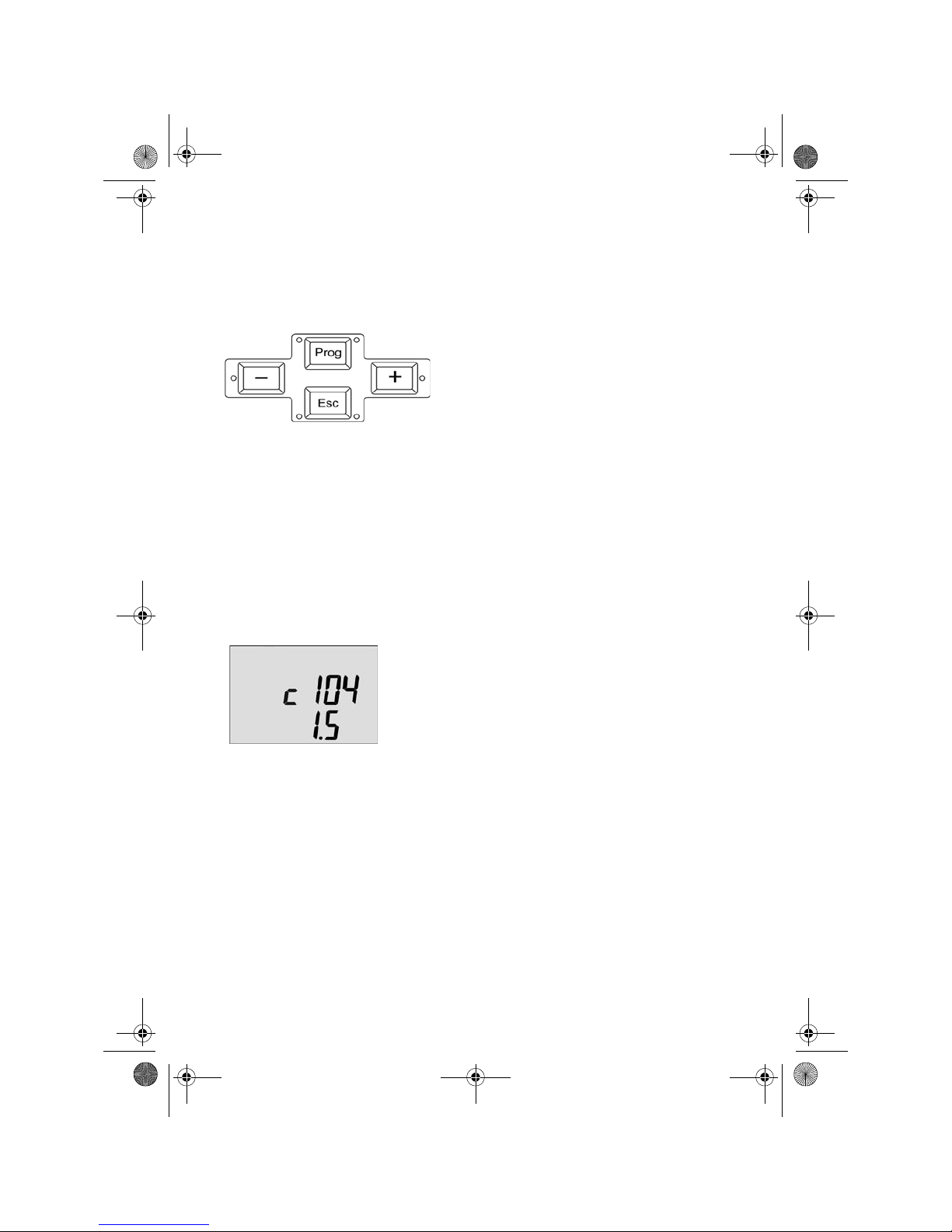
1. General key functions
Prog
•Change selected submenus
•Change (parameter) setting
•Save value
+ (Plus) or - (Minus)
•Change parameter
•Change menu item
Esc
•Exit setting
•Keep old value
•Select next higher menu level
Esc-Lang
•Return to basic display
2. Version display (when starting)
c 104= Type designation Ceta 104
1.5= Version display (due to update it can
differ from example shown)
BA_CETA104_EbV_EN_0450021002_0933-10.book Seite 2 Dienstag, 8. September 2009 10:20 10
Page 5
3
Basic display
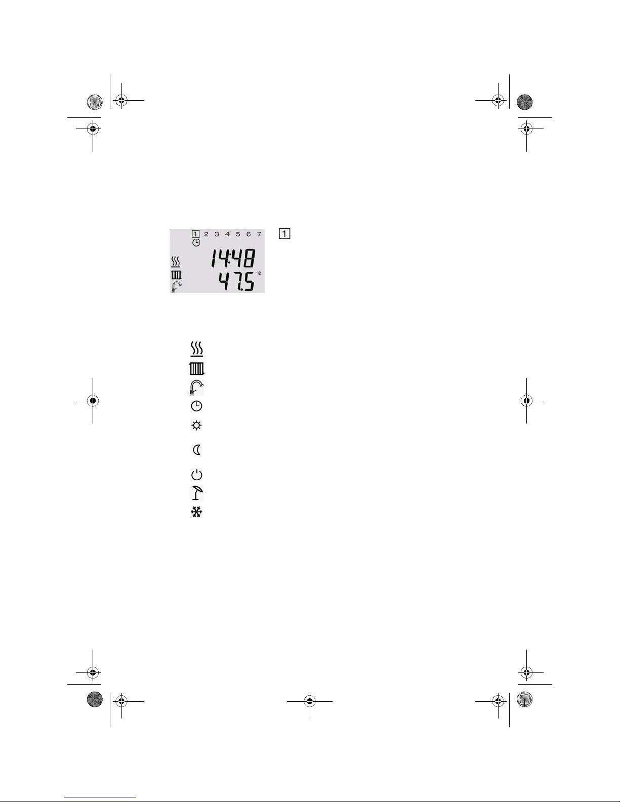
3. Basic display
Explanation of symbols
Display weekday
14:48 Display time
47.5°C Temperature F1 heat generator
Display heat generator in operation
Display pump function heating circuit
Display pump function tank loading
Automatic mode heating circuit after timer program I or II
Heating mode heating circuit
(Operating mode AUTOMATIC or HEATING)
Reduced mode heating circuit
(Operating mode AUTOMATIC or RED. HEATING)
Standby heating circuit
Summer switch-off heating circuit
Frost protection heating circuit
BA_CETA104_EbV_EN_0450021002_0933-10.book Seite 3 Dienstag, 8. September 2009 10:20 10
Page 6
Functions with direct access
4
4. Functions with direct access
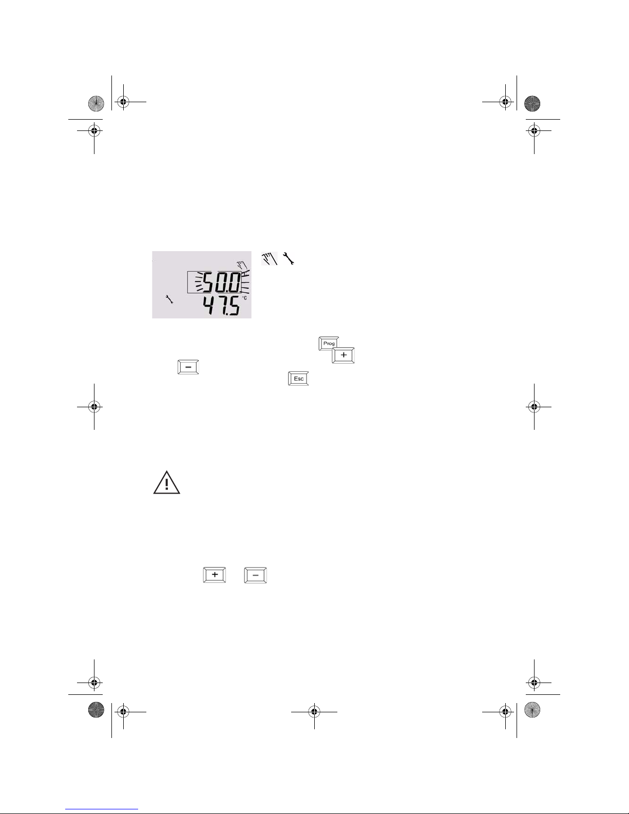
Manual operation
— Activate by pressing and holding button
— Change heat generator setpoint via buttons
and
— end function by pressing button
Adjustment room setpoint
Press buttons and in the basic display to directly set room day
temperature. Such a variation changes the parameter 06:02 (see parameter
description).
Controller is in manual mode
Function: Manual operation allows manual start-up of the system, e.g. to
perform emission measurement.
The heat generator adjusts the temperature to the set value
— The heating circuit pump runs continuously
— The DHW charging pump runs continuously
Caution!
This function shall only be used by an authorised
professional. Heating circuit temperatures are not monitored
during measurement of emission. Faulty operation or
unsupervised operation of this function may result in
damages to the heating system.
+
BA_CETA104_EbV_EN_0450021002_0933-10.book Seite 4 Dienstag, 8. September 2009 10:20 10
Page 7
5
Menu level
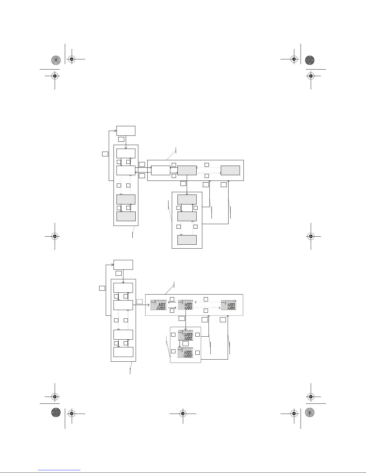
5. Menu level
Basic display
Prog
Esc
01
Menu 01
02
Menu 02
+
-
27
Calibration
28
Relay test
02:01
Parameter 01
02:02
Parameter 02
02:nn
Last parameter
+
-
+
-
+
-
+
-
Prog
Select menu level
Select parameters
Esc
Value1
Prog
Value 2
+
-
Value n
+
-
Set parameter value
Prog
Return
without
saving
Return
and save
Esc
General menu structure
Basic display
Prog
Esc
01
Info
02
Prog.
Time programs
+
-
27
Sensor
adj.
28
Relay test
+
-
+
-
+
-
+
-
Prog
Select menu level
Select menu level
Esc
HEZBEGINN
Prog
HEIZENDE
+
-
+
-
Set
parameter
value
Prog
Return
without
saving
Return
and
save
Prog
Menu structure time programs
BA_CETA104_EbV_EN_0450021002_0933-10.book Seite 5 Dienstag, 8. September 2009 10:20 10
Page 8
Menu level
6
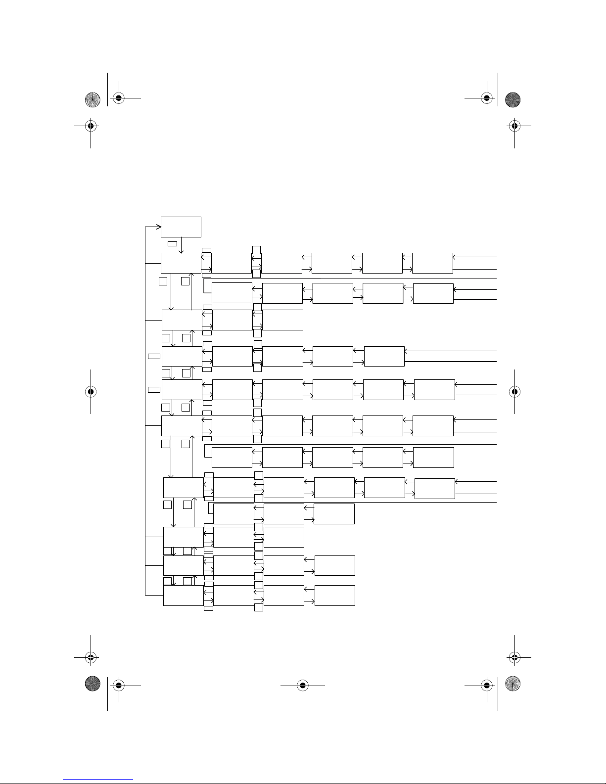
Overview of menu level
Basic display
01
Info
02
Time programs
06
03:01
Outdoor actual
03:02
Outdoor long-term
03:03
Outdoor min
03:04
Outdoor max
04:01
Temperature
heat generator
03:01
Code entry
03:02
AutoSet function
03:04
Building type
06:01 06:02 06:03
03
System
06:04
06:05
06:20
06:11
06:13
Room factor
06:14 06:15
07
07:01
07:02
07:03
07:04
07:05
07:14
07:11
07:12
26
26:01 26:02
Weekday
27
27:01
27:02 27:04
28
28:01 28:02
28:04
Esc
-
+
-
+
-
+
-
+
-
+
+
-
+
-
Prog
Esc
+
-
+
-
+
-
-
+
-
+
-
-
+
-
+
03:05
Climate zone
04:01
Function of
heat generator
04:02
Heat generator min.
temperature limit
04:03
Heat generator max.
temperature limit
04:04
04
Heat generator
Esc
+
-
04:05
+
-
X3
X3
X3
X3
X3
X3
X3
X5
X3
X3
X3
X3
X4
X3
X4
X3
X4
X3
X3
X3 X3 X3
Prog
Prog
Esc
Esc
Prog
Prog
Prog
Prog
Prog
Prog
Prog
Esc
Esc
Esc
Esc
Esc
05:03
Actual value
modulation depth
X5
05:04
Hydrau.press
X5
05:05
Flue gas
temperature
X5
06:01
Display
heating pump
06:04
Flow setpoint
See menu structure
time programs
See menu structure
time programs
Burner switching
differential
Minimum burner
run time
Heating circuit
Function Room day Room night
Operating mode Time program
Extended pump
running time
Room
thermostat function
Room frost
protection limit
Heat generator
parallel shift
DHW
Function DHW day
DHW night Operating mode
Time program
Temperature
parallel shift
Extended pump
running time
Priority mode
Time setting
Time
Sensor calibration
Calibration sensor 1
Calibration sensor 2
Calibration sensor 4
Relay test
Relay test 1
Relay test 2
Relay test 4
BA_CETA104_EbV_EN_0450021002_0933-10.book Seite 6 Dienstag, 8. September 2009 10:20 10
Page 9
7
Menu level
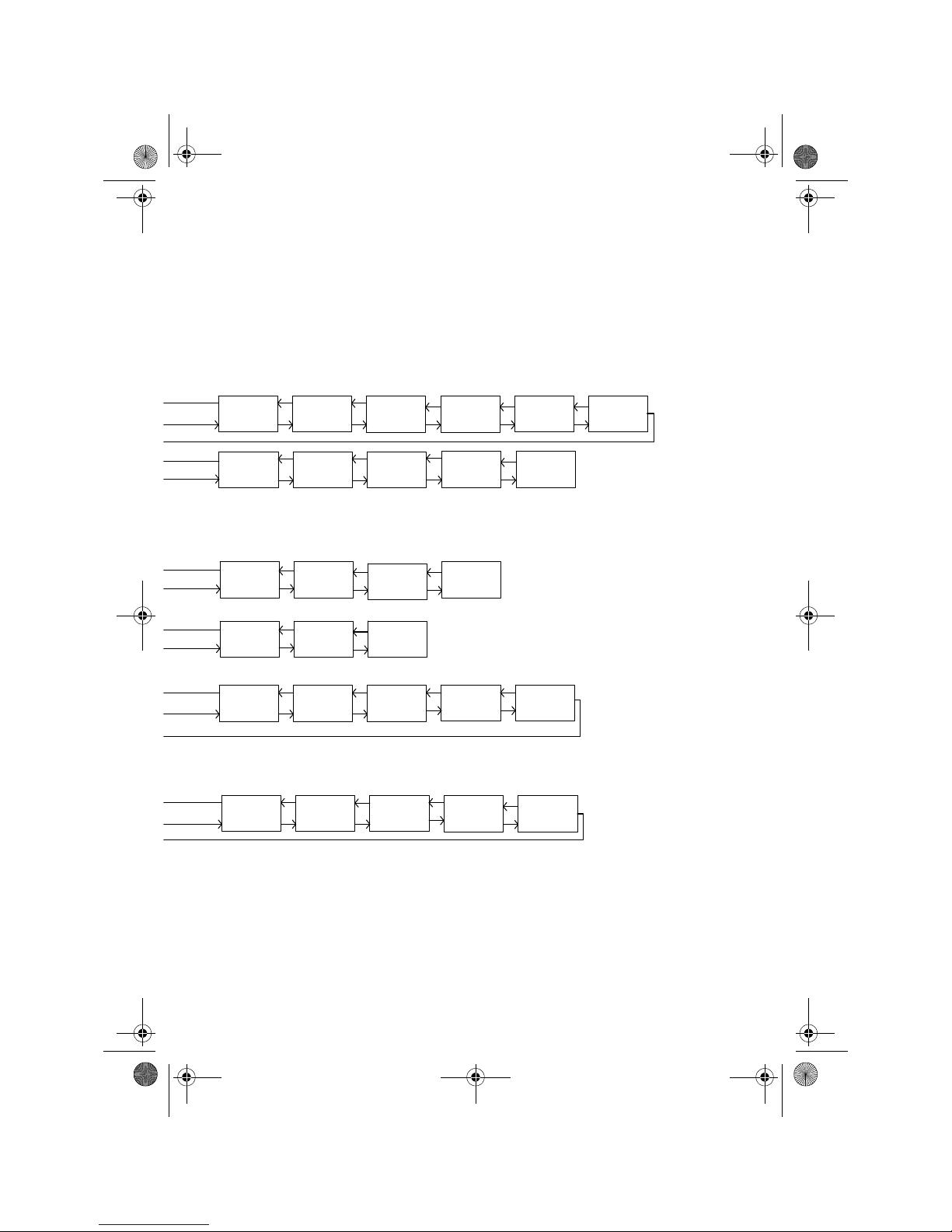
X2: Function only in bus connection
X3: Are hidden when activating code 03:09
X4: Only when connecting CETA RC
X5: Only in conjunction with heat generator connection via OpenTherm, and when
supported by heat generator
04:02
Setpoint heat
generator
04:03
Display status
heat generator
03:06
Time for
automatic exit
03:07
Anti-blocking
protection
03:09
Code heating
specialist
03:10
Reset
parameter
06:06
Type of reduced
operation
(ECO/RED)
06:07
Heating
curve/conductance
06:08
Heating system
(exponent)
06:09
System frost
protection
06:10
Summer switch-off
07:06
Legio.prot.(day)
07:07
Legio.protection
(time)
07:08
Legio.protection
(temperature)
07:09
Switching
differential
07:10
Maximum
temperature limit
04:06
Start-up protection
04:07
Start-up protection
switching differential
04:08
Reset counter
X3
X3
X3
X3
X3
X3
X3
X3 X3
X3 X3
X3 X3 X3
05:01
Temperature return
flow sensor
X5
05:02
Setpoint
modulation depth
X5
07:01
Display DHW
charging pump
07:02
DHW actual value
07:03
DHW setpoint
04:04
Starts heat
generator
04:05
Operating hours
heat generator
06:06
Room setpoint
X4
06:05
Room actual
X4
BA_CETA104_EbV_EN_0450021002_0933-10.book Seite 7 Dienstag, 8. September 2009 10:20 10
Page 10
Parameter description
8
6. Parameter description
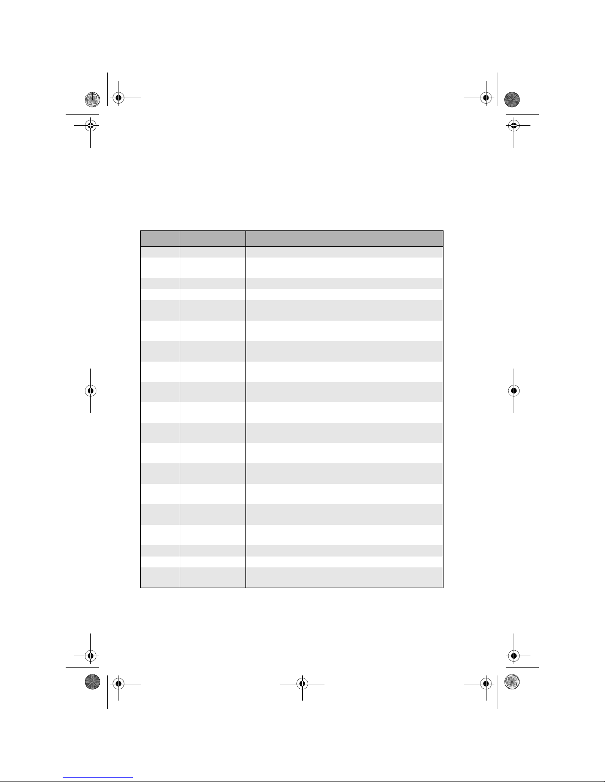
01 Information level
Display Designation Description
03:01 Outdoor actual Current outside temperature
03:02 Outdoor long-term Average long-term value of outside temperature. Depending on
set building type (03:04), the value is averaged longer or shorter.
03:03 Outdoor min Minimum outside temperature value (0.00 to 24.00 h)
03:04 Outdoor max Maximum outside temperature value (0.00 to 24.00 h)
04:01 Temperature heat
generator
Actual temperature on heat generator sensor
04:02 Setpoint heat
generator
Setpoint temperature for heat generator
04:03 Display status heat
generator
0: Heat generator outlet is switched off
1: Heat generator outlet is switched on
04:04 Starts
Heat generator
Number of heat generator starts
04:05 Operating hours
Heat generator
Number of heat generator operating hours
05:01 Temperature
Return flow sensor
Actual temperature heat generator return X5
05:02 Setpoint
Modulation depth
Setpoint heat generator-modulation depth (only if X5
system contains information)
05:03 Actual value
Modulation depth
Actual value heat generator-modulation depth (only if X5
system contains information)
05:04 Hydrau.press Water pressure in heating system in bar (only if X5
system contains information)
05:05 Flue gas
temperature
Flue gas temperature of heat generator (only if X5
system contains information)
06:01 Display heating
circuit pump
0: Heating circuit pump is switched off
1: Heating circuit pump is switched on
06:04 Flow heating circuit
setpoint
Flow setpoint temperature for heating circuit
06:05 Room actual Actual temperature in room X4
06:06 Room setpoint Room setpoint temperature for heating circuit
07:01 Display DHW
charging pump
0: Pump is switched off
1: Pump is switched on
BA_CETA104_EbV_EN_0450021002_0933-10.book Seite 8 Dienstag, 8. September 2009 10:20 10
Page 11
9
Parameter description
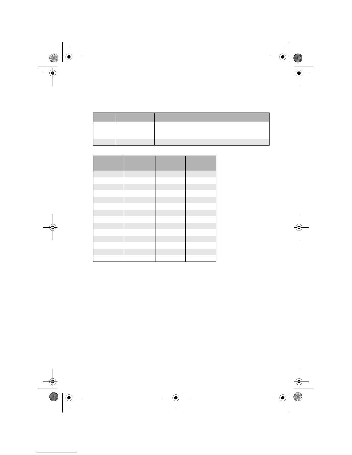
02 Time programs
Note: When switch-on and switch-off time are the same, cycle of operation is
switched off.
07:02 DHW actual value Sensor mode: Actual temperature on DHW sensor
Thermostat mode: 0 = Input open
1 = Input closed
07:03 DHW setpoint Setpoint temperature for DHW tank
Weekday
Cycle of
operation
Switch-on
time
Switch-off
time
1 I 06:00 22:00
1II12:0012:00
2 I 06:00 22:00
2II12:0012:00
3 I 06:00 22:00
3II12:0012:00
4 I 06:00 22:00
4II12:0012:00
5 I 06:00 22:00
5II12:0012:00
6 I 06:00 22:00
6II12:0012:00
7 I 06:00 22:00
7II12:0012:00
Display Designation Description
BA_CETA104_EbV_EN_0450021002_0933-10.book Seite 9 Dienstag, 8. September 2009 10:20 10
Page 12
Parameter description
10
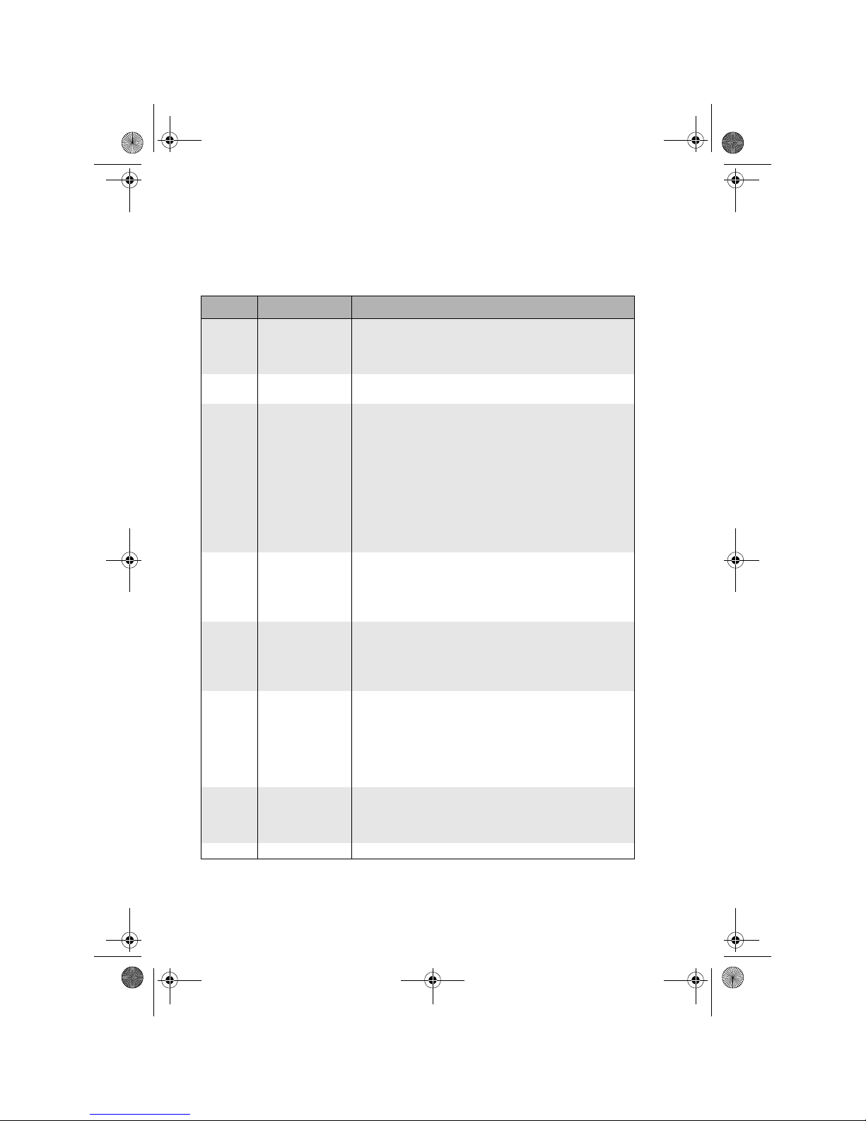
03 Parameter system
Display Designation Description
03:01 Code entry Setting range: 0 … 999
Factory s etti ng: 0
Function:
Show parameters marked with X3.
03:02 Automatic set
function
0=OFF, no automatic sensor detection X3
1=ON, automatic sensor detection
03:04 Building type Setting range: 1: Light construction (mean value over 6 X3
hours)
2: Medium construction
(mean value over 24 hours)
3: Heavy construction
(mean value over 72 hours)
Factory s etti ng: 2
Function:
This parameter considers the building type by adapting the
calculation of the outside temperature mean value according to
its setting.
03:05 Climate zone Setting range: -50 °C … 0 °C X3
Factory setting: -12 °C
Function:
The climate zone is the coldest outside temperature value to be
expected.
03:06 Automatic exit time Setting range: 0.5 ... 10 Min X3
Factory setting: 2 min
Function:
When unit is not operated during the set time, the display
returns to basic display.
03:07 Anti-blocking
protection
Setting range: 0 = OFF X3
1 = ON
Factory s etti ng: O FF
Function:
With this function activated, pump is switched on daily for ca. 20
seconds as protection against blocking during extended switchoff phases (> 24h).
03:09 Code heating
specialist
Setting range: 0 … 999
Factory s etti ng: 0
Function when setting is greater than 0:
Hide parameters marked with X3.
03:10 Total reset Reset to factory settings
BA_CETA104_EbV_EN_0450021002_0933-10.book Seite 10 Dienstag, 8. September 2009 10:20 10
Page 13
11
Parameter description
04 Parameters heat generator
Display Designation Description
04:01 Function of heat
generator
Setting range: 0 = OFF X3
1 = H-GEN single stage
2 = H-GEN OpenTherm
Fac to r y setti ng: 1
Function:
0: Control of a single-stage heat generator
via a relay output
1: Control of a heat generator with
standardised OpenTherm interface via
setpoint transfer
Note: only possible if OpenTherm logo
is available on CETA 104
04:02 Minimum
temperature limit HGEN*
Setting range: 5 °C … 95 °C X3
Factory setting: 38 °C
Function:
To protect the heat generator against aggressive condensate, the
minimum temperature limit specified by the manufacturer of the
heat generator must be set.
• Forced switch-on of DHW when value drops below limit
• Switch-off DHW at set value + burner switching differential
If there is no demand from heating system or DHW, the boiler
will be switched off. If the temperature in the heat generator
drops below the heat generator frost protection temperature of
+5°C, the burner will be switched on and the heat generator is
heated to the minimum temperature limit.
04:03 Maximum
temperature limit HGEN*
Setting range: 5 °C … 100 °C X3
Factory setting: 95 °C
Function:
• Forced switch-off of DHW when value is exceeded
• H-GEN is switched on again at set value – ½SD – 2K
04:04 Burner switching
differential (SD) *
Setting range: 2…30K X3, X5
Fac to r y setti ng: 6K
Function:
On multiple stage heat generators, the setpoint on heat
generator sensor is controlled by the burner switching
differential.
• Switch-on of heat generator at setpoint temperature – ½ SD
• Switch-off of heat generator at setpoint temperature + ½ SD
*
This function shall only be used by an authorised professional.
Incorrect settings can result in system damages.
BA_CETA104_EbV_EN_0450021002_0933-10.book Seite 11 Dienstag, 8. September 2009 10:20 10
Page 14
Parameter description
12
06 Parameter heating circuit
04:05 Minimum burner
run time
Setting range: 0…20 Min X3
Factory setting: 2 min
Function:
After starting the heat generator, at least the set time must
lapse before the heat generator is deactivated again.
Note: The maximum temperature limit takes priority
over this function.
04:06 Start-up protection Setting range: 5…95 °C X3
Factory setting: 36 °C
Function:
Start-up protection of heating circuits helps in preventing
condensate discharge when heating up in cold condition.
• Switch-off of heating circuits (unmixed circuits, mixed circuits,
DHW loading) when heat generator temperature drops below
the value
• Heating circuits are enabled when heat generator
temperature exceeds the value + start-up prot.switching
differential.
04:07 Start-up protection
switching
differential
Setting range: 2…20K X3
Factory s etti ng: 4 K
Function:
See description of parameter 04:06.
04:08 Reset counter Reset counter of heat generator starts and operating hours
Display Designation Description
06:01 Function Setting range: 0=OFF
1=Unmixed circuit
Factory s etti ng: 1
06:02 Room day Setting range: 5 … 30 °C
Factory setting: 20 °C
Function:
The set temperature is the room setpoint during active cycles of
operation in AUTOMATIC mode and during HEATING mode.
06:03 Room night Setting range: 5 … 30 °C
Factory setting: 16 °C
Function:
The set temperature is the room setpoint between the cycles of
operation in AUTOMATIC mode and during RED. HEATING mode.
Display Designation Description
BA_CETA104_EbV_EN_0450021002_0933-10.book Seite 12 Dienstag, 8. September 2009 10:20 10
Page 15
13
Parameter description
06:04 Operating mode Setting range: 1: Automatic
2: Heating
3: Red. heating
4: Standby
Fac to r y setti ng: 1
Function:
Automatic: Heating circuit operates in Heating or
Red. heating mode according to the time
program assigned under 06:05
Heating: Heating circuit operates continuously
according to set room day temp. (06:02)
Red. heating: Heating circuit operates continuously
according to set room night temperature
(06:03) under consideration of 06:06
Standby: Frost-protected switch-off of heating circuit
06:05 Time program Setting range: 1: Time program 1
2: Time program 2
3: Time program 1 and 2
Fac to r y setti ng: 1
Function:
Depending on the setting, the heating circuit operates according
to time program 1, 2 or both, as set in menutree 02 (time
programs).
06:06 Type of reduced
operation (ECO/RED)
Setting range: 0: ECO
1: RED
Fac to r y setti ng: 0
Function:
The settings are effective in Reduced operating mode.
ECO: Frost-protected switch-off mode
RED: Reduced mode
Display Designation Description
BA_CETA104_EbV_EN_0450021002_0933-10.book Seite 13 Dienstag, 8. September 2009 10:20 10
Page 16
Parameter description
14
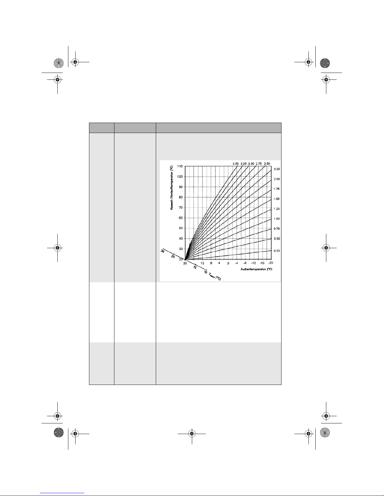
06:07 Heating curve/
conductance
Setting range: 0.05 … 3.50
Factory s etti ng: 1 .5 0
Function:
Determines the heating curve for the heating circuit.
06:08 Heating system
(exponent)
Setting range: 1.00…10.00 X3
Factory s etti ng: 1.30
Function:
Curvature of heating circuit's heating curve.
Recommendation: 1.10: Floor or other
panel heating systems
1.30: Radiator heating
2.00: Convector and baseboard heating
>3.00: General ventilator applications with
high start temperatures
06:09 Frost protection Setting range: OFF (----) X3
-50 °C ... +10 °C
Factory setting: 3 °C
Function:
To keep the heating system from freezing in switch-off mode, the
controller is equipped with electronic frost protection.
Caution: Faulty operation can result in damages to building!
Display Designation Description
BA_CETA104_EbV_EN_0450021002_0933-10.book Seite 14 Dienstag, 8. September 2009 10:20 10
Page 17
15
Parameter description
06:10 Summer switch-off Setting range: OFF (----) X3
10 °C ... 30 °C
Factory setting: 20 °C
Function:
Switch-off of heating operation at outside temperatures above
the desired outside temperature.
06:11 Extended pump
running time
Setting range: 0.0…60.0 Min X3
Fac to r y setti ng: 5 m i n
Function:
This function determines extended run time of heating circuit
pump after heating circuit is switched off by time programs.
06:13 Room factor Setting range: 0…500% X3, X4
Fac to r y setti ng: 100%
Function:
This function determines to what extent a deviation of the room
temperature from the setpoint affects the control of boiler flow
temperature.
Corrected room setpoint = set room setpoint - (deviation x room
factor) / 100
06:14 Room thermostat
function
Setting range: Off (----) X3, X4
0.5 … 5K
Factory setting: Off (---)
Function:
This function determines a room temperature limit; if limit is
exceeded, heating is turned off.
06:15 Room frost
protection limit
Setting range: 5…30 °C X3, X4
Factory setting: 10 °C
Function:
This function determines the room setpoint of the corresponding
heating circuit during switch-off mode with frost protection
activated.
06:20 Heat generator
parallel shift
Setting range: 0…20K X3
Fac to r y setti ng: 0K
Function:
The demand value of the heating circuit, plus the shift value, is
transmitted to the heat generator.
Display Designation Description
BA_CETA104_EbV_EN_0450021002_0933-10.book Seite 15 Dienstag, 8. September 2009 10:20 10
Page 18
Parameter description
16
07 DHW parameters
Display Designation Description
07:01 Function Setting range: 0 = OFF
1 = Sensor mode
2 = Thermostat mode
3 = Automatic mode DHW
Factory s etti ng: 1
Function:
Sensor mode: Control via temperature sensor in
domestic hot water tank
Thermostat mode: Alternatively, DHW heating can also be
controlled via a mechanical temperature
controller (thermostat switching contact)
In this case a DHW thermostat
is connected instead of a DHW sensor
and set to the desired DHW
setpoint. If the contact is closed, DHW
loading takes place at the set DHW
maximum temperature until the contact is
opened again.
07:02 DHW day Setting range: 5 … 65 °C
Factory setting: 50 °C
Function:
The set temperature is the DHW setpoint during active cycles of
operation in AUTOMATIC mode and during HEATING mode.
07:03 DHW night Setting range: 5 … 65 °C
Factory setting: 20 °C
Function:
The set temperature is the DHW setpoint between the cycles of
operation in AUTOMATIC mode and during RED. HEATING mode.
BA_CETA104_EbV_EN_0450021002_0933-10.book Seite 16 Dienstag, 8. September 2009 10:20 10
Page 19
17
Parameter description
07:04 Operating mode Setting range: 1: Automatic
2: Heating
3: Red. heating
4: Standby
Fac to r y setti ng: 1
Function:
Automatic: DHW operates in Heating or
Red. heating mode according to the time
program assigned under 07:05
Heating: DHW operates continuously according to set
DHW day temperature (07:02)
Red. heating: DHW operates continuously according to set
room night temp. (07:03)
Standby: Frost-protected switch-off of DHW
07:05 Time program Setting range: 1: Time program 1
2: Time program 2
3: Time program 1 and 2
Fac to r y setti ng: 1
Function:
Depending on the setting, DHW operates according to time
program 1, 2 or both, as set in menu tree 02 (time programs).
07:06 Legionella
protection
(day)
Setting range: 0: OFF X3
1 … 7: Monday … Sunday
8: All
Fac to r y setti ng: 1
Function:
A legionella protection function can be activated to eliminate the
legionella germs in the tank. In order to completely kill all
germs, the Legionella protection temperature should be set at
least at 60-65 °C. The legionella protection function is activated
for 1 hour.
OFF: Function is not active
1 … 7: Function is performed once a week on the set
weekday
All: Function is performed each weekday
Display Designation Description
BA_CETA104_EbV_EN_0450021002_0933-10.book Seite 17 Dienstag, 8. September 2009 10:20 10
Page 20
Parameter description
18
07:07 Legionella
protection (time)
Setting range: 00:00 … 23:00 o'clock X3
Factory setting: 02:00 o'clock
Function:
This value is used to set the time at which the legionella
protection function is to be started on the set weekday (see
07:06).
07:08 Legionella
Protection
(temperature)
Setting range: 10…65 °C X3
Factory setting: 60 °C
Function:
This value is used to specify setpoint temperature for legionella
protection function (see 07:06).
07:09 Switching
differential
Setting range: 2 … 20K X3
Factory s etti ng: 5 K
Function:
To prevent frequent loading of the DHW tank, the DHW setpoint
temperature is adjusted under consideration of a switching
differential.
• Activation of DHW loading at setpoint temperature – ½
switching differential
• Termination of DHW loading at setpoint temperature + ½
switching differential
07:10 Maximum
temperature limit
Setting range: 20 … 80 °C X3
Factory setting: 65 °C
Function:
This function serves as protection of the DHW tank.
Irrespective of parameter settings 07:02, 07:03 and 07:08, at
most the set value will be adjusted.
If exceeded, the charging pump is switched off immediately.
ATTENTION: Observe operating instructions of DHW tank
before making any changes. Excessive maximum temperatures
can result in damages on DHW tank.
07:11 Exceeded load
temperature
Setting range: 0 … 20K X3
Factory s etti ng: 1 0K
Function:
This function determines the lead value for the tank load
temperature through the heat generator, compared to the set
DHW setpoint.
Heat generator setpoint = DHW setpoint +
Exceeded load temperature
Display Designation Description
BA_CETA104_EbV_EN_0450021002_0933-10.book Seite 18 Dienstag, 8. September 2009 10:20 10
Page 21
19
Parameter description
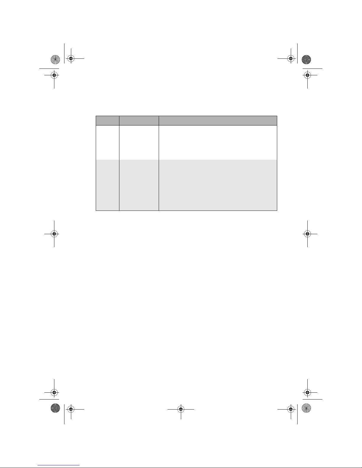
07:12 Extended pump
running time
Setting range: 0…60 Min X3
Fac to r y setti ng: 5 m i n
Function:
After switching off the heat generator, the tank loading pump is
stopped after a time delay to prevent a safety switch-off in case
of high temperatures.
07:14 Priority mode DHW Setting range: 0: Parallel mode X3
1: Priority mode
Fac to r y setti ng: 1
Function:
Parallel mode: During tank loading the heating circuits
remain operative
Priority mode: During tank loading the heating circuits are
shut down. They are restarted after the
extended running time of the pump (07:12).
Display Designation Description
BA_CETA104_EbV_EN_0450021002_0933-10.book Seite 19 Dienstag, 8. September 2009 10:20 10
Page 22
Parameter description
20
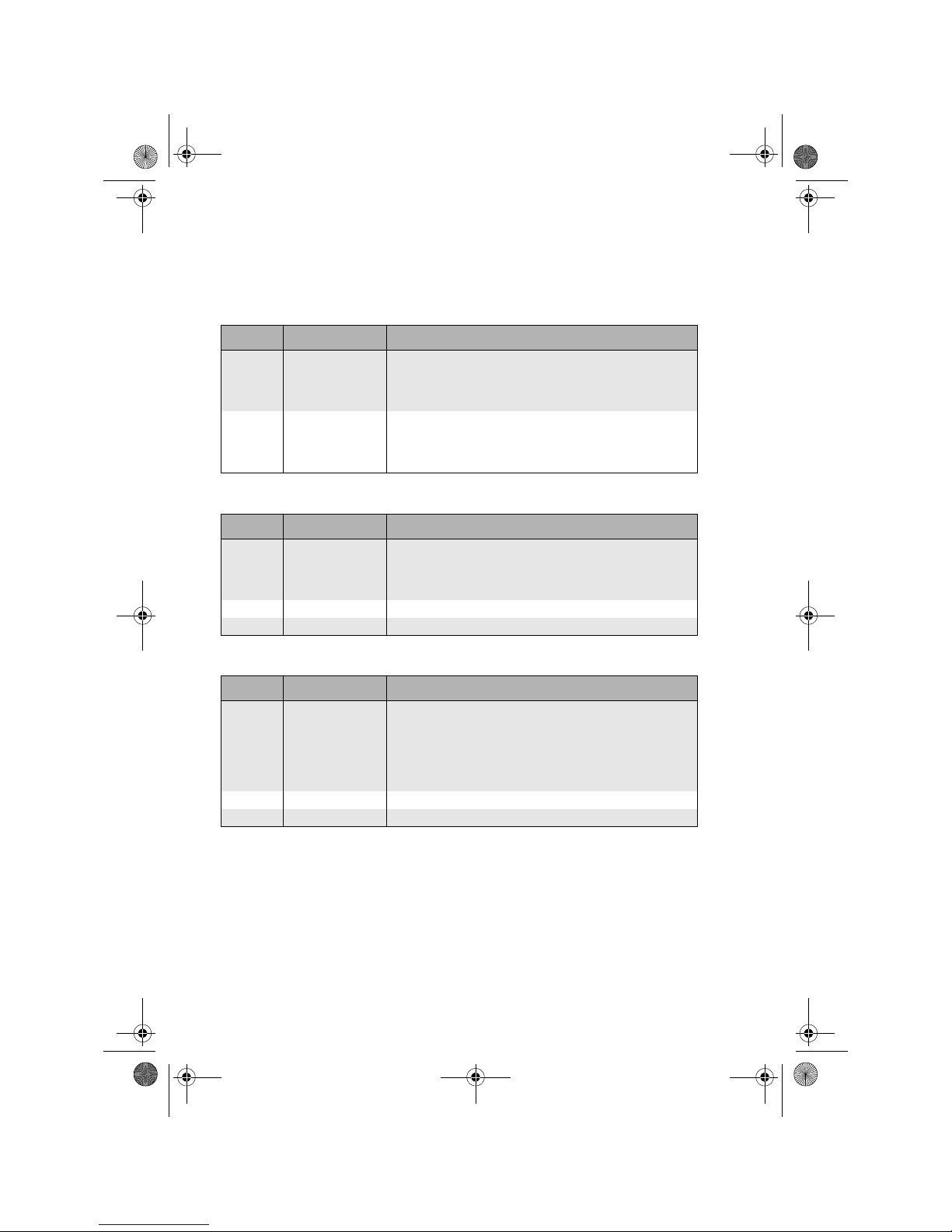
26 Time setting
27 Sensor calibration
28 Relay test
Display Designation Description
26:01 Time Setting range: 00:00 ... 23:59
Factory s etti ng: Curren t ti me
Function:
Setting of current time.
26:02 Weekday Setting range: 1 ... 7
Factory setting: Current weekday
Function:
Setting of current weekday.
Display Designation Description
27:01 Calibration F1 Setting range: -5K ... +5K
Factory s etti ng: 0K
Function:
Correction of measured sensor value at input of heat generator F1
27:02 Calibration F2 See 27:01 on input DHW sensor F2
27:04 Calibration F4 See 27:01 on input outside sensor F4
Display Designation Description
28:01 Te st o ut p u t 1 Setting range: -0 = OFF
1 = ON
Factory s etti ng: 0
Function:
By changing the value, the output switches heat circuit pump on
and off (test function), independent of function.
28:02 Test output 2 See 28:01 for output DHW charging pump
28:04 Te st o ut pu t 4 See 28:01 for output DHW charging pump
BA_CETA104_EbV_EN_0450021002_0933-10.book Seite 20 Dienstag, 8. September 2009 10:20 10
Page 23
21
Mounting
7. Mo unting
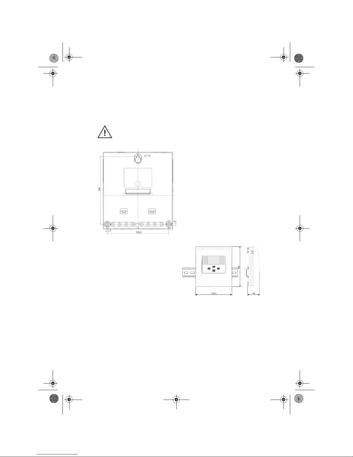
Drilling pattern for wall fastening
Rail mount
Hazard!
Mounting must be performed by an authorised professional electrician!
Ensure that unit is de-energised before opening it!
1. Remove terminal area cover from
casing.
2. For mounting, first put a screw
into the wall.
3. Hang controller into the opening.
4. Use controller as template for the
other screw holes.
1. Insert mounting feet into rail
mount opening.
2. Lock hook in place by pushing
down.
BA_CETA104_EbV_EN_0450021002_0933-10.book Seite 21 Dienstag, 8. September 2009 10:20 10
Page 24
Connection diagram
22
8. Connection diagram
Hazard!
Connection must be performed by an authorised professional
electrician! Ensure that unit is de-energised before opening it!
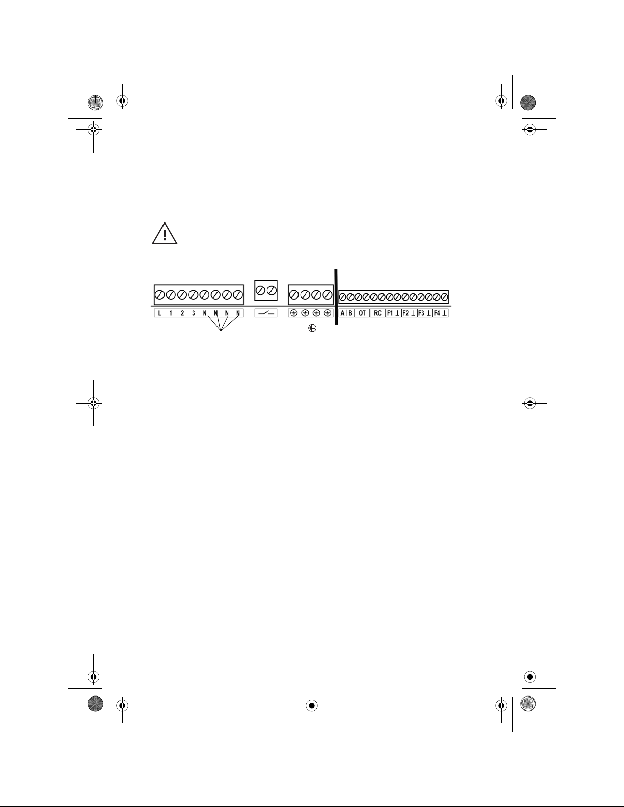
Low voltage connections
L=Phase 230V mains
1=L1 (230V) pump connection unmixed circuit pump (DKP)
2=L1 (230V) pump connection DHW charging pump (SLP)
Connection without function
N=Neutral 230V mains, pumps
Connection H-GEN (isolated)
=Earthing
Bus connections for networking
Connection OpenTherm
RC=Connection CETA RC (option)
F1=Sensor heat generator (KVT20/2/6)
F2=Sensor DHW tank (KVT20/2/6)
Connection without function
F4=Sensor outside temperature (AF200)
230V connections
BA_CETA104_EbV_EN_0450021002_0933-10.book Seite 22 Dienstag, 8. September 2009 10:20 10
Page 25
23
Fault clearance
9. Fault clearance
To allow an accurate diagnosis in case of malfunction, the unit is equipped with
a fault display system. The faults are shown on the basic display of the unit in
form of an error code.
Fault overview:
Fault code Cause Repair
11-0 Interruption sensor F1 Check cable and plug connection,
replace if necessary
11-1 Short circuit sensor F1 Replace tank sensor
12-0 Interruption sensor F2 See 11-0
12-1 Short circuit sensor F2 See 11-1
13-0 Interruption sensor F3 See 11-0
13-1 Short circuit sensor F3 See 11-1
14-0 Interruption sensor F4 See 11-0
14-1 Short circuit sensor F4 See 11-1
71-6 Data bus OpenTherm
no signal (terminal OT)
Repair malfunction on data bus to
heat generator
72-6 Data bus CETA R C n o signal (termi na l
RC)
Repair malfunction on data bus to
room unit CETA RC
73-2 Unit bus address collision (Terminal
AB)
Set controls of the same type to
different bus addresses (parameter
03:03)
73-6, 74-0 to 74-9 Unit bus error communication
(Terminal AB)
Check bus connection between the
units
5-00 General errors on heat generator
(only for OpenTherm)
Purely display function in CETA
system, troubleshooting on heat
generator
5-00 Locking error on heat generator (only
for OpenTherm)
Only display function in CETA system,
troubleshooting on heat generator
6-00 Blocking error on heat generator
(only for OpenTherm)
Purely display function in CETA
system, troubleshooting on heat
generator
BA_CETA104_EbV_EN_0450021002_0933-10.book Seite 23 Dienstag, 8. September 2009 10:20 10
Page 26
Sensor resistance values
24
10. Sensor resistance values
Depending on temperature:
PT1000 KVT20/2/6, AF200
T (°C) R (kOhm) T (°C) R (kOhm)
40
50
60
70
80
90
100
110
120
130
140
150
160
170
180
190
200
210
220
230
240
250
1.155
1.194
1.232
1.271
1.309
1.347
1.385
1.423
1.461
1.498
1.536
1.573
1.611
1.648
1.685
1.722
1.758
1.795
1.832
1.868
1.905
1.941
10
12
14
16
18
20
25
30
35
40
45
50
55
60
65
70
75
80
85
90
95
100
1.783
1.812
1.840
1.869
1.898
1.928
2.002
2.078
2.155
2.234
2.314
2.395
2.478
2.563
2.648
2.735
2.824
2.914
3.005
3.098
3.192
3.287
BA_CETA104_EbV_EN_0450021002_0933-10.book Seite 24 Dienstag, 8. September 2009 10:20 10
Page 27
25
Declaration of conformity
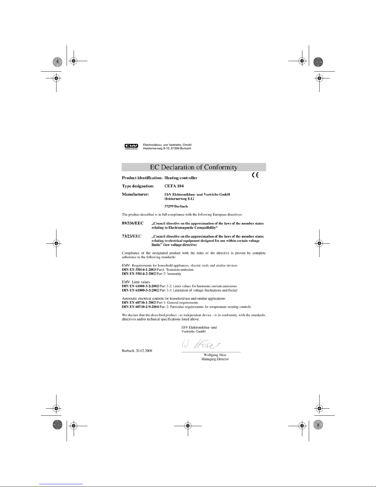
11. Declaration of conformity
BA_CETA104_EbV_EN_0450021002_0933-10.book Seite 25 Dienstag, 8. September 2009 10:20 10
Page 28
Technical Data
26
12. Technical Data
13. Liability
Our general terms and conditions of business are generally applicable. Any liability
claims based on failure to observe operating manual as well as safety instructions
contained therein, are excluded. Subject to technical modifications.
14. Disposal
Dispose of all replaced parts, and eventually the controller itself, in an
environmentally sound manner in compliance with applicable statutory
regulations of the corresponding country.
Mains voltage: 230V +6%/ -10%
Rated frequency: 50...60Hz
Power input: max. 2.1VA
Fuse: 6.3A
Output relay contact load: 2 (2)A
Ambient temperature: -10...+50 °C
Storage temperature: -25...+80 °C
Degree of protection: IP 30
Protection class according to EN 60730: II
CE compliance: 89/336/EEC
Casing dimensions: 145.5 x 161 x 48 mm (W x H x D)
Casing material: ABS V0
Weight: 420g
Mains connection technology:
Screw terminals 1.5 mm
2
Sensor connection technology:
Screw terminals 1.0 mm
2
Company stamp:
BA_CETA104_EbV_EN_0450021002_0933-10.book Seite 26 Dienstag, 8. September 2009 10:20 10
 Loading...