

Page 1
SC101
Sound level meter
User’s Manual
M_SC101_v0017_20100719_ENG
Page 2

Page 3

SC101
User’s Manual
ENGLISH
CONTENTS
1. GENERAL DESCRIPTION ..................................................................................................5
1.1 Operating modes and functions ......................................................................................5
1.2 Main features of the SC101 ............................................................................................6
1.3 Description of the SC101 ................................................................................................7
1.4 Screen and use of the keypad ........................................................................................9
2. OPERATING THE SC101..................................................................................................12
2.1 First steps .....................................................................................................................12
2.1.1 Equipment and documents .....................................................................................12
2.1.2 SC101 power supply...............................................................................................12
2.1.3 Connecting and disconnecting the preamplifier, using the extension cable and
outdoor kit ........................................................................................................................13
2.2 Starting a measurement................................................................................................15
2.2.1 Starting up the SC101 ............................................................................................15
2.2.2 Main menu of the SC101: Selecting applications and settings...............................16
2.2.3 Checking the SC101...............................................................................................17
2.3 Saturation......................................................................................................................18
2.4 Measuring with the sound level meter application ........................................................18
2.4.1 Starting a measurement .........................................................................................19
2.5 Measuring with the vehicle application..........................................................................20
2.5.1 Starting a measurement .........................................................................................20
2.5.2 Background noise measurement ............................................................................21
2.5.3 L
2.6 Measuring with the leisure and community application (correction by area).................22
2.6.1 Starting a measurement .........................................................................................22
measurement ................................................................................................21
AFmax
2.6.2 Background noise measurement (optional) ............................................................23
2.6.3 L
2.7 Measuring with the leisure and community application (correction by points) ..............25
2.7.1 Starting a measurement .........................................................................................25
2.7.2 Measurement without applying background noise correction.................................26
2.7.3 Measuring with background noise correction .........................................................27
2.8 Measuring with the occupational hazard application.....................................................28
2.8.1 Starting a measurement .........................................................................................28
2.8.2 Projection time ........................................................................................................29
and L’At measurement ........................................................................................24
At
1
Page 4

2.9 Measuring with the machinery application: sound pressure level.................................30
2.9.1 Starting a measurement .........................................................................................30
2.9.2 Background noise measurement ............................................................................31
2.9.3 Obtaining L
2.9.4 K
1A
and K
and L
pA
corrections............................................................................................32
3A
levels.................................................................................31
Cpeak
2.10 Measuring with the machinery application: sound power level ...................................33
2.10.1 Starting a measurement .......................................................................................33
2.10.2 Measuring the sound pressure level at several points..........................................34
2.10.3 Background noise measurement ..........................................................................34
2.10.4 K
1A
and K
corrections Surface area S.................................................................35
2A
2.11 Sensitivity setting ........................................................................................................36
2.12 Contrast setting...........................................................................................................37
2.13 Switching off the SC101.............................................................................................. 37
2.14 Tips and warnings.......................................................................................................37
2.15 Tips for taking measurements.....................................................................................38
3. VIEWING DATA ON A PC.................................................................................................38
4. TECHNICAL SPECIFICATIONS .......................................................................................39
4.1 Measurement range......................................................................................................39
4.2 Detector - Functions LF and LS......................................................................................41
4.3 Peak detector – Lpeak function.....................................................................................41
4.4 Averager – Lt function...................................................................................................41
4.5 Clock features ...............................................................................................................41
4.6 Frequency weighting.....................................................................................................42
4.7 Microphone ...................................................................................................................42
4.8 Directivity ......................................................................................................................44
4.9 Effect of the accessories on the microphone ................................................................44
4.10 Reference conditions ..................................................................................................45
4.11 Preheating time...........................................................................................................46
4.12 Influence of temperature .............................................................................................46
4.13 Influence of humidity ...................................................................................................46
4.14 Electromagnetic compatibility......................................................................................46
4.15 Influence of vibration...................................................................................................47
4.16 Batteries and external power supply...........................................................................47
4.17 Dimensions and weight...............................................................................................47
4.18 Preamplifier connector ................................................................................................47
4.19 Calibration...................................................................................................................48
4.20 Standards....................................................................................................................48
2
Page 5

SC101
User’s Manual
4.21 Notes...........................................................................................................................49
4.22 Accessories.................................................................................................................49
5. ANNEX A: Functions........................................................................................................50
5.1 Function summary chart................................................................................................50
5.1.1 Sound level meter application functions .................................................................50
5.1.2 Vehicle application functions ..................................................................................50
Functions measured............................................................................................................50
Grid functions......................................................................................................................50
5.1.3 Leisure and community application functions (area and points).............................51
Functions measured............................................................................................................51
Grid functions (area) ...........................................................................................................51
Grid functions (points).........................................................................................................51
Settable parameters............................................................................................................52
5.1.4 Occupational hazard application functions ............................................................. 52
Functions measured............................................................................................................52
Grid functions......................................................................................................................52
Settable parameters............................................................................................................52
5.1.5 Machinery application functions: sound pressure level ..........................................53
Functions measured............................................................................................................53
Grid functions......................................................................................................................53
Settable parameters............................................................................................................53
5.1.6 Machinery application functions: sound power level...............................................53
Functions measured............................................................................................................53
Form functions ....................................................................................................................54
Settable parameters............................................................................................................54
5.2 Function definition.........................................................................................................55
5.2.1 Sound pressure level with fast and slow time weighting.........................................55
5.2.2 Peak sound pressure level .....................................................................................55
5.2.3 Equivalent continuous sound pressure level ..........................................................55
5.2.4 Equivalent daily exposure level ..............................................................................56
3
Page 6

6. APPENDIX B: Vehicle noise ............................................................................................57
7. APPENDIX C: Leisure and community...........................................................................60
8. APPENDIX D: Occupational hazards..............................................................................61
9. APPENDIX E: Machinery; sound pressure level ...........................................................63
10. APPENDIX F: Machinery sound power level ...............................................................66
11. APPENDIX G: Grids........................................................................................................71
4
Page 7

SC101
User’s Manual
1. GENERAL DESCRIPTION
The SC101 is more than a mere sound measurement instrument. Not only does it allow the
necessary measurements to be taken, like other devices, it also guides the user through the
measurement process step-by-step. It is an effective and convenient device with
measurement protocols, offering the choice between conventional sound level meter
operation and measurements involving machinery, occupational hazards and others, aimed
at drawing up official reports in compliance with applicable regulations.
The SC101 is a class 1 integrating sound level meter in accordance with international
standard IEC 61672-1, its European counterpart EN 61672-1:2003 and its Spanish
counterpart UNE 61672-1:2005. Furthermore, it complies with standards IEC 60651 and
IEC 60804 type 1, as well as with American standards ANSI S1.4 and S1.43.
1.1 Operating modes and functions
The SC101 is suitable for various applications:
• The CONVENTIONAL SOUND LEVEL METER
application simultaneously measures the
following functions:
LAt, L
L
, L
A1”
Ct
C1”
Equivalent continuous sound pressure level of the measurement time
with A and C frequency weighting
Equivalent continuous sound pressure level, with consecutive integration
time of 1 second and A and C frequency weighting
L
Cpeak
LAF, LAS
Peak sound pressure level with C frequency weighting
Sound pressure level with ‘S’ and ‘F’ time averaging and maximum and
minimum values during measurement time with A frequency weighting.
LCF
* A definition of each of the measured functions can be found in appendix A.
The SC101 also has applications dedicated exclusively to providing a step-by-step guide
through the protocols for the purpose of performing the following acoustic evaluations:
C weighted sound pressure level with ‘F’ time averaging and its
maximum and minimum values during the measurement time.
• VEHICLES
: Determining the sound level (L
) generated by the exhaust system of
AFmax
motor vehicles: cars, public transport vehicles, goods vehicles, motorcycles, mopeds,
three-wheeled vehicles, all-terrain bikes and quads. Test with vehicle stopped in
accordance with Directives 70/157/EEC, 78/1015/EEC and 97/24/EC Chap. 9.
• LEISURE AND COMMUNITY (correction by area)
: Determining the emission and
immission sound levels of businesses and residents in accordance with the various
municipal bylaws in which the specified procedure consists of averaging the background
noise and the activity noise, in order to subsequently apply the background noise
correction.
• LEISURE AND COMMUNITY (correction by points)
: Determining the emission and
immission sound levels of businesses and residents in accordance with the various
municipal bylaws in which the specified procedure consists of measuring the background
noise and the activity noise in each of the points to be assessed, and corrected with its
corresponding background noise.
5
Page 8

• OCCUPATIONAL HAZARDS: Determining the sound levels (L
exposure in the workplace. In accordance with ISO 9612, determination based on tasks,
jobs or working days.
• MACHINERY – SOUND PRESSURE
by machines and equipment at the workplace. In accordance with Directives 2005/88/EC
and 2006/42/EC and ISO 11202.
• MACHINERY – SOUND POWER
sources. In accordance with Directives 2005/88/EC and 2006/42/EC and ISO 3746.
: Determining the noise levels (LpA, L
: Determining the sound power level (LWA) of noise
EX,8h
, L
) of noise
Cpeak
Cpeak
) emitted
1.2 Main features of the SC101
The SC101 is the first sound level meter designed to meet the needs of its users; a userfriendly sound level meter, which can perform acoustic measurements in a quick, convenient
and straightforward manner.
The SC101 includes the following main features:
• The SC101 is a sound level meter with measurement protocols: it includes applications for
guiding the user step-by-step through the measurement protocols (measurements, tests
and calculations) required to obtain the end result on site. It can also be used as a
conventional sound level meter.
• The SC101 has a menu structure with visual, intuitive options
need to configure the language, since the icons are easy to identify and recognise.
• The membrane keypad of the SC101 is designed to be completely flat, to avoid affecting
the excellent acoustic response rate of the device. Moreover, it has a single on/off button
and a simple interface with three soft-key buttons
• The large, high-resolution 3.2” graphic display
according to each application, as well as the partial and final results. Throughout the
measurement process, the values of the measured functions fill in the boxes on the grid
while simultaneously calculating the partial results and the parameters to perform the
tests, ultimately presenting the final results.
• The SC101 has a single measurement range
starting the measurement, and it is therefore independent from the type of sound event to
be measured.
• The SC101 simultaneously
• The SC101 includes the C-130 / C-250 microphone. This microphone
be detached and separated from the SC101 using the CN003, CN010 or CN030
extension cables (according to the length). It can also be used with the TK1000 and
TK200 outdoor kits.
• The SC101 has a USB port for real-time transmission to a PC
guaranteeing its availability in electronic format for use with any application or for postprocessing. It also includes commands for starting and stopping measurements, and it
even offers the possibility of switching the equipment on automatically via the USB port.
This ensures the SC101 is the ideal device for use as a noise measurement terminal. To
implement any of these options, contact an official
• The SC101 has a sensitivity adjustment system with adjustment traceability
. This does away with the
, guaranteeing easy operation.
shows the measurement functions
. No scale adjustments are required before
measures all the functions.
is removable: it can
of all the measured data,
dealer.
.
,
6
Page 9

SC101
User’s Manual
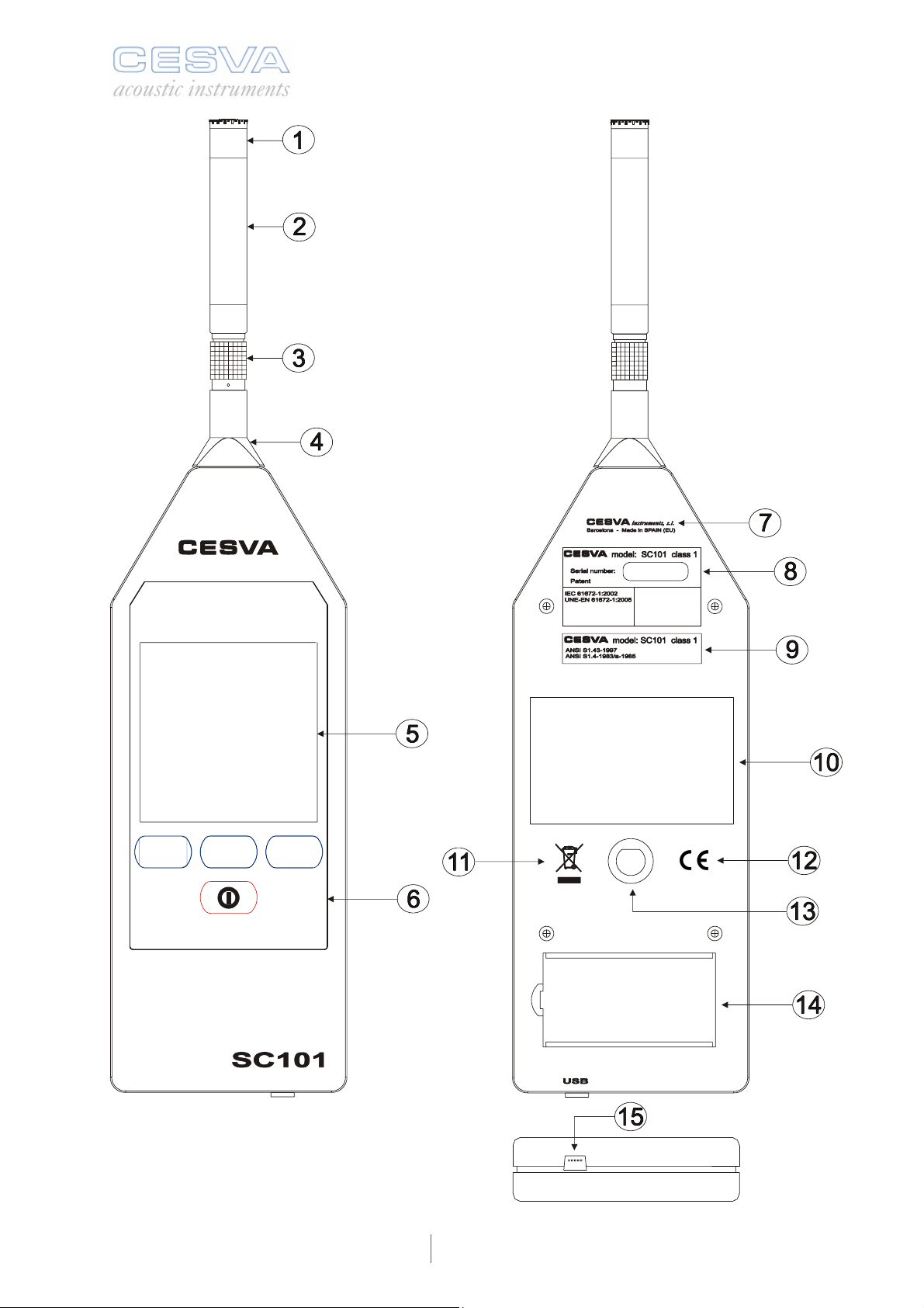
1.3 Description of the SC101
The following figure describes the most important parts of the SC101:
1. ½’’ condenser microphone. The SC101 can operate with microphone model C-130
(polarised to 200 V) + the PA-13 preamplifier or with microphone model C-250 (prepolarised) + the PA-14 preamplifier. Both these models are precision condenser
microphones. The SC101 is a class 1 sound level meter with both microphones.
Preamplifier. The SC101 includes the PA-13 removable preamplifier (for C-130) or
2.
the PA-14 (for C-250), which connects via the LEMO connector (3).
LEMO connector of the preamplifier. Male LEMO connector of the preamplifier.
3.
LEMO connector of the sound level meter. Female LEMO connector of the SC101
4.
sound level meter.
Screen. Graphic LCD screen.
5.
Membrane keypad. Extra-flat keypad designed to reduce the reflections reaching the
6.
microphone from the case of the sound level meter.
Manufacturer’s information.
7.
8. Name plate in accordance with IEC. This area contains details such as make,
model, class and serial number of the sound level meter, as well as all the
international regulations it fulfils as class 1 and its metrology marking.
Name plate in accordance with ANSI.
9.
Space reserved for the periodic inspection label. Space reserved for a label
10.
showing that the sound level meter complies with periodic inspection requirements
(Order ITC/2845/2007).
11. WEEE mark. Symbol indicating separate collection of electrical and electronic
devices.
CE mark. European conformity mark.
12.
Tripod support. Embedded tripod support, with 14” W standard thread. (TR-40 and
13.
TR050).
Battery cover. Cover for the battery compartment, only to be removed when
14.
changing the batteries.
USB connector. USB Mini-B connector for USB 1.1 full-speed bi-directional digital
15.
communication.
7
Page 10
8
Page 11

SC101
User’s Manual
1.4 Screen and use of the keypad
The SC101 has a main menu with icons that provide access to the various applications and
settings of the device.
The top left corner of the screen always shows the active application or setting:
Main menu
Sound level meter application
Vehicle application
Leisure and community application (area)
Leisure and community application (points)
Occupational hazard application
Machinery application: sound pressure
level
Machinery application: sound power level
Sensitivity setting
Contrast setting
Next to the above indications is a battery-shaped
symbol which shows the current charge level of the
batteries (see section 2.1.2).
Inside each application, the top right corner of the
screen shows information on the elapsed
measurement time and its current status:
• Running
• Stopped
• Or paused
The keypad of the SC101 has an on/off button
key buttons. The function of these buttons varies according to the indications at the bottom of
the screen, directly above each of them.
The following tables describe the meaning of the indications used for the buttons of the
SC101 in the various applications:
9
and three flexibly programmable soft-
Page 12
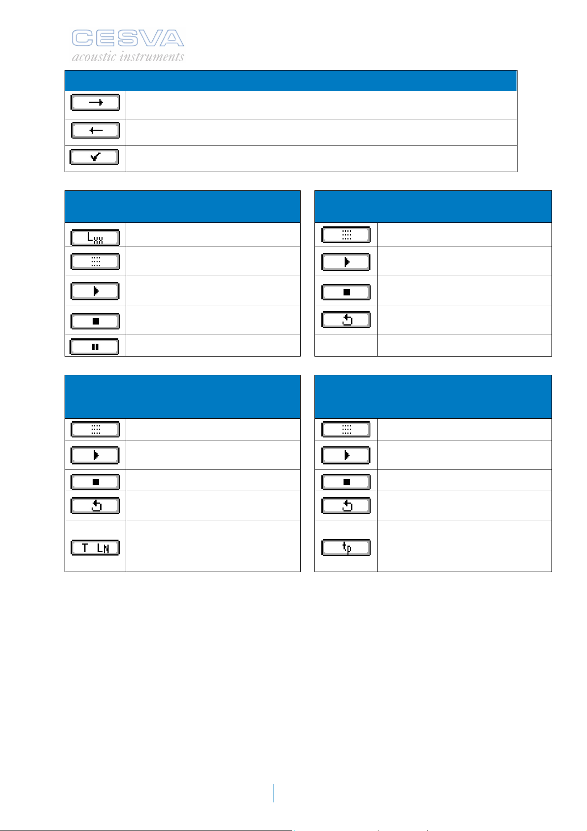
MAIN MENU BUTTONS
Button for moving to the right, next icon, within the menu
Button for moving to the left, previous icon, within the menu
Button for accessing the application or setting corresponding to the selected icon
SOUND LEVEL METER APPLICATION
BUTTONS
Button for changing the functions
viewed on the screen
Button for returning to the main menu
Button for starting or resuming the
measurement
Button for ending the measurement
Button for pausing the measurement
LEISURE AND COMMUNITY APPLICATION
BUTTONS (CORRECTION BY AREA AND BY
POINTS)
Button for returning to the main menu
Button for starting or resuming the
measurement
Button for ending the measurement
Button for cancelling the
measurement
VEHICLE APPLICATION BUTTONS
Button for returning to the main menu
Button for starting or resuming the
measurement
Button for ending the measurement
Button for cancelling the
measurement
OCCUPATIONAL HAZARD APPLICATION
BUTTONS
Button for returning to the main menu
Button for starting or resuming the
measurement
Button for ending the measurement
Button for cancelling the
measurement
Button for entering the measurement
time and indicating whether a
background noise measurement is
required
Button for entering the projection
time
10
Page 13
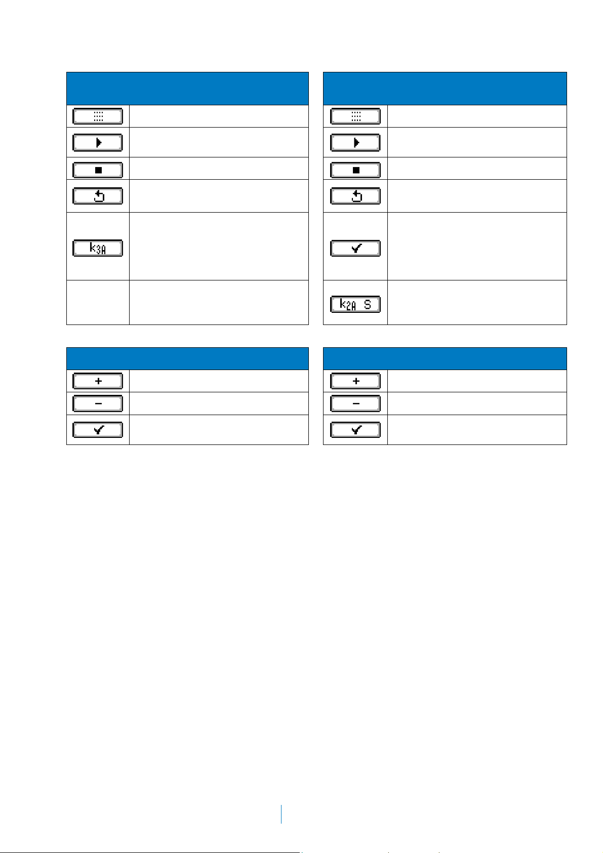
SC101
User’s Manual
MACHINERY SOUND PRESSURE APPLICATION
BUTTONS
Button for returning to the main menu
Button for starting or resuming the
measurement
Button for ending the measurement
Button for cancelling the
measurement
Button for entering the environmental
correction
SENSITIVITY SETTING BUTTONS
MACHINERY SOUND POWER APPLICATION
BUTTONS
CONTRAST SETTING BUTTONS
Button for returning to the main menu
Button for starting or resuming the
measurement
Button for ending the measurement
Button for cancelling the
measurement
Button for ending the sound pressure
measurements with the machine
switched on and starting the
background noise measurements
with the machine switched off
Button for entering the test acoustic
environment correction and the
measurement surface area
Button for increasing the sensitivity
Button for reducing the sensitivity
Button for confirming the sensitivity
setting
Button for increasing the contrast
Button for reducing the contrast
Button for confirming the contrast
setting
11
Page 14
2. OPERATING THE SC101
This chapter contains all the information required for setting, adjusting and performing
measurements using the SC101.
2.1 First steps
This section contains the steps to be performed before starting to use the SC101.
2.1.1 Equipment and documents
The first step is to check the equipment and documents supplied with the SC101:
Equipment included:
• SC101 sound level meter
• Protective case
• Windscreen
• Two 1.5 V alkaline batteries
Documents included:
• User’s Manual
• Warranty
If any of these elements are missing, please contact your official
distributor.
2.1.2 SC101 power supply
The first operation to be performed, before switching on the SC101, is to power it.
The SC101 sound level meter uses two AA (LR6) 1.5 V alkaline batteries, or else can be
powered via the USB port [15]. If both systems are used at the same time (batteries + USB
port), the SC101 chooses whichever one offers the highest voltage.
CESVA PB015 rechargeable batteries can also be used.
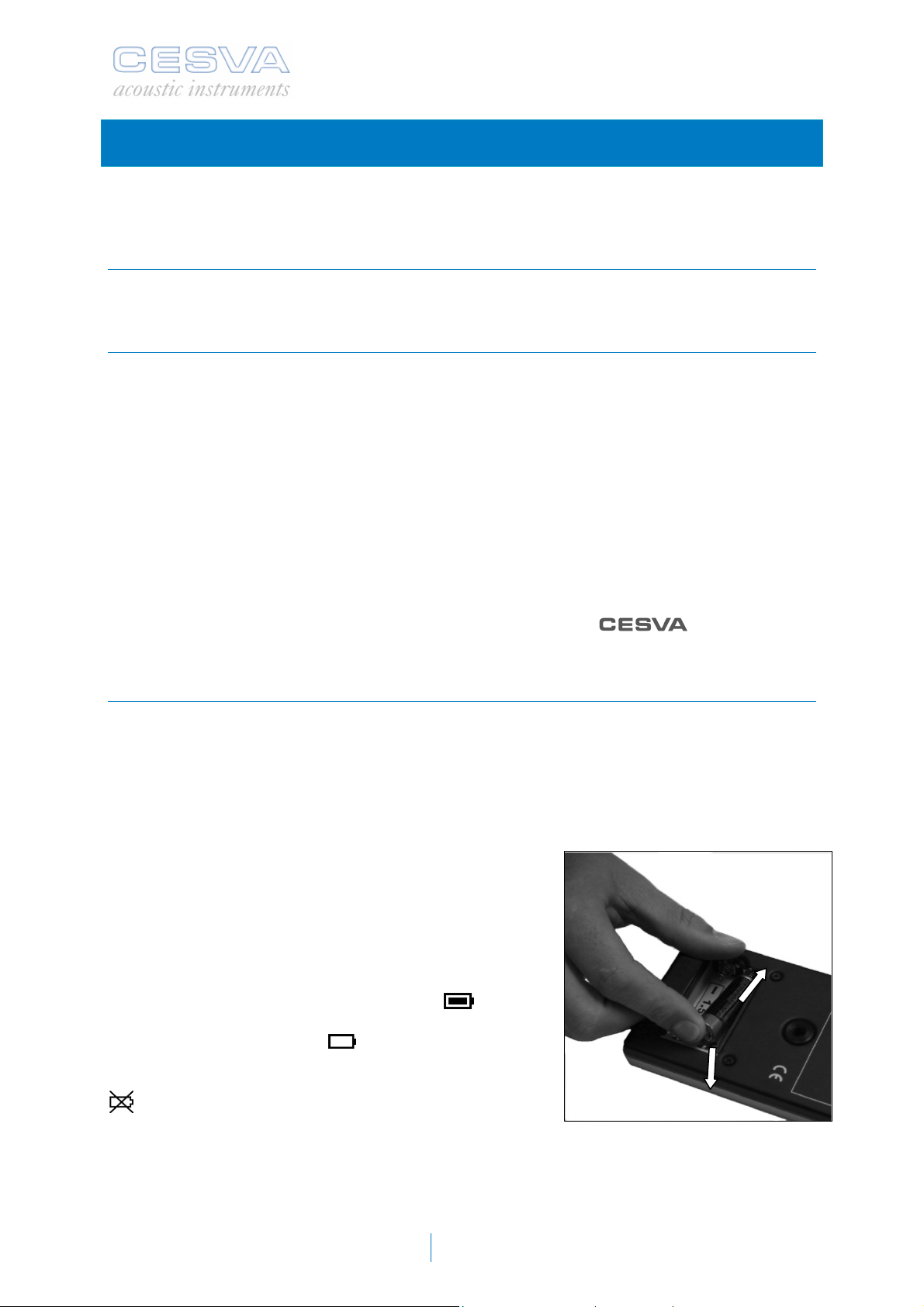
To install the batteries, remove the battery compartment
cover [ 14] located on the rear of the SC101. Place the
two batteries as shown in the battery compartment in the
drawing. To do this, press the negative pole of the
battery against the spring and push the battery in so that
the positive pole (raised) presses against the smooth
metal contact.
When the battery is fully charged, the symbol
appears on the screen. The symbol gradually empties as
the battery loses its charge:
of the battery is too low for the SC101 to continue
operating correctly, a crossed-out empty battery symbol
will appear at the centre of the screen for two
seconds, before switching off. The batteries must be
replaced.
1
. When the charge level
2
12
Page 15
SC101
User’s Manual
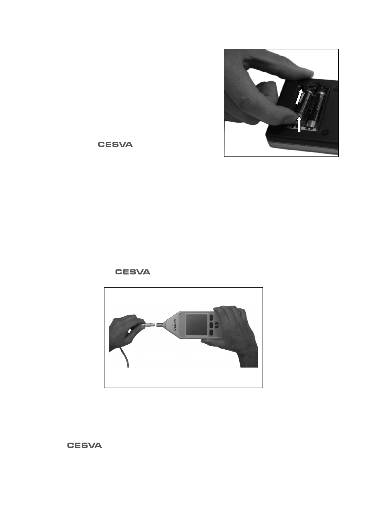
The device must be switched off before replacing the
batteries. To remove the batteries from the SC101, open
the battery compartment and press the battery against
the spring while pulling it outwards, holding the battery
by its positive pole as shown in the figure.
The SC101 can also be powered via the USB Mini-B
port. For this, use the CN1US cable to connect the USB
port of the SC101 [15] to a USB port on a PC. When
connected this way, the screen will show “USB” in place
of the battery symbol.
NOTE: to enable automatic switch-on via USB port,
contact an official
TIPS:
If the SC101 is likely to be unused for an extended period, remove the batteries from the
SC101 to avoid potential damage caused by the batteries leaking.
dealer.
1
1
1
2
2
2
1
2
It is advisable always to carry new spare batteries
.
2.1.3 Connecting and disconnecting the preamplifier, using the extension
cable and outdoor kit
The microphone of the SC101 is completely removable. This allows the microphone to be
separated from the sound level meter and the operator. By doing so, the SC101 can be
operated at a distance from the measurement point, avoiding potential interference. To
perform this operation,
metres) or CN030 (30 metres) must be used.
extension cable models CN003 (3 metres), CN010 (10
WARNING! : It is important to make sure the sound level meter is switched off before
attaching or detaching the microphone.
The preamplifier + microphone form an indivisible unit. The microphone is screwed into the
preamplifier. Do not unscrew the microphone from the preamplifier unless strictly necessary;
the microphone might be damaged during handling.
NOTE:
which will be sufficient grounds for voiding the warranty.
To separate the preamplifier from the sound level meter, pull on the preamplifier connector
[
3] as shown in the figure. Do not pull on the preamplifier [ 2].
accepts no responsibility for any operations by unauthorised personnel,
13
Page 16
To reconnect the preamplifier to the sound level meter, reinsert the male LEMO connector of
the preamplifier [
3] into the female LEMO connector of the sound level meter [ 4] by hand,
until they click together. The red dot on the preamplifier connector must be aligned with the
red dot on the sound level meter connector.
WARNING! : Do not attempt to insert or remove the preamplifier by screwing the connector
[
3] as this will damage the sound level meter.
NOTE: The cables do not interfere with the measurement frequency band. It is not necessary
to recalibrate the device when using the extension cables.
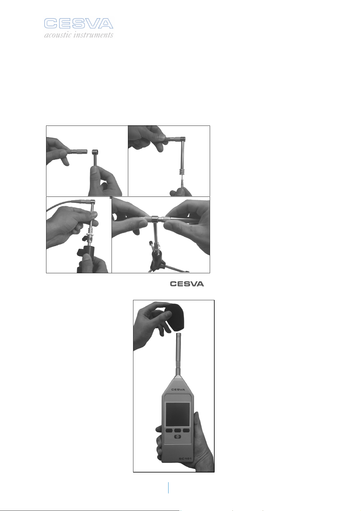
With an extension cable, the TR001 adapter can be used to
connect the preamplifier +
microphone to the TR-40 or TR-50
tripod. To do so, follow the steps
below:
1) Insert the female LEMO
1 2
connector of the extension
cable through the TR-001
adapter.
2) Fasten it with the screwdriver.
3) Place the adapter on the
4) Connect the preamplifier.
3 4
To avoid the effects of wind noise, the
attached to the microphone, as shown in the following figure.
windscreen, model PVM-05 can be
tripod.
14
Page 17
SC101
User’s Manual
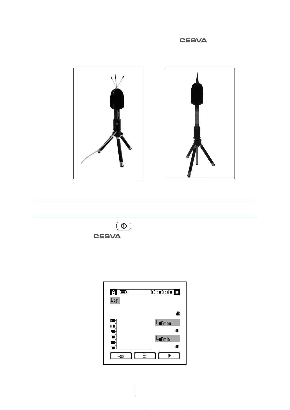
The measurement equipment can be completed with the outdoor kit, model
TK1000 or TK200, recommended for protecting the preamplifier + microphone unit from
adverse weather phenomena such as moderate rain and wind, birds, insects, humidity, etc.
The outdoor kits include a windscreen, rain protection, bird protection and a dehumidifier.
TK1000 TK200
2.2 Starting a measurement
2.2.1 Starting up the SC101
To switch on the SC101 press the button.
The screen shows the logo next to the model number: SC101. After a few
seconds, it displays the screen of the last application used. If the SC101 is being used for the
first time or no applications were active when it was last switched off, the main menu
appears.
is not ready to begin measuring. No measurements can be started until this symbol
disappears (approximately 10 seconds). It is possible, however, during this interval to access
or move around the main menu.
At the same time, an hourglass symbol appears, to show that the sound level meter
If the SC101 does not switch on, check its power supply.
15
Page 18
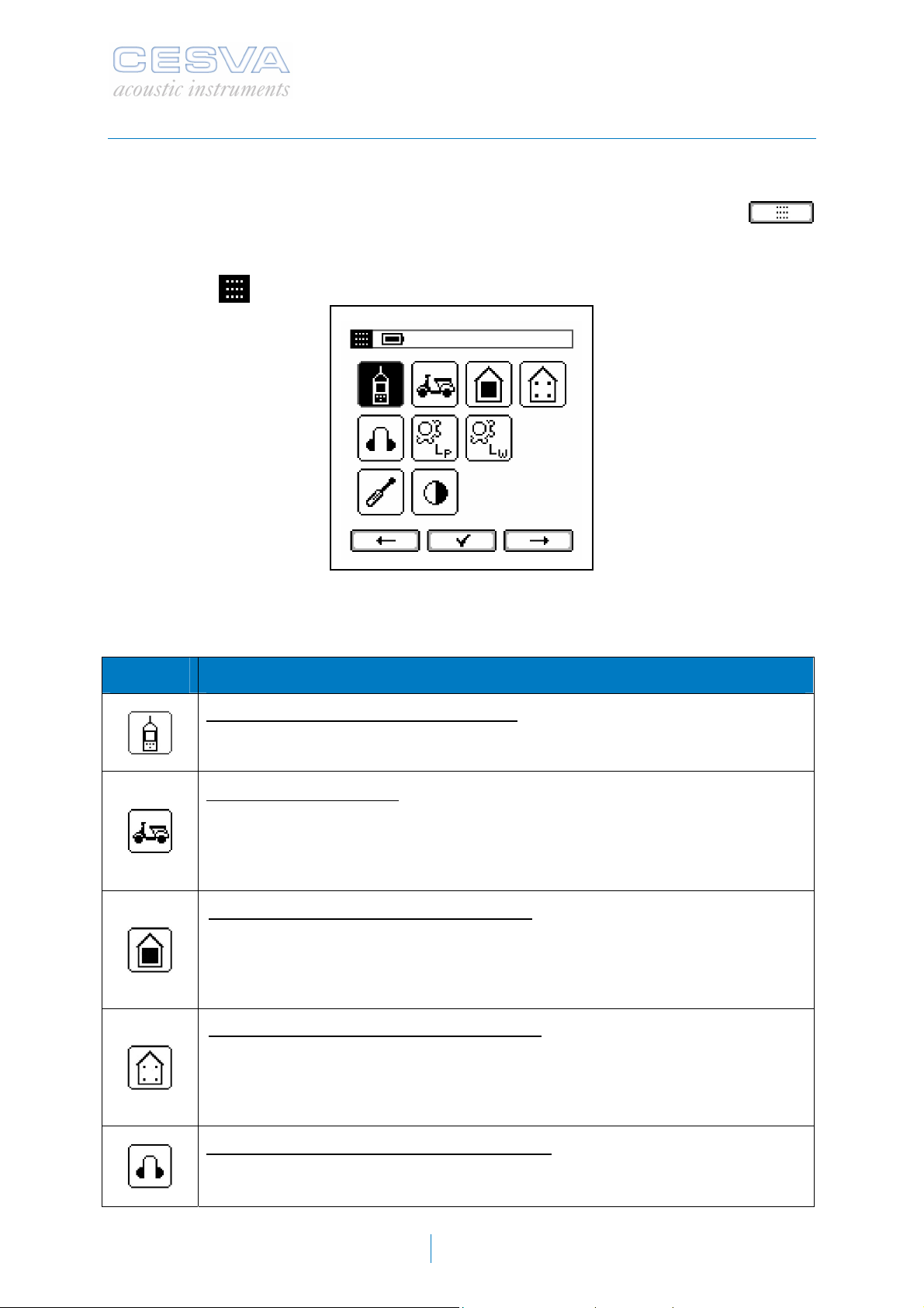
2.2.2 Main menu of the SC101: Selecting applications and settings
Once the sound level meter is switched on, it displays the main menu or the screen of the
last application used.
If the SC101 does not display the main menu, it can be accessed by pressing the
button.
When the SC101 is in the main menu, the following indication appears in the top left corner
of the screen (
).
The main menu shows various icons corresponding to applications or settings of the sound
level meter. These icons are as follows:
ICON APPLICATION or SETTING
SOUND LEVEL METER APPLICATION: Generic application for determining
sound levels. It can be adjusted to comply with a large number of regulations. It
measures all the functions simultaneously.
VEHICLE APPLICATION: Application for determining the sound level (L
generated by the exhaust system of motor vehicles: cars, public transport
vehicles, goods vehicles, motorcycles, mopeds, three-wheeled vehicles, allterrain bikes and quads. Test with vehicle stopped in accordance with
Directives 70/157/EEC, 78/1015/EEC and 97/24/EC Chap. 9.
LEISURE AND COMMUNITY (AREA): Determining the emission and
immission sound levels of businesses and residents in accordance with
various municipal bylaws in which the specified procedure consists of
averaging the background noise and the activity noise, in order to
subsequently apply the background noise correction.
LEISURE AND COMMUNITY (POINTS):
immission sound levels of businesses and residents in accordance with the
various municipal bylaws in which the specified procedure consists of
measuring the background noise and the activity noise in each of the points to
be assessed, and corrected with its corresponding background noise.
Determining the emission and
AFmax
)
OCCUPATIONAL HAZARDS APPLICATION: Application for determining the
sound levels (
with ISO 9612, determination based on tasks, jobs or working days.
L
EX,8h
, L
) of noise exposure in the workplace. In accordance
Cpeak
16
Page 19
SC101
User’s Manual
MACHINERY – SOUND PRESSURE APPLICATION: Application for
determining the noise levels (
in the workplace. In accordance with Directives 2005/88/EC and 2006/42/EC
and ISO 11202.
MACHINERY – SOUND POWER APPLICATION: Application for determining
the sound power level (
2005/88/EC and 2006/42/EC and ISO 3746.
SENSITIVITY SETTING: SC101 sensitivity setting.
CONTRAST SETTING: Screen contrast setting.
L
, L
pA
L
) of noise sources. In accordance with Directives
WA
) emitted by machines and equipment
Cpeak
Select the required application or setting using the
and buttons and press
to confirm.
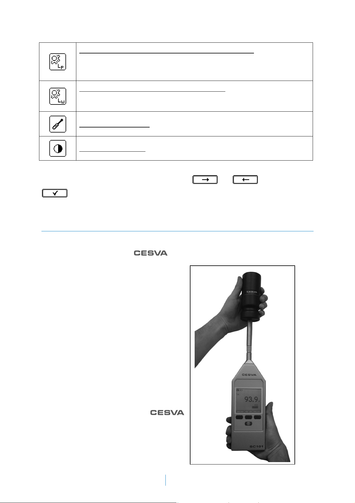
2.2.3 Checking the SC101
It is advisable to check the SC101 before and after taking a measurement.
To check the SC101, use the
steps below:
1) Place the SC101 in the calibrator,
inserting the microphone in the
calibration cavity. Make sure it enters the
cavity fully in a position parallel to the
calibrator axis (see figure). There may be
a certain amount of resistance, since the
calibrator fits onto the sound level meter
tightly. Insert the SC101 gently to avoid
damaging the microphone.
Start up the calibrator and check the
2)
battery status. The LED indicator must
remain lit throughout the entire calibration
process (see the calibrator manual). The
calibrator generates a 94 dB tone at 1
kHz.
sound calibrator, model CB006, and follow the
Apply the free-field pressure corrections
3)
of the microphone at 1 kHz. The free-field
pressure correction of the
C-130 / C-250 microphone at 1 kHz is -
0.1 dB. In other words, the SC101 must
be set to 93.9 dB.
17
Page 20
4) Go to the main menu of the SC101 and use the arrow keys to select the sensitivity
setting icon
5) Check that the value displayed at the centre of the screen (large digits) matches the
value of 94.0 dB, corrected by the relevant corrections (93.9 dB).
If the reading value is more than ± 0.3 dB off the calculated value, the sensitivity of the sound
level meter needs to be adjusted. This adjustment system has a tracing system to keep a
control of the times this adjustment has been made (see section 2.11). If this is not the case,
the sound level meter is measuring correctly and the sensitivity of the SC101 does not need
to be readjusted.
To return to the main menu, press the button.
IMPORTANT NOTE: The sensitivity of the sound level meter should only be adjusted by
authorised, technically competent personnel. Readjusting the sensitivity can lead to a loss of
device calibration traceability.
. Access it using the button.
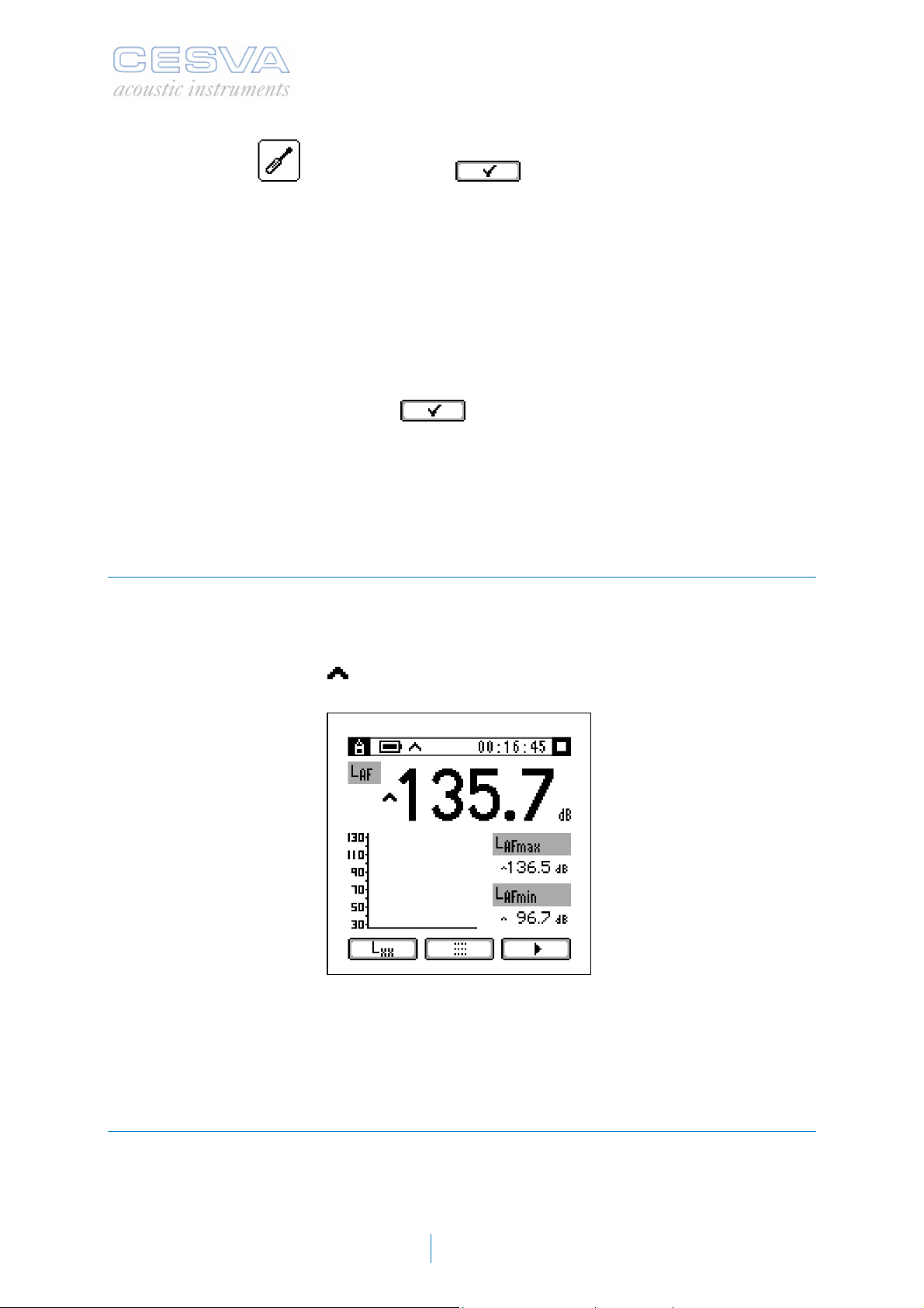
2.3 Saturation
The SC101 has a saturation indicator for each function. If saturation occurs during the
measurement, the ^ sign will be added in front of the value of the function affected.
Whenever a function registers saturation, its measurement is incorrect.
When saturation occurs, the indication appears in the top left corner of the screen.
If the saturation indicator appears during the measurement, the SC101 will not allow the
measured values to be validated and it will not be possible to move on to the next
measurement phase (except in the conventional sound level meter application, which does
not have different measurement phases).
2.4 Measuring with the sound level meter application
This application aims to make the noise measurement process easier for the user. It provides
a graphic and numerical follow-up of the temporal development of the sound event. For the
user’s convenience, three functions are displayed simultaneously, and the functions
displayed can be changed during the measurement process as required.
18
Page 21
SC101
User’s Manual
The sound level meter application is ideal for taking measurements of overall sound pressure
levels, with both instant and averaged values based on integration (equivalent level). The
SC101 measures all the functions at once.
With this application, measurements can be taken to comply with a broad range of
regulations.
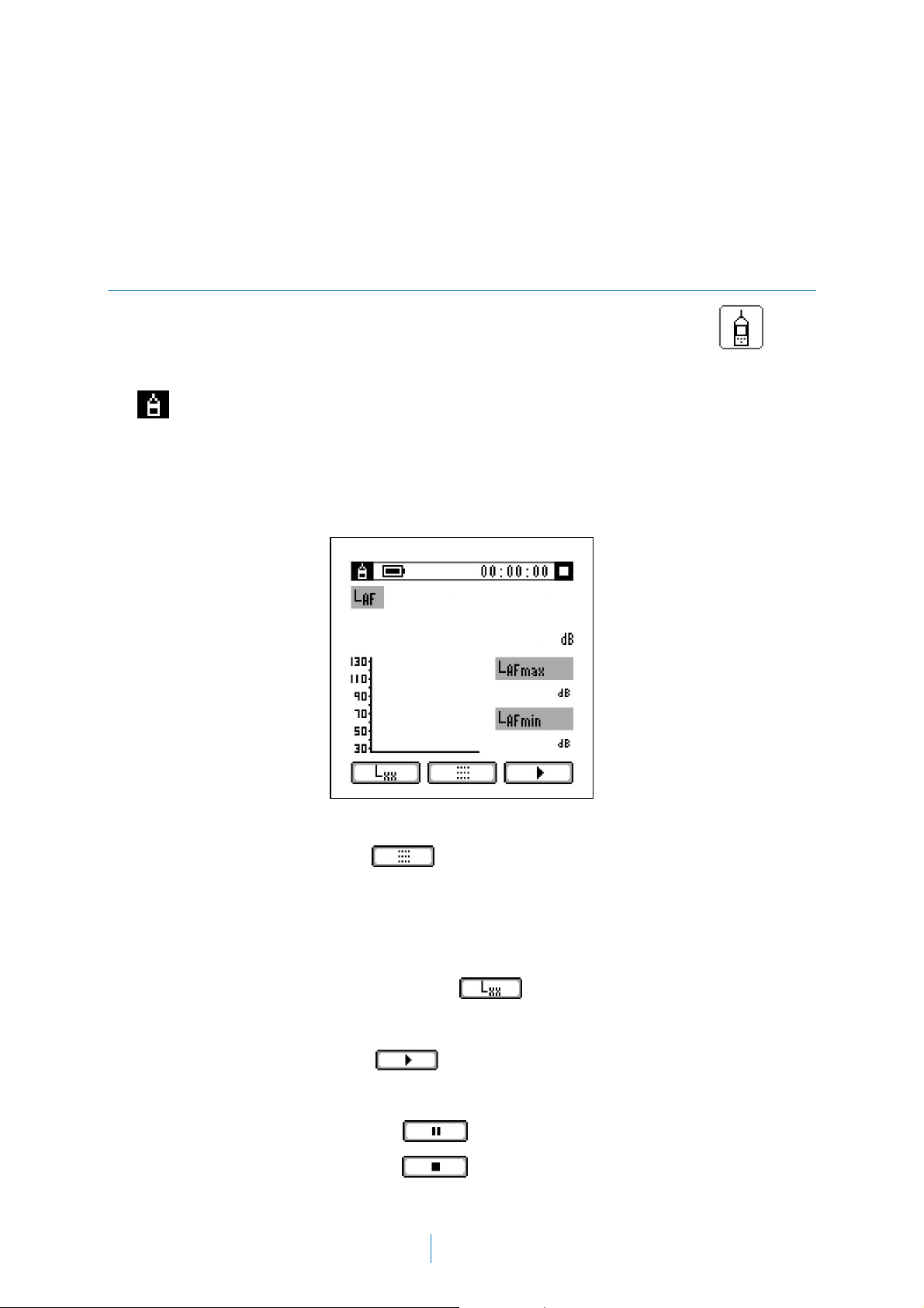
2.4.1 Starting a measurement
From the main menu, the sound level meter application can be accessed via the icon.
The following appears at the top of the screen:
o
o Power indicator (see
o Clock (00:00:00): Counts the measurement time elapsed.
o Measurement status indicator (Stop, Play, Pause).
To return to the main menu, press
: Identifies the application.
2.1.2).
.
The start screen of this application shows three functions in numerical format and the main
function in graphic format.
This screen enables the user to:
o Change the functions displayed, using the
o Perform a measurement.
To start a measurement, press the
Once the measurement has started, it is possible to:
o Pause the measurement using the
o End the measurement by pressing
button.
button.
19
button
Page 22

To resume a paused measurement, press . The clock on the screen stops while the
measurement is paused.
2.5 Measuring with the vehicle application
This application aims to make it easier for the user to take measurements of the sound level
generated by motor vehicle exhaust systems.
The application performs, step-by-step, the measurement process to be followed when
assessing the noise produced by motor vehicles, in accordance with Directives 70/157/EEC,
78/1015/EEC and 97/24/EC Chap. 9. (see APPENDIX B: Vehicle noise).
This is the ideal solution for roadworthiness testing centres. It also checks the values
obtained during the measurement in real time. This feature allows the user to make decisions
on the spot.
2.5.1 Starting a measurement
From the main menu, the vehicle application can be accessed via the icon.
The following appears at the top of the screen:
o
o Power indicator (see
o Clock (00:00:00): Counts the measurement time elapsed.
o Measurement status indicator (Stop, Play, Pause).
To return to the main menu, press
: Identifies the application.
2.1.2).
.
20
Page 23
SC101
User’s Manual
2.5.2 Background noise measurement
Before starting to assess the noise generated by the motor vehicle exhaust system, the
background noise without the vehicle or with its engine turned off must be measured.
To begin the measurement process, press
levels which can be seen at the top of the screen.
To halt the measurement, press
and the value appears automatically in the LN field.
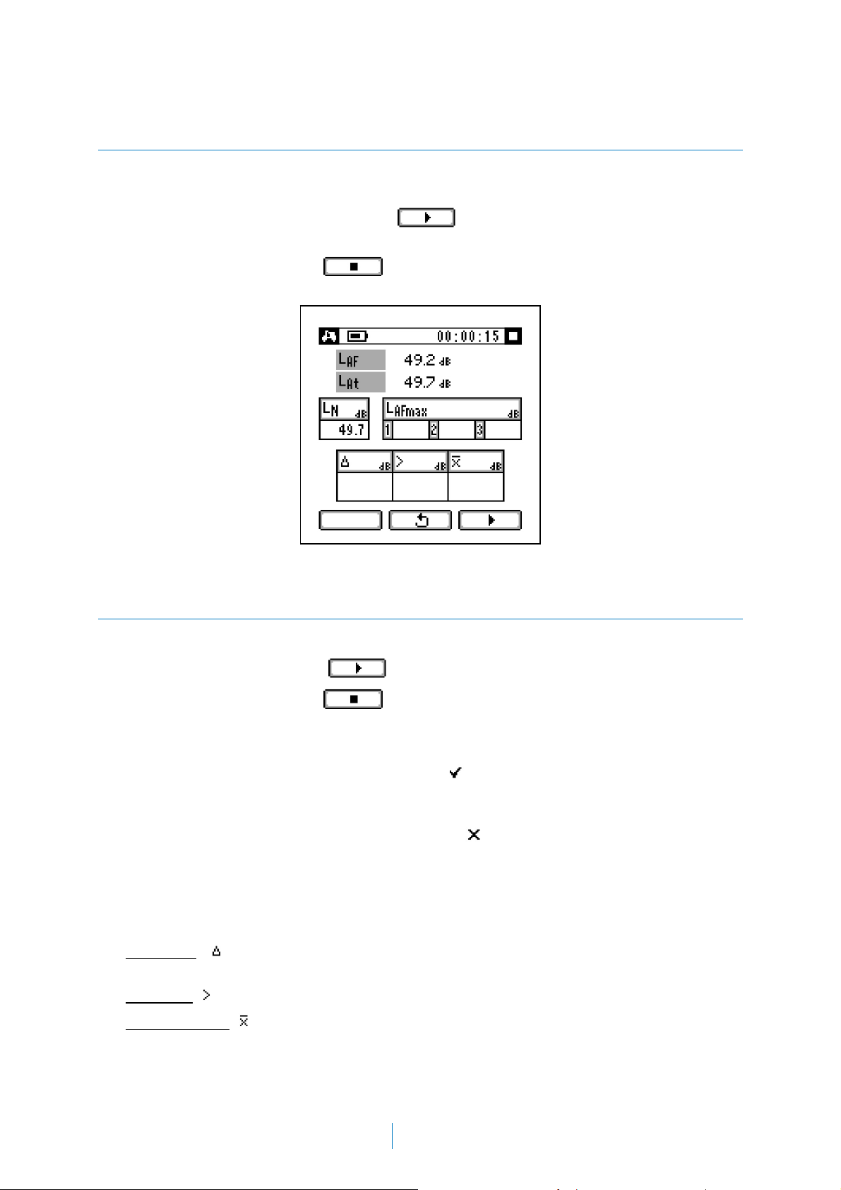
2.5.3 L
AFmax
measurement
. The SC101 will measure the LAF and L
At
Once the background noise has been obtained, the SC101 is ready to measure L
To start the measurement, press
To halt the measurement, press
The device automatically checks whether the value of L
background noise L
o If L
LN + 10, L
AFmax
:
N
will be marked with a at the top of the screen to show that the
AFmax
. The sound level meter measures LAF and L
.
is at least 10 dB higher than the
AFmax
value is correct, and it appears rounded to the nearest integer in the relevant L
AFmax
AFmax
(the first measurement appears in the first box, and so on).
o If L
< LN + 10, L
AFmax
will be marked with an at the top of the screen to show that
AFmax
the value is not correct and will not be taken into account. The measurement must be
repeated.
Whenever the three L
o Difference
( ): the maximum value minus the minimum value of the three L
boxes are filled, the following parameters appear automatically:
AFmax
measurements.
o Maximum
( ): the maximum value of the three L
o Linear average
( ) of the three values rounded to the nearest integer.
measurements.
AFmax
.
AFmax
box
AFmax
.
21
Page 24
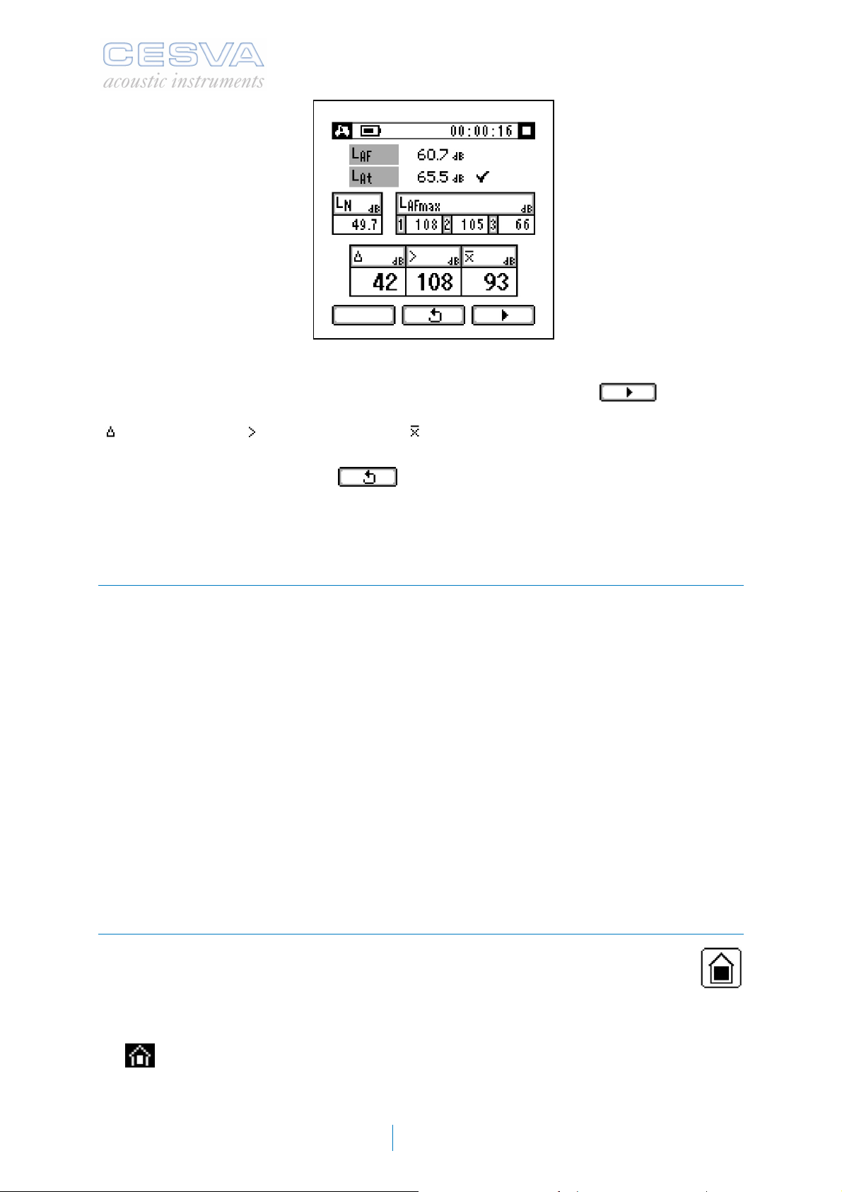
Once the three measurements of L
possibility of taking more L
measurements. To continue, press . The latest
AFmax
have been taken, the SC101 offers the user the
AFmax
measurement will replace the oldest one stored and the SC101 will calculate the difference
(
), maximum level ( ) and linear average ( ) fields again using the three values of L
AFmax
shown on the screen.
To cancel a measurement, press
. The SC101 will return to the start screen of the
application, ready for a new measurement, and all previously measured data will be lost.
2.6 Measuring with the leisure and community application (correction by
area)
The leisure and community application aims to help the user with the task of inspecting noise
pollution levels produced by businesses (pubs, bars, shops, etc.) and residents (electrical
appliances, TV, people, etc.). The results of these measurements are later compared with
the emission and immission limit values stipulated in the applicable by laws.
The application performs, step-by-step, the measurement process to be followed for
inspecting noise levels both indoors and outdoors, in accordance with applicable municipal
bylaws in which the specified procedure consists of averaging the background noise and the
activity noise, in order to subsequently apply the background noise correction (see
APPENDIX C: Leisure and community). It is the perfect solution for inspections by police and
city council technicians. It also checks the values obtained during the measurement in real
time. This feature allows the user to make decisions on the spot.
In the process for inspecting emission and immission levels stipulated in the bylaws, several
measurements must be taken, as well as taking other factors into account. With this
application, however, the user only needs to focus on the results obtained, since the device
takes care of checking all the other points.
2.6.1 Starting a measurement
From the main menu, the leisure and community application can be accessed via the
icon.
The following appears at the top of the screen:
o
o Power indicator (see
o Clock (00:00:00): Counter:
: Identifies the application.
2.1.2).
22
Page 25

SC101
User’s Manual
o If the SC101 is working: shows the elapsed measurement time.
o If the SC101 is stopped: shows the time elapsed between the end of one
measurement and the start of the next one.
o Measurement status indicator (Stop, Play, Pause).
To return to the main menu, press
.
Before starting a measurement:
1. Enter the measurement time (this time will be used
for all the measurements made).
2. Specify whether or not background noise
correction will be applied.
To enter the measurement time T (mm:ss):
o Press
o Select the numerical value using
o Confirm with
and
Repeat the process to change the seconds.
The measurement time T (mm:ss) can have the following values:
o 0 to 59 for mm (minutes)
o 0 to 59 for ss (seconds)
Next, specify whether or not a background noise measurement will be taken. Proceed as
follows:
o Use the
o
o
o Confirm the option with
and buttons to select the relevant option:
(background noise correction is not applied)
(background noise correction is applied)
2.6.2 Background noise measurement (optional)
If the background noise correction is to be performed, follow the steps described in this
section. Otherwise, skip to the next section (
To start the measurement, press
Once the time T has elapsed, the measured value of L
entered in the L
box.
N
This application enables as many background noise measurements as necessary to be
made.
2.6.3)
.
appears automatically and is
AT
23
Page 26

To continue with the measurements, press
.
The values will be taken into account when calculating
the final results.
Once the measurements have been made, they must be
validated by pressing
To cancel a measurement, press
.
. The SC101
will return to the start screen of the application, ready for
a new measurement, and all previously measured data
will be lost.
2.6.3 L
and L’At measurement
At
To start the measurement, press .
As with the background noise measurement, the measurement will stop automatically once
the time T has elapsed, and the measured value for the L
function will appear. The
AT
following data will appear at the same time:
number of measurements taken to calculate LAt.
o N:
Difference between the maximum and minimum value of the measured LAT values.
o :
o L
o L:
: Average energy of the measured LAt values.
At
Difference between LAt and LN.
o If L < 3, L will be marked with the
symbol to show that it is not correct
and that the last measurement needs to be repeated, since it cannot be taken
as valid.
o L’
: Value of LAt corrected for background noise.
At
o If you chose not to measure the background noise or L 10: L
o If 3 L >10, the SC101 applies the background noise correction.
The SC101 offers the possibility of performing more L
To continue with the measurements, press
measurements.
AT
. The values will be taken into account
when calculating the final results.
If
is pressed before the time T has elapsed, a
new measurement is started, without taking into account
the result of the previous L
for calculating the end
AT
results.
= L’At
At
To cancel a measurement, press . The SC101
will return to the start screen of the application, ready for a
new measurement and all previously measured data will
be lost.
24
Page 27

SC101
User’s Manual
2.7 Measuring with the leisure and community application (correction by
points)
The leisure and community application aims to help the user with the task of inspecting noise
pollution levels produced by businesses (pubs, bars, shops, etc.) and residents (electrical
appliances, TV, people, etc.). The results of these measurements are later compared with
the emission and immission limit values stipulated in the applicable bylaws.
The application performs, step-by-step, the measurement process to be followed for
inspecting noise levels both indoors and outdoors, in accordance with applicable municipal
bylaws in which the specified procedure consists of measuring the background noise and the
activity noise in each of the points to be assessed, and corrected with its corresponding
background noise (see APPENDIX C: Leisure and community). It is the perfect solution for
inspections by police and city council technicians. It also checks the values obtained during
the measurement in real time. This feature allows the user to make decisions on the spot.
In the process for inspecting emission and immission levels stipulated in the bylaws, several
measurements must be taken, as well as taking other factors into account. With this
application, however, the user only needs to focus on the results obtained, since the device
takes care of checking all the other points.
2.7.1 Starting a measurement
From the main menu, the leisure and community application can be accessed via the
icon.
The following appears at the top of the screen:
o
o Power indicator (see
o Clock (00:00:00): Counter:
o Measurement status indicator (Stop, Play, Pause).
: Identifies the application.
2.1.2).
o If the SC101 is working: shows the elapsed measurement time.
o If the SC101 is stopped: shows the time elapsed between the end of one
measurement and the start of the next one.
25
Page 28

To return to the main menu, press .
Before starting a measurement:
1. Enter the measurement time (this time will be used for all the measurements made).
2. Specify whether or not background noise correction will be applied.
To enter the measurement time T (mm:ss):
o Press
o Select the numerical value using
o Confirm with
and
Repeat the process to change the seconds.
The measurement time T (mm:ss) can have the following values:
o 0 to 59 for mm (minutes)
o 0 to 59 for ss (seconds)
Next, specify whether or not a background noise measurement will be taken. Proceed as
follows:
o Use the
o
o
o Confirm the option with
and buttons to select the relevant option:
(background noise correction is not applied)
(background noise correction is applied)
2.7.2 Measurement without applying background noise correction
If the option not to apply background noise correction has been chosen, follow the steps
shown below.
Click on
and the values of the L
appear:
: Maximum L
o
o L’
: as background noise correction is not
AT
applied, this value will always be the same as L
: Number of measurements carried out to
o N
calulate L’
Difference between the maximum and minimum
o :
values of the L’
: Maximum L’AT value of all those measured.
o
o L’
: average of all the L’
At
. Once the T, interval has passed the measurement will stop automatically,
and L
AT
value of all those measured.
AFmax
.
At
measured.
AT
measured.
AT
functions will appear. The following data will also
AFmax
.
AT
26
Page 29

SC101
User’s Manual
With this application as many measurements of the activity as required can be taken.
To continue taking measurements click on
. These values will be taken into account
in the above results.
To cancel a measurement click on
.
To restart the process click on ; the SC101 will return to the starting screen of the
application, ready to start a new measurement, and data of any measurements taken so far
will be lost. To return to the main menu click on
.
2.7.3 Measuring with background noise correction
If the option to apply background noise correction has been chosen, follow the steps shown
below.
Click on
and the values of the L
appear. At the same time the background noise box (L
. Once the T, interval has passed the measurement will stop automatically,
and L
AT
functions pertaining to the background noise will
AFmax
) will be filled in with the value of LAT.
N
The sound level meter offers the option of restarting the measurement process
moving on to measure the noise level of the activity
. By clicking on once
the T interval has passed, the following data will appear:
o L:
Difference between LAT and LN.
o If L < 3 ; L will be marked with the
symbol indicating that it is incorrect
and the last measurement must be repeated as it cannot be taken as valid.
o L’
: Value of L
AT
o If L 10 ; L
corrected for background noise.
AT
= L’AT
AT
o If 3 L <10 ; the SC101 will apply the
background noise correction.
or
: Number of measurements carried out for the
o N
calculation of L’
Difference between the maximum and minimum
o :
values of the L’
: Maximum value of L’AT of all those measured.
o
o L’
: average of all the L’
At
.
At
measured.
AT
measured.
AT
27
Page 30

This application allows an unlimited number of measurements to be taken.
To continue taking measurements click on
in the above results.
To cancel a measurement click on
To restart the process click on , the SC101 will return to the starting screen of the
application, ready to start a new measurement, and data of any measurements taken so far
will be lost. To return to the main menu click on
.
. These values will be taken into account
.
2.8 Measuring with the occupational hazard application
The occupational hazard application is designed to help the user assess the levels perceived
by a worker during his/her working day. It allows the assessment to be made according to
working days, jobs and tasks. The data obtained can then be used to assess the PPE used
by workers according to the HML and SNR methods.
The application performs, step-by-step, the measurement process to be applied when
assessing hazards associated with the exposure of workers to noise, in accordance with the
Technical Guide for the assessment and prevention of hazards associated with exposure of
workers to noise, (see APPENDIX D: Occupational hazards). It is the perfect solution for
companies in terms of occupational hazard prevention services, both internally and
externally. It also checks the values obtained during the measurement in real time. This
feature allows the user to make decisions on the spot.
In the process for assessing occupational hazards, several measurements must be taken, in
addition to checking other factors. With this application, however, the user only needs to
focus on the results obtained, since the device takes care of checking all the other points.
2.8.1 Starting a measurement
From the main menu, the occupational hazard application can be accessed via the
icon.
The following appears at the top of the screen:
o
o Power indicator (see
o Clock (00:00:00): Counts the measurement time
o Measurement status indicator (Stop, Play, Pause).
To return to the main menu, press
: Identifies the application.
2.1.2).
elapsed.
.
To start the measurement, press
LAt, LCt and L
Cpeak
.
. The SC101 measures and displays the functions
28
Page 31

SC101
User’s Manual
To end a measurement, press . The SC101 performs the calculations automatically
and presents the results of the following parameters, per screen:
: average energy of the measured LAt values
o
o
: average energy of the measured LCt values
: maximum L
o
: number of measurements taken
o
: difference between the maximum and minimum value of the measured LAT values
o
o L
: projected equivalent daily exposure level, with A frequency weighting.
EX,8hp
value of all the measured values
Cpeak
The application allows all the required measurements to be performed.
To take another measurement, press
.
These measurements will be taken into account when calculating the parameters above.
To cancel a measurement, press . The SC101 will return to the start screen of the
application, ready for a new measurement, and all previously measured data will be lost.
To change the projection time, the measurement process must be stopped
(see 2.8.2).
2.8.2 Projection time
To assess noise exposure for measurement times shorter than the exposure times, the
projected parameters must be calculated.
This application can be used to obtain the projected daily sound exposure level L
determines the sound exposure that would be obtained if the measurement time was equal
to the projection time. For this reason, only the projection time
(tp) corresponding to the
expected time of exposure to noise should be entered.
By default, the SC101 assigns 8 hours to the projection time, but this value can be edited.
To modify the value of tp:
o Make sure the measurement process is halted
o Press the
button.
.
EX,8hp
, which
29
Page 32

o Select the numerical value using and
o Confirm with
Repeat the process to change the minutes.
The projection time tp (hh:mm) can have the following
values:
o 0 to 24 for hh (hours)
o 0 to 59 for mm (minutes)
2.9 Measuring with the machinery application: sound pressure level
The machinery application (sound pressure level) aims to help the user with the task of
performing measurements to assess the sound pressure level generated by machines and
equipment in the workplace.
In this application, the sound level meter guides the user, in an intuitive, sequential manner,
through the steps of the measurement process described in Directives 2005/88/EC and
2006/42/EC and the ISO 11202 standard (see APPENDIX E: Machinery; sound pressure
level). It also checks the values obtained during the measurement in real time, allowing the
user to make decisions on the spot.
In the process for assessing the sound pressure level of machines, various types of
measurements need to be taken, in addition to checking other factors. With this application
however, the device stores the values in order to perform all the checks, leaving the user free
to focus on the results obtained.
2.9.1 Starting a measurement
From the main menu, the machinery application: sound pressure level can be accessed via
the
The following appears at the top of the screen:
o
o Power indicator (see
o Clock (00:00:00): Counts the elapsed measurement
o Measurement status indicator (Stop, Play, Pause).
icon.
: Identifies the application.
2.1.2).
time.
To return to the main menu, press
.
30
Page 33

SC101
User’s Manual
2.9.2 Background noise measurement
Before starting to determine the noise levels (LpA, L
) emitted by machines and
Cpeak
equipment in the workplace, the background noise must be measured without any machines
or equipment, or with them switched off.
To begin the measurement process, press
displays L
and L
At
Cpeak.
. This performs the measurement and
To end the measurement, press . The background noise value is displayed in the
L’’
box.
pA
2.9.3 Obtaining L
pA
and L
Cpeak
levels
Once the background noise has been measured, the SC101 is ready to obtain LpA and L
To perform a measurement, press
To halt the measurement, press
: LAt points measured and used to calculate L’pA.
o N
o L’
o L
: Average energy of all the measured LAt values.
pA
: Difference between values L’pA and L’’pA.
o If L < 3, L will be marked with the
. The sound level meter measures LAt and L
. The following values appear automatically:
symbol to show that it is not correct
and that the last measurement needs to be repeated, since it cannot be taken
as valid.
Cpeak
Cpeak
.
.
31
Page 34

o K
: Background noise correction.
1A
o If L 10, K
= 0.0
1A
o If 3 L >10, the SC101 calculates the background noise correction
o K
o L
o L
: Environmental correction (see 2.9.4)
3A
: L’pA level corrected by K1A and K3A. The value is rounded to the nearest integer.
pA
: Maximum L
Cpeak
level measured. The value is rounded to the nearest integer.
Cpeak
NOTE: If L < 3, the values of fields k
cannot be calculated.
, k3A, LpA and L
1A
will not be displayed, since they
Cpeak
An LAt will be measured for every evaluation point. To measure another point, simply repeat
the procedure above. These measurements will be taken into account when calculating the
final results.
To cancel a measurement, press
. The SC101 will return to the start screen of the
application, ready for a new measurement, and all previously measured data will be lost.
2.9.4 K
The SC101 automatically calculates the K
and K
1A
corrections
3A
background noise correction.
1A
However, it is up to the user to enter the environmental correction value K3A (for more
information, see APPENDIX E: Machinery; sound pressure level).
To enter the environmental correction K
o Press the K
button.
3A
o Select the value using the
:
3A
and
buttons
o Confirm the value by pressing the
button
As of this time, the SC101 will take the new K
into account for calculating the end noise level (
value
3A
L
emitted by machines and equipment in the workplace.
32
pA
)
Page 35

SC101
User’s Manual
2.10 Measuring with the machinery application: sound power level
The machinery application (sound power level) aims to help the user with the task of
performing measurements to assess the sound power level generated by noise emissions
(machines).
In this application, the sound level meter guides the user, in an intuitive, sequential manner,
through the steps of the measurement process described in Directives 2005/88/EC and
2006/42/EC and the ISO 3746 standard (see APPENDIX F: Machinery sound power level). It
is the ideal solution for machinery manufacturers.
It also checks the values obtained during the measurement in real time. This feature allows
the user to make decisions on the spot.
In the process for assessing the sound power level of machines, various types of
measurements need to be taken, in addition to checking other factors. With this application
however, the device stores the values in order to perform all the checks, leaving the user free
to focus on the results obtained.
2.10.1 Starting a measurement
From the main menu, the machinery application: sound power level can be accessed via the
icon.
The following appears at the top of the screen:
o
o Power indicator (see
: Identifies the application.
2.1.2).
o Clock (00:00:00): Counts the measurement time
elapsed.
o Measurement status indicator (Stop, Play, Pause).
To return to the main menu, press
.
33
Page 36

2.10.2 Measuring the sound pressure level at several points
The first step in this application consists of measuring the sound pressure level at several
points with the noise emission switched on.
To perform a measurement, press
To end the measurement, press
. The LAt value is measured.
.
The following values appear automatically:
: LAt points measured and used to calculate L’pA.
o N
o L’
o
: Average energy of all the measured LAt values.
pA
: Difference between the maximum and minimum
value of L’
pA
.
o If 2·N, L will be marked with the
symbol to show that it is not correct.
This application can perform as many measurements as required, with the noise emission
switched on.
To continue taking more measurements with the noise emission switched on, press
These values will be considered in the above results.
Once these measurements are complete, they must be confirmed.
To confirm them, press
.
.
To cancel a measurement, press
. The SC101 will return to the start screen of the
application, ready for a new measurement, and all previously measured data will be lost.
2.10.3 Background noise measurement
Background noise is measured with the noise emission switched off.
NOTE: Perform the same number of background noise measurements as performed to
calculate L’
To perform background noise measurements, press
measure L
.
At
To end the measurement, press
The following values appear automatically:
: LAt points measured and used to calculate L’’pA.
o N
o L’’
o L
: Average energy of all the measured LAt values.
pA
: Difference between values L’pA and L’’pA.
pA
.
. The sound level meter will
.
o If L < 3, L will be marked with the
symbol to show that it is not correct
and that the last measurement needs to be repeated, since it cannot be taken
as valid.
34
Page 37

SC101
User’s Manual
o K
: Background noise correction.
1A
o If L 10, K
= 0.0
1A
o If 3 L >10, the SC101 calculates the background noise correction
o K
o L
o S m
o L
: Environmental correction (see 2.10.4).
2A
: L’pA level corrected by K1A and K2A.
pfA
2
: Surface area being assessed (see 2.10.4).
: Sound power level, calculated using the L
WA
value obtained and the S entered. The
pfA
value is rounded to the nearest integer.
To cancel a measurement, press
. The SC101 will return to the start screen of the
application, ready for a new measurement, and all previously measured data will be lost.
2.10.4 K
The SC101 automatically calculates the K
However, it is up to the user to enter the environmental correction value K2A (for more
information, see APPENDIX F: Machinery sound power level) as well as the value in m
and K
1A
corrections Surface area S
2A
background noise correction.
1A
2
of
the surface area S being assessed.
To enter the environmental correction K
o Press the
button
o Select the value using the
:
2A
and
buttons
o Confirm the value by pressing the
button
Repeat the last two steps to enter the surface area S.
35
Page 38

As of this time, the SC101 will take into account the new K2A and S values to calculate the
L
definitive sound power level (
) generated by machines.
WA
2.11 Sensitivity setting
IMPORTANT NOTE: The sensitivity of the sound level meter should only be adjusted by
authorised, technically competent personnel. Readjusting the sensitivity can lead to a loss of
device calibration traceability.
1) Go to the main menu of the SC101 and use the arrow keys to select the sensitivity
setting icon;
. Access it using the button.
2) Check that the value displayed at the centre of the screen (large digits) matches the
value of 94.0 dB, corrected by the relevant corrections (93.9 dB).
If the difference between the reading and the calculated value is less than ± 0.3 dB,
the sound level meter is working correctly.
Otherwise, the sensitivity of the sound level meter needs to be adjusted.
The procedure for adjusting the sensitivity is described below:
1) The SC101 allows the level to be adjusted using the and buttons.
Remember that any changes made to the sensitivity setting will be recorded. The sensitivity
adjustment screen shows the variation in dB, with a
counter showing the number of times this sensitivity
setting has been changed.
NOTE: This feature enables the user to keep control
of the number of times the sensitivity setting
has been changed.
2) To confirm the setting and return to the main
menu, press the
button.
36
Page 39

SC101
User’s Manual
2.12 Contrast setting
1) Go to the main menu of the SC101 and use the arrow keys to select the contrast
setting icon;
button.
2) The screen shows the contrast level in numbers,
as well as a sample of the four colours the
device can display, to be used as reference
when selecting the contrast level.
3) To change the contrast setting, press the
and buttons.
4) To confirm the setting and return to the main
menu, press the
. Access it using the
button.
2.13 Switching off the SC101
To switch off the SC101, check that no measurements are in progress ( ) and press:
2.14 Tips and warnings
When attaching and detaching the microphone, use only the hands, no tools. Do not do
this while the SC101 is switched on.
The microphone should never be dismantled, since this can cause permanent damage.
Keep the microphone away from dust and sharp objects.
Avoid excess moisture and sudden temperature changes that can cause condensation on
the microphone.
Do not remove the protective grid of the microphone unless strictly necessary. Never
touch the diaphragm. If the diaphragm is very dirty, remove the dust carefully using a very
fine camelhair brush.
diaphragm
Any impact on the SC101 will be picked up by the microphone and may affect the
measurement value.
When the SC101 is exposed to vibrations, it is advisable to insulate it. This can normally
be achieved using pads of foam rubber or similar materials.
When the measurements are taken outdoors, the supplied windscreen must be placed on
the microphone, since the wind can produce a very loud noise.
37
Page 40

When holding the SC101 by hand to take measurements, keep arm outstretched. To
avoid interference, we recommend using the TR-40 or TR050 tripod and the CN003,
CN010 or CN030 microphone extension cable. Remember that the microphone can only
be detached with the SC101 switched off.
It is advisable to check the SC101 before and after each measurement. Use the
CB006 acoustic calibrator. See section 2.2.3.
Remove the batteries if you will not be using the SC101 for an extended period.
The
for a long time. If any malfunction cannot be corrected by changing the battery or checking
the manual, send the SC101 to an official
have it repaired by unauthorised personnel.
This device will only work with the accessories listed in the Accessories section. If any
different accessories are used and this causes a failure in the device, will
assume no responsibility for this fault and the warranty will be void.
SC101 sound level meter is designed to provide reliable measurements
after-sales centre. Never attempt to
2.15 Tips for taking measurements
To prevent the operator from influencing the measurements (shielding effect) it is advisable
to take acoustic measurements with the sound level meter away from the body (without
making it difficult to read). For increased reliability, we recommend using the tripod. The axis
of the microphone should be pointed towards the noise source.
For indoor measurements, it is advisable to keep the sound level meter away from reflecting
surfaces (walls, objects, floors, etc.) to avoid adding the reflected noise to the noise being
measured.
For outdoor sound measurements, the sound level meter microphone should be protected
with the windscreen, and it is advisable to check the weather conditions (temperature,
humidity, atmospheric pressure).
When performing long-term outdoor measurements, it is advisable to use the TK1000 or
TK200 outdoor kit to protect the equipment against environmental agents (wind, rain,
moisture).
When measuring sound fields with very low levels, remember the measurement range
specifications. If a measure a level below the specified lower measurement limit is to be
made, the noise characteristics of the actual device must be taken into account.
3. VIEWING DATA ON A PC
The SC101 sound level meter has a USB port for communicating with a PC, via the CN1US
cable (see 4.22).
This port allows real-time transmission of the data measured by the SC101 to a computer,
with a high transfer rate.
If this communication is to be performed, contact an official after-sales centre.
38
Page 41

SC101
A
User’s Manual
4. TECHNICAL SPECIFICATIONS
4.1 Measurement range
Functions LF, LS and L
Starting point for the linearity tests 94 dB
t
For C-130 + PA-13
Electrical measurement range (with nominal microphone
sensitivity) at 1kHz:
Upper limit
Upper limit for crest factor 3:
Lower limit
Linear measurement range at 31.5 Hz:
Upper limit
Lower limit
Linear measurement range at 4 kHz:
Upper limit
Lower limit
Linear measurement range at 8 kHz:
Upper limit
Lower limit
Linear measurement range at 12.5 kHz
:
Upper limit
Lower limit
Electrical noise (with nominal microphone sensitivity without
preamplifier):
Maximum
Typical
Total noise at 20 °C (electrical + thermal of the microphone):
Maximum
Typical
FREQUENCY
WEIGHTING
C
137.0
130.0
24.8
97.6
24.8
138.0
24.8
135.9
24.8
132.7
24.8
15.7
15.0
21.2
20.6
137.0
130.0
25.8
134.0
25.8
136.2
25.8
134.0
25.8
130.8
25.8
17.1
16.3
22.0
21.8
Note: the intrinsic noise is measured with equivalent levels, with integration time of more
than 30 seconds.
39
Page 42

A
For C-250 + PA-14
Electrical measurement range (with nominal microphone
sensitivity) at 1kHz:
Upper limit
Upper limit for crest factor 3
Lower limit
Linear measurement range at 31.5 Hz:
Upper limit
Lower limit
Linear measurement range at 4 kHz:
Upper limit
Lower limit
Linear measurement range at 8 kHz:
Upper limit
Lower limit
Linear measurement range at 12.5 kHz:
Upper limit
Lower limit
Electrical noise (with nominal microphone sensitivity without
preamplifier):
Maximum
Typical
Total noise at 20 °C (electrical + thermal of the microphone):
Maximum
Typical
FREQUENCY
137.0
130.0
23.7
97.6
23.7
138.0
23.7
135.9
23.7
132.7
23.7
15.7
15.1
18.9
18.4
WEIGHTING
C
137.0
130.0
26.9
134.0
26.9
136.2
26.9
134.0
26.9
130.8
26.9
16.7
16.4
20.8
20.2
Note: the intrinsic noise is measured with equivalent levels, with integration time of more
than 30 seconds.
L
function
peak
Linear measurement range with C-130 and C-250:
Upper limit
Lower limit
141.0 dB
55.0 dB
40
Page 43

SC101
User’s Manual
4.2 Detector - Functions LF and LS
The ADM0C130 adapter should be used for electrical calibration.
Maximum applicable electrical voltage with the ADM0C130
adapter
Function Pulse duration (ms) Maximum error (dB)
L
F
L
S
Maximum error for signals with peak factor ≤ 3:
Maximum error of the maximum response to sinusoidal signal pulses
200 ± 1.0
500 ± 1.0
26 V pp
± 0.5 dB
Maximum reading excess:
:
L
F
L
:
S
Maximum level linearity error (31.5 to 12,500 Hz): ± 0.7 dB
Maximum level differential linearity error (31.5 to 12,500 Hz): ± 0.2 dB
4.3 Peak detector – Lpeak function
Rising time:
4.4 Averager – Lt function
Linearity range: 110 dB
Pulse range: 65 dB
Response time for a constant input signal: 2 s
4.5 Clock features
Screen refreshing time
1.1 dB
1.6 dB
< 75 µs
Screen refreshing time: 1 s
When starting a measurement, the value of the time-dependent functions will take a time T
to appear on the screen. This value is updated every second, although no changes will be
appreciated until the time T has elapsed.
41
Page 44

4.6 Frequency weighting
Available frequency weightings
Function
L
peak
L
F
L
S
L
t
The following table shows the A and C frequency weightings as well as the tolerance for
class 1.
Frequency
(Hz)
10 - 70.4 - 14.3
16 - 56.7 - 8.5 + 2.5; -4.5
31.5 - 39.4 - 3.0
63 - 26.2 - 0.8
125 - 16.1 - 0.2
250 - 8.6 0
500 - 3.2 0
1,000 0 0
2,000 + 1.2 - 0.2
4,000 + 1.0 - 0.8
8,000 - 1.1 - 3.0
16,000 - 6.6 - 8.5 + 3.5; -17
20,000 -9.3 -11.2
A weighting
(dB)
Weighting
C
A
A
A or C
C weighting
(dB)
Tolerance for
class 1 (dB)
+ 3.5; -∞
± 2.0
± 1.5
± 1.5
± 1.4
± 1.4
± 1.1
± 1.6
± 1.6
± 2.1; -3.1
+4.0; -∞
The tolerance for class 1 is that defined for the A and C frequency weightings.
4.7 Microphone
C-130
Free-field ½” condenser microphone
Polarisation: 200 V
Nominal sensitivity: 17.5 mV/Pa in reference conditions
Nominal capacity: 22.5 pF
Maximum SPL level: 156 dB
Correction of the sound field generated by the free-field multifunction acoustic
calibrator, make B&K, model 4226
Frequency (Hz) Correction (dB) Frequency (Hz) Correction (dB)
31.5 - 0.1 2,000 0.3
63 - 0.1 4,000 1.2
125 0.0 8,000 3.2
250 0.0 12,500 6.3
500 0.0 16,000 8.8
1,000 0.1
42
Page 45

SC101
User’s Manual
Free-field pre-polarised ½” condenser microphone
Polarisation: 0 V
Nominal sensitivity: 46.4 mV/Pa in reference conditions
Nominal capacity: 17.0 pF
Maximum SPL level: 146 dB
Correction of the sound field generated by the free-field multifunction acoustic
Frequency (Hz) Correction (dB) Frequency (Hz) Correction (dB)
C-250
calibrator, make B&K, model 4226
31.5 0.0 2,000 0.4
63 0.0 4,000 1.2
125 0.0 8,000 3.4
250 0.0 12,500 6.0
500 0.0 16,000 7.3
1,000 0.1
Correction due to reflections in the SC101 sound level meter case with the C-130 / C-250
Frequency Exact base 10
frequency
63 Hz
80 Hz
100 Hz
125 Hz
160 Hz
200 Hz
250 Hz
315 Hz
400 Hz
500 Hz
630 Hz
800 Hz
1,000 Hz
1,000.00 Hz 0
microphone
Correction
(dB)
63.10 Hz 0.1 2,985.38 Hz 0.1
79.43 Hz 0.1
100.00 Hz 0.09
125.89 Hz 0.09
158.49 Hz 0.09
199.53 Hz 0.09
251.19 Hz 0.08
316.23 Hz 0.06
398.11 Hz 0.05
501.19 Hz 0.06
630.96 Hz 0
794.33 Hz 0.17
Frequency Exact base 10
frequency
3,150 Hz
4,000 Hz
5,000 Hz
3,162.28 Hz 0.14
3,349.65 Hz 0.05
3,548.13 Hz 0.16
3,758.37 Hz 0.07
3,981.07 Hz 0.18
4,216.97 Hz 0.13
4,466.84 Hz 0.26
4,731.51 Hz 0.28
5,011.87 Hz 0.28
5,308.84 Hz 0.08
5,623.41 Hz -0.04
5,956.62 Hz 0.05
Correction
(dB)
1,250 Hz
1,600 Hz
1,333.52 Hz 0.07
1,412.54 Hz 0.04
1,496.24 Hz -0.05 8,912.51 Hz 0.1
1,678.80 Hz -0.03
1,059.25 Hz -0.08
1,122.02 Hz -0.11
1,188.50 Hz -0.09
1,258.92 Hz 0.08
1,584.89 Hz -0.07 9,440.61 Hz 0.08
6,300 Hz
8,000 Hz
10,000 Hz
6,309.57 Hz 0.08
6,683.44 Hz 0.09
7,079.46 Hz 0.1
7,498.94 Hz 0.13
7,943.28 Hz 0.16
8,413.95 Hz -0.08
10,000 Hz 0
43
Page 46

1,778.28 Hz 0.01
1,883.65 Hz 0.04
2,000 Hz
2,500 Hz
2,660.73 Hz 0.08
2,818.38 Hz 0.08
4.8 Directivity
Frequency (kHz) 30° (dB) 90° (dB) 150° (dB)
0.25 – 1 0.1 0.3 0.6
> 1 – 2 0.2 0.7 1.3
> 2 – 4 0.3 1.4 2.4
1,995.26 Hz 0.08
2,113.49 Hz 0.11
2,238.72 Hz 0.16
2,371.37 Hz 0.13
2,511.89 Hz 0.1
12,500 Hz
16,000 Hz
Sensitivity variation at 30°, 90° and 150º
10,592.54 Hz 0.14
11,220.18 Hz 0.12
11,885.02 Hz 0.08
12,589.25 Hz 0.04
13,335.21 Hz 0.14
14,125.38 Hz 0.08
14,962.36 Hz 0.08
15,848.93 Hz 0.08
> 4 – 8 0.7 3.9 3.5
>8 – 12.5 1.2 6.2 8.2
4.9 Effect of the accessories on the microphone
Correction due to the effect of the PVM-05 windscreen
Frequency (Hz)
1,000 Hz 0.00 0.00
1,259 Hz 0.10 0.10
1,585 Hz 0.20 0.20
1,995 Hz 0.30 0.30
2,512 Hz 0.35 0.35
3,162 Hz 0.30 0.30
3,981 Hz 0.25 0.25
5,012 Hz 0.10 0.10
6,310 Hz -0.20 -0.20
C-130 microphone
correction (dB)
C-250 microphone
correction (dB)
7,943 Hz -0.55 -0.55
10,000 Hz -0.85 -0.85
12,589 Hz -1.25 -1.25
15,849 Hz -2.00 -2.00
44
Page 47

SC101
User’s Manual
Effect of the TK1000 outdoor kit:
Effect of the TK200 outdoor kit:
Effect of the extension cables: The cables do not interfere with the
Effect of the tripod adapter: The TR001 tripod adapter has negligible
4.10 Reference conditions
Type of sound field: free
Reference direction: perpendicular to the microphone
Microphone reference point: central point of the microphone
Reference sound pressure level:
Reference frequency: 1 kHz
Reference temperature: 23 °C
measurement frequency band. No corrections
are required when using the extension cables.
influence on frequency response and directivity.
diaphragm
diaphragm
94 dB (referred to 20 µPa)
Reference relative humidity: 50 %
Reference atmospheric pressure: 101,325 kPa
45
Page 48

4.11 Preheating time
Preheating time: 10 seconds
Stabilisation time following changes in
environmental conditions:
4.12 Influence of temperature
Operating range: -10 to +50 °C
Maximum error (-10 to +50°C): 0.5 dB
Storage without batteries: -20 to +60 °C
4.13 Influence of humidity
Operating range (with no condensation): 25 to 90 %
Maximum error with
25%< RH <90% at 40°C and 1 kHz:
5 minutes
0.5 dB
Storage without batteries: < 93 %
4.14 Electromagnetic compatibility
Classification: Group X
Set of accessories tested when verifying
the electromagnetic compatibility
requirements:
Setting for normal operating mode: Sound level meter mode, LAF
Operating mode and position that
produces the greatest radio frequency:
All those described in section 4.22.
function
Sound level meter mode, LAF
function. SC101 vertical, with the
main axis of the SC101
(preamplifier) parallel to the field
propagation direction. With
horizontal polarisation, with all the
cables connected and powered via
USB.
46
Page 49

SC101
User’s Manual
Operating mode and position that
produces greatest susceptibility (least
immunity) to
frequency fields
The sound level meter complies with the basic specifications of standard 61672-1 on the
immunity required to
a.c. power and radio
:
a.c. power and radio frequency fields.
The equipment shows no degradation or loss of function after being exposed to
electrostatic discharges.
4.15 Influence of vibration
For frequencies of 20 to 1,000 Hz and 1 m/s²: < 75 dB(A)
Sound level meter mode, LAF
function. SC101 vertical, with the
main axis of the SC101
(preamplifier) perpendicular to the
field propagation direction. With
vertical polarisation, with all the
cables connected and powered via
USB.
4.16 Batteries and external power supply
Battery
Two AA (LR6) 1.5 V batteries
Battery life with continuous use:
External power supply
Via USB port
4.17 Dimensions and weight
Dimensions: 336 x 82 x 20 mm
Weight: inc. batteries 487 g
4.18 Preamplifier connector
14 hours
not inc. batteries 438 g
The connection of the preamplifier to the SC101 is made using LEMO connectors.
The sound level meter has a female LEMO connector and the preamplifier has a
male LEMO connector. These connectors have the following pin layout (external view
of the connectors):
47
Page 50

SC101
FEMALE
CONNECTOR
-{}-
1 Control signal
2 Signal ground
3 Polarisation voltage, 200 V
4 Signal
5 + 28 V
6 + 28 V (PA-14) / Not connected
(PA-13)
7 Power ground
4.19 Calibration
Use the CB006 acoustic calibrator and consult section 2.2.3.
MALE
CONNECTOR
Preamplifier
(PA-13) / (PA-14)
4.20 Standards
Standards
EN 61672-1:03 class 1, EN 60651:94 (A1:94) (A2:01) class 1, EN 60804:00 type 1
IEC 61672-1:02 class 1, IEC 60651:01 class 1, IEC 60804:00 type 1
ANSI S1.4:83 (R2001) type 1, ANSI S1.43:97 (R2002) type 1, ANSI S1.11:04
mark. Complies with Low Voltage Directive 73/23/EEC and EMC Directive
89/336/EEC, amended by 93/68/EEC.
confirms that this product was put on the market after 13 August 2005 and complies with
2002/96/CE and 2003/108/CE directives about Waste from Electrical and Electronic
Equipment (WEEE).
Instruments, as manufacturer of electrical or electronic equipment hereby
Likewise, the product is marked with the following symbol, which indicates that
it is subject to separate collection.
48
Page 51

SC101
User’s Manual
4.21 Notes
Notes
If this SC101 should cease to comply with any of these specifications, contact the nearest
official
The SC101 should be calibrated and tested by a competent entity, at least, once a year.
4.22 Accessories
Standard accessories
FNS030 cover
PVM05 windscreen
after-sales centre for inspection, adjustment or repair.
Two 1.5 volt batteries
Optional accessories
CN1US PC connection cable
CB006 class 1 acoustic calibrator
TR40 and TR050 tripod
ML50 transport briefcase (49 x 36 x 14 cm)
ML10 transport briefcase (39 x 32 x 12 cm)
ML060 special outdoors briefcase (51 x 38 x 15 cm)
CN003 3 m microphone extension cable
CN010 10 m microphone extension cable
CN030 30 m microphone extension cable
TR001 tripod support
TK1000 outdoor kit
TK200 outdoor kit
CP015 1.5 V 2600 mA battery charger
PB015 1.5 V 2600 mA rechargeable battery
49
Page 52

5. ANNEX A: Functions
5.1 Function summary chart
5.1.1 Sound level meter application functions
Function
Sound pressure level with fast time
weighting
Frequency
weighting
Nomenclature
A LAF L
C L
Maximum
value
L
AFmax
L
CF
L
CFmax
Minimum
value
AFmin
CFmin
Sound pressure level with slow time
weighting
Equivalent continuous sound
A LAS L
A L
- -
A1’’
L
ASmax
ASmin
pressure level with integration time
of one second
Equivalent continuous sound
C L
- -
C1’’
A LAt - pressure level of the measurement
time
Peak sound pressure level C L
C LCt - -
- -
Cpeak
Measurement time - t - -
All the functions are measured simultaneously.
5.1.2 Vehicle application functions
Functions measured
Function
Frequency
weighting
Nomenclature
Sound pressure level with fast time weighting A L
L
AF
Maximum
value
AFmax
Equivalent continuous sound pressure level of the
measurement time
A L
-
At
Measurement time - t -
All the functions are measured simultaneously.
Grid functions
Function
Equivalent continuous sound pressure level of the environment
noise (background noise)
Difference between the maximum value and the minimum
value of the last three L
Maximum value of the last three L
Linear average of the last three measurements of L
measurements
AFmax
measurements. A >
AFmax
AFmax
rounded to the nearest integer.
Frequency
weighting
A L
-
A
Nomenclature
N
50
Page 53

SC101
User’s Manual
5.1.3 Leisure and community application functions (area and points)
Functions measured
Function
Equivalent continuous sound pressure level of the integration
time T
Frequency
weighting
A L
Nomenclature
AT
Maximum sound pressure level with fast time weighting A L
AFmax
Measurement time - t
All the functions are measured simultaneously.
Grid functions (area)
Function
Highest Maximum sound pressure level with fast time
weighting
Equivalent continuous sound pressure level of the environment
noise (background noise)
Number of measurements - N
Difference between the maximum and minimum value of the
measured L
values
AT
Average energy of the measured LAT values A L
Difference between LAt and L
- L
N
Frequency
weighting
A
A L
-
Nomenclature
>
N
At
LAt corrected for background noise A
L’
At
Grid functions (points)
Function
Highest Maximum sound pressure level with fast time
weighting
Equivalent continuous sound pressure level of the environment
noise (background noise)
Difference between LAT and LN - L
L
corrected for background noise A L’AT
AT
Number of measurements - N
Difference between the maximum and minimum value of the
measured L
values
AT
Average energy of the measured L’AT values A L’At
Frequency
weighting
Nomenclature
A >
A LN
-
51
Page 54

Settable parameters
Parameter
Integration time - T
Frequency
weighting
Nomenclature
5.1.4 Occupational hazard application functions
Functions measured
Function
Frequency
weighting
Nomenclature
Equivalent continuous sound pressure level of the
measurement time
A L
C L
Peak sound pressure level C L
At
Ct
Cpeak
Measurement time - t
All the functions are measured simultaneously.
Grid functions
Function
Average energy of the equivalent continuous pressure levels
measured
Maximum peak pressure level C >
Number of measurements - #
Difference between the maximum and minimum value of the
measured L
values
At
Frequency
weighting
A
C
-
Nomenclature
Projected equivalent daily exposure level A L
EX, 8hp
Settable parameters
Parameter
Projection time - tp
52
Frequency
weighting
Nomenclature
Page 55

SC101
User’s Manual
5.1.5 Machinery application functions: sound pressure level
Functions measured
Function
Equivalent continuous sound pressure level of the
measurement time
Frequency
weighting
A L
Nomenclature
At
Peak pressure level C L
Cpeak
Measurement time - t
All the functions are measured simultaneously.
Grid functions
Function
Average energy of the measured LAt values. A L’
Equivalent continuous sound pressure level of the background
noise
Difference between L’pA and the background noise - L
Sound pressure level emitted by machines and equipment A L
Maximum peak pressure level C L
Background noise correction A K
Number of measurements - N
Frequency
weighting
A L’’
Nomenclature
pA
pA
Cpeak
1A
pA
Settable parameters
Function
Frequency
weighting
Nomenclature
Environmental correction A K
5.1.6 Machinery application functions: sound power level
Functions measured
Function
Equivalent continuous sound pressure level of the
measurement time
Measurement time - t
All the functions are measured simultaneously
53
Frequency
weighting
A L
Nomenclature
3A
At
Page 56

Form functions
Function
Number of measurements - N
Frequency
weighting
Nomenclature
Average energy of the various LAt values measured A L’
Difference between the maximum value of LAt and the
minimum value of L
measured
At
-
pA
Background noise A L’’
Difference between L’pA and the background noise - L
Background noise correction A K
Average energy of the various measured LAt values corrected A L
Sound power level A L
1A
pfA
WA
Settable parameters
Function
Environmental correction A K
Test surface - S m
Frequency
weighting
Nomenclature
2A
pA
2
54
Page 57

SC101
(
)
User’s Manual
5.2 Function definition
5.2.1 Sound pressure level with fast and slow time weighting
LF (Fast) The rms value with fast exponential average of 125 ms, in decibels.
(Slow) The rms value with slow exponential average of 1 s, in decibels.
L
S
p(t)
( )2
p(t): instant sound pressure
To obtain a stable reading, sound level meters include two types of response,
known as fast and slow. The fast response has a time constant of the
exponential averaging circuit
The fast response is recommended for measurements of sound levels that
experience relatively little fluctuation, such a vehicle noise. On the other hand,
the slow response is recommended for noises with greater variation.
FS,
EXPONENTIAL
AVERAGE
... τ = 125ms
L
F
L
... τ= 1s
log10 ⋅
2
p
0
p0 = 20µPa
τ = 125 ms, and the slow response has τ = 1 s.
1
⎛
T
⎛
1
⎜
⎜
∫
⎜
⎜
τ
∞
-
⎝
⎜
log02L
⋅=
⎜
)/-(t-2
τζ
⋅
p
de)(p
o
⎜
⎜
⎝
⎞
2
⎞
⎟
⎟
ζζ
⎟
⎟
⎠
⎟
⎟
⎟
⎟
⎠
LF
L
S
p(t): instant sound pressure
p
: reference sound pressure (20 µPa)
0
5.2.2 Peak sound pressure level
L
(Peak) The highest absolute value for the instant sound pressure from the start of
peak
measurement, in decibels.
5.2.3 Equivalent continuous sound pressure level
Linear average of the square of the instant sound pressure from the start t1 until
L
t
the end t
. The averaging process therefore has a duration = t2 - t
2
1
55
Page 58

+
=
t
2
2
⎛
1
⎜
⋅=
τ
log10L
∫
⎜
T
p
t
1
⎝
⎞
(t)p
⎟
dt
2
0
⎟
⎠
p(t): instant sound pressure
: reference sound pressure (20 µPa)
p
0
: duration of the averaging process
The equivalent continuous sound pressure level is also defined as the pressure
level which, when kept constant throughout the entire measurement interval,
has the same acoustic energy as the sound event measured.
The equivalent continuous sound pressure level function is recommended for
measuring variable sound events such as traffic noise or events which due to
their duration require the measurement of considerable levels of sound
pressure, such as environmental measurements.
The SC101 measures the equivalent continuous sound pressure level L
The equivalent level L
is the equivalent level of the measured interval. In other
t
words, for every instant, it provides the equivalent value from the start of the
measurement until that time. When the measurement has finished, the value of
L
corresponds to the equivalent level of the entire measurement, from start to
t
finish.
5.2.4 Equivalent daily exposure level
L
Equivalent daily exposure level normalised for 8 hours, with A frequency
EX,8h
weighting.
L
: Equivalent continuous sound pressure level with A frequency
At
t: Measurement time
T
: Normalisation time: 8 hours
0
)lg(10
TtLL
AthEX
08,
weighting corresponding to the measurement time
.
t
The L
parameter determines acoustic exposure if measurement time is equal to
EX,8hp
projection time.
56
Page 59

SC101
User’s Manual
6. APPENDIX B: Vehicle noise
NOTE: The following text is an interpretation of the text set forth in various standards, and is
included in this manual for information purposes. Always consult and implement the
applicable standards and laws.
The sound level generated by the exhaust system of motor vehicles – cars, public transport
vehicles, goods vehicles, motorcycles, mopeds, three-wheeled vehicles, all-terrain bikes and
quads – is determined by means of the stationary vehicle test. This test consists of
measuring the sound pressure level close to the outlet of the exhaust system (silent) in
accordance with the provisions provided below:
The measurements are taken using a precision sound level meter. Before taking the
measurements, the vehicle engine must be at its nominal operating temperature.
The test field can be any area not exposed to considerable acoustic disruptions. The test
field must have a rectangular shape, with its sides at least 3 m from the vehicle. The
rectangular test field should not contain any obstacles or persons other than the observer
and the driver.
The vehicle must be placed inside the rectangle so that the microphone of the sound level
meter is at least 1 m from the stone kerb, when applicable.
The sound level meter’s readings produced by background noise and wind must be at least
10 dBA lower than the sound level to be measured. The windscreen must be used.
Measurement class and number of measurements
The A-weighted maximum sound level, given in decibels (dBA), is measured during the
operational period, in which the engine is briefly kept at a stabilised rotational speed, and
throughout the entire deceleration period. The measurement result considered to be valid is
the one corresponding to the L
At least three measurements must be taken at each measurement point.
Microphone positions
The microphone must be placed at the same height as the exhaust outlet, and never less
than 0.2 m above ground level. The microphone must be directed towards the exhaust pipe,
at a distance of 0.5 m. The axis of maximum sensitivity of the microphone must be parallel to
the surface of the track, forming an angle of 45° ± 10° with the vertical plane in which the
exhaust outlet is located.
In relation to this vertical plane, the microphone must be positioned on the side that leaves
the largest distance possible between the microphone and the contour of the vehicle.
function of the sound level meter.
AFmax
If the exhaust system has several pipes, with a centre-to-centre distance of no more than
0.3 m between them, the microphone must be directed towards the outlet nearest to the
contour of the vehicle, or else towards the outlet that is highest above the ground. If the
centre-to-centre distance between the pipes is more than 0.3 m, separate measurements
must be taken at each exhaust outlet, taking into account only the highest value.
57
Page 60

Results
The values measured by the sound level meter will be rounded to the nearest decibel.
Only the values obtained in three consecutive measurements will be taken into account, as
long as their respective differences are no greater than 2 or 3 dBA (according to regulations).
The value finally considered will be the average of these three measurements, or according
to certain regulations, the highest of these three measurements.
58
Page 61

SC101
User’s Manual
59
Page 62

7. APPENDIX C: Leisure and community
NOTE
Laws and bylaws are in force to regulate maximum admissible noise levels for acoustic
emitters, normally based on acoustic land zoning. These rules regulate external emissions as
well as immission values inside dwellings. Means of transport: road, rail and air traffic
generate more noise pollution than any other acoustic emitters; but the most frequent
emitters, which result in the greatest number of complaints among residents, are industrial,
commercial, storage, sport and leisure businesses, as well as noise produced by neighbours:
household activities, electrical appliances and other devices, musical instruments, pets,
voices, singing, shouting, etc.
To ensure that the limit values set forth in the laws and bylaws are observed, measurements
need to be taken to determine the immission and emission levels of emitters. Below is a
description of the typical procedure for determining noise levels generated by businesses
and the community:
NOTE: Always check the applicable laws and bylaws. If the procedure described below
Determination by measurement
: The following text is an interpretation of the text set forth in various standards, and is
included in this manual for information purposes. Always consult and implement the
applicable standards and laws.
differs from said laws and bylaws, only the latter should be applied.
The measurements can be taken continuously throughout the assessment period or using
measurements that are representative of each noise phase.
A noise phase is the time during which the sound pressure level of the source being
assessed is perceived in a uniform manner.
The equivalent continuous sound pressure level parameter with A frequency weighting must
be used.
To obtain representative measurements, at least three measurements must be taken,
considered to be valid when the difference between the extreme values obtained is less than
or equal to 3 dBA. Intervals of at least 3 minutes must be left between each measurement.
The result is the energy average of the three values that meet this condition.
If the difference is greater, the time of each measurement must be increased, taking a new
series of measurements until the difference between three values is less than 3 dBA.
Otherwise, it is necessary to justify that this difference is a consequence of normal activities.
The levels measured must be corrected for the residual noise level (background noise).
NOTE
: When the measurement process of a noise perceives low frequency components or
emergent or impulsive tonal components, or any combination of components from
the source to be assessed, a detailed assessment of the noise must be carried out,
introducing the necessary corrections. The SC101 sound level meter is not suitable
for performing this assessment.
60
Page 63

SC101
User’s Manual
8. APPENDIX D: Occupational hazards
NOTE
: The following text is an interpretation of the text set forth in various standards, and is
included in this manual for information purposes. Always consult and implement the
applicable standards and laws.
In accordance with national and international directives and regulations, business owners
must perform assessments based on measuring the noise levels to which their workers are
exposed, in order to determine whether exposure limit values and exposure values that result
in an action are exceeded:
1) The exposure limit values and the exposure values that result in an action, as regards
daily exposure levels and peak levels, are:
a. Exposure limit values: L
b. Higher exposure values that result in an action: L
c. Lower exposure values that result in an action: L
= 87 dBA and L
Aeq,d
= 140 dBC;
Cpeak
Aeq,d
Aeq,d
= 85 dBA and L
= 80 dBA and L
= 137 dBC;
Cpeak
= 135 dBC.
Cpeak
2) When the exposure limit values are applied to determine the real exposure of workers to
noise, it is important to take into account the attenuation offered by the hearing protectors
worn by the workers.
Risk assessment
1) The methods and instruments used should make it possible to determine the
equivalent daily exposure level (L
EX,8h
or L
) and the peak level (L
Aeq,d
Cpeak
) and to
decide in each case whether the above limits have been exceeded. In the event of
testing the exposure limit values, it is necessary to take into account the attenuation
offered by hearing protectors.
2) The instruments must be tested using an acoustic calibrator before and after each
measurement or series of measurements.
3) The assessment and measurement must be programmed and performed at suitable
intervals, at least once a year for workplaces that exceed the upper exposure values
that result in an action, or once every three years when the lower exposure values
that result in an action are exceeded.
Noise measurement
1) The measurements must be taken, whenever possible, with the affected worker
absent, placing the microphone at the height of the worker’s ear. If the presence of
the worker is necessary, the microphone must be placed, preferably, next to his/her
ear at an approximate distance of 10 centimetres.
2) The measurements must be organised differently according to the working conditions.
Three distinct strategies are considered: Measurements based on the operation or
task, measurements based on the job and full-day measurements.
61
Page 64

a. Measurements based on the operation or task
: The working day is divided into
operations or tasks. Within each operation, it is necessary to determine the
equivalent level, L
, the corresponding T and the duration of the operation.
Aeq
If the operation lasts less than 5 minutes, the entire operation must be
measured. If the operation lasts longer, it must be measured for at least 5
minutes. Whatever the type of noise, the measurement must be repeated
three times for each operation. If the results of the same operation vary by 3
dB or more, one of the following actions must be taken:
i. Subdivide the operation into smaller operations and proceed as
described above with every new operation.
ii. Perform at least another three measurements for the operation in
question.
iii. Perform a new series of measurements, increasing the time of each
measurement until the difference is less than 3 dB.
b. Measurements based on sampling during work
: This type of strategy consists
of taking random samples during the performance of the job. The strategy is
suitable when the working day cannot be split into operations or this division is
not clearly marked. It is not a suitable system when the worker is exposed to
short-lasting episodes of very intense noise.
The minimum accumulated duration of the measurements is selected in
accordance with a series of tables. Next, the number of measurements is
selected (at least 5), choosing the duration for each sample. It is important to
make sure that the samples are distributed in a random fashion among the
workers and throughout the working day.
c. Full-day measurements
: This type of strategy consists of covering the working
time of the entire working day. The most practical solution, in these cases, is
to use personal dosimeters.
Initially, measurements are taken on three full days. The average of the three
days is taken as L
. If the results vary by 3 dB or more, an extra day of
Aeq,d
measurements must be taken.
Attenuation offered by hearing protectors
There are three methods for assessing noise levels received by workers taking into account
the attenuation offered by hearing protectors:
1) SNR method
: The C-weighted sound pressure level and the SNR parameter of the
hearing protector are provided. This method is not recommended, since its accuracy
suffers when the noise spectra contain considerable spectral content at low or very
high frequencies.
2) HML method
: This method requires the operator to know the A- and C-weighted
sound pressure values, as well as the H, M and L values of the hearing protector.
This method is broadly accepted on the international scale, and its results offer
acceptable precision compared with the octave method.
3) Method of octave bands
: This requires the operator to know the sound pressure
levels, in octave bands, of the background noise. It is the most reliable method. The
operator must know the assumed protection (APVf) of the protector by octave band.
This value is obtained by subtracting the typical deviation () in each frequency from
the average octave band attenuation value (mf).
62
Page 65

SC101
User’s Manual
9. APPENDIX E: Machinery; sound pressure level
NOTE
: The following text is an interpretation of the text set forth in various standards, and is
included in this manual for information purposes. Always consult and implement the
applicable standards and laws.
In accordance with national and international directives and regulations, all machines must
be supplied with an instruction manual including indications of airborne noise emissions:
• The A-weighted emission sound pressure level at the work stations.
• The maximum value of the C-weighted instant sound pressure at the work
stations.
• The A-weighted sound power level emitted by the machine
Some machines designed for outdoor use are required to have their sound power level
marked on them.
To perform on-site testing of the sound pressure levels emitted by machines and equipment
at the work station, observe the following instructions:
Consider the various positions where the worker may be. The work station can also be on a
specified trajectory, which an operator travels along.
Instruments
It is advisable to use sound level meters that comply with standard IEC 61672 and to
test them, before and after every series of measurements, using an acoustic calibrator
that complies with standard IEC 60942.
Magnitudes to be measured
The basic magnitudes to be measured in each position specified during the phases or the
operation cycle specified in the machine being tested are as follows:
a. A-weighted sound pressure level, L’
b. C-weighted peak sound pressure level, L
(the “prime” indicates the measured value);
pA
pCpeak
Background noise criterion
In the positions considered, the background noise must be at least 3 dB (preferably
more than 10 dB) lower than the level produced by the machine being tested. The
background noise corrections, in decibels, are obtained via the following equation:
K1= -10 lg (1-10
-0,1L
)
Where L is the difference between the sound pressure levels measured, in a specific
position, with the machine operational and stopped respectively. If L>10 dB, then
K1=0; if L<3 dB, then the result of the measurement is not considered to be valid.
must be established for each position.
K1
63
Page 66

Environmental correction
The environmental correction K
takes into account the influence of the acoustic
3
reflection on the emission sound pressure level obtained and is calculated using the
following formulas or the following graph:
Where:
a Is the distance separating the specified position of the main sound emission
closest to the machine being tested
Is the equivalent acoustic absorption coefficient of the room
SV Is the total surface area of the room
The environmental correction K3A to be applied to the measured values should not be greater
than 2.5 dB.
Magnitudes to be determined
To obtain the emission sound pressure levels L
corrections K
and the environmental corrections K3 must be applied to the emission sound
1
pressure levels measured, except the peak sound levels L
in a specified position, the background noise
p
, for which no correction is
pCpeak
allowed.
= L’pA - K
L
pA
1A
– K
3A
Measurements
During the noise measurements, the operating conditions specified in the applicable acoustic
testing code must be used. If no such code exists, the machine must be running in normal
operating conditions.
The measurement time must be selected so that the emission sound pressure level and the
sound emission time characteristics in the specified positions can be determined for the
specified operating conditions.
64
Page 67

SC101
User’s Manual
For a given test source, the measurement time T can consist of a given number of partial
measurement times T
, each one corresponding to a specified operating phase of the source.
i
In this case, it is normally desirable to determine a single emission sound pressure level.
This can be obtained by averaging the various A-weighted emission sound pressure levels.
The emission sound pressure level must, if possible, be measured with the operator absent
and with the microphone directed towards the dominant sound emission.
If the operator is present, the microphone must be placed at 0.20 m ± 0,02 m next to the
mean plane of the operator’s head, aligned with the eyes, parallel to the operator’s line of
sight and on the side on which the highest A-weighted sound pressure level, L
, was
pA
observed.
If no code exists, the microphone position(s) must be placed:
a. When the operator is sitting.
If the operator is absent and the seat is built into the machine being tested, the microphone
must be placed at 0.80 m ± 0.05 m above the centre of the plane formed by the seat.
If the operator is present, the distance between the support plane on the seat and the top of
the operator’s head is 0.91 m ± 0.05 m.
b. When the operator is standing still
If the measurements are taken with the operator absent, the microphone must be placed
directly above the reference point at a specified height within the range of 1.55 m ± 0.075 m.
c. When the operator travels along a specified trajectory
If the operator travels along a specified trajectory in the proximity of the machine being
tested, it is necessary to use enough positions to determine the sound pressure level along
the trajectory in question. This can be carried out either by continuous integration along the
trajectory, or by taking a large enough number of measurements in discrete positions and at
defined time intervals.
The positions must be situated directly above the reference line, at a specified height within
the range of 1.55 m ± 0.075 m.
d. For assistant positions and unmanned machines
The measurements must be taken at four or more positions located 1 m from each side of
the parallelepiped, at a height of 1.55 m ± 0.075 m above ground level. The highest value of
the emission sound pressure level must be recorded as the emission sound pressure level of
the machine tested.
65
Page 68

10. APPENDIX F: Machinery sound power level
NOTE: The following text is an interpretation of the text set forth in various standards, and is
included in this manual for information purposes. Always consult and implement the
applicable standards and laws.
In accordance with national and international directives and regulations, all machines must
be supplied with an instruction manual including indications of airborne noise emissions:
• The A-weighted emission sound pressure level at the work stations.
• The maximum value of the C-weighted instant sound pressure at the work
stations.
• The A-weighted sound power level emitted by the machine
Some machines designed for outdoor use are required to have their sound power level
marked on them.
To perform on-site testing of the sound power levels from noise emissions based on sound
pressure measurements, observe the following instructions:
The sound power must be obtained from sound pressure level measurements using a
measurement surface area that surrounds the noise emission.
Selection of the measurement surface
To make it easier to locate the measurement positions, a hypothetical reference
parallelepiped must be defined.
The position of the test emission as well as the measurement surface and the positions of
the microphones are defined in a system of coordinates with the X and Y axes contained on
a plane defined by the base of the reference parallelepiped.
One of the following options must be used as a measurement surface:
a. A semi-spherical surface or part of this surface with a radius r.
b. A rectangular parallelepiped, with surfaces parallel to those of the reference
parallelepiped.
If there is only one reflecting plane, the basic positions of the microphone on the semispherical surface are shown in the figures below.
66
Page 69

SC101
User’s Manual
67
Page 70

If the emission is installed next to more than one reflecting plane, the basic positions are
shown in the following figure:
Sound pressure level measurements must be taken in additional microphone positions if:
o The range of sound pressure levels measured in the basic measurement
positions is more than twice the number of basic positions
o The emission is highly directive
o The noise from a large emission is only radiated from a small portion of the
emission.
Instruments
It is advisable to use sound level meters that comply with standard IEC 61672 and to
test them, before and after every series of measurements, with an acoustic calibrator
that complies with standard IEC 60942. If the measurements are to be taken outdoors,
it is advisable to use a windscreen.
68
Page 71

SC101
User’s Manual
Measurements
If there is an applicable noise testing code, the instructions it contains should be followed as
regards the operating conditions. If no noise testing code exists, the emission must operate
with the typical conditions of its normal usage.
Operating procedure
Observe the A-weighted sound pressure level for a typical operating period of the emission.
Take measurements of the A-weighted sound pressure level, at every microphone position.
Determine the following:
a. A-weighted sound pressure levels, L’
b. A-weighted sound pressure levels, L’
, during the operation of the emission;
pA
, of the background noise;
pA
The observation period must be at least 30 seconds.
It is necessary to calculate the A-weighted sound pressure levels, averaged for the
measurement surface
"L
from the background noise A-weighted sound pressure levels, L’’
pA
'L
, from the measured A-weighted sound pressure levels L’
pA
pAi
pAi
, and
Background noise criterion
The correction K1A must be calculated for the values measured with A weighting;
-0,11L
K1A= -10 lg (1-10
'L
Where LA is the difference between
>10 dB, no corrections are made. If LA 3 dB, the measurement is considered
If L
A
to be valid.
For L
values from 3 to 10 dB the correction K1A must be applied. The
A
pA
and
A
)
"L
pA
maximum correction applied to the measurements is 3 dB.
Environmental correction
The environmental correction value K
takes into account the influence of the reflected
2A
or absorbed sound on the surface pressure level, and is calculated using the following
formulas or the following graph:
K
2A
S
dB S = 2a
]
4 [1 lg 10 +=
A
A = α· S
2
v
Where:
a Is the distance separating the
specified position of the main sound
emission closest to the machine
being tested
Is the equivalent acoustic
absorption coefficient of the room
SV Is the total surface area of the room
69
Page 72

The environmental correction K2A to be applied to the measured values should not be greater
than 7 dB.
Calculation of the A-weighted surface sound pressure level
Determine the A-weighted surface sound pressure level A, and
background noise correction, K
, and the environmental correction, K2A to the value of
1A
Calculation of the A-weighted sound power level
WA
.
WA
L
=
+ 10 lg (S/S0) dB
pfA
The A-weighted sound power level, L
L
where S is the measurement surface and S
is 1 m
0
2
L
by applying the
pfA
'L
.
pA
70
Page 73

SC101
User’s Manual
11. APPENDIX G: Grids
Vehicle Application grid
LN (Background noise)
Difference between
measurements
L
dB
dB dB dB
measurements
AFmax
1 dB 2dB 3 dB
>
Maximum value
Average
71
Page 74

Leisure and Community Application grid (AREA)
Measurement time : mm:ss
Partial values of L
OPTIONAL dB
N Number of
measurements
Partial values of L
N
L
(Background noise)
N
> L
AFmax
OPTIONAL
Average energy
dB
AT
dB
N
Number of
measurements
dB
Difference between
measurements
L
(Difference between LAt and LN)
LAt
Average energy
dB dB
L’At
(corrected for background noise)
dB dB
72
Page 75

SC101
User’s Manual
Leisure and Community Application grid (POINTS)
Measurement time : mm:ss
Partial values of L
OPTIONAL dB
Difference between LN
and L
AT
L dB
Partial values of L’
Partial values of L
OPTIONAL dB
Difference between LN
and L
AT
L dB
N
AT
dB
N
Partial values of L’
> L
AFmax
(Difference between L’
max y L’AT min)
AT
dB
Number of measurements
dB N
AT
(Maximum value of L’AT)
dB dB dB
>
L’At
(Average energy of all L’AT)
73
Page 76

Occupational Hazard Application grid
Partial values of L
Average energy L
Partial values of L
AT
dB
AT
CT
dB
dB
Average energy L
L
Cpeak
CT
dB
# Number of measurements
Difference between
measurements
tp Projection time
dB
LEX,
PROJECTED
8hp
EQUIVALENT DAILY
EXPOSURE LEVEL
dB
:
74
Page 77

SC101
User’s Manual
Machinery Application: sound pressure level grid
dB
L’’pA (Background noise)
Partial values of L
N Number of
measurements
AT
dB
L’
pA
Average energy
dB
L Difference between
L’pAand the background
noise
dB
K1A Background
noise correction
K3A Environmental
correction
dB
dB
L
(Sound pressure
pA
level emitted by
machines and
equipment)
dB dB
75
L
Cpeak
(Maximum peak
pressure level)
Page 78

Machinery Application: sound power level grid
Partial values of L
AT
dB
Partial background
noise values dB
N
Number of
measurements
L Difference
between L’pA and
the background
noise
dB
S m2 Test surface
L’pA
Average energy
K
Background
1A
noise correction
Difference between
measurements
L’’
pA
Average
background
noise
dB dB dB
K
Environmental
2A
correction
L
Corrected
pfA
average energy
dB dB
L
Sound power level
WA
dB
dB
76
Page 79

Page 80

reserves the right to modify the characteristics and
Villar, 20, bajos – 08041 BARCELONA (SPAIN)
Tel. (+34) 934 335 240 – FAX (+34) 933 479 310
e-mail: info@cesva.com
www.cesva.com
accessories of this manual at any time without any prior notice.
 Loading...