

Page 1
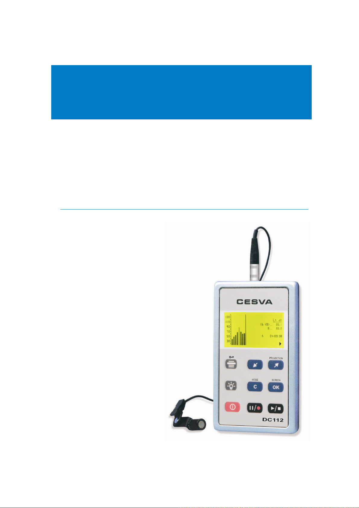
DC112d / DC112
Dosimeter / Dosimeter Spectrum Analyser
User’s Manual
M_DC112dDC112_v0035_20090923_ENG
Page 2

Page 3

DC112d/DC112
User’s manual
ENGLISH
1. GENERAL DESCRIPTION ..................................................................................................3
1.1 Activation of the frequency analysis in octaves module for the DC112d ........................4
1.2 Main Characteristics of the DC112d/DC112 ...................................................................4
1.3 Functions ........................................................................................................................5
1.4 Description of the DC112d/DC112..................................................................................6
1.5 Screen.............................................................................................................................8
1.6 Use of the keypad ...........................................................................................................8
2. USING THE DC112d/DC112 .............................................................................................10
2.1 Initial steps ....................................................................................................................10
2.1.1 Material and documentation ...................................................................................10
2.1.2 DC112d/DC112 Power source ...............................................................................10
2.1.3 Connection and disconnection of the microphone..................................................11
2.1.4 Fixing the DC112d/DC112 on the user (worker).....................................................12
2.2 Beginning a measurement ............................................................................................12
2.2.1 Switching on the DC112d/DC112 ...........................................................................12
2.2.2 Display screen selection .........................................................................................12
2.2.3 Testing the DC112d/DC112....................................................................................13
2.3 Measuring with the DC112d/DC112..............................................................................15
2.3.1 Prior adjustments....................................................................................................15
2.3.2 Beginning a measurement......................................................................................17
2.3.3 Function display......................................................................................................17
2.3.4 Blocking the keypad................................................................................................19
2.3.5 Interrupting the measurement.................................................................................19
2.3.6 Ending a measurement...........................................................................................20
2.3.7 Consulting measured data......................................................................................20
2.4 Overload indicator.........................................................................................................20
2.5 Menu of the DC112d/DC112: Register management and settings...............................20
2.5.1 Menu access...........................................................................................................20
2.5.2 Menu of the DC112d/DC112 ..................................................................................21
2.5.3 Register management ............................................................................................21
2.5.4 Settings...................................................................................................................22
2.6 Switching the DC112d/DC112 off .................................................................................22
3. REGISTERING DATA........................................................................................................23
3.1 Saving final results........................................................................................................23
3.2 Making a recording .......................................................................................................23
3.2.1 Continuing a recording after the DC112d/DC112 has been switched off ...............25
1
Page 4

3.3 Viewing the register ......................................................................................................25
3.4 Erasing the memory......................................................................................................25
4. DATA TRANSFER.............................................................................................................26
4.1 Transfer of data to a PC: Communication software ......................................................26
5. PRECAUTIONS AND WARNINGS ...................................................................................27
6. TECHNICAL SPECIFICATIONS .......................................................................................28
6.1 Measurement range......................................................................................................28
6.2 Peak detector - L
function ........................................................................................28
peak
6.3 Frequency weighting.....................................................................................................28
6.4 Sound pressure level range according to frequency.....................................................29
6.5 Octave band filters .......................................................................................................30
6.6 Microphone ...................................................................................................................30
6.7 Reference conditions ....................................................................................................31
6.8 Electrical signal insertion ..............................................................................................31
6.9 Single pole pulse response...........................................................................................31
6.10 Warm-up time .............................................................................................................31
6.11 Influence of temperature .............................................................................................31
6.12 Influence of humidity ...................................................................................................32
6.13 Influence of atmospheric pressure..............................................................................32
6.14 Electromagnetic compatibility......................................................................................32
6.15 Batteries and external supply......................................................................................33
6.16 Dimensions and weight...............................................................................................33
6.17 Calibration...................................................................................................................33
6.18 Standards....................................................................................................................33
6.19 Notes...........................................................................................................................34
6.20 Accessories.................................................................................................................34
7. Appendix A: Functions ....................................................................................................35
7.1 Definition of functions...................................................................................................35
7.1.1 Continuous equivalent sound pressure level ..........................................................35
7.1.2 Peak sound pressure level .....................................................................................35
7.1.3 Equivalent daily exposure level ..............................................................................35
7.1.4 Dose .......................................................................................................................36
8. Appendix B: Conditions of verification..........................................................................37
8.1 Verification procedures .................................................................................................37
8.1.1 Verification in units of sound exposure (Pa²h) ........................................................37
8.1.2 Verification in units of equivalent sound (Leq) ........................................................39
8.2 Alternative free-field method .........................................................................................43
2
Page 5

DC112d/DC112
User’s manual
1. GENERAL DESCRIPTION
The DC112 is a high performance dosimeter, in accordance with standards: IEC 61252:2002
and UNE-EN 61252:1998/A1:2003. Los dos modelos DC112d y DC112 disponen
exactamente de las mismas características como dosímetro. The difference between the two
models lies in the fact that only the DC112 is also a real time spectrum analyser in octave
bands with filters in accordance with IEC 61260:1995/A1:2001 and UNE-EN
61260:1997/A1:2002.
The DC112d/DC112 is the ideal instrument for measuring noise in accordance with Directive
2003/10/CE which adapts to recent technical progress, the regulation on the health and
safety requirements regarding the exposure of workers to the risks arising from noise. In The
Member States, this applies to the corresponding transposition to national law.
The DC112d can be converted into a DC112, for which it is necessary to acquire the module
EF112, either when purchasing the DC112, or subsequently. To acquire it, simply contact
your official CESVA distributor, give them the serial number of your SLM and place an order
for the module. Within a few days you will receive a CD containing the activation programme.
The DC112d/DC112 enables you to measure simultaneously all the parameters needed to
assess the levels of noise to which workers are exposed when wearing or not wearing
hearing protectors (SNR, HML).To do this it measures simultaneously the equivalent level
with A and C frequency weightings [ L
weighting A[ L
] (ISO 1999), Noise exposure in Pa2h [ E ] and noise dose [ DOSE ] with
EX,8h
respect to a programmable Criterion Level [ L
frequency weighting [L
] (ISO 1999).
Cpeak
, LCt ], daily noise exposure level with frequency
At
], and, of course, also the Peak Level with C
C
Moreover, the DC112d/DC112 allows you to carry out the measurement during a time
shorter than the exposure time, because it shows on the screen all parameters projected to
the expected exposure time (programmable projection time [ tp ] ).
To evaluate the exposure to noise, taking into account the attenuation of the individual
hearing protectors worn by the worker, the DC112, besides measuring the equivalent level
with A and C frequency weightings [ L
, LCt ] (SNR and HML method) like the DC112d,
At
simultaneously carries out a real time frequency analysis by octave bands from 63 Hz to 8
kHz (Octave method) with or without frequency weighting.
In line with the philosophy that characterises
instruments, the DC112d/DC112 is
a user-friendly instrument, with a single range, (no changes of scale), and simultaneous
measurement of all its parameters.
The large memory of the DC112d/DC112 allows you to store the time history of the
parameters measured (time periods longer than a week), and afterwards recalculate them for
any time interval required.
The DC112d/DC112 comes with the Capture Studio software. This application will enable
you to download measurements made with the instrument via the USB port, and analyse the
results quickly and simply.
The DC112d/DC112 does not only make the job of measuring and evaluating noise simpler,
it also brings you all the data needed to inform and train workers with regard to the
significance and potential risks arising from the results of the measurement and assessment.
Moreover, It helps you to design and run a noise reduction programme and to choose the
most suitable hearing protectors.
3
Page 6

1.1 Activation of the frequency analysis in octaves module for the
DC112d
NOTE
To activate the frequency analysis in octaves module for the DC112d (EF112):
• Insert the CD that you have received into the CD-ROM unit. The ‘EF112 module Activator’
• Follow the steps indicated.
: Once a module has been activated, it cannot be deactivated.
activation programme will run automatically. If this does not happen, run the SETUP.EXE
file of the CD-ROM unit.
1.2 Main Characteristics of the DC112d/DC112
• The DC112 carries out a frequency analysis in octave bands
exposure to noise, taking into account the reduction attained by the individual hearing
protectors used by the workers.
• The projection of parameters
measurement times less than the exposure time.
• The large memory (64 MB)
all the functions measured for long periods of time. The capacity is 1 month, saving
functions every second, irrespective of the number of measurements being saved.
• The DC112d/DC112 has a USB port
DC112d/DC112 is connected to the USB port of a PC it does not need batteries as it is
powered by the USB port of the PC.
• The keypad
the keypad is blocked, the values of the functions measured do not appear on the screen
to avoid the deliberate generation of noise to distort the measurements.
• The DC112d/DC112 adapts to any work shift
progress (pause), switch off
measurement (recording), making all the information available in just one measurement.
Ideal for measuring split shifts, and evaluating weekly levels.
• The graphic screen
spectral content
• The DC112d/DC112 has a register
in this way, any unauthorised manipulation is registered.
• The battery status
current state of the battery at all times.
• The DC112d/DC112 screen lights up at the touch of a button, meaning that work can be
carried out in atmospheres of poor lighting.
• The DC112d/DC112 supports multiple languages
• The DC112d/DC112 includes the Capture Studio
programmed
with data in electronic format, export
and graphic
• The DC112d/DC112 microphone
that they can carry out their working activities naturally.
• The DC112d/DC112 is a personal pocket-sized instrument. Its reduced weight and
robustness
workers whose work requires them to move about the workplace.
of the DC112d/DC112 can be blocked to avoid accidental interventions. While
is very practical for the evaluation of a noise event: its time history,
or its variability.
indicator that appears on the screen of the DC112d/DC112 shows the
and measurements can be downloaded. The software enables you to work
format, in order to create your own reports.
make it the ideal instrument for the evaluation of noise at work for those
makes it possible to evaluate the exposure to noise for
of the DC112d/DC112 enables you to save the time history of
to download data to a PC at high speed. While the
. As it allows you to stop a recording in
the instrument, switch it back on again later, and restart the
of the date of the last sensitivity adjustment carried out;
.
it to other programmes, and display it in numerical
incorporates a clip to attach it to the worker’s lapel so
(63 Hz to 8 kHz) to determine
software with which it can be
4
Page 7

DC112d/DC112
User’s manual
1.3 Functions
The DC112d/DC112 measures the following functions simultaneously in all the dynamic
range (one single scale):
• Equivalent continuous sound pressure level with A and C frequency weighting,
corresponding to the measurement time t, (L
• Peak sound pressure level with C frequency weighting corresponding to the measurement
time t, (L
Cpeak
).
• Equivalent continuous sound pressure level with or without A frequency weighting,
corresponding to measurement time t for each one of the octave bands centred on the
frequencies 63, 125, 250, 500, 1000, 2000, 4000 y 8000 Hz. (Only DC112).
• Equivalent daily exposure level corresponding to the measurement time t, (L
frequency weighting A.
• Sound exposure (E), corresponding to measurement time (t).
• Noise dose (DOSE), corresponding to measurement time t, evaluated according to the
criterion level (L
).
C
• Measurement time t.
• Projected equivalent daily exposure level (L
sound exposure (E
the projected time (t
), Projected noise dose (DOSEp) evaluated according to the value of
p
).
p
• Time history of the equivalent continuous sound pressure level with A frequency weighting
and integration time T.
Apart from the aforementioned functions corresponding to the measurement time, when it
carries out a recording, the DC112d/DC112 saves the time history of the following functions
every T period:
• Equivalent continuous sound pressure level with A and C frequency weighting,
corresponding to the integration time T, (L
• Peak sound pressure level with C frequency weighting corresponding to the integration
time T, (L
Cpeak,T
).
• Equivalent continuous sound pressure level with or without A frequency weighting,
corresponding to integration time T for each one of the octave bands centred on the
frequencies 63, 125, 250, 500, 1000, 2000, 4000 y 8000 Hz. (Only DC112).
y LCt).
At
EX,8hp
y LCT).
AT
) with
EX,8h
) with frequency weighting A, Projected
5
Page 8
1.4 Description of the DC112d/DC112
The most important parts of the DC112d/DC112 are detailed in the following diagram.
1. Microphone
2. Support clip
3. Microphone extension cable
microphone.
4. LEMO type microphone connector
Prepolarised lapel condenser microphone: P007.
. Adjustable clip to fix the microphone to a lapel or helmet.
. 1m flexible extension cable for the P007
P007 microphone.
5. LEMO type dosimeter connector
DC112d/DC112 dosimeter analyser.
6. Screen
7. Soft-touch membrane keypad
in industrial environments.
8. USB connector
communication.
9. Characteristics plate
the instrument complies are detailed.
10. CE mark
11. Serial number
12. Tripod support
. Backlit LCD graphic screen.
. Extra flat anti-dust keypad especially designed for work
. Mini-B type USB connector for full-speed bidirectional USB 1.1 digital
. On this plate the brand, model and all the standards with which
. European conformity mark.
. Here the dosimeter’s serial number is given.
. Tripod support with standard ¼’’ W screw. (TR-40 or TR050).
. Male LEMO type coaxial connector for the
. Female LEMO type coaxial connector for the
13. Support clip
14. WEEE mark
devices.
15. Battery protection cover
16. Manufacturer
. Support clip to attach the DC112d/DC112 to the worker’s belt.
. Symbol that indicates the selective collection of electric and electronic
. Here the details of the manufacturer are given.
. Cover for battery protection; only to be removed to change it.
6
Page 9

DC112d/DC112
User’s manual
1
2
3
6
7
4
5
9
10
11
12
13
14
8
15
16
7
Page 10
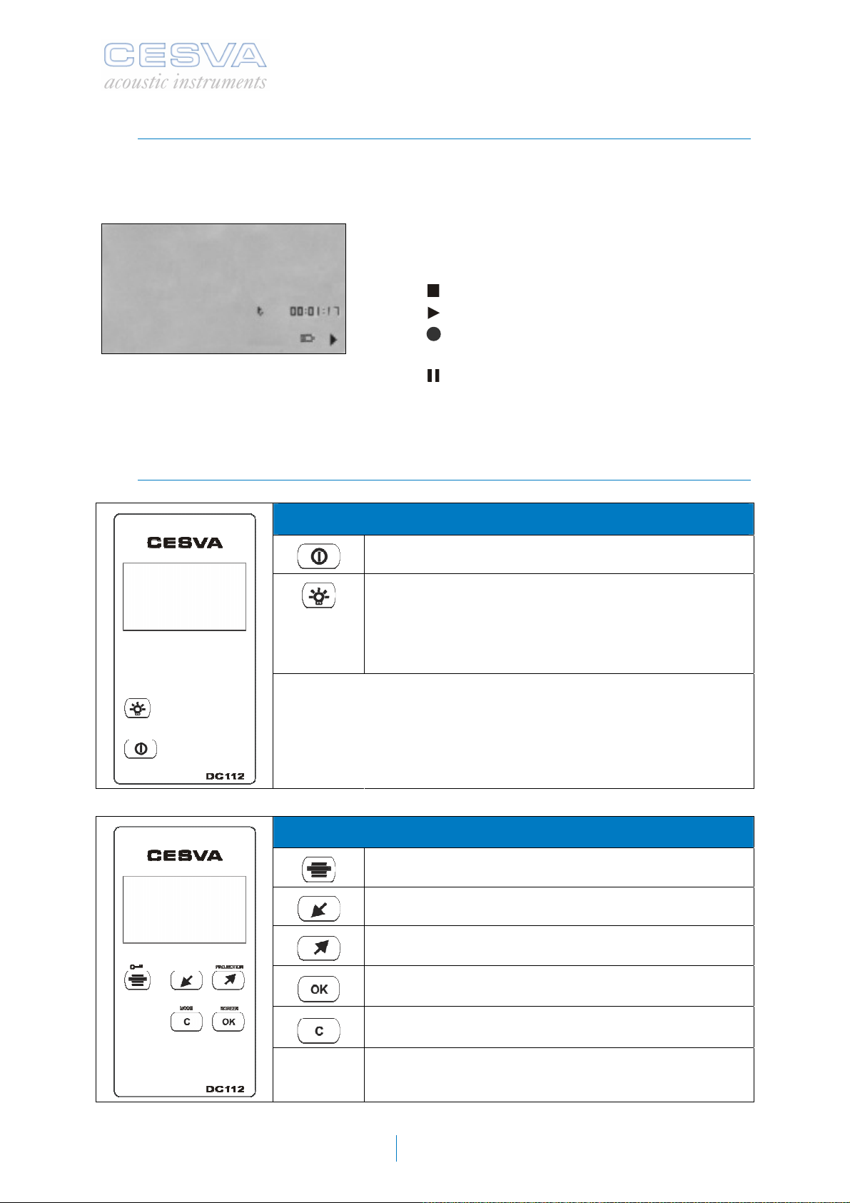
1.5 Screen
While the DC112d/DC112 is carrying out a measurement the following information is shown
in the bottom right-hand corner of the screen:
• Measurement time lapsed t
• Battery status indicator
• Measurement status indicator:
o measurement finished
o measurement in progress
o (flashing) measurement with recording in
progress
o measurement paused
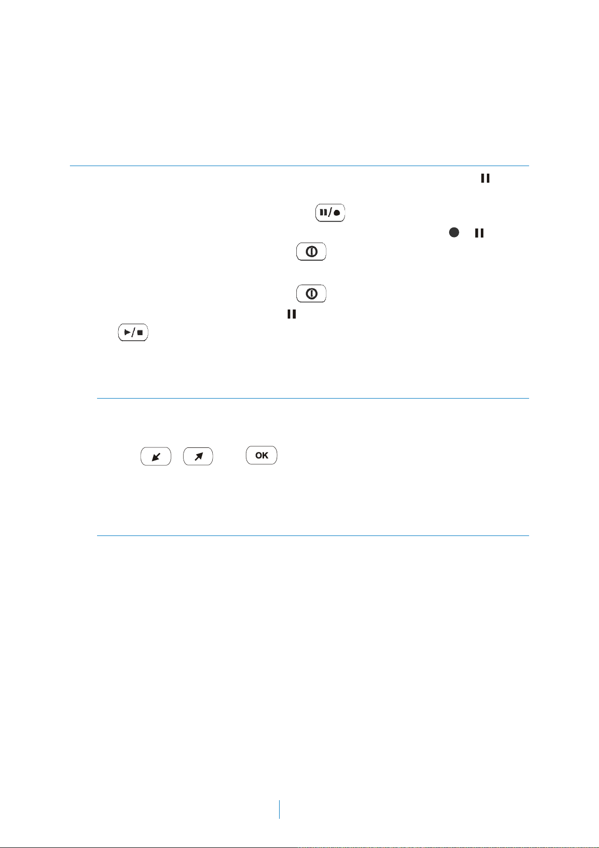
1.6 Use of the keypad
GENERIC KEYS:
On/Off key of the DC112d/DC112
On/Off key of the screen light. The light remains on for
five seconds, and then switches off automatically.
However, if the device is switched to the
DC112d/DC112 menu, the light will not switch off until
five seconds after exiting the menu.
MENU KEYS:
DC112d/DC112 menu access key
Key to move down the menu
Key to move up the menu
Key to validate or modify the selected option
Key to return to the previous menu or cancel
8
Page 11
DC112d/DC112
User’s manual
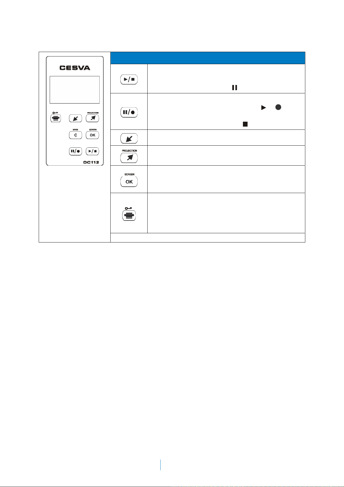
MEASUREMENT KEYS:
Key to return to the previous octave band
Key to move on to the next octave band, or to move
on to the numerical screen with projected parameters.
Key to select the desired Dosimeter mode screen:
numerical screen, 1/1 spectrum analyser screen or
graphic screen
a) Key to begin or end a measurement
b) Key to continue a measurement (when the
DC112d/DC112 is on
a) Key to interrupt (PAUSE) a measurement
(while the DC112d/DC112 is on
b) Or to begin a recording in the memory (when
the DC112d/DC112 is on
)
or )
)
Key to block the keypad. To unblock it press this same
key + OK.
9
Page 12

2. USING THE DC112d/DC112
2.1 Initial steps
This chapter contains all the information necessary to configure, adjust and carry out
measurements with the DC112d/DC112 dosimeter.
2.1.1 Material and documentation
The first step is to check the material and documentation provided with the DC112d/DC112:
Material included:
• DC112d/DC112 dosimeter spectrum analyser
• Case
• One 6LF22 type 9 V alkaline battery
• Connection cable for communication with the PC
• Capture Studio Software
Documentation included:
• User’s manual for the DC112d/DC112 dosimeter spectrum analyser
• Guarantee
If any of these elements should be missing, contact your official
distributor.
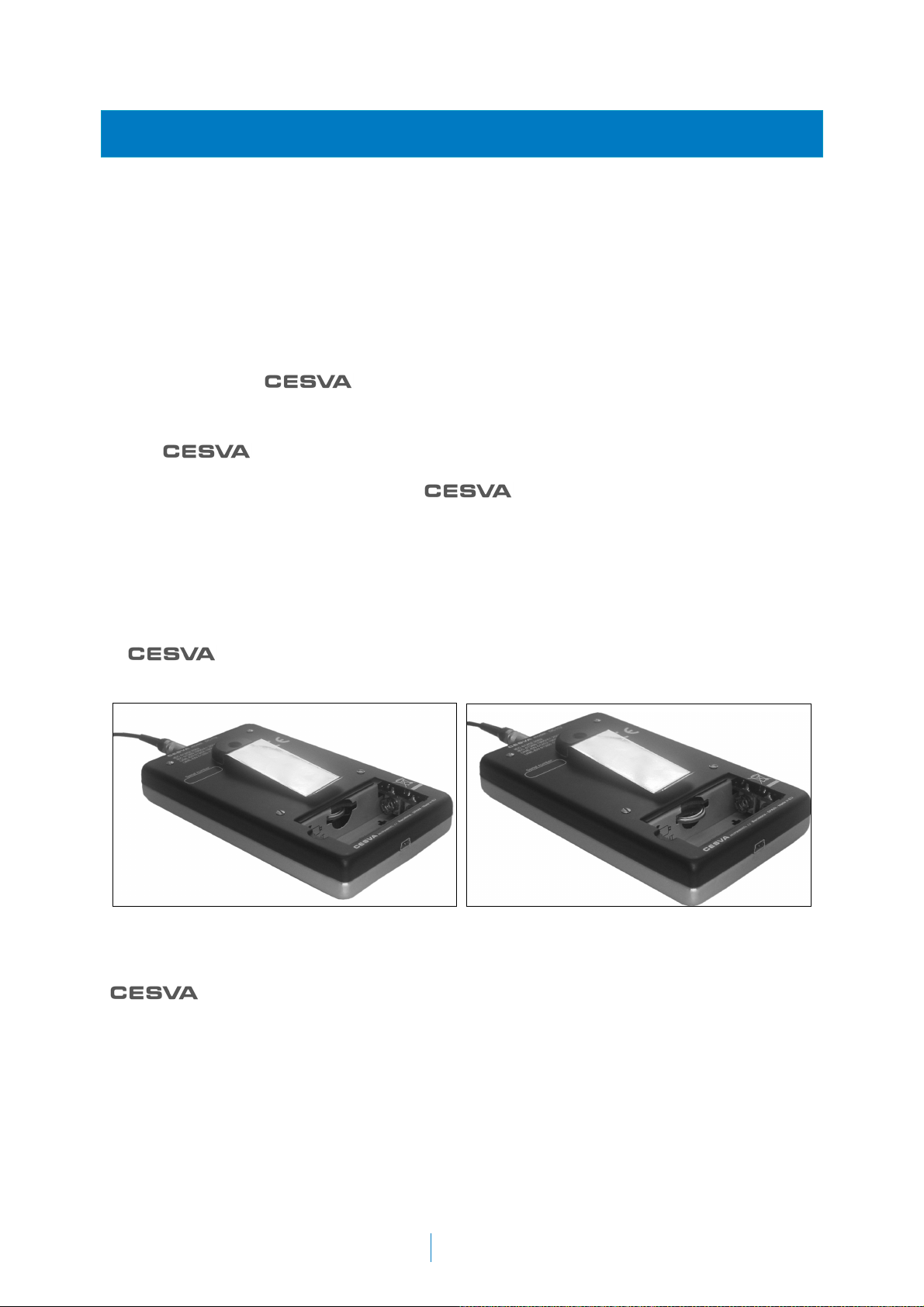
2.1.2 DC112d/DC112 Power source
The first operation to carry out, before switching on the DC112d/DC112, is to supply power.
The DC112d/DC112 dosimeter is
powered by a 6LF22 type 9V alkaline
battery, or via the USB port [
To fit the battery, remove the battery
protection cover [
at the back of the DC112d/DC112. Insert
the battery and press until the contacts fit
perfectly (see figure).
The battery indicator symbol in the bottom
right hand corner of the dosimeter screen
shows the status of the battery (see
figure).
When the battery is fully charged the
symbol shows on the screen. As the
battery is discharged, the symbol empties.
When the battery is not sufficiently charged for the
DC112d/DC112 to work correctly the
start to flash. Then, if there is a measurement or
recording in progress it will be paused, and the
message “BATTERY FLAT” will appear on the screen
and the device will switch off. The battery must be
replaced.
15] which can be found
8].
symbol will
To replace the batteries, the device must be switched off. To remove the battery of the
DC112d/DC112, open the battery compartment and pull upwards on the back of the battery,
as shown in the figure.
10
Page 13

DC112d/DC112
User’s manual
Once the batteries have been replaced,
simply switch on the device by pressing
and press to continue the
measurement.
The DC112d/DC112 can also be
powered via the USB port. To do this
connect the USB port of the
DC112d/DC112 [
8] to a USB port of a PC
with the cable provided. When it is
connected the
symbol will appear
where the battery symbol was.
RECOMMENDATIONS:
If the DC112d/DC112 is likely to be
unused for an extended period of time, remove the batteries from the DC112d/DC112 in
order to prevent damage caused by battery leakage.
We recommend that you always carry new replacement batteries
2.1.3 Connection and disconnection of the microphone
Before connecting or disconnecting the P007
microphone of the DC112d/DC112 dosimeter, make
sure the DC112d/DC112 is switched off.
To connect the microphone to the dosimeter, hold
the male plug of the microphone [
Insert it into the female socket [
and press until it clicks.
To disconnect the microphone, hold the male plug of
the microphone in the middle [ 4]. Pull upwards on
the plug until disconnects.
IMPORTANT: Do not pull on the end of the plug by
the cable, as it will not disconnect. Similarly, do not
try to disconnect it by twisting the plug. In both cases
the device could be damaged.
4] in the middle.
5] of the dosimeter,
11
Page 14

2.1.4 Fixing the DC112d/DC112 on the user (worker)
The DC112d/DC112 has a support clip [ 13] to fix it to the user’s belt (see figure) and an
adjustable metal clip [
Any excess wire should be wound in a figure 8.
2] to attach the microphone to their collar or helmet.
2.2 Beginning a measurement
2.2.1 Switching on the DC112d/DC112
To switch on the DC112d/DC112 press:
A screen will appear, showing the
After a few seconds the numerical screen of the DC112d/DC112 will appear (see
If the DC112d/DC112 fails to come on, check that it is correctly connected to a power source.
logo, along with the DC112d/DC112 model.
2.2.2).
2.2.2 Display screen selection
Once the dosimeter has been switched on it shows the numerical screen.
To change from one measurement screen to another, simply press
screen will appear.
and the new
12
Page 15

DC112d/DC112
User’s manual
The following are the screens of the DC112d/DC112:
NUMERICAL SCREEN
NUMERICAL SCREEN PROJECTED PARAMETERS
1/1 SPECTRUM ANALYSER SCREEN (Only DC112)
TIME HISTORY SCREEN
Numerical screen
1/1 Spectrum analyser screen (only DC112)
Numerical screen
projected parameters
Time history screen
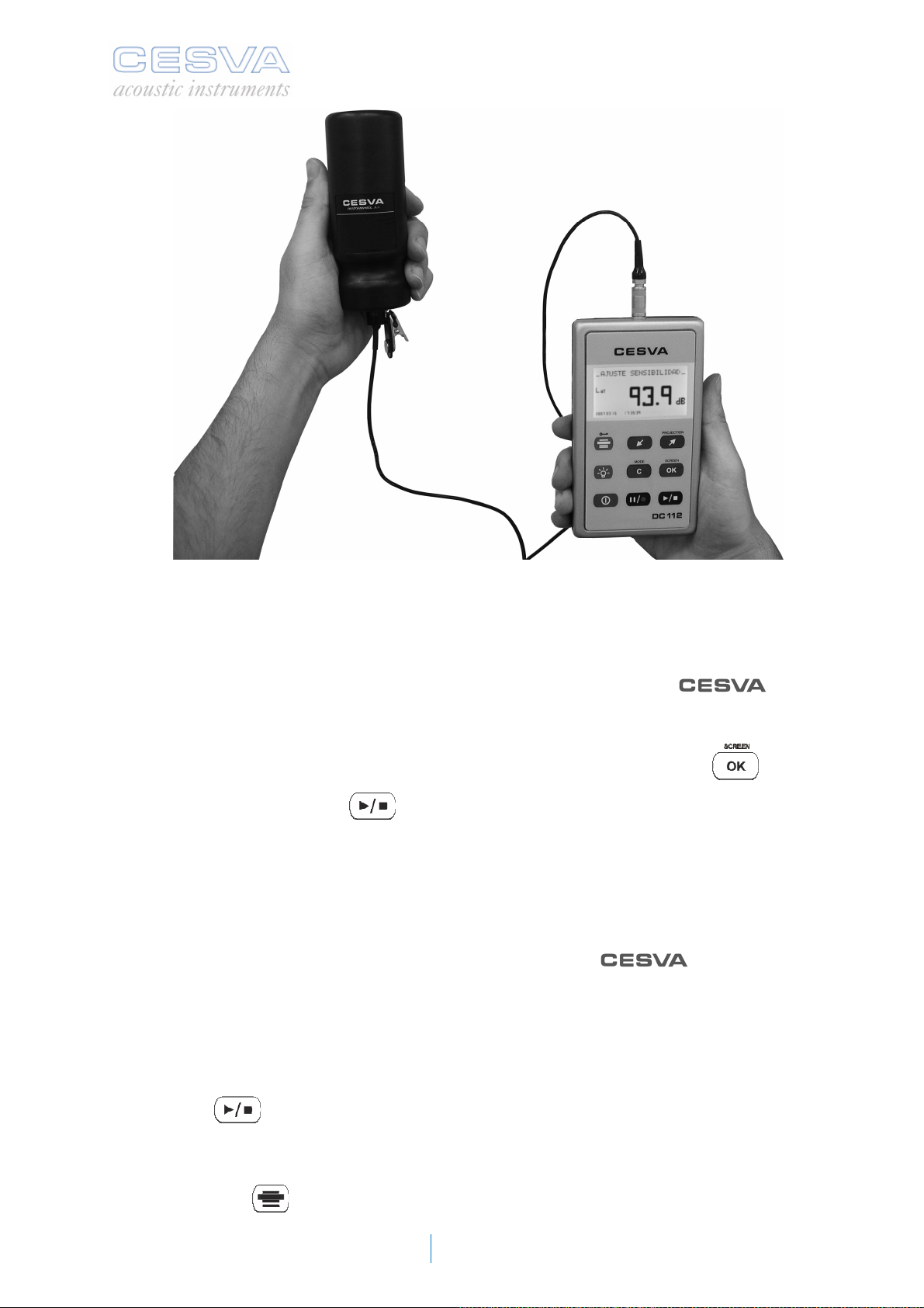
2.2.3 Testing the DC112d/DC112
We recommend that you test the DC112d/DC112 before beginning a measurement,
adjust the sensitivity (if necessary), and test it again after the measurement has
finished.
To test the DC112d/DC112 use the
proceed as follows:
1) Insert the microphone of the DC112d/DC112 in the cavity of the calibrator. Make sure
it has been fully inserted, and is parallel to the axis of the calibrator (see figure). This
may require a little force, as the microphone must fit into the calibrator perfectly. Do
not insert the DC112d/DC112 microphone roughly, as it may be damaged.
13
CB004 or CB006 sound calibrator and
Page 16
2) Switch on the calibrator and check the battery status. The indicator must be lit at all
times during the calibration process. The calibrator generates a tone of 94 dB at 1
kHz.
3) Apply the pressure to free field corrections to the microphone at 1 kHz and the
corresponding ones to the influence of atmospheric pressure, temperature and
humidity in the calibrator. The free field pressure correction of the
P007
microphone is 0.1 dB. That means the DC112d/DC112 should indicate a level of 93.9
dB.
4) Switch the DC112d/DC112 to the numerical screen (
5) Start the measurement:
6) Check that the value of the L
function coincides with the value of 94.0 dB with the
At
2.2.2), by pressing:
corresponding corrections (93.9 dB).
Should the value of the reading differ by more than ±0.3 dB from the calculated value, the
sensitivity of the dosimeter will need to be adjusted If not, the dosimeter is measuring
correctly, and the sensitivity does not need adjusting.
If the testing procedure is not satisfactory contact an official
service, before
adjusting it.
IMPORTANT: The sensitivity of the dosimeter must only be adjusted by authorised,
technically qualified personnel. Readjustment of the sensitivity entails the loss of traceability
in the calibration of the instrument.
To adjust the sensitivity, proceed as follows.
1) Press
to end the measurement process.
2) Do not switch off the CB004 (or CB006) calibrator, and keep it in the calibration
position.
3) Next press
to access the menu of the DC112d/DC112.
14
Page 17
DC112d/DC112
User’s manual
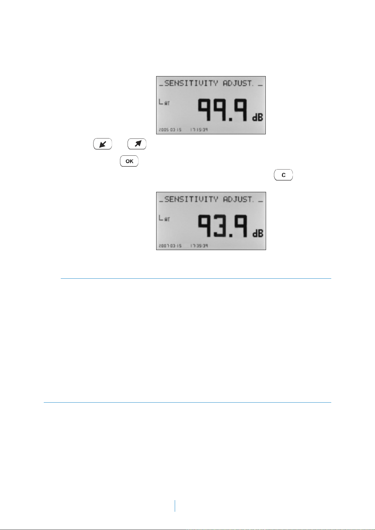
4) Access the option SETTINGS Î SENSITIVITY ADJUST.
5) The sound pressure level measured by the DC112d/DC112 will appear on the
screen, along with the time and date of the last time the sensitivity was modified.
6) Use the
7) Confirm with the
be updated). If you do not want update the sensitivity then press
and keys to adjust the value calculated (94 dB + corrections)
key (the sensitivity will be modified, and the time and date will
to return to
the DC112d/DC112 menu.
2.3 Measuring with the DC112d/DC112
The DC112d/DC112 measures the following parameters for the evaluation of noise at work:
equivalent daily exposure level (L
addition the DC112d/DC112 facilitates the projection of these parameters to the expected
exposure time (t
) for measurements shorter than the exposure time. It also measures the
p
equivalent continuous sound pressure level with A and C frequency weightings (L
the peak level with C weighting (L
Cpeak
), sound exposure (E) and noise dose (DOSE). In
EX,8 h
y LCt) and
At
).
Only the DC112 carries out a frequency analysis, measuring, in real time, the equivalent
continuous sound pressure levels for the octave bands between 63 Hz and 8 kHz with A
frequency weighting.
The time history analysis shows the evolution of the equivalent continuous sound pressure
level with and without A frequency weighting for the programmable continuous integration
time (T).
2.3.1 Prior adjustments
Before beginning a measurement, the following parameters should be set:
• Criterion level (L
noise DOSE
• Projection time (t
• Integration time (T). Integration time for the measurement of equivalent continuous sound
pressure level. The DC112d/DC112 saves the time history for the parameters (L
L
, and L
CT
• The frequency weighting applied to the spectrum measured.
Toct
), constant exposure to this level for eight hours would result in a 100 %
C
), predicted noise exposure time
p
).
15
Cpeak
, LAT,
Page 18
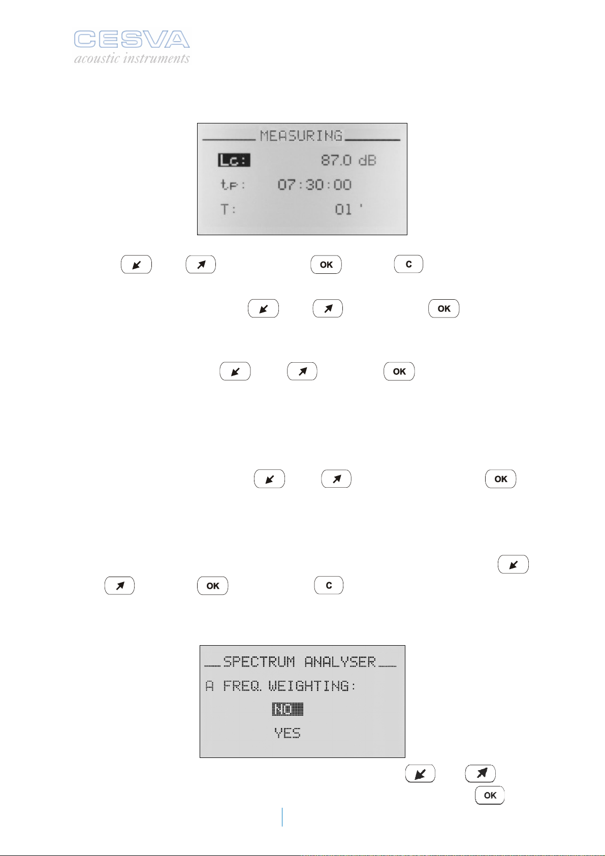
To set these parameters select the SETTINGS Î MEASURING Æ DOSIMETER option
from the DC112d/DC112 menu.
When the previous screen appears, select the parameter you want to configure L
, tp or T
C
using the
To modify the L
• Select the numerical value using and keys and press .
and keys, then press . Use the key to cancel.
parameter, proceed as follows:
c
To modify the t
• Set the hours value using and and press to confirm, repeat this
process to set the minutes value. The projection time t
parameter, proceed as follows:
p
is set from (HH:mm:00):
p
o 0 to 99 for HH (Hours)
o 0 to 59 for mm (minutes)
The minimum projection time is 1 minute.
To modify the T parameter, proceed as follows:
• Select the numerical value using and and confirm by pressing . T
integration time may be set from
o 1 to 59 seconds (1’’ – 59 ’’)
o 1 to 59 minutes (1’ – 59’)
o 1 to 99 hours (1H – 99 H)
• Finally select the time units: seconds (“), minutes (‘) or hours (H) with the help of
and
and press to confirm. Use to cancel or return to the menu.
To set the frequency weighting applied to the spectrum access the menu of the DC112 and
select SETTINGS Æ MEASURING Æ SPECTRUM ANALYSER
When the above screen appears, select YES or NO using the
depending on whether you wish to apply A frequency weighting or not, and press
and keys,
.
16
Page 19

DC112d/DC112
User’s manual
2.3.2 Beginning a measurement
First of all, ensure that the sound level meter has no measuring process in progress ( ). If it
has (
or ), press to stop it.
Next, set the DC112d/DC112 to dosimeter mode and choose the screen you want to display
(numerical, numerical with projected values, spectrum analyser or time history), with the
key.
Once you have selected your screen, press
to start the measurement process.
2.3.3 Function display
The DC112d/DC112 measures all functions simultaneously.
Described below are the different ways of displaying the acoustic functions for the
assessment of noise in the workplace while measurement is taking place. If you change the
kind of display (screen) or the octave band selected (spectrum analyser screen),
measurement will continue uninterrupted.
Numerical screen
This screen shows, in real time, the following information:
• Daily noise exposure level (L
• Sound Exposure (E).
• Noise dose (DOSE).
• Equivalent continuous sound pressure level with A and C frequency weightings
corresponding to the measurement time (L
• Peak sound pressure level with C frequency weighting corresponding to the measurement
time (L
• Criterion level (L
• Measurement time (t).
By pressing
Cpeak
).
)
C
the projected parameters are displayed.
) with frequency weighting A.
EX,8h
and LCt).
At
The projected parameters determine the sound exposure if the level measured remains
constant during the projection time.
The projected parameters allow the evaluation of the sound exposure for measurement times
shorter than the set projection time t
.
p
17
Page 20

• Projected daily noise exposure level (L
• Projected sound exposure (E
• Projected noise dose (DOSE
• Measurement time (t) and projected time (t
)
p
)
p
EX,8h p
) with frequency weighting A.
)
p
To return to the previous screen, press
.
When a register recovered from the memory is displayed on the screen, the sound level
meter uses the L
for a register according to the criterion level L
criterion level and the tp projection time set. This feature allows evaluations
C
and the projection time tp set on the sound
C
level meter.
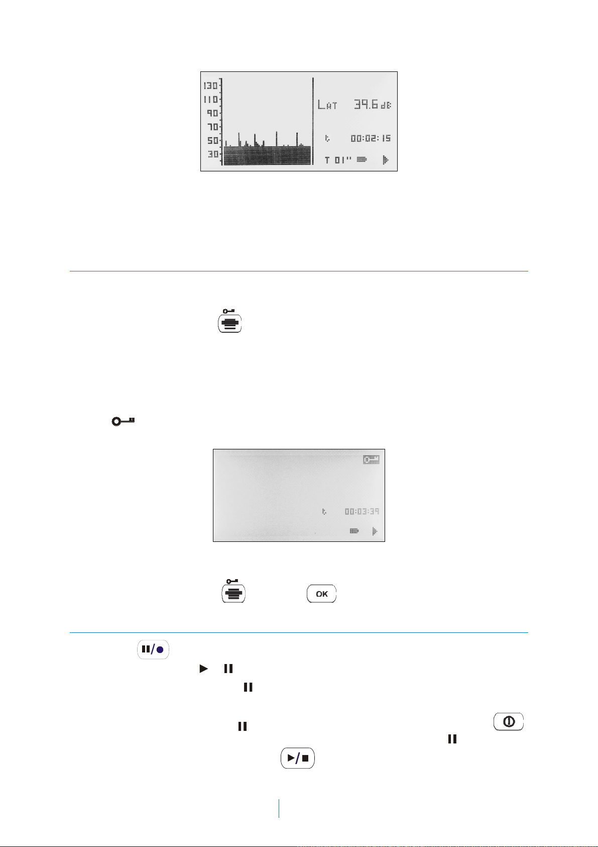
1/1 Spectrum analyser screen (only DC112)
This screen shows, in real time, the following information:
• Graph of the equivalent continuous sound pressure level with the integration time
corresponding to the measurement time (
bars) in real time for the octave bands centred
on frequencies 63, 125, 250, 500, 1000, 2000, 4000 and 8000 Hz (with A frequency
weighting).
• Numerical value of the equivalent continuous sound pressure level with the integration
time equal to the measurement time for the selected octave band (
bar) (with A frequency
weighting).
• Central frequency of the selected octave band ( bar)
• Overall equivalent continuous sound pressure level with the integration time corresponding
to the measurement time and with A frequency weighting.
• Measurement time (t)
Time history screen
This screen shows, in real time, the following information:
18
Page 21
DC112d/DC112
User’s manual
• Time history (60 values) of the equivalent continuous sound pressure level with integration
time (T) and A frequency weighting.
• Numerical value of the equivalent continuous sound pressure level with integration time
(T) and A frequency weighting.
• Measurement time (t) and integration time elapsed.
2.3.4 Blocking the keypad
While a measurement or recording is in progress, the keypad of the DC112d/DC112 can be
blocked; this way accidental interventions in the process can be avoided.
To block the keypad, press
. The message KEYPAD BLOCKED will appear on the
screen.
Next, the information of the functions measured will disappear from the screen, leaving just:
• The measurement time (t) elapsed
• The battery status indicator
• The measurement status indicator
• The symbol in the top right-hand corner of the screen, indicating that the keypad is
blocked
While the keypad is blocked, the values of the functions measured do not appear on the
screen, to avoid the deliberate generation of noise to distort the measurement.
To unblock the keypad, press
followed by .
2.3.5 Interrupting the measurement
By pressing you temporarily interrupt the measurement. The measurement status
indicator will change from
While a measurement is paused ( ) you may continue to consult the functions measured
prior to the temporary interruption of measurement.
While a measurement is paused (
When it is switched on again, the measurement will remain on pause (
resumed. To resume measurement, press
to .
) the device can be switched off. To do this press .
) and can be
.
19
Page 22

This characteristic of the DC112d/DC112 allows measurements to be carried out for workers
with split shifts or special shifts (eg. weekends). It also enables the battery to be changed
without the need to make two measurements.
2.3.6 Ending a measurement
By pressing you end the measurement or recording. The measurement status
indicator will change from
to .
2.3.7 Consulting measured data
While the DC112d/DC112 is not measuring ( ), you may consult all the functions measured.
To consult them, apply the same procedure as described in section
measurement is in progress.
0 on viewing data while
2.4 Overload indicator
The DC112d/DC112 is equipped with an overload indicator for each function. If overloading
occurs during a measurement, the ^ symbol will appear before the function affected by
overloading. When a function registers overload its corresponding measurement may be
incorrect.
During the overload the
indicator appears in the bottom right-hand corner of the screen.
2.5 Menu of the DC112d/DC112: Register management and settings
This section details the options that are accessible from the DC112d/DC112 menu, among
them; memory management, setting the measurement parameters, setting the language, the
time and date and, only in the DC112 selection of frequency weighting for the spectrum
analyser.
The DC112d/DC112 comes with an initial configuration which makes it possible to carry out
measurements without having to reset it in advance.
2.5.1 Menu access
To access the DC112d/DC112 menu, make sure that no measurement is in progress ( )
and press
The following screen will appear:
.
20
Page 23

DC112d/DC112
User’s manual
This menu shows the main settings screen along with the time and date of the
DC112d/DC112’s clock. The memory status is also shown, indicating the available memory
remaining.
• Memory empty Î
• Memory full Î
2.5.2 Menu of the DC112d/DC112
The memory of the DC112d/DC112 has the following structure
(only DC112)
To move through the settings menu use the keys described in section 1.6.
2.5.3 Register management
• SAVING RESULTS:
When this option is selected the DC112d/DC112 records in its memory the final results of
all the functions measured. The DC112d/DC112 indicates the number of the register in
which the registers have been recorded. For more information see section
• MEMORY:
This option facilitates the management of the DC112d/DC112 memory.
MEMORY Î VIEW REGISTER
Shows the registers recorded in the dosimeter. For more information see section
3.3.
MEMORY Î ERASE MEMORY
3.4.
This option erases the memory of the DC112d/DC112 completely. All the registers
stored in the memory (results and recordings) will be deleted. For more information see
section
3.4.
21
Page 24

2.5.4 Settings
• SETTINGS:
This option enables you to set a number of features of the DC112d/DC112, eg. Time/date
adjustments, language or sensitivity of the DC112d/DC112.
SETTINGS Î MEASURING
With this option the acoustic parameters for the evaluation of noise at work: level
of criterion L
SETTINGS Î MEASURING (only DC112)
• DOSIMETER.
With this option the acoustic parameters for the evaluation of noise at work are
defined; criterion level L
• SPECTRUM ANALYSER.
Allows to select the frequency weighting (A or without) which will be used for the
spectrum analyser(see 2.3.1).
SETTINGS Î SENSITIVITY ADJUST:
This option enables you to adjust the sensitivity of the DC112d/DC112. For more
information see section
SETTINGS Î LANGUAGE
Allows the language to be selected in which all the messages and menus of the
projection time tp and integration time T are defined (see 2.3.1).
C,
projection time tp and integration time T (see 2.3.1).
C,
2.2.3 Testing the DC112d/DC112.
DC112d/DC112 are displayed. Select the language with
and .
SETTINGS Î TIME AND DATE
This option allows the time and date of the DC112d/DC112 to be adjusted.
2.6 Switching the DC112d/DC112 off
To switch off the DC112d/DC112, check that no measurement is in progress ( ) and
press:
.
22
Page 25

DC112d/DC112
User’s manual
3. REGISTERING DATA
The DC112d/DC112 can record in the internal memory the values of the functions measured.
When the equipment is switched off the recorded data is not lost and can be retrieved and
displayed directly from the DC112d/DC112 or transmitted to a PC. The memory can be
erased directly from the DC112d/DC112.
Two kinds of registers may be saved in the memory:
• The final results of a measurement.
• Continuous recordings of functions with programmable integration time.
3.1 Saving final results
Once you have completed a measurement ( ), the results may be stored in the memory by
selecting the SAVE RESULTS option from the main menu. The DC112d/DC112 will indicate
the register number in which to save the data.
The DC112d/DC112 stores the following information.
• Equivalent continuous sound pressure level with A frequency weighting corresponding to
the measurement time (t) (L
• Equivalent continuous sound pressure level with C frequency weighting corresponding to
the measurement time (t) (L
• Equivalent continuous sound pressure level with the integration time corresponding to the
measurement time (t), with or without A frequency weighting for each one of the octave
bands centred on frequencies 63, 125, 250, 500, 1000, 2000, 4000 and 8000 Hz. (Only
DC112).
• Overall peak sound pressure level with C frequency weighting corresponding to the
measurement time t (L
• Equivalent daily noise exposure level (L
• Equivalent continuous sound pressure level with A frequency weighting corresponding to
Cpeak
the last integration interval (T) (L
• Equivalent continuous sound pressure level with C frequency weighting corresponding to
the last integration interval (T) (L
• Equivalent continuous sound pressure level corresponding to the last integration interval
(T), with or without A frequency weighting for each one of the octave bands centred on
frequencies 63, 125, 250, 500, 1000, 2000, 4000 and 8000 Hz.(Only DC112)
• Peak sound pressure level of the integration interval (T) with C frequency weighting.
• Measurement time (t), integration time (T) and the integration time elapsed.
• Date and time of the beginning of the measurement.
DOSE, DOSE
p
, L
, E and Ep functions are not saved. Every time a register is displayed
EX,8h p
with the MEMORYÎ SEE REGISTER option, these functions are calculated according to the
L
and tp values.
C
).
).
At
).
Ct
).
EX,8h
).
AT
).
CT
3.2 Making a recording
A recording consists of making a measurement and storing the parameters measured by the
DC112d/DC112 in the memory.
Before beginning a recording, make sure there is no measurement in progress (
To begin a recording, press
. The screen will display the register number. The
functions selected for the type of recording will be saved periodically in the memory until you
stop the recording by pressing
.
23
).
Page 26
During the recording process the recording icon ( ) will appear on the screen.
The DC112d/DC112 saves the following values once each integration period (T) has
finished:
• Equivalent continuous sound pressure level with A frequency weighting (L
• Equivalent continuous sound pressure level with C frequency weighting (L
• Equivalent sound pressure level corresponding to the last T integration interval, with or
AT
CT
).
).
without frequency weighting (A) for each one of the octave bands centred on frequencies
63, 125, 250, 500, 1000, 2000, 4000 and 8000 Hz. (Only DC112)
• Peak sound pressure level of the T integration interval with C frequency weighting (L
).
T
Cpeak,
When the measurement ends, the final results are saved:
• Equivalent continuous sound pressure level with A frequency weighting corresponding to
the measurement time (L
• Equivalent continuous sound pressure level with C frequency weighting corresponding to
the measurement time (L
• Equivalent continuous sound pressure level with the integration time corresponding to the
).
At
).
Ct
measurement time, with or without A frequency weighting for each one of the octave bands
centred on frequencies 63, 125, 250, 500, 1000, 2000, 4000 and 8000 Hz. (Only DC112).
• Overall peak sound pressure level with C frequency weighting corresponding to the
measurement time (L
• Equivalent daily noise exposure level (L
Cpeak
).
EX,8h p
).
a) Equivalent continuous sound pressure level with A frequency weighting corresponding to
the last integration interval (T) (L
• Equivalent continuous sound pressure level with C frequency weighting corresponding to
the last integration interval (T) (L
• Equivalent continuous sound pressure level corresponding to the last integration interval
CT
).
AT
).
(T), with or without A frequency weighting for each one of the octave bands centred on
frequencies 63, 125, 250, 500, 1000, 2000, 4000 and 8000 Hz. (Only DC112)
• Peak sound pressure level of the integration interval with C frequency weighting (L
• Measurement time (t), integration time (T) and the integration time elapsed.
• Date and time of the beginning of the measurement.
DOSE, DOSE
p
, L
, E and Ep functions are not saved. Every time a register is displayed
EX,8h p
Cpeak
).
via the MEMORY Î SEE REGISTER option, these functions are calculated according to the
L
and tp.
C
The storage capacity according to the programmable integration time is shown in the
following table.
Storage capacity
T= 1 s 1 month 3 days
T= 10 s 11 months 7 days
The storage times for each type of recording correspond to one single recording, until the
memory is completely full.
When the built-in memory is full, no more recordings can be made and no more final results
saved. If you attempt to do this, the ‘MEMORY FULL’ message will appear on screen.
If the battery of the DC112d/DC112 runs out during a recording, the DC112d/DC112 will
interrupt the recording (PAUSE), show the message “BATTERY FLAT” on the screen and
switch off. To continue the measurement, see section
3.2.1.
If the power source of the DC112d/DC112 is cut off suddenly during a recording, (removal of
the battery, or the USB connection), the recording will be incomplete. It will not be able to be
24
Page 27
DC112d/DC112
User’s manual
viewed with the DC112d/DC112; the message “RECORDING INCOMPLETE” will appear on
screen when this is attempted. However it will be possible to download it to a computer using
Capture Studio. Following these measurements, more registers can be recorded as long as
the capacity allows.
3.2.1 Continuing a recording after the DC112d/DC112 has been
switched off
The DC112d/DC112 allows for a recording that has been interrupted (pause ) to be
continued after switching off the dosimeter. To do this, proceed as follows:
• Interrupt the recording in progress by pressing .
• The recording will stop and the recording status indicator will change from to .
• Switch off the DC112d/DC112 by pressing .
When you wish to restart the measurement
• Switch on the DC112d/DC112 by pressing .
• The measurement will appear on pause ( ).
• Press to continue the measurement. The DC112d/DC112 will continue saving the
values measured in the same register.
3.3 Viewing the register
This option allows you to display on screen the final result of the registers stored in the
DC112d/DC112 memory. Access the option by selecting MEMORY Î VIEW REGISTER
from the DC112d/DC112 menu.
By pressing
register you want to view. The screen will display an index of all the registers stored in the
memory (register number + date and time when the measurement process began).
To view the different functions, follow the procedure described in section
, and , the DC112d/DC112 allows you to select the
2.3.3.
3.4 Erasing the memory
This option enables you to wipe the memory completely. The DC112d/DC112 asks for
confirmation before erasing. MEMORY Î ERASE MEMORY.
25
Page 28

4. DATA TRANSFER
The DC112d/DC112 has the following data outputs (see figure).
• USB communications port
with a personal computer
The USB communication port allows real time transmission of the functions measured and
those saved in the memory of a computer with a high transfer speed
: bidirectional digital USB 1.1 full speed port for communication
4.1 Transfer of data to a PC: Communication software
The communication software supplied with the DC112d/DC112 ( Capture
Studio), allows the following operations to be carried out:
• Real time transmission of the data measured by the DC112d/DC112 to a computer.
• Downloading the registers saved by the DC112d/DC112.
• Register management (erasing, etc.).
• Programming the dosimeter (time, parameters, etc.).
To carry out these functions the DC112d/DC112 must be connected to the USB port of a
computer with the cable supplied.
For more information about
Capture Studio, use the help that it incorporates.
26
Page 29
DC112d/DC112
User’s manual
5. PRECAUTIONS AND WARNINGS
• Keep the microphone away from dust and sharp objects.
• Avoid excessive humidity and sudden changes of temperature which may produce
condensation on the microphone.
• The microphone must never be dismantled, as this may cause permanent damage.
• Any knocks on the DC112d/DC112 will be picked up by the microphone, and this may
affect the value of the measurement.
• We recommend that you test the DC112d/DC112 before and after every measurement,
using the sound calibrator. See section
contact an official
• Remove the batteries if the DC112d/DC112 will not be used for an extended period of
time.
• The
If any malfunction cannot be resolved by changing the battery or consulting the manual,
send the DC112d/DC112 to an official
it to be repaired by unauthorised personnel.
• The DC112d/DC112 has an internal clock powered by a 3 V CR2032 type lithium button
battery which enables it to save the time and programme. This lithium battery has an
average lifespan of 10 years. When it runs out, the internal calendar/clock returns to 00:00
on the 01/01/2000. Go to the menu of the DC112d/DC112 to consult the calendar. The
battery must be replaced immediately: Remove it from the slot which is accessed from the
battery compartment (see photo) and replace it with a new one, or contact your official
DC112d/DC112 dosimeter is designed to be very reliable for a long time.
technical service.
service, before adjusting it.
2.2.3. If the testing procedure is not satisfactory
service. Under no circumstances allow
This equipment can only be used with the accessories specified in the Accessories section. If
any unauthorised accessories are used, and this results in a failure of the equipment,
will not accept responsibility for this failure, and the equipment will be out of
warranty.
27
Page 30
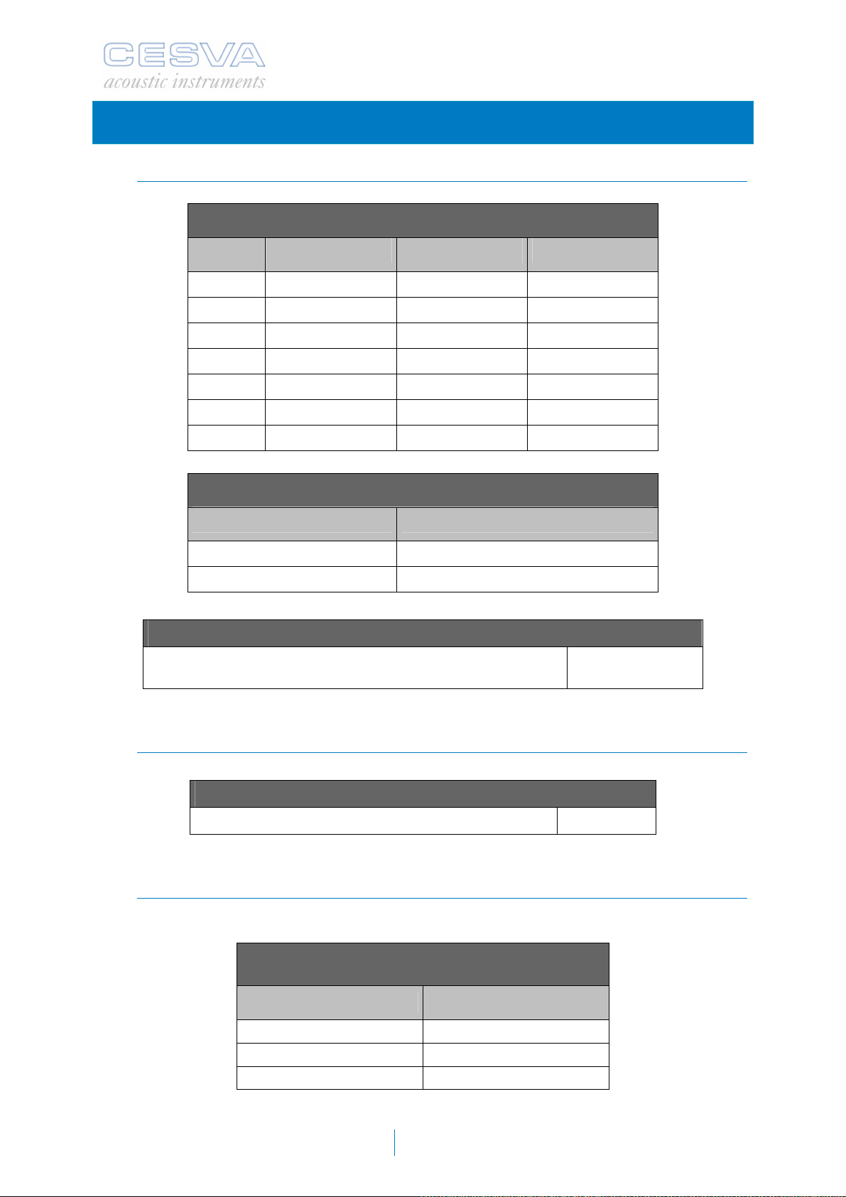
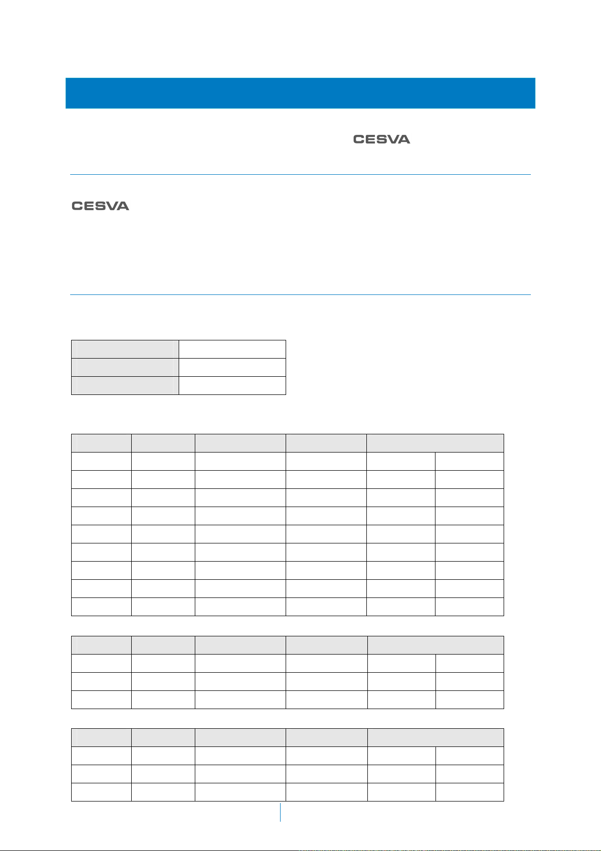
6. TECHNICAL SPECIFICATIONS
6.1 Measurement range
Measurement range
Function Lower limit Upper limit Units
t 0000:00:00 1999:59:59 HHHH:MM:SS
E 0 9999999 Pa2h
LAt 50 140 dB
LCt 60 140 dB
L
70 143 dB
Cpeak
DOSE 0 9999999 %
L
0 999,9 dB
EX,8h
Total Maximum Noise at 20 ºC
Frequency Weighting Total Maximum Noise
Margin of frequencies maintained when the frequency response
extends to frequencies below 63 Hz or above 8 kHz
6.2 Peak detector - L
Onset time constant:
6.3 Frequency weighting
A 43 dB
C 53 dB
31,5 Hz a 12,5 Khz
function
peak
< 75 µs
Frequency weightings available
Function
L
peak
L
T
L
t
Weighting
C
A and C
A and C
28
Page 31
DC112d/DC112
User’s manual
The following table shows the A and C frequency weightings along with their
tolerance.
Frequency
(Hz)
63 - 26,2 - 0,8
125 - 16,1 - 0,2
250 - 8,6 - 0,0
500 - 3,2 - 0,0
1,000 0 0
2,000 + 1,2 - 0,2
4,000 + 1,0 - 0,8
8,000 - 1,1 - 3,0
A Weighting
(dB)
C Weighting
(dB)
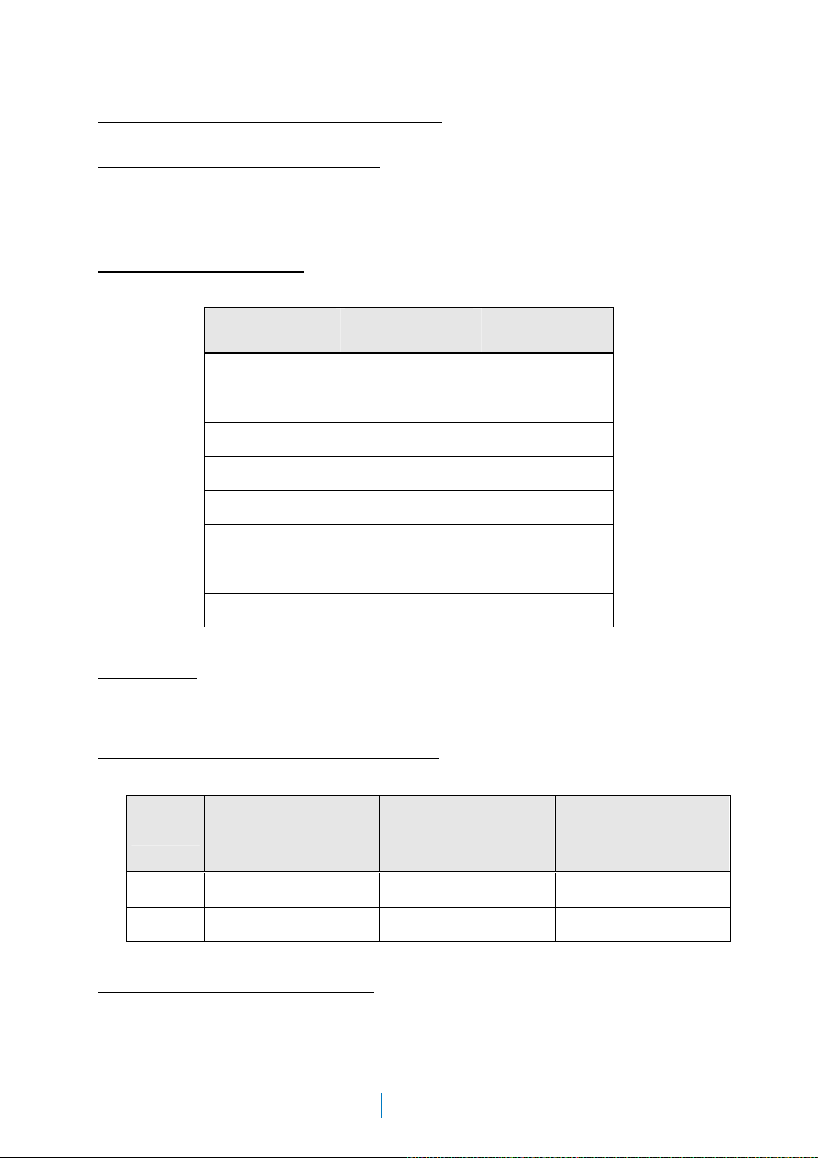
6.4 Sound pressure level range according to frequency
Typical values for A weighting frequency
Frequency
(Hz)
Maximum level
(dB)
Minimum level
Tolerance
(dB)
± 2,0
± 1,5
± 1,5
± 1,5
± 1,5
± 2,0
± 3,0
± 5,0
(dB)
63 113,8 50
125 123,9 50
250 131,4 50
500 136,8 50
1,000 140,0 50
2,000 140,0 50
4,000 140,0 50
8,000 138,9 50
Typical values for C weighting frequency
Frequency
(Hz)
63 139,2 60
125 139,8 60
250 140,0 60
500 140,0 60
1,000 140,0 60
Maximum level
(dB)
Minimum level
(dB)
2,000 139,8 60
4,000 139,2 60
8,000 137,0 60
29
Page 32
6.5 Octave band filters
Frequency evaluation system Base 10
Reference attenuation 0 dB
Margin of frequencies for real time operation 31,5 Hz a 16 kHz
Nominal central frequency Exact central frequency
63 Hz 63,096 Hz
125 Hz 125,89 Hz
250 Hz 251,19 Hz
500 Hz 501,19 Hz
1 kHz 1.000 Hz
Octave band central frequencies
2 kHz 1.995,3 Hz
4 kHz 2.511,9 Hz
8 kHz 7.943,3 Hz
6.6 Microphone
Prepolarised ½” condenser microphone with preamplifier incorporated
Nominal sensitivity (typical) 11,2 mV/Pa
Length of cable 1 m
Frequency (Hz) Correction (dB) Frequency (Hz) Correction (dB)
P007
Constant pressure to free field correction
63 0.5 1.000 0.1
125 0.0 2.000 0.4
250 0.1 4.000 1.3
500 0.0 8.000 4.1
Typical frequency response
Frequency
(Hz)
63 1.3 1.000 0.0
125 0.5 2.000 0.0
250 0.3 4.000 0.4
500 0.1 8.000 0.4
Relative response
(dB)
Frequency
(Hz)
Relative response
(dB)
30
Page 33

DC112d/DC112
User’s manual
6.7 Reference conditions
Type of sound field: Free
Reference direction Perpendicular to the microphone
Reference frequency: 1 kHz
diaphragm
Reference sound pressure level:
Reference integration time: 1 hour
Reference sound exposure: 1,0 Pa2h
6.8 Electrical signal insertion
Can be carried out with a Coaxial LEMO [5] connector situated at the top of the
DC112d/DC112. The ADM0P007 adapter must be used.
The devices connected must have an electrical impedance of less than 100 Ω.
6.9 Single pole pulse response
Typical E deviation with positive and negative
pulses
94 dB (ref a 20 µPa)
0 %
6.10 Warm-up time
Warm-up time 30 seconds
6.11 Influence of temperature
Operation range 0 a +40 °C
Storage without batteries -20 a +60 °C
31
Page 34

6.12 Influence of humidity
Operation range: 30 to 90 %
Storage without batteries: < 93 %
6.13 Influence of atmospheric pressure
Operation range: 91,2 a 111,4 kPa
6.14 Electromagnetic compatibility
Configuration for the normal operation
mode.
Numerical screen in dosimeter mode,
and with Lc = 87dB
Influence of Magnetic Fields In a magnetic field of 80 A/m (1
oersted) at 50 Hz, the reading will be
under 52 dB(A). With the instrument
positioned perpendicular to the
magnetic field propagation direction
and the microphone cable extended
around the instrument. In addition the
USB communication cable without
connector will be connected.
LAt Sound pressure level at which the
DC112d/DC112 meets the requirements
of a radiated electromagnetic field.
Set of accessories tested in the
verification of the electromagnetic
compatibility requirements.
Configuration for the reference
orientation.
No emission difference is observed from the normal operation mode with the equipment
in a vertical position, with the microphone cable fully extended perpendicular to the main
axis of the DC112d/DC112 with all cables connected and with the USB feeder
74 dB
P007 Microphone and USB connection
cable (CN1US)
DC112d/DC112 perpendicular to the
ground, and the microphone following
the main axis of the dosimeter, with
50cm of cable extended, and any
excess cable wound in a figure 8.
The equipment shows no degradation or loss of function after being exposed to
electrostatic discharges.
The DC112d/DC112 shows a slight variation with respect to the electric field with the
instrument perpendicular to the propagation direction and the cables extended
perpendicular to the main axis of the instrument
The application of sinusoidal vibrations of 1 m/s2 between 20 Hz and 1000 Hz does not
limit the operation of the instrument.
32
Page 35

DC112d/DC112
User’s manual
6.15 Batteries and external supply
Battery
One 6LF22 type 9 volt battery
Typical battery life with continuous use:
The typical battery life with the display lit may be reduced by
up to 50% with respect to the previous value
External Supply
By USB port
6.16 Dimensions and weight
Dimensions: 144 x 82 x 23 mm
Weight: With battery 361 g
6.17 Calibration
20 hours
Without battery 320 g
Use the CB004 or CB006 calibrator and consult section 2.2.3.
6.18 Standards
Standards
UNE-EN 61252:1998/A1:2003; UNE-EN 61260:1997/A1:2002
EN 61252:1995/A1:2001; EN 61260:1995/A1:2001
IEC 61252:2002 ; IEC 61260:1995/A1:2001
DIRECTIVE 2003/10/CE OF THE EUROPEAN PARLIAMENT AND OF THE COUNCIL of
6 February 2003 on the minimum requirements for the health and safety related to the
exposure of workers to risks derived from physical agents (noise)
latter amended by 93/68/CEE.
gives notice that the product you have purchased was put on the market later than 13
August 2005 and complies with 2002/96/CE and 2003/108/CE directives on Waste from
Electrical and Electronic Equipment (WEEE).
mark. Complies with 73/23/CEE and CEM 89/336/CEE low-tension regulations, the
as manufacturer of electric or electronic equipment
In addition, the product is marked with the following symbol, which indicates
that it is subject to separate collection.
33
Page 36

6.19 Notes
Notes
Should your DC112d/DC112 cease to comply with any of these specifications, contact your
nearest official
it for you.
It is obligatory to send the DC112d/DC112 to an authorised laboratory annually, to test its
acoustic and electric characteristics are working correctly (periodic testing).
6.20 Accessories
Standard accessories
FNS-011 Case
SFT030 Computer programme
CN1US Connection cable
service technicians, who will gladly check, adjust and/or repair
9 volt battery
Optional accessories
CB004 Class 2 acoustic calibrator
TR-40 Tripod: Max height 1,2 m
TR050 Tripod: Max height 1,5 m
ML-50 Carrying case (49x36x14 cm)
ML-10 Carrying case (39x32x12 cm)
ML060 Special outdoors briefcase (51x38x15 cm)
A-200 Mains feeder 230V to 9V
A-100 Battery converter 12V to 9 V
PB009 Rechargeable 9 V 200 mA battery
CP009 Charger for 9 V 200 mA batteries
34
Page 37

DC112d/DC112
+
=
User’s manual
7. Appendix A: Functions
7.1 Definition of functions
7.1.1 Continuous equivalent sound pressure level
LT and Lt This is the linear average of the instantaneous sound pressure square from
the beginning (t
pt: instantaneous sound pressure
p
) to the end (t2.) The duration of the measurement is therefore T= t2 - t1
1
t
2
⎛
⎜
⋅=
eqT
log10L
⎜
⎝
: reference sound pressure (20 µPa)
0
2
⎞
(t)p
1
∫
T
p
t
1
⎟
dt
2
⎟
0
⎠
T: duration of the averaging
The equivalent continuous sound pressure level function is ideal for measuring variable
sound events such as compressors or sound events that due to their long duration cover a
wide range of sound pressure levels, such as machinery measurements.
The DC112d/DC112 measures the equivalent continuous sound pressure level
L
.
T
The equivalent (
L
) level is the equivalent level of the interval measured, that is, for each
t
instant it gives us the value of the equivalent level from the beginning of the measurement
to that instant. When a measurement has been completed, the
L
value corresponds to
t
the equivalent level of the entire measurement from beginning to end.
L
The equivalent level (
) is the equivalent level corresponding to T integration time (a
T
programmable parameter). It is displayed every T time period. In other words, every T
time period the DC112d/DC112 shows the equivalent level of the last T time period.
7.1.2 Peak sound pressure level
L
(Peak) The highest absolute instantaneous sound pressure value since the
peak
beginning of the measurement, in decibels.
L
and
t
7.1.3 Equivalent daily exposure level
L
Equivalent daily noise exposure level normalized to 8 hours, with A
EX,8h
frequency weighting
)lg(10
TtLL
AthEX
L
: Equivalent continuous sound pressure level with A frequency
At
weighting corresponding to the measurement time
t: Measurement time
T
: Normalization time (8 Hours)
0
35
08,
Page 38

(
)
Sound exposure
E Sound exposure, time integral of the instantaneous squared sound
pressure with A frecuency weighting over a specified measurement time,
expressed in Pa
2
·h.
t
⎛
2
⎜
A
∫
⎜
0
⎝
⎞
⎟
⋅=
dttpE
)(
⎟
⎠
p
t: Instantaneous sound pressure with A frequency weighting.
A
7.1.4 Dose
DOSE Relationship between the energy of the measurement interval and the
maximum energy allowed, with a criterion level L
a percentage (%).
L
L
: Daily noise exposure level.
EX,8h
: Criterion level.
C
−
LL
8,
chEX
10
10010
DOSE
⋅=
for 8 hours. Expressed as
c
36
Page 39
DC112d/DC112
User’s manual
8. Appendix B: Conditions of verification
Below are the conditions of verification recommended by
.
8.1 Verification procedures
, as manufacturer, recommends two alternatives for the verification of the
DC112:
- Verification in units of sound exposure (Pa²h)
- Verification in units of equivalent sound level (Leq)
8.1.1 Verification in units of sound exposure (Pa²h)
CHARACTERISTICS OF THE DOSIMETER:
Resolution (Pa2h): 0,000001
L max (dB): 140,0
E max (Pa2h): 9999,999
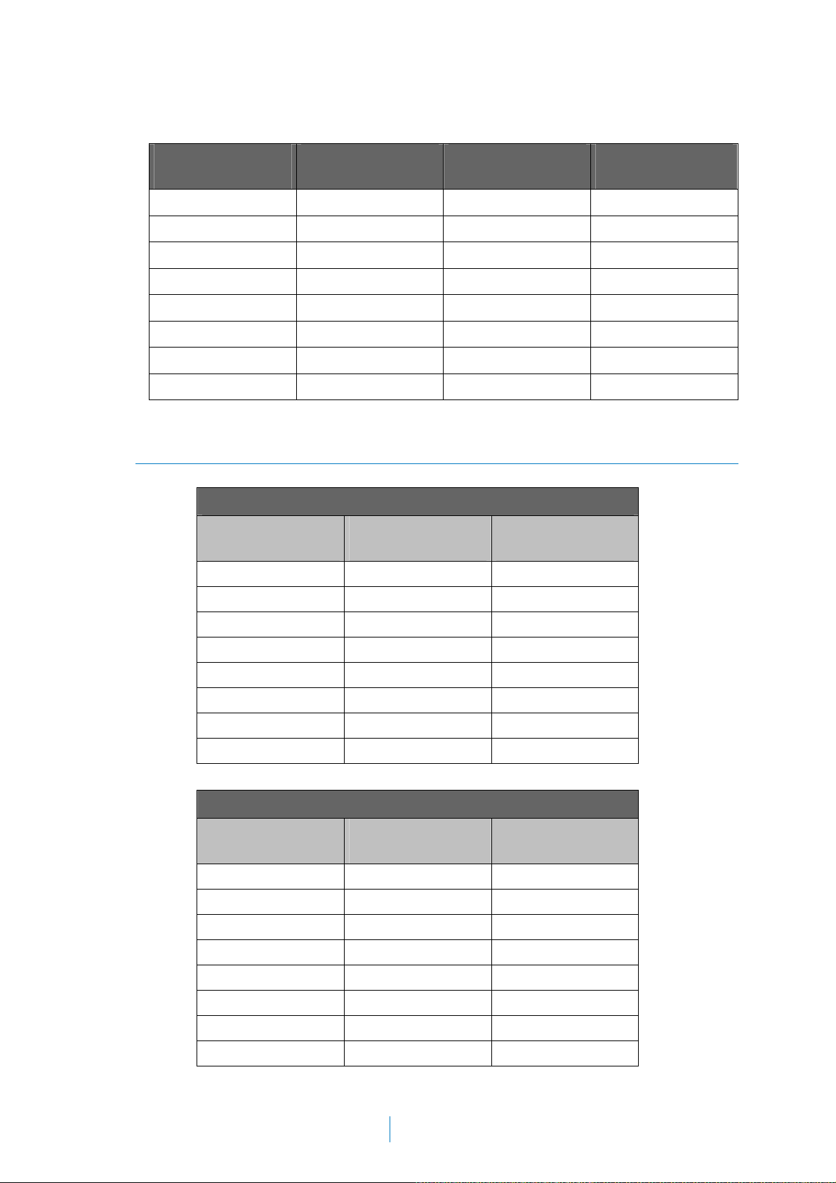
1. LINEARITY OF THE RESPONSE TO STEADY SIGNALS
f (Hz) LA (dB) t (s) E (Pa²h) Tolerance
1000 100 8 0,008889 -21% +26%
1000 110 4 0,044444 -21% +26%
1000 120 2 0,222222 -21% +26%
1000 130 1 1,111111 -21% +26%
1000 130 2 2,222222 -21% +26%
1000 140 6 66,66667 -21% +26%
1000 140 30 333,3333 -21% +26%
1000 140 144 (2m 24s) 1600,000 -21% +26%
1000 140 720 (12m) 8000,000 -21% +26%
f (Hz) LA (dB) t (s) E (Pa²h) Tolerance
63 93,8 1 0,000267 -21% +26%
63 103,8 1 0,002665 ref ref
63 113,8 1 0,026654 -21% +26%
f (Hz) LA (dB) t (s) E (Pa²h) Tolerance
8000 88,9 1 0,000086 -21% +26%
8000 98,9 1 0,000862 -21% +26%
8000 108,9 1 0,008625 ref ref
37
Page 40

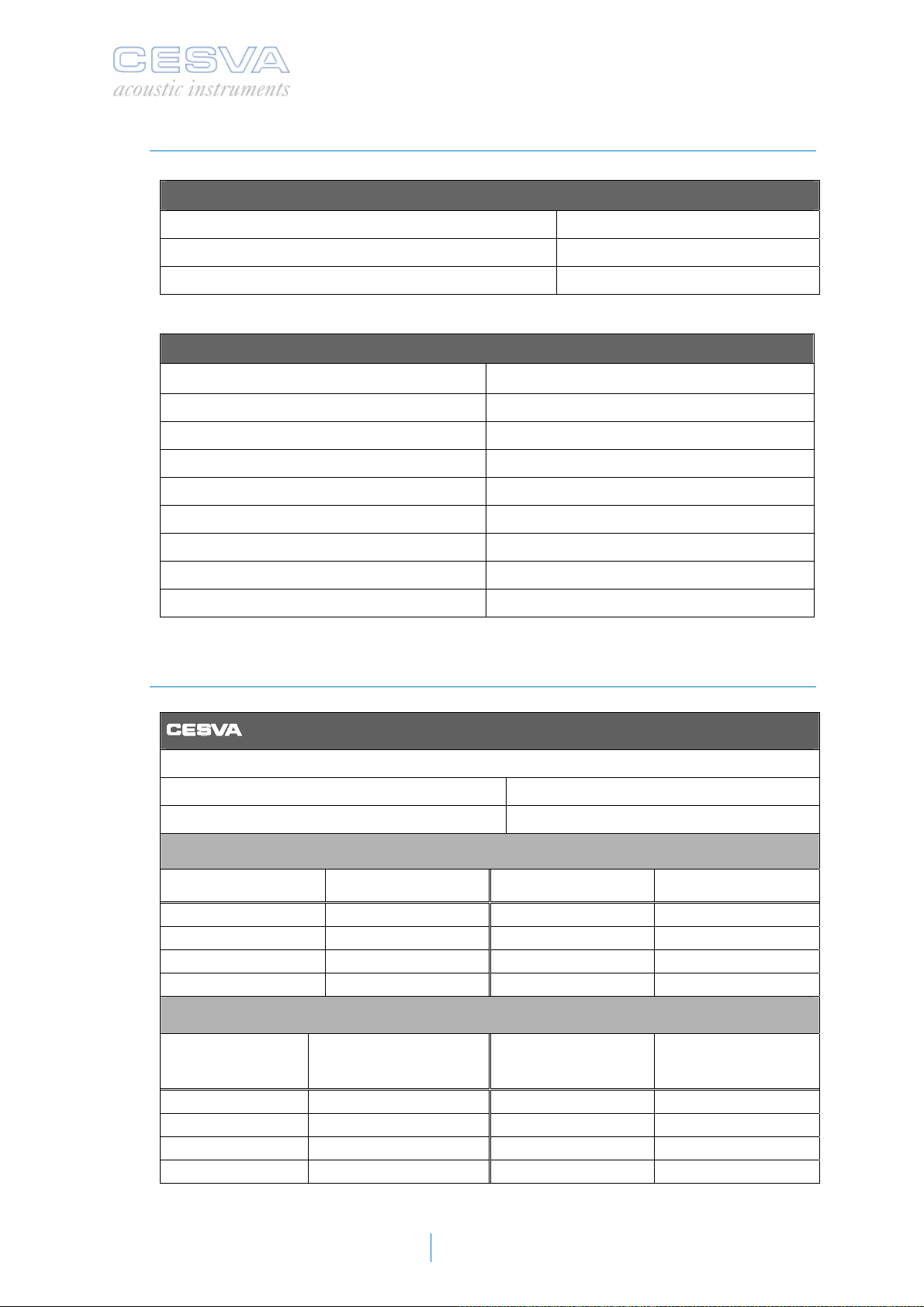
2. FREQUENCY WEIGHTING
f (Hz) L (dB)
Freq. weight. A
(dB)
t (s) E (Pa²h)
63 137,0 -26,2 1 0,013358
125 137,0 -16,1 1 0,136697
250 137,0 -8,6 1 0,768701
500 137,0 -3,2 1 2,665370
1000 137,0 0 1 5,568747
2000 137,0 1,2 1 7,341038
4000 137,0 1 1 7,010637
8000 137,0 -1,1 1 4,322724
3. RESPONSE TO SHORT DURATION SIGNALS
f (Hz)
Duration
(ms)
4000 - - 95,0 10 E4k ref ref
Burst
ratio
LA (dB) t (s) E (Pa²h) Tolerance
4000 10 1:100 115,0 10 E4k -21% +26%
4000 1 1:1000 125,0 10 E4k -21% +26%
4000 1 1:1000 130,0 10 10 x E4k -29% +41%
4000 1 1:1000 140,0 10 100 x E4k -29% +41%
4. RESPONSE TO UNIPOLAR PULSES
Polarity D (ms)
Period of
repetition (ms)
L
(dB) t (s) E (Pa²h) Tolerance
pico
+ 0,5 5 135,0 50 E+ ref ref
- 0,5 5 135,0 50 E+ -21% +26%
LATCHING OVERLOAD INDICATOR
5.
f (Hz) D (ms) LA (dB) Indicator
1000 4 140,0 no
1000 4 143,0 yes
38
Page 41

DC112d/DC112
User’s manual
8.1.2 Verification in units of equivalent sound (Leq)
A) ABSOLUTE ACOUSTICAL SENSITIVITY
a) Switch the DC112 to the menu “SENSITIVITY ADJUST”.
b) Apply a level of 94,0 dB to the microphone of the DC112 with the sound calibrator,
and wait 10 seconds.
c) Adjust the sensitivity of the meter so that the L
last calibration of the calibrator minus the free-field pressure correction of the
microphone at 1 kHz (0,1 dB), rounded to the nearest tenth of a dB resolution.
d) Select L
e) Obtain the reading in reference conditions:
and note the value measured.
A1”
LCR = L
+ Cpcl
A1”
– LC + 94dB
1kHz
indicated is equal to the level of the
AT
where:
LCR - Reading in reference conditions
L
Cpcl
L
- Measured value of L
A1”
- Free-field pressure correction at 1 kHz (0,1 dB)
1kHz
- Level of calibrator in reference environmental conditions
C
A1”
B) FREQUENCY WEIGHTING
a) Insert the microphone into the multifunction acoustic calibrator.
b) Generate a sinusoidal signal of 1 kHz with a level of 94,0 dB.
c) Select L
and note the value measured.
A1”
d) Change the frequency to 63,1 Hz, 125,9 Hz, 251,2 Hz, 501,2 Hz, 1995 Hz, 3981 Hz
and 7943 Hz. Note the values measured.
e) Obtain the free-field response: add the free-field correction to this response.
Rclf = L
+ Cclf – 84dB
A1”f
Rclf - Free -field response to frequency f
L
- Measured value of L
A1”f
- Free-field correction at frequency f
Ccl
f
at frequency f
A1”
C) LINEARITY
a) Substitute the microphone with the electrical signal adaptor and connect it to the
function generator output.
b) Select L
A1”.
c) Adjust the level of a reference sinusoidal signal of 1 kHz for an indication de 94,0 dB.
Increase the level of the signal in increments of 5 dB, up to 140,0 dB.
Return to the level of 94,0 dB and reduce the level of the signal in decrements of 5
dB, down to 50,0 dB.
Note the measured value and calculate the linearity error for each level.
EL = L
EL - Linearity error
LA1” - Measured value of LA1”
L - Theoretical level
A1”
– L
d) Repeat with a sinusoidal signal of 63 Hz. Upper limit: 114,0 dB.
e) Repeat with a sinusoidal signal of 8 kHz. Upper limit: 139,0 dB
.
39
Page 42

D) RESPONSE TO SHORT DURATION SIGNALS
a) Select L
A1”
.
b) Adjust the level of a reference 4 kHz sinusoidal signal to indicate 94,0 dB.
c) Select L
A10”
.
d) Apply a continuous sequence of 4 kHz tonebursts of 1 ms duration, with an amplitude
equal to the reference signal, and a burst ratio of 1/100. Note the value measured.
e) Calculate the difference between the measured value and the level of the reference
signal.
∆L = L
– 94dB
A10”
f) Repeat points d) - e) with a burst ratio of 1/1000.
g) Repeat points d) - f) with tonebursts of 10 ms duration.
h) Repeat points a) - g) with a reference sinusoidal signal of 4 kHz and 140,0 dB.
E) RESPONSE TO UNIPOLAR PULSES
a) Select L
A1”
.
b) Adjust the level of a reference sinusoidal signal of 1 kHz to indicate 135,0 dB.
c) Select L
A10”
.
d) Apply a sequence of positive-going, rectangular, unipolar pulses of 0,5 ms duration,
separated by 10 ms with a peak level equal to the rms level of the reference signal.
Note the value measured.
e) Repeat with negative-going pulses.
f) Calculate the difference between the indication with the positive-going pulses and the
indication with the negative-going pulses.
∆L = L
A10”p
– L
A10”n
where:
L
L
- Level measured with positive-going pulses
A10”p
- Level measured with negative-going pulses
A10”n
F) OVERLOAD INDICATOR
a) Select L
A1”
.
b) Adjust the level of a reference sinusoidal signal of 1 kHz to indicate 140,0 dB.
c) Select L
A10”
.
d) Apply a 4 ms toneburst of 1 kHz with an amplitude equal to the reference signal.
Note the overload indicator.
e) Repeat with a pulse 3 dB greater.
G) SOUND EXPOSURE
a) Select L
A1”
.
b) Adjust the level of a reference sinusoidal signal of 1 kHz to indicate 94,0 dB.
c) Select E.
Note the value of E with measurements of 1”, 10” and 1’.
d) Repeat with a reference sinusoidal signal of 120,0 dB.
e) Repeat with a reference sinusoidal signal of 140,0 dB.
40
Page 43
DC112d/DC112
User’s manual
CRITERIA FOR ACCEPTANCE AND REJECTION
A) ABSOLUTE ACOUSTIC SENSITIVITY
The reading, in reference conditions, must be 94,0 dB ± 1,0 dB.
B) FREQUENCY WEIGHTING
The indication should vary according to the following table:
FRECUENCY
(Hz)
63,10 - 26,2
125,9 - 16,1
251,2 - 8,6
501,2 - 3,2
1000 0,0
1995 + 1,2
3981 + 1,0
7943 - 1,1
C) LINEARITY
The maximum linearity error is ± 1,0 dB.
A WEIGHTING
(dB)
TOLERANCE
(dB)
± 2,0
± 1,5
± 1,5
± 1,5
± 1,5
± 2,0
± 3,0
± 5,0
D) RESPONSE TO SHORT DURATION SIGNALS
The indication should vary according to the following table:
TOLERANCE WITH
FACTOR
1/100 - 20
1/1000 - 30
∆L
(dB)
REFERENCE SIGNAL OF
94 dB
(dB)
± 1,0 ± 1,5
± 1,0 ± 1,5
E) RESPONSE TO UNIPOLAR PULSES
The difference between the indication with positive-going pulses and the indication with
negative-going pulses must be no more than ± 1,0 dB.
41
TOLERANCE WITH
REFERENCE SIGNAL OF
140 dB
(dB)
Page 44

F) OVERLOAD INDICATOR
With a pulse of 140 dB the overload indicator should not appear. It should appear with a
pulse of 143 dB.
G) SOUND EXPOSURE
The indication should vary according to the following table:
SIGNAL LEVEL
(dB)
DURATION OF
MEASUREMENT
94 1” 0,000279
94 10” 0,002791
94 1’ 0,016746
120 1” 0,111111
120 10” 1,111111
120 1’ 6,666667
140 1” 11,11111
140 10” 111,1111
140 1’ 666,6667
EXPECTED SOUND
EXPOSURE
(Pa2h)
TOLERANCE
(%)
- 21; +26
- 21; +26
- 21; +26
- 21; +26
- 21; +26
- 21; +26
- 21; +26
- 21; +26
- 21; +26
42
Page 45

DC112d/DC112
User’s manual
8.2 Alternative free-field method
For alternative free-field verification, suggests the use of the B&K 4226 multifrequency calibrator, using the following procedure:
a) Switch on the multifunction acoustic calibrator and select:
Function
Sound field
Sound Level dB
Æ Calibration
Æ Pressure
Æ Lin. 94
b) Insert the microphone of the DC112 into the acoustic coupler of the multi-function
acoustic calibrator
c) On the multi-function acoustic calibrator select:
Frequency Hz
Æ 63
Wait until the corresponding LED stops flashing.
Note the measured value of function L
A1”
.
d) Repeat with the frequencies 125, 250, 500, 1k, 2k, 4k and 8k.
e) Remove the microphone from the acoustic coupler and repeat points
b) to d).
f) Calculate la arithmetic mean of the two values measured at each frequency.
g) With the values from point
= Lmf – Lcf + Cpclf – Lm
Lclr
f
f), calculate the free-field response relative to 1 kHz.
1kHz
+ Lc
1kHz
– Cpcl
1kHz
where:
- Free-field response, at frequency f, relative to 1 kHz
Lclr
f
- Arithmetic mean of the measured values at frequency f
Lm
f
- Level of calibrator at frequency f
Lc
f
Cpcl
- Correction of sound field generated by B&K multi-function
f
acoustic calibrator model 4226 in free-field at frequency f
Lm
Lc
Cpcl
- Arithmetic mean of the values measured at 1 kHz
1kHz
- Level of calibrator at 1 kHz
1kHz
- Correction of sound field generated by B&K multi-function
1kHz
acoustic calibrator model 4226 in free-field at 1 kHz
43
Page 46

44
Page 47

Page 48

Villar, 20, bajos – 08041 BARCELONA (ESPAÑA)
Tel. (+34) 934 335 240 – FAX (+34) 933 479 310
e-mail: info@cesva.com
www.cesva.com
 Loading...