

Cessna USAF Series, T-41C 1990, T-41D 1991, T-41C 1991, T-41D 1990 Flight Manual

T.O.
1T-41C-1
FLIGHT
USAF
T-41
CID
MANUAL
SERIES
AIRCRAFT
AND
BASIC
DISTRIBUTION
OoO
US.
requests
Other
WARNING
f*port
Arrn.
1SiZg,
o{
Act
are
laws
HANDUNG
statement
reconslruction
COMMANDERS
AiR FORCE
13 Hav
CHANGES
ALL
STATEMEhIT
contraclors
shall
-
This
Control
amended
as
subiect
to
ANDjE_STRUqTION
destroy
ind
ol the
TO
PUBLISHED
91
/
HAVE
only,
ref erred
be
document
(Title 22,
Act
(Title
severe
by
document.
ARE
THE ATTENTION
UNDER
865
F34601-90-D-031
MERGED
BEEN
-
Distribution
Administrative
OC-ALC/TISDT,
to
contains
U.S.C., Sec.2751
50, U.S.C.,
criminal
any
penalties.
NOIICE
method
RESPONSIBLE
OF ALL
AUTI-IORITY
1
MAKE
TO
authorized
and Operational
Tinker
technical
that will
OF THE
data whose
2401
App.
-
Handle
FOR
AFFECTED
SECRETARY
.1
5
et seo.)or
prevent
BRINGING
CHANGE
COMPLETE
A
THIS
lhe Department
to
15
Use,
OK 73145-5990.
AFB,
export is restricled
the Exporl Adminislration
et r€q.).Violalions
compliance
in
disclosure
THIS PUBLICATION
PERSONNEL.
OF THE
AIR
PUBLICATION'
of Delense
Seplember
ol lhese exporl
wilh lhe distribulion
and
199o.
by lhe
ol the contenls or
FORCE
SEPTEMBER
1
15 APRIL
1990
1991

TO" 1T-41C-1
LIST
,
EFFECTIVE
OF
-
Dates
ol issue
Original
Change
TOTAL NUMBER
Page
No.
for original and
...0 ..15 Sep90
...1 ...15Apr91
.
PAGES
OF
*Change
PAGES
-
IN THIS PUBLICATION IS
No.
INSERT
INOTE: Theportionofthetextaffectedbythechangesisindicatedby
changed
pages
Page
No.
LATEST CHANGED PAGES.
a vertical line in
illustrations
Changes to wiring
are:
the outer
are indicaled by
diagrams
CONSISTING
90
*Change
No.
DESTROY
margins of
Page
No.
SUPERSEDED
miniaiure pointing
are indicated
THE
OF
page.
the
FOLLOWING:
Changes
by shaded
.Change
PAGES
to
hands.
areas.
No.
A
Change
in
'Zero
1
this
column
indicates
an original
page.

T"O.
1T-41C-1
Tech
Co
nf ig
n ical
ratio n
u
Orde r
Status Record
lEq
ipment
u
cl(Cl
Blank)

T.O.
I
1T-41C-1
Flight
and
This page
Manual
Manuals,
you
Ollicer
Manual,
Operational
published
is
Change
Flight Crew
are missing
and
or revision.
any
get
your
Checklist,
publications
copy. Changes in
FLIGHTMANUAL
T.O.
1T-41C-1
FLIGHT
T.O.
CREW
CHECKLIST
1T-41C-1CL-1
Saf ety
Supplement,
Supplement
with
each Safety and Operational
provides
lt
Salety Supplements,
listed
-
a comprehensive
on this
preparation
T
page,
are
Status
Supplement,
listing
and Operalional
your
see
shown
DATE
1Aug90
DATE
1 Aug
ol the
Publications
parentheses
in
I
90
and
each Flight
current Flight
Supplements.
Distribution
(
).
lf
TCHANGET
-
1
15Apr91
CHANGET
-
1
15 Apr
91
Change t i

T.O. 1T-41C-1
Flight Manual,
Saf ety
and Operational
CUNREruT
Number
SUPPLEMENIS
Date Short Title
Supplement,
Supplement
Status
Flight
Pages
Manual
Affected
REP
Number Date Disposition
LAC
E D/RESCIN
D
ED S U
P
LEM
P
E/VIS
-
ii

T.O.
1T-41C-1
SECTION
I
ll
lll
IV
V
VI
vil
TABLE
OF
Description
Normal
Procgdures
Emergency
Crew
Opgrating
Flight
All
Duties
Limitations
Characteristics
Wgathgr
CONTENTS
TITLE
and
Procedures
(Not
Operation
Operation
! .'
.,
Applieable)
...,,,..
r r r r r r
r
',
r r . r
r r
.. !...
.,,,,,,,,,,
r
r,,,.
',
. r..
r' r,,
r..
PAGE
'
r
r
-
'...4-1
. .5-1
r...6--l
-
-,7'1
'1-1
-2-1
'3-'l
GLOSSARY
APPENDIX-
Alphabgtical
r r.
r
rr
r r..
r r
Performancg
r.,
i.
INDEX
,
rrr.
r r
r.
Data
r,.
r
r.,,
'
r r.,,,,,.,...|NDEX-1
'.
..
r
'
'r
'
r. r
rrr
rr
r'|
r..G-1
'|
'!
r
'A-1
ill

T.O"
1T-41
C-1
Figure
1-1
1-2
1-3
1-4
1-5
1-6
1-7
1-B
1-9
1-'t0
1-11
2-1
z-z
2-3
3-1
3-2
5-1
co
J'L
5-3
5-4
5-5
5-6
5-7
6-1
6-2
A1-1
A1-2
A1-3
A1-4
A1-5
A1-6
A1-7
A1-8
41-9
A1-10
A1-1
A1-12
A1-13
A1-14
A1-15
A1-16
A1-17
A1-18
LIST OF
LLUSTRAT
Title
I
The T-41 C
Prinicpal
Lelt Lower
Right
Cockpit
Oil System
Syslem Schemalic
Fuel
FuelQuanlity
Electrical Syslem
VHF Radio
VOR Receiver . .
Transponder
Exterior
Wind Direction
Maximum Glide .
Typical Forced
Airspeed
Aircraft
Dimensions
Switch
Lower Switch
Forward
lnspection
Limitations Gauge
View .
Schematic
Dala
Schematic
. .
Landing
Panel
Panel
(U.S.
Gallons) . . .
Pattern
ONS
Page
ix
1-2
1-3
1_3
1-4
1-8
"l
-o
1-1
1-12
1-18
1-18
-19
1
1-J
2-7
2-11Tralfic Patlern
3-4
3-7
5-1
1
OilTemperaturecauge... 5-2
Pressure Gauge
Oil
Tachomeler
Flow lndicator
Fuel
Fuel Quantitylndicator....
Suction
Stalling
Stalling
Airspeed
Airspeed Correction
T-41C
Weight and
Center
Loading Graph
Takeof
Airspeed correction
I and
Take-Olf
Maximum Rate-of-Climb
....
Gauge
Speeds
Speeds
Conversion
of
Gravity
(2200
(2500
Balance Chart
Moment
Landing Crosswind
Data
Pounds Gross
Pounds
Gross
Chart
Table
Chart
Envelope
Data
Weight
Weight)
Chart
OplimumCruisePerformance....
'1
Cruise
Landing
Take-Off
Maximum
Cruise
Cruise
Cruise
Cruise
Range
&
Distance
Dala,
Performance
Perlormance
Performance
Perlormance
Perlormance
Data .
T-41D Model
Rate-ol-Climb
(2500
(5000
(7500
(10,000 feet) .
Data
T-41D Model
Data,
feet)
f eet)
leet)
5-2
5-2
5-3
5-3
5-3
6-1
6-1
A-2
A-3
A-3
A-4
A-5
A-5
4-6
A-7
A-7
A-7
A-B
A-B
A-9
A-9
A-10
A-11
A-12
A-13
iv

T.O.
1T-41C-I
l
Cod
ing
and Se
lndicales
AIRQRAFT
information
CODTNG
rializatio
that applies
"D"
MODEL
to
"D"
n
modified
airplanes,
69-7755
69-7756
i
All
other
airplanris are standard
l
l
1
1
I
"C"
models,
I
t
I
I
I
t,
i
1
I
I
I
,
I
I
t'
I
I
I
I
i
I

T.O, 1T-41C-1
IMPORTANT!
FLIGHT
Looseleal
use
purchase procedures
Schedule
with
items. Due
ers be used
MANUAL
with
your
binders
your
(FSC
supply
to the size of
BINDERS.
and sectionalized
manual. They
and are
Group 75, Ollice
personnellor
section I it is
al the beginning
are obtained
listed in the Federal
assistance in
ol each system
Read these
scoPE.
manual
The inlormation
plane,
its characteristics,
dures. Your
avoided. This
circumslances,
sound
circumslances
tabs are
Supplies,
suggesied thal
judgemenl.
adverse w€ather,
procedure(s)
available
through
Part 1).
procuring
description.
in lhe
experience
llying
manual
but ars a
lerrain,
may require
presenled
lor
local
Supply
Check
these
divid-
provide-s
Multiple
pages
provides
specific normal
and
is recognized;
lhe
poor
subslitule
emergencies,
or extenuating
modilication
this manual.
in
carefully
you
possible operating instruclion
best
lor
of the
general
a
with
emergency operaling
and
lherelore,
basic flight
3
I
./j
knowledge of lhe
procs-
principles
under mosl
/.\
air-
are
PERMISSIBLE OPERATIONS.
takes
only what
which
prohibited,
by HQ USAF
constantly
T.O. 0-1-1-3
stales
must
or
Manual
are
remain
supplement
checklists
The Flight
mally
conliguralions
lhis manual
unless authorized
HOW TO BE ASSURED
You
ol
supplements.
manual
manuals,
"positive approach"
a
you
can do.
excesd the
except
OF HAVING LATEST
aware
stalus
and supplements.
Usually operalions
limitations
actual emergencies,
in
ACADEMY/CWO.
of the latest manual,
(supplemenled
provide
page
and
as
specif
DATA.
monthly)
a listing
nor-
or
ied in
. .
checklists
and lhe
ol lhe
lalest
current
ARRANGEMENT.
This
simplily
manual.
subsections,
systems.
struclions
characlerislics
lions ll,
dures
tion Vlll.
and stalus
llight
llight
manual
reading
For
You
in section
and
lll,
in seclions
divided into
is
straight
it
convenience,
describing
be lamiliar
must
the limitations
l,
in section
lV. ln adverse
ll and lll
t)
(.,r[
t-J
'
Yr,
seven interdependent
through or using
section I has
syslems
maior
with the systsm operating
perform
Vl, to
weather conditions, the
shall be
\f4
re:
been divided into 20
or
in
section
the
modilied
sections to
it as a relersnce
groups
ol relaled
V and the llight
procedures
proce-
as
shown in sec-
sec-
in-
vi

CHECKLISTS.
T.O. 1T41C-1
The Flighl
been issued as s€parate
current applicable checklists.
lor
are arranged
Manualcontains
in
same
lhe
lhe
amplilied
technical
order.
lf aulhorized
orders.
Line
Supplement that aflects a checklist,
lected
page,
old
the
checklist
lile the
page (in
page.
page
case lhe
HOW
Each llight crew
Manual,
Checklists.
need lhem to
Manuals
Basically,
lion Requirements
and
00-5-2
publications.
these
SAFETY
Safety supplements
about hazardous
conlain
salely
of
lransmitting
issued by leletype (interim)
supplements
a new
supplemenls
around
printed
ll a
in f;ont
supplement
ol the exisling
supplement
TO GET PEBSONAL
member
Salety
personnel -
publicalions
AND OPEBATIONAL
operating
modilications.
Supplemenls,
The required quantilies
assure
you
give
Make sure
their
it is their
must order
Table
detailed
lo the
are a
condilions
inslructions,
Operational
inlormation
are eilher
number) or by a quick
are
identilied
the borders
of the
checklists.
see the
items in lhe
write
checklist page,
is
cancelled).
COPIES.
is entitled
prompt
job
the required
(T.O.
inlormation
asystem
llight crews
rapid
or saf ety
not
or as
replaced
by red
pages.
Abbreviated
latest supplemenl
Flight Manual
by
an
interim
in the applicable
contains
lo
Salety or
a replacemenl
personalcopies
Operational
to
should
receipl.
tulf ill
your
be
Check
Technical
quantities
0-1-1-3).
is established
TechnicalOrders
properly
lor
at
immediately
SUPPLEMENTS.
means ol
lransmitting
problems.
or restrictions
supplements
involving
printed
by
change
letters "SS"or
{formal)
a lormal
salety.
printed
to lhe
checklists
slalus
and
checklists
operational
change on
checklisl
but do
not lhrow
of
th€
Supplements,
ordered
with
Order
on
belore
your
the
requests.
publica-
ordering
your
base
to deliver
upon
receipt.
inlormation
These
supplements
that affect
are
safely
a rapid
Supplements
supplements.
supplement (wilh
manual.
by
black
letters',OS"
have
page
the af-
out
Flight
and
you
Flight
O0-5-1
these
or
m€ans
are
lnterim
Formal
All supplements
has the letters
the letter
plied
each
i and ii)
These
information checkthe
and the
on supplements.
lalest on top,
or safety
"S'in
with.
printed
to show the
pages
title
supplemenl.
ars
'SS
the number.
A safety
supplemenl
are
only currenl
blockof
File supplements
regardless
numbered
lhe
'in
and operational
current
index,
each
supplement
ol
in sequence.
number.
All currenl
and each
slatus
when
T.O. o-'l
whether
salety
A
An operalional
supplements
supplemenl
change
of suppiements
prepared.
-1
show
in lront
il
-3.
is an
The
the
operational
to lhis manual
To be
page
title
ect
eff
of the
supplement
supplement
must
be com-
page
status
and
checklists.
sure ol lhe
of
lhis
of each
manual,
with the
supplement
has
is
(pages
latest
manual
change
in
vii

T.O_ 1T-41
C-1
CHANGE SYMBOL
The following def
t\/AEINING
initions apply to the
The
lhis
Changes
WARNINGS,
The
found through
Operaling
injury
Operating
equipmenl
to
operaling
An
to emphasize.
tial
"shall,"
words
change
symbol,
paragraph,
to illustrations are
CAUTIONS, AND NOTES.
following
or loss
de{initions
the
procedures,
ol
procedures,
il
procedure,lechnique,
"will," "should,"
as illustrated by
indicates texl changes
indicated
apply to
manual.
"Warnings,"
WARNING
techniques, etc.,
lile if not caref ully
lollowed.
ii:r'.::3
lechniques, etc.,
not caref ully lollowed.
NOTE
etc., which
"may':
and
lhe black
made to
with
a miniature
"Cautions,"
which
which
line
in the
lhe current
hand.
can
resull in
can
result
is
considered
margin of
revision.
"Notes"
and
personal
in damage
essen-
and
express
847
to
express
and shall be
shallbe
possibilily
personnel
of the latest data
this manual
should be
Oklahoma
Used to
Used to express a non-mandatory
complishment
Used lo express an acceptable
ment
to
YOUR RESPONSIBILITY
ellort is made to keep the
Every
with operating
assure inclusion
an error
unless we know
tions regarding
welcomed. These
AF Form
5990.
SHALL or WILL
lhat the requiremenls
SHOULD
desire
construed as
MAY
or suggested
conslrued as a
non-mandatory
("might').
_
TO
LET US KNOW.
Flight Manual
and
a constant review
in
the manual.
of its existence.
or any
lorwarded
City ALC/TISDTM Tinker
phase
Comments,
of lhe
through
are binding
or
a non-mandatory
currenl.
of accident
However,
and
prelerred
means
provision.
Reviewconlerences
and
we
correclions
Flight
Manual
your
major
AFB,
Oklahoma
mandatory.
method
provision.
ol
accomplish-
Not
llight
cannot
and
program
command
of ac-
used
reports
correct
ques-
are
on
73145-
vilt

T.O.
1T-41C-l
r-
l
'1
".''lj;i';;ifilsffiffiilllrrrl
rc6
41c
rmrrl
IilIX
"ffiffi$g'H!llli
ffiffiffiffiH#FffiilFTII
-ffiffi
,ffiffillHll
ryffirrtrrr-t
Ilrrtrrrnrrli
rrrrrrrrn.fri
1
Figure
1 . The
T-41C
Aircraft
ix/(x
Blank)
T.O. 1T-41C-1
SECTION
Aircrafl
The
Engine
lnject
Fuel
Propeller
Engine lnstrumenls
Oilsystem
Fuel
System
Electrical
Nosewheel
Brake System
Wing Flap
Flighl
ControlSystem
Stall Warning Horn
lnstruments
Commun
Lighting
Cabin Heating
Cabin Doors
Seal Operation
Bells
Seat
I
ion/Air
System
Steering
System
ications/Navigalion
and
and Shoulder Harnesses
lnduction
System
Ventilation
System
Equipmenl
System
Table
DESCRIPTION
of Contents
AND
OPERATION
1-1
1-1
1-2
1-5
1-6
1-7
1-7
1-10
1-13
1-13
1-13
1-14
1-14
1-14
1-16
1-17
1-19
1-20
1-24
1-20
THE
AIRCRAFT
The T-41C,
Aircrafl Company, is
strul-balanced,
guishable
engine
lixed
and
metal, fixed
all
Aircralt
side-by-side
sion
lo
T-41D has
The T-41D has a variable
improves
designed
leatures
placed
lorward on
tricycle
pitch,
generally
are
seals
lour-place
the
performance.
and manufactured
all melal,
an
high wing
of
landing
with
seating.
same
aircraft
the
lhe
gear.
and designed for
conligured
lhe capability
On T-41D
characterislics as T-41C.
pitch propeller
single-engine,
monoplane.
are
fuselage centerline
propeller
The
best climb.
with
two
of
aircrafl, lhe
Dimensions
The overall
lows:
WingSpan
dimensions
(Figure
1-1)
ol the
aircralt are as
......36'2"
Height .8'9112"
Length . . .25'11"
Wheel
Base ......7'2"
Propeller . . .6'6"
Cessna
by
Dislin-
its single
lorward
conver-
which
fol-
Gross
This aircralt is FAA-certified
and
are as
is
Reler
tional
Weight
utilily
categories.
lollows:
Normal
Utility
[lNormal
lluritiry
Seclion V, Weight
to
inlormation.
in
Maximum
......2,500
Limitations,
both
the
gross
weights
.2,200 lbs
...2,550tbs
.....2,250
for
normal
lbs
tbs
addi-
ENGINE
The
aircraft
fuel-injected,
360-D engine,
inlernal
an
propeller
in
air
and air
trolled by the ignition
air
spheric
and lhe
in
the six cylinders. Spark
is
ignited
cockpit.
the
powered
is
six-cylinder
rated
at
combustion
is derived lrom
provided
in ihe cylinders
pressure
posilion
by
(see
of
the throttle
horizontally-opposed,
by a
Continental Model
210
bhp
engine,
2,800 RPM.
at
power
lhe ignition
to
two magnetos
switch.
The
ratio
is determined
engine-driven
and mixture knobs
to
ol
ignite
and is
ol
luel
l0As
turn the
luel
and
lhe luel
con-
luel
and
by atmo-
pump)
Change
1
1-1

T"O. 1T-41C-1
lgnition
Anytime the engine is
by two
its
to
los are engine-driven
are independent
and ol each
as oullined
lgnition
The
panel,
The swilch is labeled
in
a
are for
gency purposes
switch determines which
are operating.
System
lurning,
magnetos. Each
associated set ol
and
ol
the aircralt electrical system
other. Magnelo
in
Section ll, Belore Takeoll
Switch
ignition
clockwise direction. The
swilch, located
conlrols
checking
ignition
the
OFF, R,
magneto
the
only. The
ignition
magneto
spark
plugs.
self-contained.
operation
on the
system
L,
R
system
position
portions
is
supplies
The
is
lelt
lower switch
(figure
BOTH,
L
and
ol
the
of
the system
supplied
power
magne-
They
checked
Check.
1-2).
START,
positions
or emer-
ignition
Starting System
Electrical
supplied by the aircrafl ballery
power
to the spring-loaded
master switch ON)
allowing
cranking the engine.
automalically
Mixture
power
source.
lor
When
energizing
the ignition switch is
START
slarter
the
voltage
relurns
Release
lires.
propeller
starter molor more lhan
onds
start
cranking, allow a 3 minute
belore
the starter
Never engage
is
al one time.
within
reengaging
llow
to
lo the
As
lhe switch is released, it
to lhe
soon
as
lhe starter
turning.
Do
ll
lhe engine fails
30 seconds
the slarter.
BOTH
a tolalol30
Control
the starter may
position
nol operate
ol cumulative
cooling
or an external
turned
(with
solenoid closes
starter
position.
as the engine
while
molor,
the
lhe
sec-
to
period
be
the
PRINCIPAL
DIMENSIONS-
Figure 1-1. Principal
rMrxlmum
norr
wlh
Dimensions
h.lghl ol ri.plmr
g.rl
dlpr.trad.
The
mixlure control
throttle
push
silver
control knob lorward
is
accomplished
toward lull
lean. ll large or rapid
press
position
the
is identilied
and
button
rich or
lock bution on
controllorward
the
knob
is
to the right
by a red knob with
lock in
or alt
by rotating
counlerclockwise
changes are required,
cenler.
the
to adjust the mixlure
the
the conlrol knob
or alt as
knob
required.
Moving
clockwise
toward lull
Throttle
Engine
is identilied by its smoolh, round while
throttle
in
the alt
FUEL INJECTION/AIR INDUCTION
TEM
Fuel and air arrive
tion
air
the
pump.
mixture with
also
mixture conlrol knob.
power
is
lorward
lhe
position
separately, via
induction
aneroid in
The
is conlrolled
operated in the
position
it is
manilold. Fuel flow is
the engine-driven rotary vane
aneroid automatically
altitude changes. The
meters luel based
by
the throttle
convenlional manner
the lhrottle is open,
closed.
at the
the
cylinders
luel injection
the
position
on
knob.
lor
syslem
metered
changes
mixlure
ol the
a
the
de-
and
which
The
-
and in
SYS.
combus-
and
by
luel
lhe
unit
ol the
1-2

T.O. 1T-41 C-1
FUEL STRAINIER
1.
2. MASTER SWITCH
AUXILIARY
3.
4. STROBE
PITOT HEAT
5.
NAVIGATION
6.
7. LANDING/TAXI
FUEL
LIGHT
SWITCH
LIGHT
LIGHT
KNOB
PUMP SWITCH
SWITCH
SWITCH
SWITCH
Figure
B, MANUAL
IGNITION
9.
10. FUEL
11. PARKING
12. FLAP
13.
CIRCUIT
1-2. Lelt Lower Switch Panel
PRIMER
SWITCH
SHUTOFF
BRAKE
CIRCUIT
BREAKERS
KNOB
KNOB
BREAKER
1.
THROTTLE
2.
FUEL
CABIN
3.
MIXTURE
KNOB
AIR
KNOB
Figure
Right Lower
1-3.
4.
FLAP SWITCH
5. CABIN HEAT
Switch
Panel
KNOB
1-3

T.O. 1T-41C-1
1.
MrKE BUTTON
2.
CLOCK
ALTIMETER
3.
4.
AIRSPEED INDICATOR
TURN
5.
DIRECTIONAL
6.
7.
VERTICAL VELOCITY
& BANK
INDICATOR
(ON
YOr(E)
INDICATOR
INDICATOF
8. ATTITUDE INDICATOR
(NAV)
voR
e.
8@
10.
TRAhISPONDER
MAGNETIC COMPASS
11.
FREQUENCY PLACARD
12.
CARBON MONOXIDE
13.
DETECTOR
RADIO
14.
FLAP INDICATOR
15.
FUEL FLOW INDICATOR
16.
FUEL OUANTITY
17.
INDICATOR
18. TACHOMETER
19.
AMMETEB
20.
SUCTION
2'1.
OIL TEMPERATURE
INDICATOR
22.
OIL PRESSURE
INDICATOR
23. AUXILIARY
24.
TRIM
GAUGE
MIKE
TAB
JACK
1-4
Figure
1-4. Cockpit
Forward
View

From
lhe mixlure
air
conlrol unit. Air
lrom
the
becomes
a
spring-loaded
lrom
the engine
The
lhrotlle
air
valves
the
correcl ralio
into
air
distributor,
lhrough
induction
litl-er.
air
clogged,
simultaneously
in lhe fuel-air
the air induction
luel is
the luel injection
manifold
the intake valves.
intake valves
cylinders. Drain
of
lhe intake
accumulale
are installed
ports
during
Propeller
fn"
[l
two-bladed,
propeller.
means
chanically
governor
lhe
maintained,
of
governing
peller
the blades
pressure
centrilugal
twisls
The
the blade
lor mosl
lakeofl, when
quired,
propeller
keeps
respecl
allows lhe
air
gine
mum
time.
for,
is
small,
many,
the low
aircralt
conslanl-speed,
Propeller
propeller
of
a
linked
on
the engine. A
governor
engine
hub.
establishes
and the
oil, boosted
pump,
Oilpressure
toward high
lrom
lhe
lorce,
the blades
constant-speed
angle
conditions
adjusted
maximum
the conslant-speed
blade
angle
the
angle
to the
per
revolulion.
turn
lo
amount of tuel
The
although
the
airplane
relative wind.
propeller
at high RPM
high
RPM
the mass
number
the
slipstream velocily
speed, tlre
unil luel llows
enters
the f uel-air
lo the
Alternalively, if
suclion from the
permitting
door,
compartment
air to be drawn
inlo the
controls
control unit
of luel
lo the fuel
manifold.
evenly distributed
nozzles. Air lrom
enlers
Fuel injection
lines
lo drain
engine
is
equipped wirh
operation
lhe cylinders
nozzles
on
the lop side of
are inslalled
any
shutdown
governor
is
luel which
controllable
control knob which is
to the engine-driven
setting inlroduced
the engine
governor
to high
lrom
to or
acting
pitch
governor
assisted
loward low
propeller
encountered in
power
pitch.
or
ol attack
handle
to
This light
and
into heat
also
creales
of
air
then controls
pressure
piston
the
on the
(low
RPM). When
piston
to
the
by
lor
small and eflicient
internal
an
pitch
(high
automatically
maximum
and
propeller
The
low
At
lhe same
a smaller mass
load
allows
to convert
energy
maximum
handled
ol revolutions
is
high,
lhrust is maximum.
fuel
and
control unit
the air
engine opens
the
distributor and
At
the cylinders
lo
on
lhe boilom
or
an
speed to
lilter
system.
luel
and
delivering
fuel
the
the
lhrough
and the
the
may
priming.
ail metat,
regulated
me-
propeller
inlo
be
llow
by
by the
in
piston
is
pro-
the
lwists
oil
relieved,
spring,
RPM).
keeps
efficiency
llight. During
thrusl are
is
blade
re-
at a low
angle
with
lime,
ol
lhe en-
the maxi-
given
in
a
thrust;
per
revolulion
per
minule
and wilh
is
T.O.
1T-41C-1
After
lift-ofl,
lhe conslant-speed
to a higher
blade
elficient
higher
handled per
gine
RPM,
wear,
After
reduces
power
and
then
RPM.
Al
cruising
llight
and less power
lakeofl
power
increasing
Again,
the reduced
of
air handled per
than
ollsel
and
an increase
is
still
increased
The T-41C
one
main
lhe
setting
amount
[lUanitotd
On
the
speed
the
throttle
controls
rectly
propeller
The
propeller
indicated
it
(manifold
ol
the
lhrough
This
increase
increases
RPM
remains
throttle
pitch
lhe
matically
pitch
decreases
that
the
as
lhe speed
angle
angle
and
the
by reducing
keeps
wilh
blade
reducing
keeps
takeolt
power
the
by lirst
increasing
altilude,
or
climb,
lhe
provides
this
engine
by
small
wilh
respect
angle
revolution.
decreasing
blade
a
because
an
with
power
ot
the
power
of
pressure
other
hand,
propeller
and
the
the
engine's power
indicated
control
blades
on
lhe
lachometer.
pressure)
propeller
the
seiling
RPM
blades
action
in
the
air load
constanl.
(manilold
angle
decreased.
remains
propeller
(or
the
to
increases
luel
lhrust
climb
output
the
when
is
pilot
lhe
the
manifold pressure
angle
a
lorque
power;
revotulion
decrease
in
airspeed.
the
increase
its
lixed-pitch
control
throtile
and
the
the
has
lwo
propeller
on
lhe
manilold pressure
changes
governs
and
is increased,
is
of
the
propeller
on
of
the
This
the
air
constant.
ol
the
airplane
automalically
pitch).
angle
Again,
of
attack
the relative
lhe
This
decreases
consumption
at
a maximum.
is
established
of
the
engine
lhe manilold
blade
required
-
the
propeller
T-41D
propeller
the
pressure)
propeiler
load
angle
lhe
airplane
than
again
blade
reduces
lo
decrease
requirement
lor
although
greater,
is
in
slipstream
The
angle
in
airspeed.
propeller
throttle.
wilt
control
or
&
Engine
with
power
main
conlrol.
output
the
the
As
lhe
lhe
automalically
goveinor
pitch
proportionalely
propeilei
Conversely,
blades
decrease
on
lhe
increases,
the
wind.
mass
and
lo
is
is
angle
has
ln
lhat
engine
RpM
its
constant_
controls
The
which
pitch
RpM
throille
pitch
increased
so that
when
ii
decreased,
in
propelier
changes
higher
small
and
The
ol
the
en_
engine
pilot
the
to
climb
pressure
lower
lhe
in level
used
engine
and
lhen
the
RpM.
lo malch
the mass
it
is
more
velocity
ol
attaci<
been
has
onty
case,
both
the
BpM.
throlile
is
indi_
gauge.
ot
ine
which
sefling
angli
syslem.
the
lhe
is
auto-
propeller
so
air
in
-
is
1-5

T_O.
1T-41C-1
For
lhat
amount
RPM,
engine
stress
undue
nenls
ure.
ln
overstress
awareness
cially
pressure).
throttle
When
be
changed
avoid
lhe
decreased,
given
any
should
of manilold
the maximum
cylinders
on
lhem. lf
slress
and
eventually
order
to avoid
when
the
increasing
The
selting (mani{old
Except
CREASE
go-arounds,
sure
proper
during
to exceed
both
manifold pressure
signif icantly,
overstress
order.
reduce
When power
verse
the order
pre
ssu re.
lf
RPM
is
sure, manilold
increase
manufacturer's
RPM,
nol
lhere
be
exceeded.
pressure
allowable
could
be exceeded, placing
repealed
could weaken
cause
conditions
cylinders
ol
the
tachomeler
lhe
combination
WARNING
fuil
throtile/prop
operations
never
engine
by
making
When poweF
manifold pressure
settings
-
increase
reduced
and
are
cAuiloN
before
pressure
possibly
lolerances.
is
manifold pressure
a
lf
an
is
carried
pressure
too frequenily,
the
cylinder
engine
structural f
that would
there
must
be a constant
indication,
throtile
setting
to avoid
pressure)
such
allow
RpM.
pilot
lhe
power
being increased,
RpM
will
and low
FULL
as takeolfs
manifold pres-
and RpM
can
adjustments
settings
be{ore
f irsl,
then manifold
manifold
aulomalically
exceed
excessive
lor
a
within
compo-
possibly
(manilold
is
a
lN-
and
need
further
are
pres-
the
given
the
undue
lhis
ail-
espe-
high
RpM.
to
help
in
being
RpM.
re-
Fuel
Flow
Fuel
llow
is indicaled
indicating
lhe
gauge,
Bg lorl
!31.
settings,
mixture
ll
luel
panet.
calibrated
Fuel.f
but
conlrol
the luel
lumes
inslrument
lt is
of tuet
low
Cylinder
The
cylinder
the
right
number
Fa.hrenheit.
cal-resistance
power
ils
head
side
3 cylinder
The gauge
f rom
[leropetter
Control
eralion
throtlle.
decreases
RPM
gressively
and
knob
plished
RPM
large.or
lock
control
Tachometer
of
engine
ol
lhe
Ptacing
lhe
setting.
increases
decreases
forward
by rotaling
or
counler-clockwise
rapid
butlon
on
lorward
lndicator
located
a direct
to indicate
being
wiil
vary
cruise
luel
knob.
WABNING
gauge
llow
may
enler
Head
of
type
lhe
Controt
propeller
the knob
blade
Moving
engine
or
changes
lhe
or
Temperature
temperalure
the
instrumeni
head
lemperature
aircrafl
RpM
angle
the
the
aft
to
the
knob
control
aft
as required.
by
llie
right
on
reading
approximate
metered
wilh
throtile
llow
can
malfunctions,
the
cockpit.
gauge
temperaiure
is
conlrolled
bulb
electrical
Knob
is
accomplished
conlrol
in
and
RpM.
adjust
are
knob
lhe
fullforward
provides
conlrol
propeller
Moving
RpM,
clockwise
lo
decrease
required,
knob
and
half
of
the
righl
fuei pressure
gallons
to
the
engine.
propeiler
and
be
set with
luel
located
panet
in
by
an eleclri_
which
system.
indicates
degrees
receives
by
next
position
the
highest
knob
aft
blade
the
control
is
accom_
lo
increase
RpM.
depress
position
dual
a
side
or
op_
to
lhe
pro_
angle
the
lhe
of
the
on
ll
ENGINE
INSTRUMENTS
[lManifotd
The
left
half
cated
induction
cury.
1-6
on
the right
air
Manifold pressure
Pressure
of
a dual
side
manifold pressure
Gauge
indicating
of
the
is
controlled
instrument
panel
in inches
by
the throtile.
lo-
indicates
ol mer-
The
lachomeler
by
a llexibte
shalt.
The
RPM
X
100
Oil
Temperature
The
oil
temperalure
side
or
the
is
a mechanical
shafi
connected
iachomeler
(e.9.,
12
=
Gauge
gauge
inslrument
indicales
1200
RpM)
is
located
panel
indicator
to
lhe
engine
.
(figure
on
1_
driven
pump
oil
speed
the
Heat
).
in
righl

T.O.
1T-41C-l
from engine oil
necting
The
expansion.
Oil
A
psi.
gauge
the
gauge
Pressure Gauge
direct-reading
lt is located adjacent lo
on the
causes the
oil system and lhe
is direct
right
reading
gauge
instrumenl
displays
WARNING
pressure
Should the
abnormal
reason,
tion in
gauge.
correct
for other signs ol engine
any case, declare an emergency
as
soon as
OIL SYSTEM
Oil lor engine
wet
by a
syslem.
Oil is drawn lrom the sump
lilter
The
screen
pressure
automalically
psi.
75
the
From
sure screen lo
lhermostat
cooler
lhe lhermostal
through
controlling engine oil
When
sump reducing the oil
the
when
radialor
culaled lo
and returned to the sump by
The engine uses
ensure better engine
to
period,
in
A while oil
oil.
mineral
oil, a
oil
in cold
the
the
Turning
problem.
lhe
weather for no apparent
problem
line lrom
the cabin
practical.
lubricalion
sump
pressure
capacity
inlo
the
of the sump
reliel valve
regulates
valve opens it
this
pump,
opens
the
various
lhe
is lorced through
oil
a thermoslat
and
is
oil
closes causing the
passages
temperalure.
engine
mineral
mineraloil
liller
cap
yellow
liller cap
may be
the
However,
and cooling
through a
engine-driven
in line
pressure
pressure
allows oil to bypass
cold.
oil
break
replaced
is
identifies
liquid in the
gauge
and
oil
oil
the
panel
indication become
system to the
heal olf
be watchlul
line con-
expand.
to
measures lhis
pressure
lemperature
(ligure
condensa-
may
problems.
land
and
is supplied
splash
in
When
in the oil
parts
gravity
lor
gravity
is 10 US
lrom
lhe
belween 30 and
ports
in the
the oil
the
oil to
Oil is then cir-
lor
f low.
lirst 100
the
After this
in.
with detergent
an engine
indicates detergent
quarts.
pressure
low
pump.
oil
oil
oil back to
syslem.
high
a
cooler.
oil
be
cooler, lhus
lubrication
in
1-4).
ln
relurn
pump
pres-
The
the oil
is hot,
lorced
hours
break
with
oil.
An oil liller
the
engine. The
side
of the engine
the liller
the
FUEL
Fuel
cap and
oil access
SYSTEM
is
supplied
lanks, one
by
LEFT,
gravity
llows
labeled
to a luel reservoir
luel
shutoll valve.
PUSH
ON
cap
oil dipstick
the dipstick
door
to
in each
to
BOTH,
operates
is located
on
is located
just
above
on he
lhe engine
wing.
a three-position
and RIGHT.
tank
push-putt
A
the
shutoll
lhe oil
are
accessible
engine
lrom
Fuel
and a manually
knob tabeled
valve
the
top side
on
cooler.
cowling.
two 26-gallon
from
each
selector
Fuelthen
operaled
(ligure
of
the lefi
Both
lhrough
lank
valve,
ilows
FUEL,
1-2).
im
prevent
To
and lo
ol the luel
valve
lion, except
shuldowns.
passing
Alter
luel
is routed
the nosewheelcomparlment,
check
A
luel
The
syslem
any
tem. Any
by
lefl
be drained
forward
the use
lo the engine-driven
From
lhe luel
tion manifold.
engine-driven
turned
llow
lank is not
during
are unusable (ligure
valve
pump),
luel
slrainer
and is
water
collected
pulling
lower
swilch
luselage
ol a luel
there, luel
and
to the luel
and luel
maneuvering
wear
prevenl
shutoll
should
lhrough
lhrough
in
the
when
provided
that may
the luel
panel.
lhrough
air
throttle
Vapor
luel
line
usable
of the
partially
a
be lelt
during
cable
valve,
in
the PUSH
emergency
the luel
fuel
a
and
electric
the
is
the
have
water
strainer
luel
pump
lowest
as
a means
accumulated
willbe
knob
Additionalwater
lour valves (two
and
one
on each wing
sample
is
placemenl,
during
cup. Fuel
pump
luel
distributed
unit
and
pump
reservoir
and mixlure
slraight
flight,
1-7).
3
and
excess
lank.
assembly,
closed
lhe luel
ON
shutolf
strainer,
lhrough
pump
is not
porlion
drained
located
is
and
to
the engine via
fuel
the
fuel
Due
gallon
1/2
and level
gallons
position
shutoff
posi-
engine
valve,
located
a bypass
(auxiliary
being
of
used.
ol
the
collecting
in
lhe sys-
overboard
on the
may
also
beneath
root) with
then rouled
mixture
unit.
distribu-
lrom
unil
are
gravity
lo
in
each
flight;
in
each
tank
lhe
in
luel
the
the
re-
1-7
T.O. 1T-41C-1
PROPELLER
orL
olPsTrcK
OIL TEMPERATURE
GAGE
orL
COOLER
THERMOSTAT
OIL PRESSURE
RELIEF VALVE
ENGINE
ACCESSOBY
BEARINGS
AND
ENGINE
OIL
PUMP
FILTER
SCREEN
{PBESSURE)
E
orL
CAP
OIt
SUMP
ORAIN
PLUG
1,8
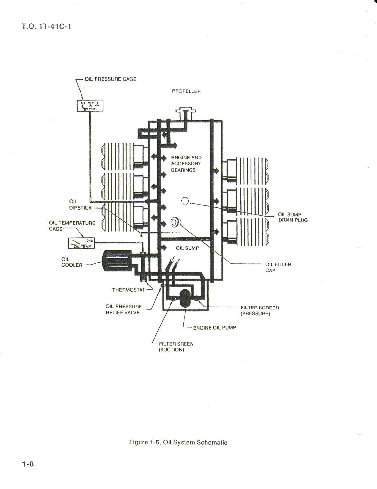
Figure 1-5.
FILTER SREEN
(sucTroN)
OilSystem
Schematic

T.O. 1T-41C-1
FUEL
OR^IN
pUGL
lffil
er-rE(C€s8
*At{ovAPoR
M€CIIANICAL
-
-
--
lrxloE
ELCSIBCAT
-
--
IANK
PLUG
Suppt
FU€L
SUMP
IBEFI
FIJEL
THFOrILE
y
ANO
AIB
UNII
FUEL
PLUG
NOZZLES
Figure 1-6. FuelSyslem
Schemalic
1-9

T.O. 1T-41 C-1
NOTE
o Wilh the
total usable
gallons,
46
lons.
luel
seleclor
fuel
and
model aircraft, lhe.
valve on
for
llight conditions
all
in level llight
knob is in-!he. erigine
ment and is.adidessible lhrouoh
t\**":-
a*gesrd6-ir
o
1968 model aircralt,
On
knob is
in
located
lhe lower
lelt
on the
corner.
BOTH, lhe
is 51
Juel-.sffdiff6r
compart-
fuel
the
inslrurnenl
strainer
the
panel
gal-
oil
preventing
thus
periods
ing
switch to lhe allernate flow
is
ol
approximately 2100
the auxiliary luel
erates the
position
purging
ternate engine
should malfunction. The
to OFF lrom
be held in
is
during
an excessively
low
of
pump
engine
pump
at its highest
used lor
hot
weather
operalion if
HIGH
the
HIGH when
rich
mixture
speed.
rate
rpm.
switch, labeled
at a
The
The
throtile
up
rale.
engine
posiiion
used.
NOTE
priming,
operations,
the engine-driven pump
swilch
is
spring-loaded
and
must
dur-
pump
setting
position
HIGH,
The
HIGH
for vapor
lor
or
therelore
will
of
op-
al-
Engine-Driven
The
engine-driven luel
provides
conditions.
lure
particularly
The mixture unit
engine-driven
through a
control
aulomatic
lt
control
at
mechanical
knob.
Fuel Pump
luel
provides
throughoul the
low
and
is
fuel
ir':Y"'i"%3
Should the aneroid
pump
luel
position
on LOW accompanied by
may be
Auxiliary
An electric
lor
starting and
lailure
vapor
(figure
is
The
pump
on lhrottle
setting
LOW
cruise
luel
the
causes
ol the engine-driven
purging.
1-2),located
guarded,
a
down
al one ol
and the auxiliary
position,
llight
pump.
idle
the auxiliary
lail, it willfailto
use of
and
required
Fuel
auxiliary
lor
The
three-position, center-ofl
position,
two
position.
suff
operation with
When
position,
Pump
icient luel f low is
the throttle
a
pump
has an aneroid
mixture for existing ambient
a more
desirable
luel
operalional range,
power
idle
also an
pump
settings.
integral
controlling
part
fuel llow
linkage from the
in
the engine-driven
LEAN
FULL
lhe
auxiliary
lhe
.
pump
luel
engine
auxiliary
on the
lelt lower switch
labeled
possible
With
the
fuel
a
microswitch
pump
luel
luelpump
manual
supplies
operalion
luel
{uel
LOW,
speeds
leaning
luel
following
pump
pump
operates lhe
depending
lhroltle al a cruise
pump
lailed
switch
provided
engine-driven
is moved
is
tripped
low raie
f
towards
lo
which
mix-
of the
mixture
flow
and for
switch
panel,
switch.
in
the
lor
which
reduce,
lf
the auxiliary
turned
engine
knob
ports
The
auxiliary
engine
the auxiliary
pump
air ralio will
is running
bolh functioning,
Manual
A
manual
panel
the engine.
engine induction manilolds
Fuel
The
tors
(f
(figure
Quantity
two electrically
are located
igure
1-4).
with
on
stopped,
not
at
will llood
luel
luel
result.
Primer
primer,
1-2), is
lt
sprays
The instruments
the tanks lrom
ters. The
level
master
indicators
lransmitters in
switch is ON.
quantity
Fuel
in
stabilized straight
ELECTRICAL
Electrical
current
driven
energy is
syslem
alternator. A 12-volt
pump
fuel
the master
and
FULL
LEAN,
luelwill
and
pump
during
pump
located
luel
lndicator
operated
on
lhe right
empty
receive
each wing
NOTE
indicators
SYSTEM
supplied
powered
and
an excessively
provided
to lull
and levetllight.
by
switch
is
switch
accidenily
the mixture
the cylinder
drain
overboard.
is
not
used
normal
on the left
operations.
the
engine-driven
to
into
the
lor
improved
aid in
elbows
fuelquantity
instrument
indicate
graduated
their inputs
lank
are accurate
by
14-voll,
a
a 60-ampere,
bafiery, located
ON,
control
intake
while
rich luel-
lower
starts.
the
from luel
any
time the
only
the
the
With
luel
switch
slarting
ol
lhe
indica-
panel
fuel
quar-
in
direct
engine-
alt of
in
1-10

T.0.
1T-41
C-1
USABLE
TANK NO.
LEFT WING
RIGHT
lhe
cal
nate
nator
Power is
a splil
conlains
WING
rear cabin
power
lor starting.
source ol electrical
regulalor lailure.
or
supplied
bar
bus
lhe
1
1
bulkhead,
(figure 1-8). The
strobe
ALL
CONDITIONS
lt
lo all electricalcircuits through
lighls,
ceiver, transponder, and
primary
The
tem circuils.
sides ol
when
nected,
power
a
circuit to
lronic
damaging the
equipment.
bus
contains
the
With
bus are
masler switch ON, both
the
normally
either an exlernal
ignition
lhe
or
contactor automatically
electronic bus.
the
circuils
prevents
semiconductors
switch
QUANTTY
FUEL
FUEL
FLIGHT
gal.
23
gal.
23
Figure 1-7. Fuei
is
used to supply
also serves as
power
in
case
eleclronic
VHF radio, VOR re-
pitot
lhe
all olher
power
is turned to START,
heal
electrical sys-
powered.
source
However,
deactivates lhe
lsolaiing the
lransient
vollages
in
the
electronic
ADDITIONAL
USABLE
(LEVEL
Quantity
electri-
an alter-
ol alter-
bus
circuits.
is con-
elec-
lrom
DATA
2.5
2.5
(U.S.
FUEL
FLTGHT)
gal.
gal.
Dala
Ammeler
All
indicates
or lrom
tween
inslrument
meler
the alternator
tery is in
or discharge
tions ol
GALLONS)
(U.S.
aircralt
lhe amount
the
the luel
will
a normal
an electrical
A weak
period
This
is normal;
untilthe
o[ 0
to +2
UNUSABLE
(LEVEL
Gallons)
are
equipped
battery.
quantity
panel
remain
is
operating
rates
battery
may
cause a high
ammeler
needle
FUEL
FLIcHT)
gal.
0.5
gal.
0.5
ol current
The
(ligure
within
state
of charge.
lor
system
NOTE
or
however,
is within
widths.
TOTAL
with
an ammeter
llowing
ammeter
indicators
1-4).
Normally,
0 to
+2 needle widths
properly
Extreme
any
duration
mallunction.
prolonged
a
ammeter reading.
not
do
the normalrange
FUEL
VOLUME
EACH
gal.
26.0
gal.
26.0
either
is
located
on
the right
the am-
and the
are indica-
starting
take
that
to
be-
il
bat-
charge
oll
Master
The master
the
crall, the
on
1969
piece
switch during
Switch
switch controls electrical
aircraft electrical syslem. On
push-pull
switch
lell
the
model
split switch
is
a
lower switch
aircrafl, the master switch
which
normal operations.
NOTE
On 1969 model aircrafl, the
switch may be benelicial
siluations. The lelt
connecl
disconnects the
the alternator
switch
battery.
1968 model
lype and
panel
(ligure
should be
split
during abnormal
serves
while
lhe
power
air-
is located
1-2).
On
is a two-
used as one
master
to dis-
right
side
to
External
ground
A
permit
cold
on
behind
be ON
lhe use
wealher
lower
the
an
belore
Belore
power
nal
personnel
danger
Power
service
of
slarting.
lell
access
connecling
starting
source,
are
area.
Receptacle
plug
receptacle
an exlernal
The
receptacle
side
ol
the
engine
plate.
The
masler
an external
WARNING
the
engine
be
sure
well
clear
is inslalted
power
compartment,
power
using
thal all
of
the
source
is located
swilch
source.
an exter-
ground
propeller
to
lor
should
1-1 1

T.O. 1T-41C-1
REGUTATOR
COOE
ctRcun
o
rusr
O
o,ooe
{*
cePectroR
{}
RESISTOR
AIEFINATOfi
FEiE;G--GRoUNO
ijouiifrY
conracroR
SREAKEF|
-t
SEFVICE
PLUO
TO
NAVtGAItON
uoHT
ctncLnr
BRE X€F
rGNlTrolt
STARTEFI
swTo{
rOruRN I EANK
TNOTCA'OR
IO
FU€L
INDICATORS
IO
iltr
^r[a,
AUO
C|GAR
iiurli?iiciii'ift,qxrn
TO
LAt{ONG e TAx
uoxrs
IO DOtlE LIGHI
IO I}ISTRUM€NI
cof,iP^sg
lo
lr^vtc rloN
lo
rcltmoN
SWrclr
10 wlNG FI.AP
POStnOil ftDTCATOR
IO
AUXILIAFY
TO
WilIG
TO IRANSPONOEF
TO NAVIGATION
SYSTEM
lo
sTFroSE
ro
vHF
UNUS€D
AMP
BR€AX€R rocAnoN
TO
P|IOT
Q{JAXTIW
UGHTER
I
LtGHls
LTGHIS
srAFrER
FUEL PUMP
FI.AP
SYSI€M
Lr6Ht3
colrMuNtc^Tlolt
clRCU|r
HEAI
SYST€M
1-12
Figure
1
-8.
Electrical
System Schemalic

T.O. 1T-41C-1
Use
ol other lhan a 12-volt
may
damage eleclrical
ground
corporales
service
lhe external source
service
properly.
plug
plug
polarity
is
connected
receplacle circuit
protection.
will llow only
Circuit Breakers and
The majority ol electrical circuils
protected
on
the
tions are lhe external
circuit
the battery.
lf
resel once il
lions exist.
alter being
it
again.
as soon as conditions
"push
by
lell lower
which
circuit breaker
a
lo
switch
prolecled
are
no
ll
the
reset, do not attempt lo
Terminale
resel"
panel
power
pops
other eleclrical
circuit breaker
the
power
systems.
Power
lo lhe
Fuses
in
the aircralt
circuil
permit.
breakers
(ligure
circuit and
by luses
oul,
mission and
source
if
aircralt
1-2). Excep-
the clock
located near
it may be
mallunc-
pops
reset
NOSEWHEEL STEERING SYSTEM
Nosewheel
ol the
up
to approximately
lral, aller
maximum
center when dilf
damper
BRAKE
hydraulic
The
individually operaled
are
sure
to the upper
pedals.
cylinders,
main landing
tached
transmits hydraulic
wheel
right
steering
rudder
pedals.
which it
delleclion
erential
provided
is
SYSTEM
disc
Depressing the
resulting in a braking
gear
to each of lhe
brake cylinder,
seat brake
is accomplished
The nosewheel
10
degrees each
becomes
lree wheeling to
ol 30 degrees
braking is
minimize nosewheelshimmy.
to
brakes on the
by applying
portion
pedals
wheels. A masler cylinder at-
pressure
thus
pedals
either set
of
activates
lelt
seal
the respective
to
applying brakes.
are connected
through
is sleerable
side ol
right
A shimmy
used.
main
toe
ol
the
aclion on lhe
(pilot)
The
in-
lrom
the
located
out
land
lelt ol
or
wheels
rudder
brake
pedals
by
are
use
neu-
pres-
main
The
me-
chanical
pressure
mitted
Parking
The
left
set
nism
master
bolh master
locks
is.lurned
the
position.
handle
position
a
position.
WING
The
controlled
lower
loaded
motor
cables and
lrom
located
cally-operated
in
degrees
grees.
linkage
applied
mechanically
ll
sharper
a
made
mechanism,
the
turn
rolling.
on a locked
wheel,
dangerous
be apparenl.
wheel
with
rate
of
in
this manner,
Any
lire or
rolls,
mittently.
evenly,
and
Brake
parking
lower
the
is
lhe handle
parking
brake
switch
brakes. The
connected
cylinders.
cylinder
and released.
handle
To release
90
degrees
and let it return
FLAP
wing llaps
by
a three-position
switch
panel
to the
raises
that
push-pull
shorts
on
and
the
ol
to
to
lurn
the
use
pilot's
lhe
the
right
to
lhe
is
desired
rudder
lhe
brakes
lurn desired.
keep
attempt
inside
because
To
release
Apply
cautiously
panel
Pulling
in
to
wheel
strut.
This
the
make
the inside
the
handle
(ligure
handle-and-rachet
by
a
cable
out
piston
position
this
To
out
and
parking
the
clockwise
to
SYSTEM
are
electrically
(figure
olf
or lowers
1-3).
position,
rods.
overheal
circuit
llap
llap
breaker
posilion
extension
brake
pedals
seat
masler
cylinders.
than can be
pedal
steering
to establish
While
lhe inside wheel
pivot
may
damage
sure
brakes
at
all
is located
lhe
damage
particularly
ii
that
the inside
brake
smoothly,
limes.
1-2)
and is
making
may
beneath
to linkage
lhe handle
rods
and
until
set
the
brakes,
turn il
to the
brake, rotate
to the
the
original
operafed
switch on
This
swilch,
controls
the llaps
The
by
panel.
indicator
by means
motor is
a circuit
is calibrated
lrom
0
pedals,
is
trans-
a
aircrall
lhe
nol
inter-
used
mecha-
at
depresses
the rachel
handte
lhe
6 o'clock
9 o'clock
retracted
and are
the
spring-
an
eleclric
protected
breaker
The
electri-
40 de-
to
and
the
lo
the
pull
the
right
of
1-13
 Loading...