

Cessna T182 1982 Pilot Operating Handbook

.,-:~
.~
PILOT'S
OPERATING
HANDBOOK
I and
FAA
APPROVED
AIRPLANE
FLIGHT
MANUAL
o
CESSNA
AIRCRAFT COMPANY
I I1982 MODEL 1182
THIS DOCUMENT MUST
BE
Serial
No.
I
$')"
tog
lOy
CARRIED
IN
THE
AIRPLANE
AT
ALL
TIME~.
Registration
No:'J
'ret"
fP
t
THIS
HANDBOOK INCLUDES
THE
MATERIAL
REQUIRED TO
BE
FURNISHED TO
THE
PILOT
BY
CAR PART 3 AND CONSTITUTES
THE
FAA
APPROVED
AIRPLANE
FLIGHT
MANUAL.
COPYRIGHT ©
1981
CESSNA
AIRCRAFT COMPANY
WICHITA,
KANSAS,
USA
f)
Member
of
GAMA
21
August
1981.

THIS
MANUAL
WAS
PROVIDED
FOR THE
AIRPLANE
IDENTIFIED
ON
THE TITLE
PAGE
ON
_
SUBSEQUENT
REVISIONS
SUPPLIED
BY
CESSNA
AIRCRAFT
COMPANY
MUST
BE
PROPERLY
IN-
SERTED.
CESSNA
AIRCRAFT
COMPANY,
PAWNEE
DIVISION
Cessna
Aircraft

CESSNA
CONG
RA
TULA
TIONS
MODEL
T182
CONGRATULATIONS
• • • •
Welcome
to
the
ranks
of
Cessna
owners!
Your
Cessna
has
been designed and
constructed
to
give
you
the
most
in
performance,
economy,
and
comfort.
It
is
our
desire
that
you
will
find
flying
it,
either
for
business
or
pleasure, a pleasant and
profitable
experience.
This Pilot's
Operating
Handbook
has
been
prepared
as a guide
to
help
you
get
the
most
pleasure and
utility
from
your
airplane.
It
contains
information
about
your
Cessna's
equipment,
operating
procedures,
and
performance;
and suggestions
for
its servicing and
care. We
urge
you
to
read it
from
cover
to
cover,
and
to
refer
to
it
frequently.
Our
interest
in
your
flying
pleasure
has
not
ceased
with
your
purchase
of
a Cessna.
Worldwide,
the Cessna
Dealer
organization
backed
by the Cessna
Customer
Services
Department
stands ready
to
serve you. The
following
services are
offered
by most Cessna
Dealers:
•
THE
CESSNA
WARRANTY,
which
provides
coverage
for
parts and
labor,
is
available at
Cessna Dealers
worldwide.
Specific
benefits
and
provisions
of
warranty,
plus
other
important
benefits
for
you,
are
contained
in
your
Customer
Care Program
book,
supplied
with
your
airplane.
Warranty
service
is
available
to
you
at
authorized
Cessna
Dealers
throughout
the
world
upon
presentation
of
your
Customer
Care Card
which
establishes
your
eligibility
under
the
warranty.
•
fACTORY-TRAINED
PERSONNEL
to
provide
you
with
courteous
expert
service.
•
fACTORY-APPROVED
SERVICE
EQUIPMENT
to
provide
you
efficient
and accurate
workmanship.
• A STOCK
Of
GENUINE CESSNA SERVICE PARTS
on
hand
when
you
need
them.
•
THE
LATEST
AUTHORITATIVE
INFORMATION
fOR
SERVICING CESSNA
AIR-
PLANES, since Cessna Dealers have all
of
the
Service
Manuals
and Parts Catalogs,
kept
current
by
Customer
Care Service
Information
Letters and
Customer
Care News
Letters,
published
by
Cessna
Aircraft
Company.
We
urge
all Cessna
owners
to
use
the
Cessna
Dealer
Organization
to
the fullest.
A
current
Worldwide
Customer
Care
Directory
accompanies
your
new
airplane. The
Directory
is
revised
frequently,
and a
current
copy
can be
obtained
from
your
Cessna
Dealer.
Make
your
Directory
one
of
your
cross-country
flight
planning
aids; a
warm
welcome
awaits
you
at
every
Cessna
Dealer.
21
August
1981

PERFORMANCE
-
CESSNA
SPECIFICA
TIONS
MODEL
T182
PERFORMANCE
-
SPECIFICATIONS
SPEED:
Maximum
at
20,000
Ft
168
KNOTS
Cruise,
75%
Power
at
20,000
Ft
158
KNOTS
Cruise,
75%
Power
at
10,000
Ft
145
KNOTS
CRUISE:
Recommended
lean
mixture
with
fuel
allowance
for
engine
start,
taxi,
takeoff,
climb
and
45
minutes
reserve.
75%
Power
at
20,000
Ft
.Range
745
NM
88
Gallons
Usable
Fuel
Time
4.9
HRS
75%
Power
at
to,OOO
Ft
.Range
725
NM
88
Gallons
Usable
Fuel
Time
5.1
HRS
Maximum
Range
at
20,000
Ft
.Range
885
NM
88
Gallons
Usable
Fuel
Time
7.3
HRS
Maximum
Range
at
10,000
Ft
.Range
920 NM..
88
Gallons
Usable
Fuel
Time
8.4
HRS
RATE
OF
CLIMB
AT
SEA
LEVEL
965
FPM
CERTIFICATED
MAXIMUM
OPERATING
ALTITUDE
20,000
FT
TAKEOFF
PERFORMANCE:
Ground
Roll
. . . . . . . . . .
790
FT
Total
Distance
Over
50-Ft
Obstacle
1475
IT
LANDING
PERFORMANCE:
Ground
Roll
. . . . . . . . . .
590
FT
Total
Distance
Over
50-Ft
Obstacle
1350
FT
STALL
SPEED
(KCAS):
Flaps
Up,
Power
Off
54
KNOTS
Flaps
Down,
Power
Off
49
KNOTS
MAXIMUM
WEIGHT:
Ramp
3112
LBS
Takeoff
3100
LBS
Landing
2950
LBS
STANDARD
EMPTY
WEIGHT:
Turbo
Skylane
1740
LBS
Turbo
Skylane
II
. . .
1793
LBS
MAXIMUM
USEFUL
LOAD:
Turbo
Skylane
. . . .
1372
LBS
Turbo
Sky
lane
II
. . .
1319
LBS
BAGGAGE
ALLOWANCE
200
LBS
WING
LOADING:
Pounds/
Sq
Ft
17.8
POWER
LOADING:
Pounds/
HP
13.2
FUEL
CAPACITY:
Total
92
GAL
OIL
CAPACITY
.....
9
QTS
ENGINE:
Turbocharged
Avco
Lycoming
0-540-L3C5D
235
BHP
at
2400
RPM
PROPELLER:
2-Bladed
Constant
Speed.
Diameter
82
IN
Performance
with
an
optiona.13-bladed
propeller
is
essentially
the
Same
as
shown
above.
The
above
performance
figures
are
based
on
the
indicated
weights,
standard
atInospheric
conditions,
level
hard-surface
dry
runways,
and
no
wind.
They
are
calculated
values
derived
from
flight
tests
conducted
by
the
Cessna
Aircraft
Company
under
carefully
documented
conditions
and
will
vary
with
individual
airplanes
and
numerous
factors
affecting
flight
performance.
ii
21
August
1981
I

CESSNA
COVERAGE/
REVISIONS/
MODELT182
LOG
OF
EFFECTIVE
PAGES
COVERAGE
The Pilot's
Operating
Handbook
in
the
airplane at
the
time
of
delivery
from
Cessna
Aircraft
Company
contains
information
applicable
to
the 1982
Model
T182
airplane designated by
the
serial
number
and registration
number
shown
on
the
Title
Page
of
this
handbook.
This
information
is
based
on data available at
the
time
of
publication.
REVISIONS
Changes
and/or
additions
to
this
handbook
will
be covered by revisions
published
by Cessna
Aircraft
Company. These revisions are
distributed
to
owners
of
U.
S.
Registered aircraft
according
to
FAA records at the
time
of
revision issuance.
Revisions should be
examined
immediately
upon
receipt and
incorporated
in this
handbook.
NOTE
It
is
the
responsibility
of
the
owner
to
maintain
this
handbook
in a current
status
when
it
is
being
used
for
operational
purposes.
Owners
should
contact
their
Cessna Dealer
whenever
the
revision status
of
their
handbook
is
in
question.
A revision bar
will
extend
the
full
length
of
new
or
revised text
and/or
illuSlrations added on
new
or
presently existing pages. This bar
will
be located adjacent to
the
applicable revised area on
the
outer
margin
of
the
page.
All revised pages
will
carry
the
revision
number
and date
on
the applicable page.
The
following
log
of
Effective
Pages
provides
the
dates
of
issue for
original
and revised pages, and
a listing
of
all pages in the
handbook.
Pages
affected
by
the
current
revision are
indicated
by an
asterisk
('j
preceding
the
pages listed.
LOG
OF
EFFECTIVE PAGES
Dates
of
issue
for
original
and revised pages are:
,
Original
21
August
1981
Revision 1 4
December
1981
Revision 2 4 February
1982
Page
Date
Title
21
August
1981
Assignment Record
21
August
1981
i
thru
ii
21
August
1981
'iii
thru
iv 4 February
1982
v
21
August
1981
vi
Blank
21
August
1981
1-1
thru
1-9
...•......
21
August
1981
1-10 Blank
21
August
1981
2-1
...........•......
21
August
1981
2-2
Blank
21
August
1981
2-3
21
August
1981
2-4 4
December
1981
2-5
thru
2-8
21
August
1981
2-9
4
December
1981
Page
2-10
thru
2-11
2-12 Blank
3-1
thru
3-3
3-4
thru
3-5
3-6
thru
3-14
'3-15
thru
3-16
3-17
thru
3-18
4-1
thru
4-2
4-3
4-4
thru
4-10
4-11
4-12
thru
4-20
4-21
4-22
thru
4-24
Date
21
August
1981
21
August
1981
21
August
1981
4
December
1981
21
August
1981
4 February
1982
21
August
1981
21
August
1981
4
December
1981
21
August
1981
4
December
1981
21
August
1981
4
December
1981
21
August
1981
21
August
1981
Revision
2 - 4
February
1982/
D1216R2-13PH-CES-400-2/B2
iii

LOG
OF
EFFECTIVE
PAGES
CESSNA
MODEL
T182
LOG OF
EFFECTIVE
PAGES
(Continued)
Page
Date
5-1
21
August
1981
5-2 Blank
21
August
1981
5-3
thru
5-7
21
August
1981
5-8 Blank. . . . .
21
August
1981
5-9
thru
5-10 4
December
1981
5-11
21
August
1981
5-12 4
December
1981
5-13
thru
5-32
21
August
1981
5-33 4
December
1981
5-34 Blank
21
August
1981
6-1
21
August
1981
6-2 Blank
21
August
1981
6-3
lhru
6-29
21
August
1981
Page
Date
6-30 Blank
7-1
thru
7-42
8-1
8-2 Blank
8-3
thru
8-19
8-20 Blank
9-1
thru
9-3
9-4 Blank
21
August
1981
21
August
1981
21
August 1981
21
August
1981
21
August
1981
21
August
1981
21
August
1981
21
August
1981
NOTE
Refer
to
Section 9 Table
of
Contents
for
supplements
applicable
to
optional
sys-
tems.
'-
21
August
1981
Revision
2 - 4
February
1982
iv

TABLE
OF
CONTENTS
CESSNA
MODEL
T182
TABLE
OF
CONTENTS
SECTION
GENERAL 1
LIMITATIONS
2
EMERGENCY PROCEDURES 3
NORMAL
PROCEDURES 4
\
PERFORMANCE. 5
WEIGHT & BALANCE/
EQUIPMENT
LIST
6
AIRPLANE
&
SYSTEMS
DESCRIPTIONS 7
AIRPLANE
HANDLING,
SERVICE &
MAINTENANCE
8
SU
PPLEMENTS
(Optional
Systems
Description
&
Operating
Procedures)
I (
n1
2
6'
flz('s
-
11}1J4
\1\:,
"i.~
tjr
IJ
G
'36
ttl"'·
.;.;
v/(vi
blank)
21
August
1981
9

CESSNA
SECTION
1
MODELT182
GENERAL
SECTION 1
GENERAL
TABLE OF
CONTENTS
Page
Three
View
..
1-2
Introduction
. . 1-3
Descriptive
Data
1-3
Engine
..
1-3
Propeller
(2-Bladed)
1-3
Propeller
(3-Bladed)
1-3
Fuel
. . . . . . . . 1-3
Oil
1-4
Maximum
Certificated
Weights
1-5
Standard
Airplane
Weights
. . 1-5
Cabin
And
Entry
Dimensions
. 1-5
Baggage
Space
And
Entry
Dimensions
1-5
Specific
Loadings
1-5
Symbols,
Abbreviations
And
Terminology
1-6
General
Airspeed
Terminology
And
Symbols
1-6
Meteorological
Terminology
1-6
Engine
Power
Terminology
. . . . . . . . 1-7
Airplane
Performance
And
Flight
Planning
Terminology
1-7
Weight
And
Balance
Terminology
. . . . . . . . . . . 1-7
WARNING
PITOT
HEATER
MUST
BE
ON
WHEN
OPERATING
BelOW
40°F
IN
INSTRUMENT
METEOROLOGICAL
CONDITIONS.
0890018.2
21
August
1981
1-1

SECTION
1
CESSNA
GENERAL
MODEL
T182
r
9'-3"
MAX.
o
I
I
28'-5"--------
I
11
'-8"
'1
NOTES,
1.
Dimensions shown are based on standard
a
empty
weight
and
proper
nose
gear
and
tire
inflation.
2. Wing
span
shown
with
strObe
lights
installed.
3.
Maximum
height shown
with
nose gear
depressed as far
as
possible
and
flashing
beacon installed.
4. Wheel base length
is
66
1/2"
5.
Propeller ground clearance
is
103/4"
6. Wing
area
is
174
square
feet.
7.
Minimum
tuming
radius
I *
pivot
point
to
outboard
wing
tip)
is
27'-7"
umJiIITITl~1llII"'TIJJI!iIITIlm
PIVOT
POINT
__
PIVOT
POINT
*
1------------36'-0"------------
<.r:=..::=::=
_
Figure
1-1.
Three
View
21
August
1981 1-2

CESSNA
SECTION
1
MODEL
T182
GENERAL
INTRODUCTION
(
This
handbook
contains 9 sections,
and
includes
the
material
required
to
be
furnished
to
the
pilot
by
CAR
Part
3.
It
also
contains
supplemental
data
supplied
by
Cessna
Aircraft
Company.
Section 1 provides
basic
data
and
information
of
general
interest.
It
also
contains
definitions
or
explanations
of
symbols,
abbreviations,
and
terminology
commonly
used.
DESCRIPTIVE
DATA
ENGINE
Number
of
Engines:
1.
Engine
Manufacturer:
A
vco
Lycoming.
Engine
Model
Number:
0-540-L3C5D.
Engine
Type:
Turbocharged,
direct-drive,
air-cooled,
horizon
tally-
opposed,
carburetor
equipped,
six-cylinder
engine
with
541.5
cu.
in.
displacement.
Horsepower
Rating
and
Engine
Speed:
235
rated
BHP
at
31
inches
Hg
and
2400
RPM.
.<k
PROPELLER
(2-BLADED)
Propeller
Manufacturer:
McCauley
Accessory
Division.
Propeller
Model
Number:
B2D34C219/90DHB-8.
Number
of
Blades:
2.
Propeller
Diameter,
Maximum:
82
inches.
Minimum:
80.5
inches.
Propeller
Type:
Constant
speed
and
hydraulically
actuated,
with a low
pitch
setting
of
15.80 and a high
pitch
setting
of
31.90 (30
inch
station).
PROPELLER
(3-BLADED)
Propeller
Manufacturer:
McCauley
Accessory
Division.
Propeller
Model
Number:
B3D32C407/82NDA-3.
Number
of
Blades:
3.
Propeller
Diameter,
Maximum:
79
inches.
Minimum:
78
inches.
Propeller
Type:
Constant
speed
and
hydraulically
actuated,
with a low
pitch
setting
of
16.00 and a high
pitch
setting
of
31.70 (30
inch
station).
FUEL
Approved
Fuel
Grades
(and
Colors):
100LL
Grade
Aviation
Fuel
(Blue).
100
(Formerly
100/130)
Grade
Aviation
Fuel
(Green).
21
August
1981
1-3

SECTION
1
CESSNA
GENERAL
MODEL
T182
NOTE
Isopropyl
alcohol
or
ethylene
glycol
monomethyl
ether
(
1
may
be
added
to
the
fuel
supply.
Additive
concentrations
shall
not
exceed
1%
for
isopropyl
alcohol
or
.15%
for
I
ethylene
glycol
monomethyl
ether.
Refer
to
Section 8 for
additional
information.
Total
Capacity:
92
gallons.
Total
Capacity
Each
Tank:
46
gallons.
Total
Usable:
88
gallons.
NOTE
To
ensure
maximum
fuel
capacity
when
refueling
and
minimize
cross-feeding
when
parked
on a sloping
surface,
place
the
fuel
selector
valve
in
either
LEFT
or
RIGHT
position.
OIL
Oil
Grade
(Specification):
(
MIL-L-6082
Aviation
Grade
Straight
Mineral
Oil:
Use
to
replenish
supply
during
first
25
hours
and
at
the
first
25-hour
oil
change.
Continue
to
use
until a total
of
50
hours
has
accumulated
or
oil
consumption
has
stabilized.
MIL-L-22851
Ashless
Dispersant
Oil:
This
oil
must
be
used
after
first
50
hours
or
oil
consumption
has
stabilized.
Recommended
Viscosity
For
Temperature
Range:
MIL-L-6082
Aviation
Grade
Straight
Mineral
Oil:
All
temperatures,
use
SAE
20W-50
or
Above
16°C
(60°F),
use
SAE
50
-1°C
(30°F)
to
32°C
(90°
F),
use
SAE
40
-18°C
(O°F)
to
21°C
(70°F),
use
SAE
30
Below
-12°C
(10°F),
use
SAE
20
MIL-L-22851
Ashless
Dispersant
Oil:
All
temperatures,
use
SAE
20W-50
or
Above
16°C
(60°F),
use
SAE
40
or
SAE
50
-1°C
(30°F)
to
32°C
(90°F),
use
SAE
40
-18°C
(O°F)
to
21°C
(70°F),
use
SAE
40
or
SAE
30
Below
-12°C
(10°F),
use
SAE
30
J \
Oil
Capacity:
Sump: 8 Quarts.
Total: 9 Quarts.
21
August
1981
1-4

CESSNA
SECTION
1
MODEL
T182
GENERAL
MAXIMUM
CERTIFICATED
WEIGHTS
Ramp:
3112
lbs.
Takeoff:
3100
lbs.
Landing:
2950
lbs.
Weight
in
Baggage
Compartment:
Baggage
Area"
A"
(or
passenger
on
child's
seat) -Station
82
to
109: 120
lbs.
See
note
below.
.
Baggage
Area
"B" -Station
109
to
124: 80
lbs.
See
note
below.
Baggage
Area
"C" -Station
124
to
134: 80
lbs.
See
note
below.
NOTE
The
maximum
allowable
combined
weight
capacity
for
baggage
in
areas
A,
Band
C
is
200
lbs.
The
maximum
allowable
weight
capacity
for
baggage
in
areas
Band
Cis
80
lbs.
STANDARD
AIRPLANE
WEIGHTS
Standard
Empty
Weight,
Turbo
Skylane:
1740
lbs.
Turbo
Sky
lane
II: 1793
lbs.
Maximum
Useful
Load,
Turbo
Skylane:
1372
lbs.
Turbo
Skylane
II: 1319
lbs.
CABIN
AND
ENTRY
DIMENSIONS
Detailed
dimensions
of
the
cabin
interior
and
entry
door
openings
are
illustrated
in
Section
6.
BAGGAGE
SPACE
AND
ENTRY
DIMENSIONS
Dimensions
of
the
baggage
area
and
baggage
door
opening
are
illustrated
in
detail
in
Section
6.
SPECIFIC
LOADINGS
Wing
Loading:
17.8
lbs.!
sq.
ft.
Power
Loading:
13.2
lbs./
hp.
21
August
1981
1-5

SECTION
1
CESSNA
GENERAL
MODEL
T182
SYMBOLS,
ABBREVIATIONS
AND
TERMINOLOGY
GENERAL
AIRSPEED
TERMINOLOGY
AND
SYMBOLS
KCAS
Knots
Calibrated
Airspeed
is
indicated
airspeed
corrected
for
position
and
instrument
error
and
expressed
in
knots.
Knots
calibrated
airspeed
is
equal
to
KT
AS
in
standard
atmosphere
at
sea
level.
KIAS
Knots
Indicated
Airspeed
is
the
speed
shown
on
the
airspeed
indicator
and
expressed
in
knots.
KTAS
Knots
True
Airspeed
is
the
airspeed
expressed
in
knots
relative
to
undisturbed
air
which
is
KCAS
corrected
for
altitude
and
temperature.
VA
Maneuvering
Speed
is
the
maximum
speed
at
which
full
or
abrupt
control
movements
may
be
used.
V
Maximum
Flap
Extended
Speed
is
the
highest
speed
FE
permissible
with
wing
flaps
in a prescribed
extended
position.
V
Maximum
Structural
Cruising
Speed
is
the
speed
that
NO
should
not
be
exceeded
except
in
smooth
air.
then
only
with
caution.
V
Never
Exceed
Speed
is
the
speed
limit
that
may
not
be
NE
exceeded
at
any
time.
V
Stalling
Speed
or
the
minimum
steady
flight
speed
at
s
which
the
airplane
is
controllable.
V
Stalling
Speed
or
the
minimum
steady
flight
speed
at
So
which
the
airplane
is
controllable
in
the
landing
configu-
ration
at
the
most
forward
center
of
gravity.
V
Best
Angle-of-Climb
Speed
is
the
speed
which
results
in
x
the
greatest
gain
of
altitude
in a given
horizontal
distance.
V
y
Best
Rate-of-Climb
Speed
is
the
speed
which
results
in
the
greatest
gain
in
altitude
in a given
time.
METEOROLOGICAL
TERMINOLOGY
OAT
Outside
Air
Temperature
is
the
free
air
static
temperature.
21
August
1981
1-6

CESSNA
MODEL
T182
Standard
Temperature
Pressure
Altitude
SECTION
1
GENERAL
It
is
expressed
in
either
degrees
Celsius
or
degrees
Fah-
renheit.
Standard
Temperature
is
15°C
at
sea
level
pressure
alti-
tude
and
decreases
by
2°C
for
each
1000
feet
of
altitude.
Pressure
Altitude
is
the
altitude
read
from
an
altimeter
when
the
altimeter's
barometric
scale
has
been
set
to
29.92
inches
of
mercury
(1013
mb).
ENGINE
POWER
TERMINOLOGY
BHP
Brake
Horsepower
is
the
power
developed
by
the
engine.
RPM
Revolutions
Per
Minute
is
engine
speed.
MP
Manifold
Pressure
is a pressure
measured
in
the
engine's
induction
system
and
is
expressed
in
inches
of
mercury
(Hg).
AIRPLANE
PERFORMANCE
AND
FLIGHT
PLANNING
TERMINOLOGY
Demonstrated
Crosswind
Velocity
Usable
Fuel
Unusable
Fuel
GPH
NMPG
g
Demonstrated
Crosswind
Velocity
is
the
velocity
of
the
crosswind
component
for
which
adequate
control
of
the
airplane
during
takeoff
and
landing
was
actually
demon-
strated
during
certification
tests.
The
value
shown
is
not
considered
to
be
limiting.
Usable
Fuel
is
the
fuel
available
for
flight
planning.
Unusable
Fuel
is
the
quantity
of
fuel
that
can
not
be
safely
used
in
flight.
Gallons
Per
Hour
is
the
amount
of
fuel
consumed
per
hour.
Nautical
Miles
Per
Gallon
is
the
distance
which
can
be
expected
per
gallon
of
fuel
consumed
at a specific
engine
power
setting
and/
or
flight
configuration.
g
is
acceleration
due
to
gravity.
WEIGHT
AND
BALANCE
TERMINOLOGY
deference
Reference
Datum
is
an
imaginary
vertical
plane
from
Datum
which
all
horizontal
distances
are
measured
for
balance
purposes.
21
August
1981
1-7

SECTION
1
GENERAL
Station
Arm
Moment
Center
of
Gravity
(C.G.)
C.G.
Arm
C.G.
Limits
Standard
Empty
Weight
Basic
Empty
Weight
Useful
Load
Maximum
Ramp
Weight
Maximum
Takeoff
Weight
Maximum
Landing
Weight
Tare
CESSNA
MODEL
T182
Station
is a location
along
the
airplane
fuselage
given
in
terms
of
the
distance
from
the
reference
datum.
Arm
is
the
horizontal
distance
from
the
reference
datum
to
the
center
of
gravity
(C.G.)
of
an
item.
Moment
is
the
product
of
the
weight
of
an
item
multiplied
by
its
arm.
(Moment
divided
by
the
constant
1000
is
used
in
this
handbook
to
simplify
balance
calculations
by
reduc-
ing
the
number
of
digits.)
Center
of
Gravity
is
the
point
at
which
an
airplane,
or
equipment,
would
balance
if
suspended.
Its
distance
from
the
reference
datum
is
found
by
dividing
the
total
moment
by
the
total
weight
of
the
airplane.
Center
of
Gravity
Arm
is
the
arm
obtained
by
adding
the
airplane's
individual
moments
and
dividing
the
sum
by
the
total
weight.
Center
of
Gravity
Limits
are
the
extreme
center
of
gravity
locations
within
which
the
airplane
must
be
operated
at
a
given
weight.
Standard
Empty
Weight
is
the
weight
of a standard
air-
plane,
including
unusable
fuel,
full
operating
fluids
and
full
engine
oil.
Basic
Empty
Weight
is
the
standard
empty
weight
plus
the
weight
of
optional
equipment.
Useful
Load
is
the
difference
between
ramp
weight
and
the
basic
empty
weight.
Maximum
Ramp
Weight
is
the
maximum
weight
approved
for
ground
maneuver.
(It
includes
the
weight
of
start,
taxi
and
runup
fuel.)
Maximum
Takeoff
Weight
is
the
maximum
weight
approved
for
the
start
of
the
takeoff
roll.
Maximum
Landing
Weight
is
the
maximum
weight
approved
for
the
landing
tOUChdown.
Tare
is
the
weight
of
chocks,
blocks,
stands,
etc.
used
when
21
August
1981
(
/
1-8

CESSNA
MODEL
T182
SECTION
1
GENERAL
(
weighing
an
airplane.
and
is
included
in
the
scale
read-
ings.
Tare
is
deducted
from
the
scale
reading
to
obtain
the
actual
(net)
airplane
weight.
{
(
21
August
1981
1-9/(1-10
blank)

CESSNA
SECTION
2
MODEL
T182
LIMITATIONS
SECTION 2
LIMITATIONS
TABLE OF
CONTENTS
Page
Introduction
. . . . . . . .
2-3
Airspeed
Limitations
2-4
Airspeed
Indicator
Markings
2-5
Power
Plant
Limitations
2-5
Power
Plant
Instrument
Markings
2-6
Weight
Limits
. . . . .
2-7
Center
Of
Gravity
Limits
2-7
Maneuver
Limits
2-7
Flight
Load
Factor
Limits
2-8
Kinds
Of
Operation
Limits
2-8
Fuel
Limitations
. . . . . 2-8
Maximum
Operating
Altitude
Limit
2-9
Other
Limitations
2-9
Flap
Limitations
2-9
Placards
.....
2-9
21
August
1981
2-1/(2-2
blank)

CESSNA
SECTION
2
MODELT182
LIMIT
ATIONS
INTRODUCTION
Section 2 includes
operating
limitations.
instrument
markings,
and
~,
basic
placards
necessary
for
the
safe
operation
of
the
airplane,
its
engine,
standard
systems
and
standard
equipment.
The
limitations
included
in
this
section
and
in
Section 9 have
been
approved
by
the
Federal
Aviation
Administration.
Observance
of
these
operating
limitations
is
required
by
Federal
Aviation
Regulations.
NOTE
Refer
to
Section 9 of
this
Pilot's
Operating
Handbook
for
amended
operating
limitations,
operating
procedures,
performance
data
and
other
necessary
information
for
airplanes
equipped
with
specific
options.
NOTE
The
airspeeds
listed
in
the
Airspeed
Limitations
chart
(figure
2-1)
and
the
Airspeed
Indicator
Markings
chart
(figure
2-2)
are
based
on
Airspeed
Calibration
data
shown
in
Section
5
with
the
normal
static
source,
with
the
exception
of
the
bottom
of
the
green
and
white
arcs
on
the
airspeed
indicator.
These
are
based
on a power-off
air-
speed
calibration.
If
the
alternate
static
source
is
being
used,
ample
margins
should
be
observed
to
allow
for
the
airspeed
calibration
variations
between
the
normal
and
alternate
static
sources
as
shown
in
Section
5.
Your
Cessna
is
certificated
under
FAA
Type
Certificate
No.
3A13
as
Cessna
Model
No.
T182.
21
August
1981
2-3

I
SECTION
2
CESSNA
LIMITATIONS
MODEL
T182
AIRSPEED
LIMITATIONS
Airspeed
limitations
and
their
operational
significance
are
shown
in
figure
2-1.
~
1\
SPEED KCAS
KIAS
REMARKS
VNE
Never Exceed Speed 175 178 Do
not
exceed this
speed
in
any operation.
VNO
Maximum
Structural
Cruising Speed
138 140
Do
not
exceed this
speed
except in smooth air, and
then
only
with
caution.
VA
Maneuvering Speed:
3100 Pounds
2600 Pounds
2100 Pounds
110
100
90
111
101
90
Do
not
make
full
or
abrupt
control
movements above
this speed.
VFE
Maximum
Flap Extended
Speed:
To 10
0
Flaps
10
0
-
FULL
Flaps
138
95
140
95
Do
not
exceed these speeds
with
the given flap settings.
Maximum
Window
Open
Speed
175
178
Do
not
exceed this
speed
with
windows open.
Figure
2-1.
Airspeed
Limitations
j
21
August
1981
Revision
1 - 4
Elecember
1981
2-4

CESSNA
SECTION
2
MODELT182
LIMITATIONS
AIRSPEED
INDICATOR
MARKINGS
Airspeed
indicator
markings
and
their
color
code
significance
are
shown
in
figure
2-2.
MARKING
KIAS
VALUE
OR
RANGE
SIGNIFICANCE
White
Arc
40 -95
Full
Flap Operating Range.
Lower
limit
is
maximum
weight
V
So
in
landing
configuration.
Upper
limit
is
maximum
speed permissible
with
flaps extended.
Green
Arc
48 - 140
Normal Operating Range. Lower
limit
is
maximum
weight Vs at most
forward
C.G.
with
flaps retracted. Upper
limit
is
maximum
structural
cruising speed.
Yellow
Arc
140-178
Operations
must
be conducted
with
caution and
only
in
smooth
air.
Red
Line
178
Maximum
speed
for
all operations.
Figure
2-2.
Airspeed
Indicator
Markings
POWER
PLANT
LIMITATIONS
Engine
Manufacturer:
Avco
Lycoming.
Engine
Model
Number:
0-540-L3C5D.
Maximum
Power:
235
BHP
rating.
Engine
Operating
Limits
for
Takeoff
and
Continuous
Operations:
Maximum
Engine
Speed:
2400
RPM.
Maximum
Manifold
Pressure:
31
in.
Hg.
Maximum
Cylinder
Head
Temperature:
500°F
(260°C).
Maximum
Oil
Temperature:
245°F
(118°C).
Oil
Pressure,
Minimum:
25
psi.
Maximum:
115
psi.
Fuel
Pressure,
Minimu'm:
3.0
psi.
Maximum:
30.0
psi.
'uel
Grade:
See
Fuel
Limitations.
Oil
Grade
(Specification):
MIL-L-6082
Aviation
Grade
Straight
Mineral
Oil
or
MIL-L-22851
Ashless
Dispersant
Oil.
21
August
1981 2-5

- - -
- -
-
- - -
-
--
- - -
- -
-
-
--
- - -
SECTION
2
CESSNA
LIMIT
ATIONS
MODEL
T182
Propeller
Manufacturer:
McCauley
Accessory
Division.
Propeller
Model
Number,
2-Bladed:
B2D34C219/90DHB-8
3-Bladed:
B3D32C407/82NDA-3.
Propeller
Diameter,
2-Bladed
Maximum:
82
inches.
2-Bladed
Minimum:
80.5
inches.
3-Bladed
Maximum:
79
inches.
3-Bladed
Minimum:
78
inches.
Propeller
Blade
Angle
at
30
Inch
Station,
2-Bladed
Low:
15.8
0
•
2-Bladed
High:
31.9
0
•
3-Bladed
Low:
16.0
0
•
3-Bladed
High:
31.7
0
•
POWER PLANT
INSTRUMENT
MARKINGS
Power
plant
instrument
markings
and
their
color
code
significance
are
shown
in
figure
2-3.
INSTRUMENT
RED
LINE
GREEN
ARC
RED LINE
MINIMUM
NORMAL
MAXIMUM
LIMIT
OPERATING
LIMIT
Tachometer
2100 -
2400
RPM
2400
RPM
Manifold
Pressure
17-25
31
in.Hg
in.Hg
Oil Temperature
100°-245°F
245°F
Cylinder
Head
200° -500°F
500°F
Temperature
Fuel
Pressure
3.0
psi
3.0 - 30.0 psi
30.0
psi
Oil
Pressure
25
psi
60-90
psi
115
psi
Suction
4.5
- 5.4
in.
Hg
Fuel Quantity
E
(2
Gal. Unusable
Each Tank)
)
J
j
I
Figure
2-3.
Power
Plant
Instrument
Markings
21
August
1981
2-6

CESSNA
SECTION
2
MODEL
T182
LIMITATIONS
WEIGHT
LIMITS
Maximum
Ramp
Weight:
3112
lbs.
Maximum
Takeoff
Weight:
3100
lbs.
Maximum
Landing
Weight:
2950
lbs.
Maximum
Weight
in
Baggage
Compartment:
Baggage
Area"
A"
(or
passenger
on
child's
seat) -Station
82
to
109: 120
lbs.
See
following
note.
Baggage
Area
"B" -Station
109
to
124: 80
lbs.
See
following
note.
Baggage
Area
"C" -Station
124
to
134: 80
lbs.
See
following
note.
NOTE
The
maximum
allowable
combined
weight
capacity
for
baggage
in
areas
A,
Band
C
is
200
lbs.
The
maximum
allowable
weight
capacity
for
baggage
in
areas
Band C is
801bs.
CENTER
OF
GRAVITY
LIMITS
Center
of
Gravity
Range:
Forward:
33.0
inches
aft
of
datum
at
2250
lbs.
or
less,
with
straight
line
variation
to
35.5
inches
aft
of
datum
at
2700
lbs.,
with
straight
line
variation
to
38.9
inches
aft
of
datum
at
2950
lbs.
(landing),
with
straight
line
variation
to
40.9
inches
aft
of
datum
at
3100
lbs.
(takeoff).
Aft: 46.0
inches
aft
of
datum
at
all
weights.
Reference
Datum:
Front
face
of
firewall.
MANEUVER
LIMITS
This
airplane
is
certificated
in
the
normal
category.
The
normal
category
is
applicable
to
aircraft
intended
for
non-aerobatic
operations.
~hese
include
any
maneuvers
incidental
to
normal
flying,
stalls
(except
whip
stalls),
lazy
eights,
chandelles,
and
steep
turns
in
which
the
angle
of
bank
is
not
more
than
60
0
•
\
Aerobatic
maneuvers,
including
spins,
are
not approved.
\
2-721
August
1981

SECTION
2
CESSNA
LIMITATIONS
MODEL
T182
FLIGHT
LOAD
FACTOR
LIMITS
Flight
Load
Factors:
*Flaps
Up: +3.8g,
-1.52g
*Flaps
Down:
+2.0g
*The
design
load
factors
are
150%
of
the
above,
and
in
all
cases,
the
structure
meets
or
exceeds
design
loads.
KINDS
OF
OPERATION
LIMITS
The
airplane
is
equipped
for
day
VFR
and
may
be
equipped
for
night
VFR
and/
or
IFR
operations.
FAR
Part
91
establishes
the
minimum
required
instrumentation
and
equipment
for
these
operations.
The
refer-
ence
to
types
of
flight
operations
on
the
operating
limitations
placard
reflects
equipment
installed
at
the
time
of
Airworthiness
Certificate
issuance.
Flight
into
known
icing
conditions
is
prohibited.
FUEL
LIMITATIONS
2
Standard
Tanks:
46.0 U.S.
gallons
each.
Total
Fuel:
92.0 U.S.
gallons.
Usable
Fuel
(all
flight
conditions):
88 U.S.
gallons.
Unusable
Fuel:
4.0 U.S.
gallons.
NOTE
To
ensure
maximum
fuel
capacity
when
refueling
and
prevent
cross-feeding
when
parked
on a sloping
surface,
place
the
fuel
selector
valve
in
either
LEFT
or
RIGHT
position.
Takeoff
and
land
with
the
fuel
selector
valve
handle
in
the
BOTH
position.
Operation
on
either
left
or
right
tank
is
limited
to
level
flight
only.
With
1/4
tank
or
less,
prolonged
uncoordinated
flight
is
prohibited
when
operating
on
either
left
or
right
tank
in
level
flight.
Approved
Fuel
Grades
(and
Colors):
lOOLL
Grade
Aviation
Fuel
(Blue).
100
(Formerly
100/130)
Grade
Aviation
Fuel
(Green).
I
I
I
)
\
"
21
August
1981 2-8

CESSNA
SECTION
2
MODEL
T182
LIMITATIONS
MAXIMUM
OPERATING
ALTITUDE
LIMIT
Certificated
Maximum
Operating
Altitude:
20,000
Ft.
OTHER
LIMITATIONS
FLAP
LIMITATIONS
Approved
Takeoff
Range:
0°
to
20°.
Approved
Landing
Range:
0°
to
FULL.
PLACARDS
The
following
information
must
be
displayed
in
the
form
of
composite
or
individual
placards.
1.
In
full
view
of
the
pilot:
(The
"DAY
-NIGHT-
VFR-IFR"
entry,
shown
on
the
example
below,
will
vary
as
the
airplane
is
equipped.)
The
markings
and
placards
installed
in
this
airplane
contain
operating
limitations
which
must
be
complied
with
when
operat-
ing
this
airplane
in
the
Normal
Category.
Other
operating
limita-
tions
which
must
be
complied
with
when
operating
this
airplane
in
this
category
are
contained
in
the
Pilot's
Operating
Handbook
and
FAA
Approved
Airplane
Flight
Manual.
No
acrobatic
maneuvers,
including
spins,
approved.
Flight
into
known
icing
conditions
prohibited.
This
airplane
is
certified
for
the
following
flight
operations
as
of
date
of
original
airworthiness
certificate:
DAY-NIGHT-VFR-IFR
2.
Near
airspeed
indicator:
MAX
SPEED -KIAS
MANEUVER
...
111
21
August
1981
Revision
1 - 4
December
1981
2-9

SECTION
2
CESSNA
LIMITATIONS
MODEL
T182
3.
On
control
lock:
CAUTION!
CONTROL
LOCK
REMOVE
BEFORE
STARTING
ENGINE
4.
On
the
f'lel
selector
valve
plate:
BOTH
88.0
GAL.
TAKEOFF
LANDING
ALL
FLIGHT
ATTITUDES
FUEL
SELECTOR
LEFT
RIGHT
44.0
GAL.
44.0
GAL.
LEVEL
FLIGHT
ONLY
LEVEL
FLIGHT
ONLY
OFF OFF
5.
On
the
baggage
door:
120
POUNDS
MAXIMUM
BAGGAGE
AND/OR
AUXILIARY
PASSENGER
FORWARD
OF
BAGGAGE
DOOR
LATCH
AND
80
POUNDS
MAXIMUM
BAGGAGE
AFT
OF
BAGGAGE
DOOR
LATCH
MAXIMUM
200
POUNDS
COMBINED
FOR
ADDITIONAL
LOADING
INSTRUCTIONS
SEE
WEIGHT
AND
BALANCE
DATA
6.
On
flap
position
indicator:
0°
to
10°
(Partial
flap
range
with
blue
color
code
and
140
kt
callout;
also,
me-
chanical
detent
at
10°.)
10°
to
20°
to
FULL
(Indices
at
these
positions
with
white
color
code
and
95
kt
callout;
also,
mechanical
detent
at
10°
and
20°.)
2-10
2'1
August
1981

CESSNA
SECTION
2
MODEL
T182
LIMIT
ATIONS
7.
Forward
of
fuel
tank
filler
cap:
FUEL
100LL/l00
MIN
GRADE
AVIATION
GASOLINE
CAP.
46.0
U.S.
GAL.
CAP.
34.5
U.S.
GAL.
TO
BOTTOM
OF
FILLER
NECK
8. A
calibration
card
must
be
provided
to
indicate
the
accuracy
of
the
magnetic
compass
in
30°
increments.
9.
On
oil
filler
cap:
I 8
"ci~s
I
10.
Forward
of
each
fuel
tank
filler
cap
in
line
with
fwd
arrow:
FUEL
CAP
FWD
..
ARROW
ALIGNMENT
CAP
MUST
NOT
ROT
ATE
DURING
CLOSING
WARNING
PITOT
HEATER
MUST
BE
ON
WHEN
OPERATING
BELOW
40°F
IN
INSTRUMENT
METEROLOGICAL
CONDITIONS.
0890018.2
(
21
August
1981
2-11/
(2-12
blank)

CESSNA
SECTION
3
MODEL
T182
EMERGENCY
PROCEDURES
SECTION 3
EMERGENCY PROCEDURES
TABLE OF
CONTENTS
Page
Introduction
. . . . . . . . . . . .
3-3
Airspeeds
For
Emergency
Operation
3-3
OPERATION
AL
CHECKLISTS
Engine
Failures
. . . . . . . . . . . . . .
3-4
Static
Source
Blockage
(Erroneous
Instrument
Reading
Ammeter
Shows
Excessive
Rate
of
Charge
Low-Voltage
Light
Illuminates
During
Flight
Engine
Failure
During
Takeoff
Roll
. . . 3-4
Engine
Failure
Immediately
After
Takeoff
3-4
Engine
Failure
During
Flight
(Restart
Procedures)
3-4
Forced
Landings
. . . . . . .
..
....
3-4
Emergency
Landing
Without
Engine
Power
3-4
Precautionary
Landing
With
Engine
Power
3-5
Ditching
. . . . . . . . 3-5
Fires
. . . . . . . . . . . 3-6
During
Start
On
Ground
3-6
Engine
Fire
In
Flight
. 3-6
Electrical
Fire
In
Flight
3-6
Cabin
Fire
3-7
Wing
Fire
. . . . . .
3-7
Icing
. . . . . . . . . . 3-8
Inadvertent
Icing
Encounter
3-8
Suspected)
. . . . . . . . . . . . . 3-8
Landing
With A Flat
ivlain
Tire
. . . . . . . 3-9
Electrical
Power
Supply
System
Malfunctions
3-9
(Full
Scale
Deflection)
3-9
(Ammeter
Indicates
Discharge)
3-9
Emergency
Descent
Procedures
3-10
Smooth
Air
3-10
Rough
Air
. . . . . . . .
3-10
21
August
1981 3-1

SECTION
3
CESSNA
EMERGENCY
PROCEDURES
MODEL
T182
TABLE
OF
CONTENTS
(Continued)
Page
AMPLIFIED
PROCEDURES
Engine
Failure
3-11
Forced
Landings
. . . . . . . . 3-12
Landing
Without
Elevator
Control
3-12
Fires
. . . . . . . . . . . . . 3-13
Emergency
Operation
In
Clouds
(Vacuum
System
Failure)
3-13
Executing
A 1800 Turn
In
Clouds
3-13
Emergency
Descent
Through
Clouds
3-13
Recovery
From A Spiral
Dive
. . . 3-14
Inadvertent
Flight
Into
Icing
Conditions
3-14
Static
Source
Blocked
3-15
Spins
. . . . . . . . . . . . . . . . 3-15
Rough
Engine
Operation
Or
Loss
Of
Power
3-16
Carburetor
Icing
. . . . . . . . 3-16
Spark
Plug
Fouling
3-16
Magneto
Malfunction
. . . . . . 3-16
Engine-Driven
Fuel
Pump
Failure
3-17
Low
Oil
Pressure
. . . . . . . . 3-17
Electrical Power
Supply
System
Malfunctions
3-17
Excessive
Rate
Of
Charge
3-17
Insufficient
Rate
Of
Charge
. . . . . . . 3-18
21
August
1981
3-2

CESSNA
SECTION
3
MODEL
T182
EMERGENCY
PROCEDURES
INTRODUCTION
Section 3 provides
checklist
and
amplified
procedures
for
coping
with
\.
emergencies
that
may
occur.
Emergencies
caused
by
airplane
or
engine
malfunctions
are
extremely
rare
if
proper
preflight
inspections
and
maintenance
are
practiced.
Enroute
weather
emergencies
can
be
minim
ized
or
eliminated
by
careful
flight
planning
and
good
judgment
whe
unexpected
weather
is
encountered.
However,
should
an
emergency
arisl
the
basic
guidelines
described
in
this
section
should
be
considered
am
applied
as
necessary
to
correct
the
problem.
Emergency
procedures
associated
with
ELT
and
other
optional
systems
can
be
found
in
Section
9.
AIRSPEEDS
FOR
EMERGENCY
OPERATION
Engine
Failure
After
Takeoff:
Wing
Flaps
Up
.
75
KIAS
Wing
Flaps
Down
70
KIAS
Maneuvering
Speed:
3100
Lbs
111
KIAS
2600
Lbs
..
101
KIAS
2100
Lbs
..
90
KIAS
Maximum
Glide:
3100
Lbs
76
KIAS
2600
Lbs
..
70
KIAS
2100
Lbs
..
63
KIAS
Precautionary
Landing
With
Engine
Power
70
KIAS
Landing
Without
Engine
Power:
Wing
Flaps
Up
. 75
KIAS
Wing
Flaps
Down
70
KIAS
21
August
1981
3-3
SECTION
3
CESSNA
EMERGENCY
PROCEDURES
MODEL
T182
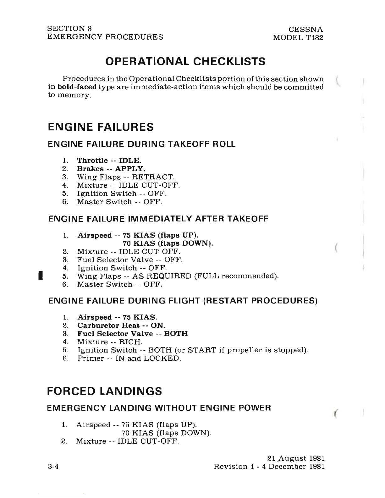
OPERATIONAL
CHECKLISTS
Procedures
in
the
Operational
Checklists
portion
of
this
section
shown
l
in
bold-faced
type
are
immediate-action
items
which
should
be
committed
to
memory.
ENGINE
FAILURES
ENGINE
FAILURE
DURING
TAKEOFF
ROLL
1.
Throttle --IDLE.
2.
Brakes
--
APPLY.
3.
Wing
Flaps --RETRACT.
4.
Mixture
--
IDLE
CUT-OFF.
5.
Ignition
Switch --OFF.
6.
Master
Switch --OFF.
ENGINE
FAILURE
IMMEDIATELY
AFTER TAKEOFF
1.
Airspeed
--
75
KIAS
(flaps
UP).
70
KIAS
(flaps
DOWN).
2.
Mixture --IDLE
CUT-OFF.
3.
Fuel
Selector
Valve --OFF.
4.
Ignition
Switch --OFF.
I
5.
Wing
Flaps --AS
REQUIRED
(FULL
recommended).
6.
Master
Switch --OFF.
ENGINE
FAILURE
DURING
FLIGHT
(RESTART
PROCEDURES)
1.
Airspeed
--
75
KIAS.
2.
Carburetor
Heat --ON.
3.
Fuel
Selector
Valve --BOTH
4.
Mixture --RICH.
5.
Ignition
Switch --BOTH
(or
START
if
propeller
is
stopped).
6.
Primer --IN
and
LOCKED.
FORCED
LANDINGS
EMERGENCY
LANDING
WITHOUT
ENGINE
POWER
1.
Airspeed
-- 75
KIAS
(flaps
UP).
70
KIAS
(flaps
DOWN).
2.
Mixture --IDLE
CUT-OFF.
21
,August
1981
3-4
Revision
1 - 4
December
1981
 Loading...