

Cessna SKYMASTER 336 1964 Service Manual

REVISION
MODEL
336
SKYMASTER
1964
SERVICE
D238C2-13
INSERT
PAGES
MANUAL
CHANGE
5
JANUARY
THE
INTO
FOLLOWING
THE
2
2004
BASIC
CHANGED
MANUAL

Cessna
A
Textron
Company
Service
Manual
MODEL
1964
336
FAA
APPROVAL
CHANGE
TEMPORARY
TEMPORARY REVISION 4 DATED
COPYRIGHT © 2004
CESSNA
AIRCRAFT
WICHITA,
D238-2-13
KANSAS,
HAS
BEEN
2
TO THE
CHANGE 2 DATED
COMPANY
USA
OBTAINED
BASIC
ON
MANUAL
23
TECHNICAL
INCORPORATES
MARCH 1978,
17
MARCH 1995.
DATA
Change
IN
THIS
PUBLICATION
TEMPORARY
TEMPORARY
2
SKYMASTER
THAT
AFFECTS AIRPLANE
CHANGE 1 DATED
CHANGE 3 DATED
Member
27 FEBRUARY
1
DECEMBER 1980,
1
APRIL
5
JANUARY
TYPE
DESIGN
of GAMA
1978,
AND
1964
2004
CESSNA
SERVICE
AIRCRAFT
MODEL
336
MANUAL
COMPANY
Dates
of
issue
for
original
Original
Change.............1
Change
Page
No.
Title
A
........................................
i
thru
iv
(Blank)
1-1
thru
2-1
thru
2-5
thru
2-11
thru
2-13
thru
2-15
thru
3-1
thru
4-1
thru
5-1
thru
5 -9
......................................
5-10
thru
6-1
thru
7-1
thru
..........
............
.
.......................
vi
...............................
............................
1-3
.......................
2-4
.......................
2-10
2-12
2-14 ...................
2-22
3-18 .....................
4-7
.......................
5-8
.......................
5-20
6-7
........................
7-8
.......................
0.............
2.............5
.....................
....................
.................
....................
and
.............
Change
No.
2*
2
2*
2*
0
0
1
2*
0
2*
0
0
0
1
0
0
0
changed
1
April
15
June
January
*
LIST
OF
EFFECTIVE
pages
are:
1964
1964
2004
Page
No.
8-1
thru
8-6
........................
8-7 thru
9-1
9 -3
9-4
10
10
10-3
10-18..................................1
10-19thru
10-33..................................1
10-34
10-47
11-1
11-3
11-17
12-1
8-14
......................
thru
9-2
.......................
.....................................
thru
9-9
........................
-1
...................................
-2
...................................
thru
10-17
..................
10-32
................
thru
10-46
................
thru
10-48
................
thru
11-2
....................
thru
11-16
..................
thru
11-18
...............
thru
12-3
....................
PAGES
Change
No.
0
2*
0
1
0
0
1
0
0
0
0
2*
0
2*
0
Page
No.
12
-4
....................................
12-5
thru
12-8
1 3 -1
....................................
13
-2
....................................
13-3
thru
13-11
14-1
thru
14-16
14-17thru
14-19
14-21
15-1
16-1
17-1
18-1
Drawing
Pages
14-18 ...............
thru
14-20
thru
14-23
thru
15-12
thru
16-6
thru
17-2
....................................
1470000
1
thru
Change
No.
....................
..................
..................
................
............
..................
....................
....................
16.3...............0
1
0
1
0
1
0
2*
0
2*
0
0
0
0
I
NOTE: Insert
NOTE:
Change
Jun
2
5/2004
*
Indicates
latest
changed
pages
pages. Destroy
changed,
added,
superseded
or
deleted
©
Cessna
by
Aircraft
pages.
the
current
Company
change.
I
A

CESSNA
SERVICE
AIRCRAFT
MODEL
336
MANUAL
COMPANY
SECTION
1
GENERAL DESCRIPTION
2
SERVICING
3
FUSELAGE
4
WINGS,
5
LANDING
6
AILERON
7
FLAP
8
ELEVATOR, TRIM
9
RUDDER
POW
10
11
12
ERPLANTS
FUEL
PROPELLERS
CONTROL
............................................................
.............................................................
BOOMS, AND
GEAR
CONTROL
CONTROL
SYSTEM
................................................ 1-1
EMPENNAGE
........................................................
SYSTEM
SYSTEM
AND
.........................................................
..........................................................
..........................................................
...............................................
INTERCONNECT
SYSTEM
.....................
......................................
.......................................
CONTROL
SYSTEMS
........................
.............
TABLE
OF
.....
CONTENTS
PAGE
2-1
3-1
4-1
5-1
6-1
7-1
8-1
9-1
10-1
11-1
12-1
13
UTILITY
14
INSTRUMENTS
15
ELECTRICAL
16
STRUCTURAL
17
PAINTING
18
WIRING
SYSTEMS
...............................................................
DIAGRAMS
.......................................................
.........................................................
SYSTEMS
REPAIR
..................................................
...................................................
.....................................................
13-1
14-1
15-1
16-1
17-1
18-1
Change
Jan
5/2004
2
©
Cessna
Aircraft
Company
CESSNA
SERVICE
AIRCRAFT
MODEL
MANUAL
COMPANY
336
All
aircraft,
names
model
the
same
number.
regardless
are
used
numbers
basic
POPULAR
of
manufacturer,
for
marketing
will
be used
model.
SKYMASTER
The
NAME
CROSS-REFERENCE
NAME
in
following
VS.
MODEL
are
purposes.
this publication
To provide
table provides
certified
unless
MODEL
YEAR
1964
1964
1964
LISTING
NUMBER
under
a
consistent
names
a
cross-reference
MODEL
OF
AND
model
are
336
336
336
POPULAR
SERIALS
number
method
required
BEGINNING
SERIAL
NUMBER
336-0001
designations.
of
referring
to
differentiate
listing
of
to the
between
popular
ENDING
SERIAL
NUMBER
336-0195
However,
various
versions
name
vs.
633
636
popular
aircraft,
of
model
ii
©
Cessna
Aircraft
Company
Change
Jan 5/2004
2

1.
GENERAL.
CESSNA
SERVICE
AIRCRAFT
MODEL
336
MANUAL
COMPANY
WARNING:
A.
The
information
supplemented,
Information
Changes,
amendments
through
also
have
parts
breakdowns
supplemented,
be
reissued
and
are
subscription
ALL
INSPECTION
METHODS
CESSNA
OVERHAULED
MANUFACTURED,
ENTITIES
MAINTENANCE/SERVICE
APPLICABLE
NON-CESSNA
OVERHAUL
FOR
AND/OR
Letters,
Revisions,
to
the
Cessna
been
by
communicated
services.
OF
ARE
OTHER
SUCH
NON-CESSNA
SELLER
in
this publication
and
automatically
Service
Reissues
this
publication
Propeller
supplied
for some
and
specifically
Cessna.
INTERVALS,
INSPECTION,
SOLELY
CESSNA-APPROVED
REMANUFACTURED,
THAN
AND THE
PARTS.
TIME
LIMITS,
OF SUCH
Bulletins,
and
through
Aircraft
with a group
of
the
amended
Supplier publications
to
the
field
REPLACEMENT
LIFE
LIMITS,
BASED
CESSNA,
PURCHASER
ALL
is
amended
Temporary
various
through Cessna's
ON
THE
THEN
MANUALS
INSPECTION
METHOD
PARTS
NON-CESSNA
based
Service
information
Product
of
supplier
OF
MUST
on
data
by
all
Newsletters,
Revisions.
Support subscription
supplier
by
supplier-issued
reissued
AND
CYCLE
USE
OF
PARTS.
IS
information
publications
equipment
IF
OVERHAULED,
THE
DATA
PARTS
WARNED
INTERVALS,
INSPECTION,
BE
OBTAINED
PARTS.
available
Supplier
Users
available
by
Cessna
Authorized
TIME
LIMITS,
LIMITS,
NEW,
REMANUFACTURED,
PARTS
at
issued
at
which
items.
revisions
ARE DESIGNED,
IN
CESSNA'S
CATALOGS
NOT
TO
REPLACEMENT
LIFE
FROM THE
the
time
in
Service
are
urged
Cessna
services.
provide
Supplier's publications
automatically
Service
OVERHAUL
ETC.,
RECOMMENDED
AND/OR
RELY
LIMITS,
of
Service
Authorized
and
Stations
APPROVED
ARE
NO
LONGER
ON
SUCH
CYCLE
MANUFACTURER
publication
Letters,
Notices,
to
keep
Cessna
disassembly, overhaul,
service
Publication
abreast
Service
information
amend
and/or
TIME
LIMITS,
OR
BY
DATA
TIME
LIMITS,
LIMITS,
and
is
updated,
Service
of
the
Stations
Service
Stations
are
updated,
which
this publication
through
BY
FOR
ETC.,
latest
or
and
may
Cessna's
B.
Inspection,
When
installation
STC.
stresses
airplanes
C.
REVISIONS,
Station or
D.
Information
following
E.
All
Stations
Therefore,
Service
maintenance,
an
STC
installation
must
STC
installations
on
adjacent
with STC
REISSUES
directly
Cessna
Department
P.O. Box
Wichita,
supplemental
Aircraft
7706
Kansas
in
this
range
so
that
it
is
Organization.
and
is
incorporated
be
inspected
can
change
structures
installations.
and
from
Cessna Aircraft
Company
751C
67277-7706
Service
of
serial
numbers;
service
they
recommended
information
have
the latest
parts
requirements
in
accordance
systems
of
the
airplane.
TEMPORARY
Company
Manual
is
applicable
336-0001
concerning
authoritative recommendations
that
Cessna
on
the
airplane,
with
interface,
Cessna
REVISIONS
thru
336-0195,
this
owners
for
STC
installations
those
the
inspection
operating
provided
can be
at the
following address:
to
all
U.S.
manual
utilize
the
portions
program
characteristics
inspection
purchased
Certified
633
and
636.
is
supplied
for
knowledge
are
not
of
the
published
criteria may
from
Model
to
all
servicing
and
included
airplane
and
appropriate
experience
in
this
manual.
affected
by
the
component
not
a
Cessna Service
336
airplanes
these Cessna airplanes.
by
owner
loads
be
valid
within
Cessna
of
the Cessna
of
the
the
or
for
the
Service
Change
Jan
5/2004
2
©
Cessna
Aircraft
Company
iii
2.
CROSS-REFERENCE
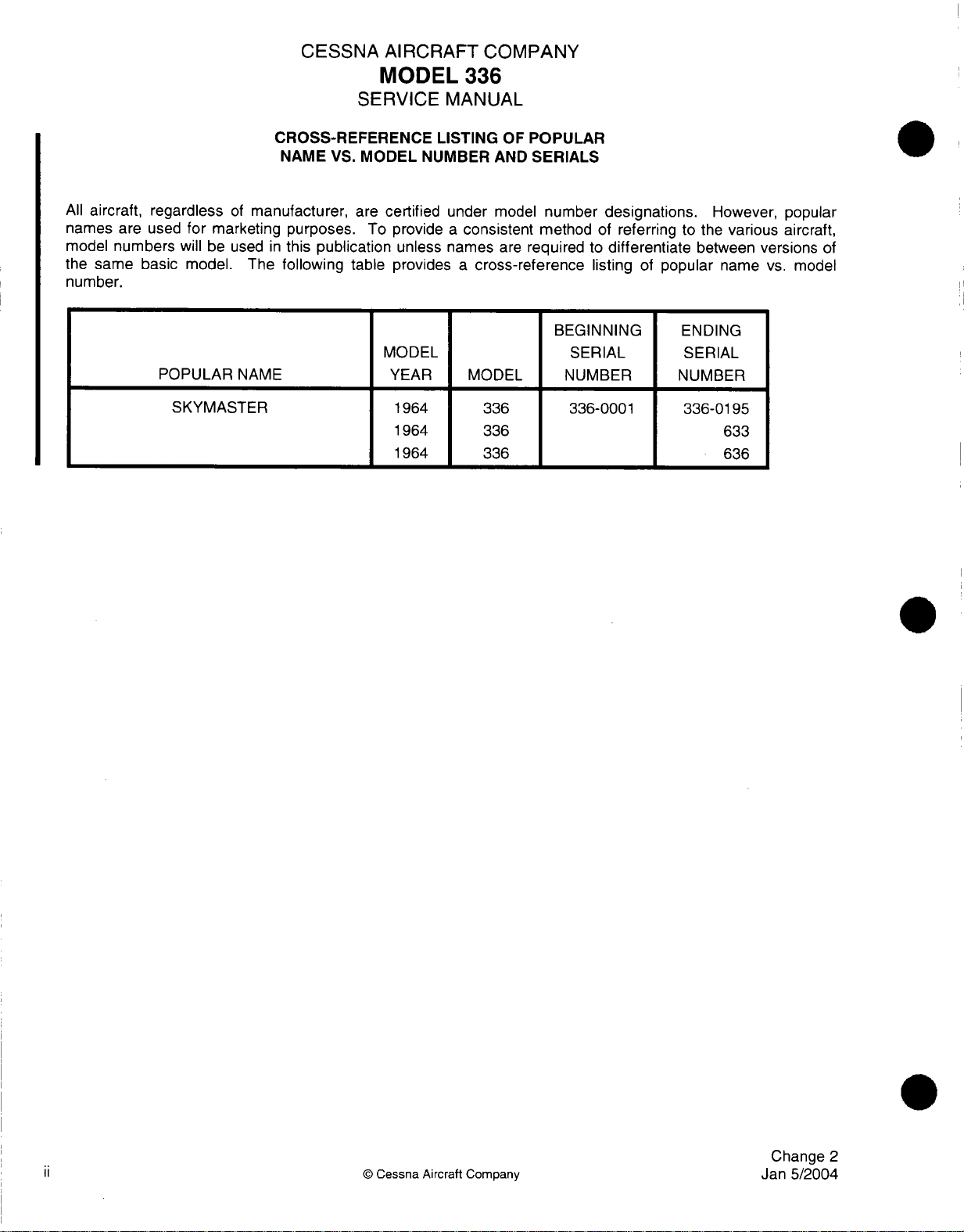
A.
All
airplanes, regardless
popular
these airplanes,
to
popular
B.
The
personnel
information
components
C.
Technical
this
systems,
4.
TEMPORARY
A.
Additional
used
operations.
incorporated
names
differentiate
name, model
Cessna
in
Publications
manual.
and
REVISIONS.
information,
to
provide,
LISTING
are
often
the
model
between
Skymaster
servicing
required
or
These
Temporary
into the
repair
may
to
be
without
CESSNA
OF
POPULAR
of
manufacturer,
used
for marketing
number
versions
number,
Series
and
enable
systems.
are
manuals
purchased
which
revisions
maintenance
of the
and
(1964)
maintaining
the
also
available
must
becomes
delay,
AIRCRAFT
MODEL
SERVICE
will be
same
serial
numbers.
Service
Model
mechanic
be
utilized
from
the
available,
new
information,
are
manual
COMPANY
336
MANUAL
NAME
are
used
for
manufacturer.
numbered
at
VERSUS
certified
purposes. To provide
basic
Manual
336
to
service,
the
the
under
in
this
publication
model.
has
airplanes.
various
as
required
may
be
which will
consecutively.
next
revision.
inspect,
components
MODEL
model
unless
The
table
been
prepared
This
manual
troubleshoot,
for
maintenance
provided
assist
NUMBER
number
a
consistent
the
on
page
and
by
temporary
in
Temporary
AND
SERIALS.
designations.
method
popular
ii
provides
to
assist
provides
remove, and
systems
of
maintaining safe
of
name
a
maintenance
the
necessary
that
are
those components
revision. This
revisions
However,
referring
is
necessary
listing
of
replace
not
covered
service
flight/ground
are
to
in
and
is
normally
5.
SERIALIZATION.
A.
All
airplanes
remains
Airplane
of a serial
6.
REVISION FILING
A.
Regular Revision.
(1)
Pages
located
The
number
most recent
Effectivity
NOTE:
B.
Temporary
(1)
File
the
are
issued a serial
with
the
airplane
serial numbers
number
to
at the
first
Beginning
Revision.
temporary
first
in
INSTRUCTIONS.
be
removed
front
number(s)
for
that
section.
date
page
must
pages.
page.
page
Revisions
revisions
of
the
throughout
are
text
or
or
of
this
which
of
page
verify
with
Change 2 to
temporary
number.
used
to
illustration indicates
inserted
manual.
represent
When
two
issue
must
the
active
prior
to
in
the
applicable
revision.
This number
its
service
identify
in
changes
the
maintenance manual
Page
numbers
the
manual
pages
be
inserted
page.
this
service
Change 2 do
section
life.
This serial
within
the
material
are
section
display
the
in
the
manual, a date
not
in
is
assigned
the text
is
listed
number
same two-element
service
have
a
accordance
as
number
or within
applicable
are
determined
in
sequence
are
manual.
will
date
printed
with
airplane
appears
followed
appear
filing
on
an
to
all
airplanes.
by
by a two-element
number,
The
date
on
at
the bottom
instructions
construction
the
airplane
illustration.
the
effectivity
by a dash
the bottom
the
page
column
of
appearing
then
the
begins
data
The
number.
the
with
on
the
of
all
revised
and
plate.
absence
page
A
page
the
revised
on
iv
(2)
The
rescission
or
by a superseding
of a temporary
temporary
revision
revision.
©
Cessna
is
accomplished
Aircraft
Company
by
incorporation
into
the
maintenance
manual
Change
Jan
5/2004
2
7.
IDENTIFYING
A.
Additions
of
B.
When technical
placed
page.
C.
When
revision
D.
For
directing
E.
Changes
the
page
These
extensive
revised
REVISED
or
revisions
and
in
the
pages
bars
or
attention
to wiring
adjacent
changes
outside
technical
will
appear
new
illustrations,
to
diagrams
MATERIAL.
to
text
to
the change.
cause
margin
will
display
changes
the
the
area
CESSNA
SERVICE
in
an
existing
unchanged
adjacent
full
will
are
the
current
are
length
either
indicate
indicated
to
AIRCRAFT
MODEL
section
text
to
the
page
revision
made
to
text
of
text.
a
revision
new
or
by
shaded
COMPANY
336
MANUAL
will
be
appear
number,
date
in
in
an
bar along
revised
areas.
identified
on
a
different
providing
the inside
existing
the
information.
side
section
of
by
a
page(s),
no
other
margin
the
revision
revision
opposite
that
requires
page
or a hand
bar
in
a
revision
of
the
outside
bar
bar
appears
the
page
extensive
indicator
margin
will
be
on
number.
revision,
the
NOTE:
8.
WARNINGS,
A.
Throughout
accomplished
Warnings
WARNING:
CAUTION:
NOTE:
9.
PROPELLER
A. A Cessna
Service
Beginning
revised
Cessna
Department
P.O.
Wichita,
page.
CAUTIONS
the
and
AIRCRAFT
Propeller
Station
Aircraft
Box
7706
Kansas
with
Change
Revisions
text
in
are
utilized.
Cautions
Calls
attention
which
must
Calls
attention
the
airplane
Calls
attention
Aircraft
or
directly
Company
751
C
67277-7706
2
to
this
prior
AND
NOTES.
this manual,
These
precede
be
CUSTOMER
from
adjuncts
the
to
use
followed
to
methods
or
equipment.
to
methods that
Customer
Cessna
service
to
Change
warnings,
text
they
of
materials,
precisely
and
CARE
Care
Aircraft
manual,
2
do
not
cautions
to
the
text
pertain
processes,
to
avoid
procedures
will
make
SUPPLIES
Supplies
Company.
a
revision
have
and
notes
are used
to,
and
injury or
which
the
job
AND
PUBLICATIONS
and
Publications
The
bar
will
a
revision bar
pertaining
to
highlight
Notes
follow
methods,
death
must
easier.
address
appear
procedures,
be
Catalog
to
indicate
to
or
emphasize
the text
to
personnel.
followed
CATALOG.
is:
on
the
the
outside
revised
procedures
they
or
limits
to
avoid
is
available
margin
information.
important
pertain
damage
from
being
to.
a
of the
points.
to
Cessna
10.
CUSTOMER
A.
Change
Jan
5/2004
This
catalog
models
issued
Cessna
This
manual
to
report
wish
to
2
lists
as
well
as
in
paper
and
COMMENTS.
Aircraft
make.
any
Company
can
errors,
all
publications
new
products.
aerofiche
has
be
improved
discrepancies,
and
To
maintain
form.
endeavored
with
your
and
©
Cessna
Customer
this
to
furnish
help.
Please
omissions
Aircraft
Care
catalog
you with
use
in
this
Company
Supplies
in a current
an
the
return
manual
available
accurate,
card
that
as
well
from
status,
useful
is
provided
as
any
Cessna
it
is
revised
and
up-to-date
general
for
prior
yearly
with
your
comments
year
and
manual.
manual
you
v
CESSNA
SERVICE
AIRCRAFT
MODEL
336
MANUAL
COMPANY
I
(THIS
PAGE
INTENTIONALLY
LEFT
BLANK)
Change
©
vi
Cessna
Aircraft
Company
Jan
2
5/2004
SECTION
1
1-1.
GENERAL
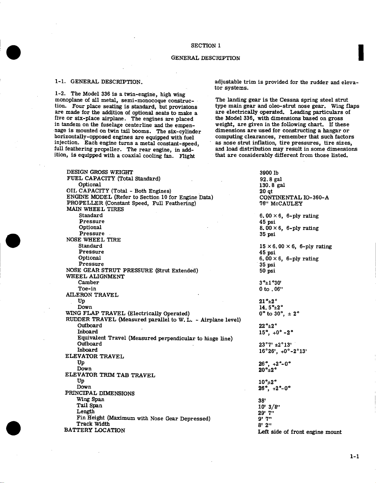
1-2.
The
monoplane
tion.
Four
are
made
five
or
six-place
in
tandem
nage
is
mounted
for
Model
of
all
place
the
on
the
DESCRIPTION.
336
metal,
seating
addition
airplane.
fuselage
on
horizontally-opposed
injection.
full
feathering
ition,
Each
is
equipped
DESIGN
FUEL
CAPACITY
engine
propeller.
GROSS
Optional
OIL
CAPACITY
ENGINE
MODEL
PROPELLER
MAIN
WHEEL
Standard
Pressure
Optional
Pressure
NOSE
WHEEL TIRE
Standard
Pressure
Optional
Pressure
NOSE
GEAR
STRUT PRESSURE
WHEEL
ALIGNMENT
Camber
Toe-in
AILERON
TRAVEL
Up
Down
WING
FLAP
RUDDER
TRAVEL
TRAVEL
Outboard
Inboard
Equivalent
Outboard
Inboard
ELEVATOR
Up
TRAVEL
Down
ELEVATOR
Up
TRIM
Down
PRINCIPAL
Wing
Tail
DIMENSIONS
Span
Span
Length
Fin
Height
Track
Width
BATTERY
LOCATION
is
a
twin-engine,
semi-monocoque
is
of
centerline
twin
tail
engines
turns a metal
with
a coaxial
WEIGHT
(Total
(Total -Both
(Refer
(Constant
TIRES
(Measured
Travel
TAB
(Maximum
standard,
optional
The
engines
booms.
are
equipped
The
rear
cooling
Standard)
Engines)
to
Section
Speed,
(Electrically
parallel
(Measured
TRAVEL
with
GENERAL
high
wing
construc-
but
provisions
seats
to
make
are
placed
and
the
empen-
The
six-cylinder
with
fuel
constant-speed,
engine,
Full
in
fan.
Flight
10
for
Engine Data)
Feathering)
add-
(Strut Extended)
Operated)
to
W.
perpendicular
Nose
Gear
Depressed)
DESCRIPTION
a
L. -
Airplane
to
hinge
adjustable
tor
systems.
The
landing
type
main
are
electrically
the
Model
weight,
are
dimensions
computing
as
nose
and
load
that
are
level)
line)
trim
is
provided
gear
is
gear
and
operated.
336,
with
given
in
are
used
clearances,
strut
inflation,
distribution
considerably
3900
92.8
130.8
20 qt
CONTINENTAL
76"
6.00 x 6,
45
8.
35
15 x 6.00 x 6,
45
6.
35
50
3°±1°30'
0
to .06"
21
14.
°
0
220±2"
15°,
23°7'
16°26',
26°,
20°±20
10°*20
26°,
38'
10'
29'
9'
8'
Left
for
the
the
Cessna
oleo-strut
spring
nose
Leading
dimensions
the
following
for
constructing a hangar
based
remember
tire
pressures,
may
result
different
from
lb
gal
gal
McCAULEY
6-ply
rating
psi
00 x 6,
6-ply
psi
6-ply
psi
00 x 6,
6-ply
psi
psi
±2°
50±2
to
30°,
±
2"
+0
-2°
+2013'
+0°-2°13'
0
+2
-00
+2'_-0
3/8"
7"
7"
2"
side
of
front
rudder
gear.
chart.
and
steel
Wing
particulars
on
gross
If
these
eleva-
strut
flaps
of
or
that
such
factors
tire
sizes,
in some dimensions
those
listed.
IO-360-A
rating
rating
rating
engine
mount
1-1

WING
STATIONS
222.00
,
192.00
34.45
0 342.30
27.25
162.00
0
7
60.
135.60
I
107.60
110.50
79.60
138.75
55.50
-e
42.75
AIRPLANE
-30.
00
23.00
19.85
51.50
STA.
70.
00
AT £ OF
1 1
BOOM
TO
FUSELAGE STA.
FUSELAGE
120.00
I
.
I!
I
CORRESPONDS
193.90
STATIONS
_
_
1-2
Figure
1-1.
Reference
Stations
BOLT
(See
SIZE
Note
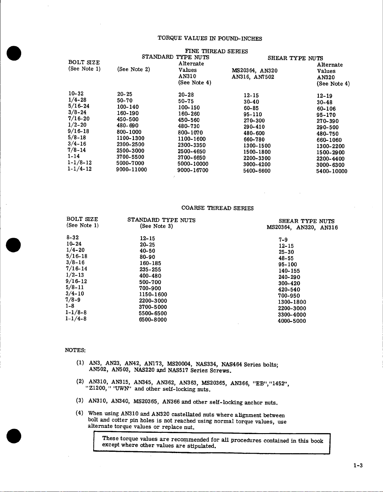
TORQUE VALUES
FINE
STANDARD
(See
Note
e
1)
2)
TYPE
Alternate
Values
AN310
(See
THREAD
NUTS
Note
IN
POUND-INCHES
SERIES
4)
MS203
AN316
64,
,
AN7502
SHEAR
AN320
TYPE
NUTS
Alternate
Values
AN320
(See
Note
4)
10-32
1/4-28
5/16-24
3/8-24
7/16-20
1/2-20
9/16-18
5/8-18
3/4-16
7/8-14
1-14
1-1/8-12
1-1/4-12
BOLT
(See
Note
8-32
10-24
1/4-20
5/16-18
3/8-16
7/16-14
1/2-13
9/16-12
5/8-11
3/4-10
7/8-9
1-8
1-1/8-8
1-1/4-8
SIZE
TYPE
AN320,
12-19
30-48
60-106
95-170
270-390
290-500
480-750
660-1060
1300-2200
1500-2900
2200-4400
3000-6300
5400-10000
NUTS
AN316
20-25
50-70
100-140
160-190
450-500
480-690
800-1000
1100-1300
2300-2500
2500-3000
3700-5500
5000-7000
9000-11000
STANDARD
1)
Note
(See
12-15
20-25
40-50
80-90
160-185
235-255
400-480
500-700
700-900
1150-1600
2200-3000
3700-5000
5500-6500
6500-8000
TYPE
3)
20-28
50-75
100-150
160-260
450-560
480-730
800-1070
1100-1600
2300-3350
2500-4650
3700-6650
5000-10000
9000-16700
COARSE
NUTS
THREAD
12-15
30-40
60-85
95-110
270-300
290-410
480-600
660-780
1300-1500
1500-1800
2200-3300
3000-4200
5400-6600
SERIES
SHEAR
MS20364,
7-9
12-15
25-30
48-55
95-100
140-155
240-290
300-420
420-540
700-950
1300-1800
2200-3000
3300-4000
4000-5000
NOTES:
(1)
(2)
(3)
(4)
AN3,
AN23,
AN502,
AN310,
"Z1200, " "UWN"
AN310,
When
using
bolt
and
alternate
These
except
AN42,
AN503,
AN315,
AN340,
AN310
cotter
torque
torque
where
AN173,
NAS220
AN345,
and
other self-locking
MS20365,
and
AN320
pin
holes
values
values
other
and
AN362,
AN366
is
not
or
replace
are
values
MS20004,
NAS517
AN363,
and
castellated
reached using
nut.
recommended
are
stipulated.
NAS334,
Series
MS20365,
nuts.
other
Screws.
self-locking
nuts
where
normal
for
NAS464
AN366,
alignment
torque values,
all
procedures
Series bolts;
"EB","1452",
anchor nuts.
between
contained
use
in
this
book
1-3

TABLE
OF
CONTENTS
GROUND
HANDLING,
SECTION
SERVICING,
Page
2
LUBRICATION,
AND
INSPECTION
I
GROUND
Hangar Storage
Leveling
SERVICING
Fuel
Engine
Engine
Battery
2-1.
2-2.
complished
struts
gear
plane.
ment
2-3.
means
equipment.
336-0058
tional
spars
optional
length
prevent
If
desired, a spreader
vertical
plane
2-4.
wheel
weighted
point is
tered
HANDLING
Towing
Hoisting
Jacking
Parking
Tie-Down
Outside
Extended
Returning
Fuel
When
wheel
center
not
surfaces.
.........
.........
Storage
Tanks ...............
Drains
Oil
Induction
.
GROUND
TOWING.
by
as
push
is
used
The
two
and
is
stowed
towing
more
or
push
HOISTING.
of
hoisting
and on,
hoisting
are
provided
hoisting
of
60
inches
bending
force
use a hoist
JACKING.
of
clear
down
provided
behind
........
........
........
Storage
Airplane
........
........
using
points.
for
the
on
Beginning with
rings
to
the
or
the
............
.............
.............
............
to
Service
... ..........
...............
Air
Filters
HANDLING.
Moving
steering
bar
the
than
nose
control surfaces
provisions
rings
of
the
of
(See
tied
on
nose
the
airplane
the
wing
A
tow
and
is
provided
in
the
baggage
CAUTION
airplane,
39
degrees
gear
will
The
airplane
lugs
which
are
airplane
for
to
the
as
for
the
a
ground,
front
standard
used, a minimum
are
each
cable
eyebolt
jig
may
eyebolts.
minimum
figure
2-1.)
the
down. A permanent
the
bottom
gear,
so
.......
.......
by
struts
or
bar
maneuvering
as
never
either
be
may
equipment.
type
be
When
capacity
tail
of
the
landing
attached
standard
compartment.
turn
side
damaged.
or
empennage
be
lifted
provided
serial
attaching
and
rear
is
required
hoisting
fabricated
hoisting
raise
To
may
be
the
fuselage,
nose
gear
hand
is
to
the
the
equip-
the
nose
of
Do
by
as
optional
number
the
op-
carry-thru
If
cable
to
rings.
to
the
three
of
the
carefully
jack
may
ac-
gear
nose
air-
the
apply
air-
tons.
nose
cen-
2-1
2-1
2-1
2-1
2-4
2-4
2-4
2-4
2-4
2-4
2-5
2-5
2-5
2-5
2-5
2-5
2-5
be
Tires
Nose
Nose
Hydraulic
Oxygen
Oxygen
CLEANING
Windshields
Plastic
Aluminum
Painted
Engine
Upholstery
Propellers
LUBRICATION
INSPECTION
jacked
an
optional
gear
casting
When
ity
to
the
a
wheels
points
To
jack
points.
the
of
front
in
the
screw
sure
after
airplane
the
jack
moving
on
the
be
weighted
used
are
under
is
worked
jacks
and
210
wing
slightly
. .. ...... .
Gear
Gear
Cylinder
Face
Trim
Surfaces
Compartment
if desired.
universal
spring
wing
to
jacking
points
jack
should
jacking
as
a
using
the
of
inboard
slide
jack.
second
and
jacking
simultaneously
is
both
main
These
strut,
wing
spar.
nutplate-provided
install
and
remove
must
are
the
front
engine
when
simultaneously.
tail
the
on
adapter
310
jack
points.
gain
to
Strut
.......
Shimmy
Brake
Systems
.......
Masks
.....
and
Windows
........
Surfaces
and
Interior
....
.....
.....
To
be
point.
.CAUTION
the universal
strut
gear
as
jack
The
operation.
not
recommended.
gears at
points
jack
in
the
A
countersunk
jack
points
jack
operation
be
weighted
used.
engine
engine
and
all
three
the
stand,
should
The
initial
to
jacked
booms
in
Dampener
.....
.....
......
....
jack
one main
jack
point
used.
cause
will
the
wheel
must
with
once
are
bottom
the
for
points
and
is
completed.
is
This
cowl and
mount.
jack
Stands
steady
position.
or
the
be
utilized
may
tail
clearance
.
. .
. .
. . .
gear
which
attaches
Do
not
use
jack
point,
the
main
is
raised,
then
in
accomplished
lowered
be
Jacking
universal
the
use
installed
forward
screw
points.
jack
the
nutplates.
reinstall
The
anytime
down
placing
The
nose
points,
should
airplane
the
The
combination
when
to
have
for
the
is
nose,
at
the
flexibil-
tilting
both
jack
wing
just
flange
installed
screws
nose
by
shot
must
be
placed
before
Model
using
be
lowered
jacks.
2-14
a
time,
to
brake
wheel
for
jack
outboard
of
the
Remove
Be
of
wing
the
re-
bags
also
wing,
and
310
Models
the
2-6
2-6
2-6
2-6
2-6
2-7
2-7
2-7
2-7
2-7
2-7
2-7
2-7
2-7
2-7
the
it
2-1
Spare
310
rars
jack
iuepartmeni).
also
is
available.
A
comui
Jack
(Model
310)
2-2
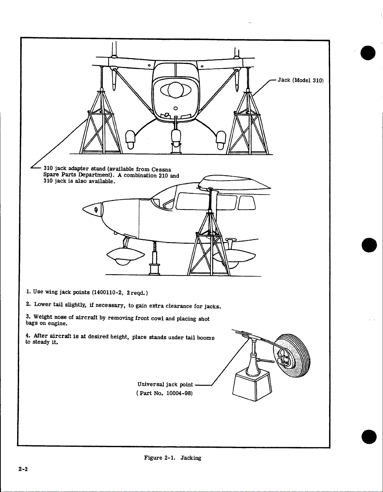
1.
Use
2.
3.
Weight
bags
4.
to
steady
wing
Lower
on
After
jack
tail
nose
engine.
aircraft
it.
points
slightly,
of
aircraft
is
at
(1400110-2,
if
necessary,
by
removing
desired
2
reqd.)
to
gain
front
height, place
Universal
(Part
extra
cowl
stands
No.
Figure
clearance
and
placing
under
jack
point
10004-98)
Jacking
2-1.
tail
for
jacks.
shot
CHAIN,
CABLE,
OR
ROPE
CHAIN,
ROPE
DO
TO
CABLE,
ONL
NOT
TORQUE
TIE
OR
ROPE
ROPE
CONTROL
CHAIN,
CABLE,
OR
ROPE
Figure
2-2.
Tie-Down
Diagram
2-3
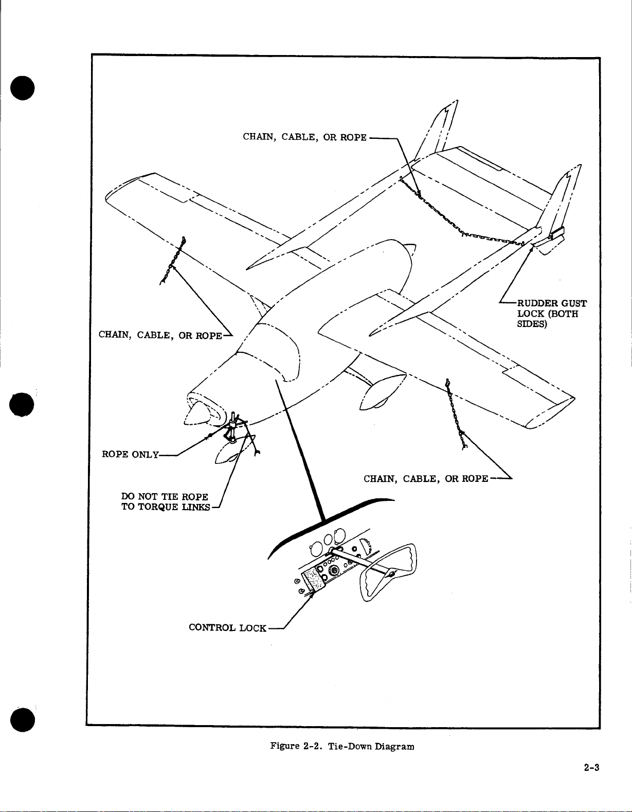
2-5.
PARKING.
pally
on
it
is
wise
and
install
high
wind
lined
in
paragraph
2-6.
TIE-DOWN
pation
of
left
outside
tie
down
a.
Set
b.
Install
and
rudder
c.
Secure
tensile
fasten
tensile
and
d.
strength
to
Secure
strength
fasten
anchor.
e.
Tie the
cable)
to
Pull
each
fittings.
f.
Install
2-7.
HANGAR
hangar
requires
ations-will
condition;
local
conditions.
to
set
the
control
conditions,
high
winds.
for
as
follows:
parking
a
surface
as
shown
chains
ground
chains
each
middle
the
nose
end
away
pitot
STORAGE.
maintain
Parking
the
parking
2-6
should
lengthy
brake
in
or ropes
to
tie-down
anchors.
or
to
tie-down
rope
or
of a rope
gear
45
tube
little
the
precautions
As a general
brake
lock.
tie
down
if
a
hangar
be
accomplished
Anytime
periods,
and
install
control
figure
of
fittings
ropes
of
fitting
chain
mounting
degrees
cover.
An
attention.
airplane
depend
or
chock
In
severe
the
airplane as
is
not
the
airplane
such
as
control
lock
between
2-2.
700
pounds
under
700
pounds
on
each
to a common
(do
not
use a chain
(see
figure
and
secure
airplane
The
following
in a serviceable
princi-
precaution,
the
weather,
out-
available.
in
anticiis
overnight,
wheel
each
or
more
wings
or
more
tail
ground
2-2).
to
ground
stored
wheels
and
to
be
lock.
fin
and
boom
or
in
a
oper-
Monitor
Temperature
lowable.
d.
With
moved,
duction
minute,
then
spray
airbox,
until
increase
Injecting
lock.
e.
Do
f.
preventive
180°F.,
g.
and
not
Remove
into
Replace
install
holes.
h.
Cover
or other
and
suitable
accessory
vapor-proof
i.
Drain
gine
sump
CAUTION
cylinder
engine
smoke
head
temperature
shall
not
operating
corrosion-preventive
at
the
rate
comes
the
spray until
CAUTION
oil
too
fast
can
rotate
propeller
all
spark
plugs,
oil,
which
has
been
all
spark
plug
lower
spark
dehydrator
spark
plug
covers,
vents,
covering
corrosion-preventive
and
re-install
plugs
plugs
terminals
and
and
other
material.
drain
exceed
and
induction
of
one-half
from
the
cause
after
and
pre-heated
holes.
or
in
the
cover
openings
plugs.
closely.
maximum
oil
into
gallon
the
exhaust
engine
is
a
hydrostatic
completing
spray
install
upper
with
shipping
all
other
oil
from
al-
air
filter
the
in-
per
stack,
stopped.
step
corrosion-
to
150°
solid
plugs,
spark
plug
plugs
engine
with
a
each en-
re-
d.
-
If
the
period,
a.
Make
tate
propeller
oil
film
b.
sation
c.
trolyte
2-8.
storage
on
Keep
in
Keep
from
OUTSIDE
of
procedures
well
as
the
addition,
engine
cowl,
protective
blowing
2-9.
dust
EXTENDED
precautions
the
airplane
a.
Operate
normal
and
re-install
b.
range.
Fill
corrosion
to
225°.
mends
&
five
Co.,
c.
Cosmoline
305
Start
minutes.
airplane
see
paragraph
sure
all
by
hand
the
internal
fuel
tanks
the
tanks.
battery
fully
freezing
STORAGE.
an
airplane
in
accordance
precautions
the
pitot
and
other
covers
are
in
addition
in
a hangar.
installed
anticipated.
engines
Drain
drain
each
engine
preventive
Continental
No.
W.
Lehigh
and
operate
NOTE
is
to
be
stored
2-9.
switches
every
parts
full
to
charged
in
an
unheated
requires
with
listed
tube,
air
similar
if
STORAGE
to
secure
until
oil
engine
plugs.
oil
sump
oil,
which
Motors
1223
supplied
Avenue,
engines
for
are
turned
few
days to
of
the
retard
moisture
to
prevent
Short-term
secure
paragraph
in
paragraph
vents,
openings
openings
rain,
requires
tie-down
temperature
oil
sumps
with
has
Corporation
Philadelphia,
at
1200-1500
a
long
off,
engine.
hangar.
tie-down
sleet,
the
completely
10
quarts
been
by
E.
then
maintain
conden-
the
elec-
outside
2-6,
as
2-7.
in
the
should
snow,
following
or
storing
reaches
of
pre-heated
recom-
F.
Houghton
Penn.
rpm
ro-
In
have
or
for
an
The
paint
faces
j.
Attach
knobs,
ricating
that
it
should
storage.
k.
Lubricate
all
openings.
1.
Remove
cool
place;
m.
Block
to
prevent
Tires
of-round,
than a few
airplane
tires
2-10.
a
vice
flight
RETURNING
short
is
inspection.
following
a.
Remove
for
proper
strut
inflation.
b.
Check
NOTE
corrosion-preventive
and
should
be
wiped
immediately.
a
to
the
oil.
tires
warning
effect
Placard
not
all
battery
service
up
fuselage
that
be
rotated
airframe
battery
from
placard
each
from
to
flat-spotting.
NOTE
will
take a set,
if
an
airplane is
days.
should
from
For
be blocked
flat-spotting.
AIRPLANE
term
storage,
accomplished
returning
by
After
procedure
tire
battery
airplane
inflation.
and
to
return
from
install.
oil
is
the
propeller
airplane
from
on
the
engines
while
items,
harmful
painted
throttle
contains
to
the
and
and
the
engine
seal or
store
to
sur-
effect
periodically.
remove
causing
this
weight
them
left parked
reason,
up
to
prevent
a
from
to
be
stored
more
the
TO SERVICE.
the airplane
completing a thorough
extended
Check
the
blocks
storage,
airplane
and
check
for proper
use the
to
nose
control
no
lub-
is
in
cover
in
a
tires
out-
After
to
ser-
pre-
service.
tires
gear
2-4
c.
Remove
d.
Remove warning
propellers.
Remove
e.
install
and
stalled,
f.
and
install
Check
safetied,
The
corrosion-preventive
engine
tems
is
is
sufficient.
g.
Service
h.
Remove
holes
to
clear
i.
j.
screen
for
enough
k.
start
2-11.
rails
nally.
Sta.
2-12.
2-13.
Servicing
graphs
2-14.
rotate propeller
and
corrosion-preventive
Install
Check
if
necessary.
moisture
fuel
Perform
and
warm
LEVELING.
the
is
A
level
114.00
SERVICING.
Servicing
Chart
supplement
FUEL
mediately
Standard
equipped
38
tank.
imum,
2-15.
in
and
2-15A.
strainer
13,
of
sembly
2-16.
utes
changed
quarts
quired
craft
mize
quarts
3
hours.
the
tank
with
gallons capacity
The recommended
aviation
FUEL
the
fuel
sediment.
FUEL
bowl
figure
center
tube
if defective.
ENGINE
after
while
for
when
equipped
loss
on
the
For
dipstick.
materials
and
clean
safety.
a new
that
oil
then
lubricating
not
necessary.
the
induction
dehydrator
all
spark
fuel
strainers.
condensation
to
eliminate.
a
thorough
up
point
used
placed
is
used to
requirements
(figure 2-3).
TANKS
after
flight to
capacity
optional
gasoline.
DRAINS
system
See
STRAINERS.
and
11-3).
while
OIL
engines
is
oil
each
engine.
changing
with
through
of
oil
dipstick
extended
Do
not
used
placards
engine
If
an
external
filter
sump
drain
service
NOTE
oil,
air
plugs
plugs
Check
pre-flight
engines.
top
The
to
level
across
level
figure
this
should
reduce
is
92.8
fuel
with
19
fuel
located
are
provide
to
Section
cartridge
in
Wash
washing.
should
have been
hot. Oil
still
One
and
oil
external
an
the
for
normal
flights,
operate
to
cover
openings.
posted
oil
element
plugs
the
engines
oil
so
flushing
Draining
filters
filter,
oil
and
will
at
filter
are
with
mix
the
the
and
installed
hand
by
and
Remove
and
several
oil
from cylinders.
connect
and
fuel
tanks
sediment,
inspection,
surface
the
the
be
the
airplane
front
airplane
are
The
by
adding
filled
of
shown
following
to
moisture
gallons. Airplanes
tanks
have
an
gallons
grade
for
in
each
is
at
various
drainage
11.
Each
100
assembly
solvent,
(items
plugging
Replace
be
checked 5 to
stopped.
capacity
additional
element
filter
oil
filter.
breather
line,
flights
fill
to
the
less
with
than 7 quarts.
throttle
re-
then
is
in-
safety.
installed
oil.
with
oil
sys-
oil
sump
install.
in
spark
revolutions
leads.
clean
filter
and
fuel
and
drain
then
the
front
longitudi-
seat
rails
laterally.
in
the
para-
details.
capacity
condensation.
additional
auxiliary
100/130
points
of
water
hours,
remove
10
open
cartridge
min-
10
Oil
should
10
is
quart
is
on
air-
To
mini-
fill
to 8
less
of
full
mark
and
plug
lines
seat
at
im-
min-
thru
as-
be
re-
than
end
on
On
airplanes
change
intervals.
oil
Change
the
periods
cold
where
engine
and
clean
oil
specified
for
climates
short
Without
every
countered,
and
Use
nental
external
oil
ONLY
Motors
oil,
whenever
MHS-24.
to
Refer
replace
to
for
valve
of
2-17.
and
value
good
More
dirty
quency
cleaned
erating
to
of engine
ranted
fer
home
are
dusty
figure
the
paragraph
with
use
when
the
existing
ENGINE
dirt
from
maintaining
of
clean
engine
air
filter
with
will
conditions.
remove
operating
by
operating
to
hold
base
always
conditions,
condition
and
a
of
recommended.
be
or
hot
will
contain
filter
not
serviced
heavy
assist
use
readily
to
remove
in
ing
water
may
from
Do
filter.
when
water
sure
filtering
is
it
as
BATTERY.
distilled
with
bottom
airbox
a
permanent
is
the
of
Be
if
filter
long
2-18.
ing
even
the
equipped
oil
and
engine
four
hours
prolonged
where
flights
which
cause
filter
on
dipstick
detergent
Corporation Specification
2-3
optional
10-90.
a hose
oil
over
drain
slipped
INDUCTION
entering
is
wear
than
the
which
determined
be
clean
spare
operation
readily
daily
The
dirt
water.
cold
in cleaning
grease.
or
oil
and
dry
solvent
Use
only
cleaning
clean,
is
element
not
damaged.
water
to
horizontal
filler
the
an
with
filter
an
external
screen
oil
months
have
accumulated.
operations
sludging
and
long
idle
sludging
element,
appears
NOTE
oil
conforming
for
recommended
external
An
which
oil
optional
automatically
may
it,
plug.
AIR
the
induction
induction
the
can
never
caused
is
through
generally
should
filter
primarily
good
and
general
at
more
A
filters
time
conditions.
induction
of
set
so
that
available.
maintenance
permanent
by removing
accumulations,
mild
A
where
Allow
filtered
with
ICAUTION
cleaning
or
a
household
permanent
the
inspect
is
damaged,
and
filter
Battery
servicing
maintain
baffle
holes,
external
element
oil
filter,
every
25
even
though
in
dusty
conditions
periods
conditions.
should
dirty.
oil
filter
quick-drain
installed
be
FILTERS
system.
filters
air
be
overstressed.
the
believed.
be
by
rule,
least
every
frequently
Some
air
a clean
extremely
Under
of
dry
air
and
slightly
and
detergent
the
water
compressed
fluids
detergent
filter
install.
then
be
may
electrolyte
the
or
plate
checking
oil
at
50-hour
change
hours.
less
Reduce
areas,
exist,
are
be changed
to
Conti-
grades.
element,
opens
in
keep
use
of
The
removed
aircraft
however,
50
operators
filters
of
set
filters
the
filters
then
in
collected
to
drain
to
clean
and
filter.
and
replace
reused
involves
split
cable
filter,
than
these
and
en-
Engine
refer
valve,
the
place
dust
The
in
a
a
fre-
and
hours
if
war-
pre-
their
at
filters
can
rapping
wash-
the
air.
The
as
add-
level
ring
con-
in
To
op-
is
is
dirt
at
2-5

nections,
electrolyte
(baking
lyte
with
to
enter
can
and
coat
the
days),
water,
trolyte level
and
2-19.
sure
ing
bruises,
and
soda)
or
corrosion.
clean
battery
permanently
terminal
with
petroleum
battery
oftener
not
clean,
This
aircraft
a
negative
polarity.
electrical
TIRES
specified
tire
pressure,
and
neutralizing
corrosion.
or
and
water.
as
damage
connections
every
in hot
or
acid
in
the
remove
ground
Reverse
components.
should
in
slippage.
and
Use
water
clean
Follow
Do
it
50
"rejuvenators,"
battery.
any
is
the
examine
with
not
allow
will
neutralize
battery.
with
jelly
before
hours
(or
weather.
evidence
CAUTION
equipped
system.
polarity
be maintained
of
chart
tire
NOTE
cleaning
bicarbonate
to
neutralize
a
thorough
bicarbonate
Brighten
a
wire
connecting.
at
least
only
Add
to
Inspect
of
corrosion.
with
alternators
Observe
will
at
Section
for
wear,
off
any
of
electro-
flushing
of
electrolyte
cable
brush,
every
distilled
maintain
the
battery
proper
damage
the
air
1.
When
cuts,
spilled
soda
soda
then
Check
30
elec-
and
pres-
check-
and
box
To
stalled
that
the
or
fill
Remove
a.
Using
b.
places
filler
Fill
c.
Install
d.
To
fill
airplane,
Remove
a.
Submerge
b.
and
fluid
remove
of
filling
Reinstall
c.
hydraulic
Keep
exposed
off
which
rel
fluid,
dust
add
airplane:
on
tow-bar,
a
the
plug.
with
and
shimmy
proceed
work
entrapped
any
cylinder.
fluid.
the
portions
a
with
may
not
Do
since
grit.
and
fluid
filler
MIL-H-5606
filler
plug
shimmy
clean
shimmy
to
plug
turn
dampener
filler
safety
dampener
as
follows:
plug
dampener
dampener
before
dampener,
of
cloth
the
cut
the
wipe
this
tends
air
seals
dampener.
from
nose
piston
hydraulic
plug.
when
dampener.
from
MIL-H-5606
in
piston
and
removing
NOTE
the
dampener
remove
to
in
shaft
to
collect
dampener
in
gear
the
at
fluid.
removed
it
is
shaft in
ascertain
dampener
especially
dust
the
dampener
hydraulic
with
even
while
the
end
hydraulic
and
complete
shaft,
and
in-
direction
opposite
from
out
from
the
wiped
grit
bar-
more
to
Recommended
tained.
ber
that
a
inside
pressure.
2-20.
requires
is
MIL-H-5606)
sure.
as
zero.
fill
lic
several
nose
to
2-21.
shimmy
100
with
NOSE
periodic
filled
with
When
follows:
Remove valve
a.
b.
Remove
c.
Telescope
to
bottom
fluid.
Lift
of
Install
50
psi
Keep
the
off
grit
rel
since
grit.
hours.
fluid,
nose
times
airplane
with
the
exposed
with
which
Do
NOSE
dampener
d.
e.
this
free
Especially
any
drop
tire
GEAR
hydraulic
and
servicing
valve
gear
of
filler
of
to
valve
nose
nose
portion
a
clean
may
not
wipe
tends
GEAR
The
of
in
cold
in temperature
causes a corresponding
STRUT.
checking
inflated
is
cap
housing
airplane,
expel
and
housing
wheel
gear
dry
cut
to
SHIMMY
should
dampener
entrapped
to
fluid
the
nose
reduce
and
assembly.
strut
to
with MIL-H-5606
hole
extend
entrapped
any
repeat
assembly
off
NOTE
shock
of
the
cloth
the
seals
the
strut
collect
be
must
pressure
tire
should
weather,
of
The
nose
ascertain
(Federal
to
its
step
ground
strut,
strut
to
with
even
DAMPENER.
serviced
air,
the
correct
gear
air
shortest
and
"c."
piston,
remove
in
the
hydraulic
more
be
to
Specification
strut
compress
air,
and
(strut
especially
at
filled
serve its
be
main-
remem-
the
air
drop
strut
gear
the
that
air
proceed
pressure
length
hydrau-
then
inflate
extended).
wiped
dust
and
strut
bar-
dust
The
least every
completely
in
strut
pres-
to
and
strut
lower
strut
fluid,
and
purpose.
the
of
is
70°F.
The
valve
removing
cylinder
oxygen
be
Remove
a.
Do
near
oxygen
operation.
ing
Close
b.
Disconnect
c.
Loosen
d.
brake
100
accomplished.
HYDRAULIC
entrapped
OXYGEN
not
2-22.
checked
every
at
tem
response
2-23.
equipped
cylinder
sure
cylinder
at
clockwise.
cylinder.
for
the
hours.
the
to
with
should
below
contains
oxygen
so
supplier,
permit
airplane
system,
master
cylinder
BRAKE
correct
Add
master
the
is
access
cylinders.
whenever
air
brake
CYLINDER.
an
optional
refilled
be
psi.
300
cubic
48
system
system
oxygen
the
be
refilled
to
the
panel
WARNING
smoking
while
or
Guard
switch
shut-off
oxygen
clamps
securing
SYSTEMS
amount
MIL-H-5606
pedals.
When
NOTE
is
may
cylinder.
following
work
when
against
on.
lines
of
there
Some
oxygen
when
fully
of
feet
equipped
be
by
right
on
open
or
is
the
inadvertently
valve
from
cylinder
should
at
fluid
hydraulic
the
Bleed
oxygen
refilled
a
performed
system
a
is
airplanes
system.
system
charged
oxygen
a
with
without
the
If
commercial
procedure
rear
flame
is
turning
by
cylinder.
and
least
brake
spongy
The
the
at
1800
filler
oxygen
of
fuselage.
or
in
on
in
turn-
remove
be
fluid
sys-
are
oxygen
pres-
oxygen
psi
may
full
2-6

e.
Refill
(MIL-O-27210).
This
moisture
age
temperature,
f.
inder.
Oil,
with
such
compound
used
to
vent
2-24.
face
the
map
should
masks,
the
supply
2-25.
2-26.
sides
cleaning
makes
2-27.
shields
fresh
feel
and
soft
cloth,
means
clean,
build
dust
particles.
rubbing
then
washing
with
water
Do
carbon
de-ice
cleaning
and
2-28.
ped
with
wheels
soap
graph
airplane.
cylinder
oxygen
to
the
Reverse
grease,
oxygen
contact
safely
first
three
thread
OXYGEN
masks
compartment.
include
hoses
of
CLEANING.
Keeping
maintaining
reduces
inspection
WINDSHIELDS
and
water
dislodge
or
of
carrying
damp
up
an
electrostatic
lightly
and
not
use
tetrachloride,
fluid,
craze
PLASTIC
plastic
and
other
and
water.
when
cleaning
with
is
specially
which
could
system
the
or
and
render
preceding
WARNING
or
other
create a
must
approved
are
checking
and
masks
the
windows
and
chamois
chamois.
with
the
soap.
gasoline,
spray. These
the
be
on
oxygen
threads
seizure.
FACE
normally
fittings,
as
airplane
the
trim
the
possibility
and
maintenance
AND
should
soap,
using
any
caked
may
water
Oil
and
a
kerosene-moistened
kerosene
CAUTION
lacquer
plastic.
TRIM.
control
plastic
Observe
the
aviator's
NOTE
dried
cause
which
the
steps
lubricants
serious
avoided.
under
MIL-T-5542
systems.
of
male
MASKS.
stowed
Oxygen
the
condition
and
required.
clean
appearance
WINDOWS.
be
the
dirt
be
to
the
Rubbing
charge
grease
residue
alcohol,
fire
extinguisher
thinner,
solvents
Some
wheels.
trim
should
caution
plastic
breathing
to
remove
corrosion
could
freeze
system
to
install
in
fire
hazard,
Only
Apply
fittings
Disposable
in a plastic
system
of
a
replenishment
is
important.
of
of
corrosion
easier.
cleaned
palm
used,
plastic.
with a dry
which
may
airplanes
trim
or
mud.
but
be
from
benzene,
or
glass
will
The
be
in
preceding
throughout
with
of
will
removed
plastic
oxygen
and
at
useless.
the
contact
a
thread
can
only
to
pre-
oxygen
bag
servicing
the
face
the
airplane,
and
The
wind-
plenty
the
hand
A
sponge,
only
as
Dry with
cloth
attract
cloth
the
plastic
fluid,
window
soften
are
equipcontrol
cleaned
dam-
low
cyl-
and
be
of
a
will
by
and
with
para-
the
in
Be-
of
to
a
2-29.
care,
may
with
grease
hold
cleaners,
of
cleaners,
commercial
2-30.
washing
ing with
period
2-31.
to
partment
and
2-32.
long
To
stery
with
cleaned
ance
hold
any
and
cleaned.
solvent;
materials.
spot-clean
2-33.
ally
stains.
rosion-proofing
2-34.
examined
or
prime,
2-35.
2-39.
Lubrication
grease
cate
lubricated
2-40.
torque
dusty
recommended.
ALUMINUM
but
be
washed
carbon
solvents
type
them
PAINTED
cold
water
of
ENGINE
minimize
spection
then
UPHOLSTERY
the
clean
a.
Empty
b.
Brush
to
c.
Wipe
a
damp
d.
Soiled
with
e.
Oily
spot
solvent,
test
f.
Scrape
PROPELLERS
with
WHEELS
dents
and
LUBRICATION.
Lubrication
to
until
NOSE
links
conditions,
should
detergent
but should
are
polishes,
with
any
and
the
of
components.
may
dried
life
the
or
remove
leather,
upholstery
with
the
spots
removers,
it
on
Never
it
may
the
an
In
salt
for
in
the
grease
new
and wipe off
SURFACES
never
be
with
clean
tetrachloride
to
remove
soap
be
strongly
suppliers
clean
good
paint,
any
of
interior
all ash
cloth.
a
manufacturer's
read
an
sticky
oily
corrosion,
repaint minor
Chart
grease
GEAR
every
alkaline.
and
of
SURFACES
water
automotive
a
mild
soap
which
COMPARTMENT
danger
be washed
thoroughly.
AND
upholstery
proceed
trays.
vacuum
foam-type
and
damage
area.
water
wheel
clean
dirt.
Royalite,
fabrics
stains
used
the
instructions
obscure
saturate
materials
should
cloth
to
areas
the
propeller.
should
castings.
requirements
(figure
fittings,
appears
excess
TORQUE
50
hours.
more
frequent
the
be
require
neglected.
water
or other
oil
and/or
powders
used
cautiously
waxes
of
Many
are
aircraft
are
and a mild
wax. Use
during
may
be
fire,
The
engine
down
with
See
paragraph
INTERIOR
fabrics
as
the
and
and
detergent,
instructions.
may
be
sparingly.
place
in the
the
fabric
padding
with a dull
be
clean
off
this
washed
chipped
defects.
2-4).
wipe
off
around
grease.
LINKS.
When
a
The
to
remove
non-alkaline
grease.
are
effective
since
good
available
products.
best
cared
soap,
only
the
initial
as
long
cleaning
and
for
proper
and
a
suitable
cleaning
and
interior
follows:
carpeting
plastic
carpeting
used
cleaned
Before
on
the container
fabric
with a volatile
and
backing
knife,
wiped
off
grass
and
will
assist
periodically
paint,
and
Sand
smooth,
are
shown
Before
lubrication
adding
all
dirt.
parts
Lubricate
operating
minimum
airplane
dirt,
House-
some
aluminum
from
for
then
clean,
curing
as
90
is
essential
in-
engine
solvent,
10-7.
pro-
trim.
and
uphol-
surfaces
may
in
accord-
with
house-
using
to
be
then
occasion-
bug
in cor-
and
cracks
on
the
Lubri-
being
in
is
of
and
by
wax-
days.
com-
be
2-7
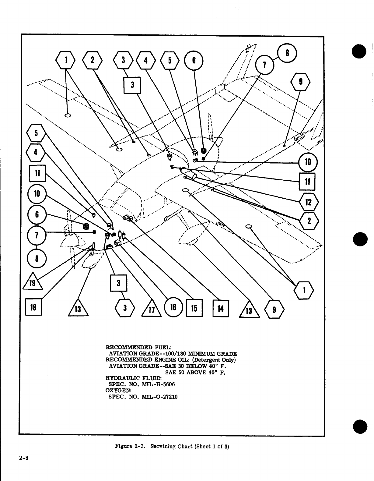
RECOMMENDED
AVIATION
RECOMMENDED
AVIATION
HYDRAULIC
SPEC.
OXYGEN:
SPEC.
GRADE--100/130
GRADE--SAE
FLUID
NO.
MIL-H-5606
NO.
MIL-0-27210
FUEL:
ENGINE
SAE
MINIMUM
OIL:
(Detergent
30
BELOW
50
ABOVE
GRADE
40°
400
Only)
F.
F.
2-8
Figure
2-3.
Servicing
Chart
(Sheet 1
of
3)
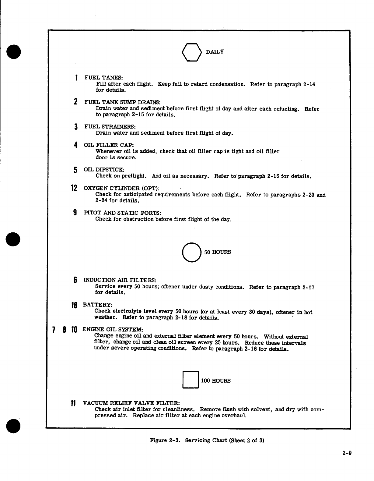
FUEL
TANKS:
Fill
for
after
details.
each
flight.
Keep
full
to
retard
DAILY
condensation.
Refer
to
paragraph
2-14
2
3
4
5
12
9
TANK
FUEL
Drain
paragraph
to
STRAINERS:
FUEL
Drain
OIL
FILLER
Whenever
door
OIL
DIPSTICK:
Check
OXYGEN
Check
2-24
PITOT
AND
Check
SUMP
and
water
2-15
and
water
CAP:
oil
is
secure.
is
on
preflight.
CYLINDER
anticipated
for
for
details.
STATIC
for obstruction
DRAINS:
sediment
for
sediment
added,
Add
(OPT):
PORTS:
before
details.
before
check
that
necessary.
oil
as
requirements
first
before
first
first
1
oil
before
flight
flight
flight
filler
of
50
of
day and
of
day.
cap
Refer
each
day.
the
HOURS
is
tight
to
flight.
after
oil
and
paragraph
Refer
each
filler
2-16
to
refueling.
for
paragraphs
details.
Refer
2-23
and
7
8
6
INDUCTION
16
BATTERY:
ENGINE
10
VACUUM
11
AIR
details.
electrolyte
OIL
change
severe
every
Refer
SYSTEM:
Service
for
Check
weather.
Change engine
filter,
under
RELIEF
air
Check
pressed
inlet
air.
FILTERS:
50
hours;
level
paragraph
to
oil
and
oil
and
operating
VALVE
filter
Replace
oftener
every
external
clean
conditions.
FILTER:
for
cleanliness.
air
Figure
oil
filter
2-3.
under
50
hours
2-18
filter
screen
at
dusty
(or
details.
for
element
every
Refer
1
100
Remove
each
Servicing
at least
to
HOURS
engine
Chart
conditions.
every
every
50
25
hours.
paragraph
flush
overhaul.
(Sheet
hours.
with
Refer
30
days), oftener
Reduce
2-16
for
solvent,
3)
2
of
to
paragraph
Without
these
details.
and
external
intervals
dry
2-17
in
with
hot
com-
2-9
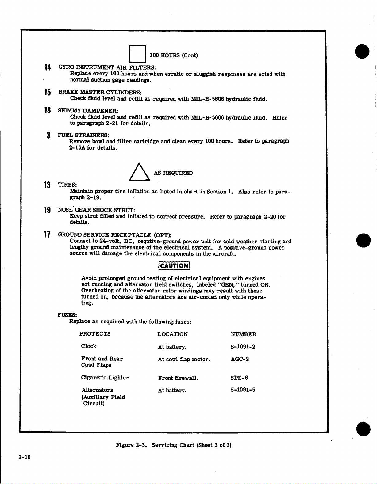
14
15
18
3
GYRO
INSTRUMENT
Replace
normal suction
BRAKE
SHIMMY
FUEL
MASTER CYLINDERS:
Check
Check
paragraph
to
STRAINERS:
Remove
2-15A
100
every
gage
fluid
level
DAMPENER:
fluid
bowl
for
level
2-21
and
details.
AIR
hours
and
and
for
filter
FILTERS:
and
readings.
as
refill
refill
as
details.
cartridge
100
HOURS
when
required
required
and
erratic
with
clean
(Cont)
or
MIL-H-5606
MIL-H-5606
with
every
sluggish
100
responses
hydraulic
hydraulic
hours.
are
Refer
noted
fluid.
fluid.
to
paragraph
with
Refer
13
19
17
TIRES:
Maintain
graph
NOSE
GEAR
Keep
details.
GROUND
Connect
lengthy
source
FUSES:
Replace
proper
2-19.
SHOCK
filled
strut
SERVICE
24-volt,
to
ground
will
damage
Avoid
prolonged
not
running
Overheating
as
on,
required
turned
ting.
PROTECTS
Clock
/\
tire
inflation
STRUT:
inflated
and
RECEPTACLE
DC,
maintenance
and
of
because
negative-ground
electrical
the
ground
alternator
the
alternator
the
with
the
AS
REQUIRED
as
listed
correct
to
(OPT):
of
the
electrical
components
CAUTION
testing
alternators
of
field
rotor
following
LOCATION
battery.
At
in
chart
pressure.
power
electrical
switches,
windings
are
fuses:
Also
Section
in
unit
system. A positive-ground
the
in
equipment
labeled
may
air-cooled
Refer
for
aircraft.
"GEN,"
result
only
1.
to
cold
with
while
NUMBER
S-1091-2
refer
paragraph
weather
engines
turned
with
these
opera-
to
2-20
starting
power
ON.
para-
for
and
2-10
and
Front
Cowl
Flaps
Cigarette
Alternators
(Auxiliary
Circuit)
Rear
Lighter
Field
Figure
2-3.
At
cowl
Front
battery.
At
Servicing
motor.
flap
firewall.
Chart
(Sheet
3
of
3)
AGC-2
SPE-6
S-1091-5
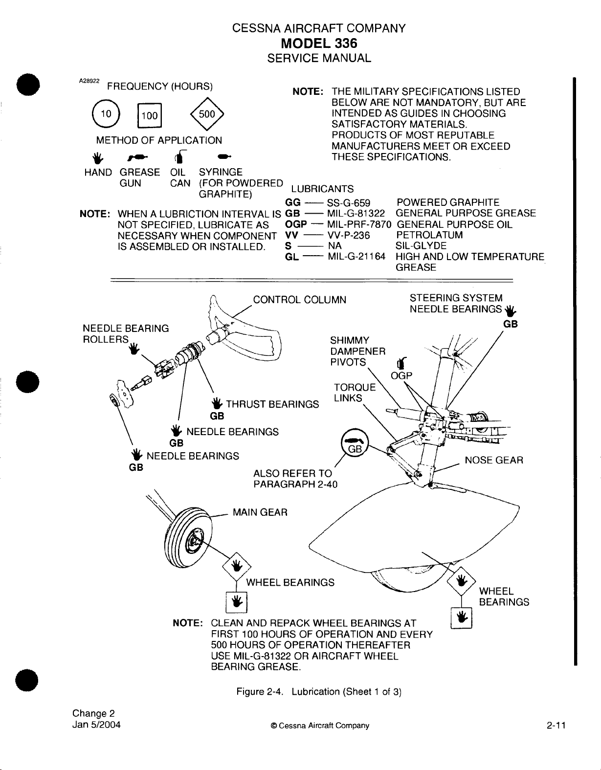
A28922
FREQUENCY
METHOD
HAND
NOTE:
CESSNA
SERVICE
(HOURS)
OF
APPLICATION
GREASE
GUN
WHEN A LUBRICTION INTERVAL
NOT
NECESSARY
IS
ASSEMBLED
OIL
CAN
SPECIFIED,
WHEN
OR
SYRINGE
(FOR
POWDERED
GRAPHITE)
GRAPHITE)
LUBRICATE AS
COMPONENT
INSTALLED.
AIRCRAFT
MODEL
COMPANY
336
MANUAL
NOTE: THE
LUBRICANTS
GG
-
IS
GB
--
OGP -MIL-PRF-7870
VV
--
S
GL -
MILITARY SPECIFICATIONS
BELOW
INTENDED
SATISFACTORY
PRODUCTS
MANUFACTURERS
THESE
SPECIFICATIONS.
SS-G-659
MIL-G-81322 GENERAL
VV-P-236
NA
MIL-G-21164
ARE
NOT
AS
GUIDES
OF
MOST
POWERED
GENERAL
PETROLATUM
SIL-GLYDE
HIGH AND
GREASE
MANDATORY,
IN
CHOOSING
MATERIALS.
REPUTABLE
MEET
OR
GRAPHITE
PURPOSE
PURPOSE
LOW
LISTED
BUT
ARE
EXCEED
GREASE
OIL
TEMPERATURE
NEED
ROLL
GB
ROL
COLUMN
ARINGS
SHIMMY
DAMPENER
STEERING
NEEDLE
BEARINGS
SYSTEM
,
GB
Change
Jan
5/2004
FIRST
500
USE
BEARING
100
HOURS OF
HOURS
OF
MIL-G-81322
GREASE.
Figure
2-4.
OPERATION
OPERATION
OR
AIRCRAFT
Lubrication
AND
EVERY
THEREAFTER
WHEEL
(Sheet 1 of
3)
2
©
Cessna
Aircraft
Company
2-11
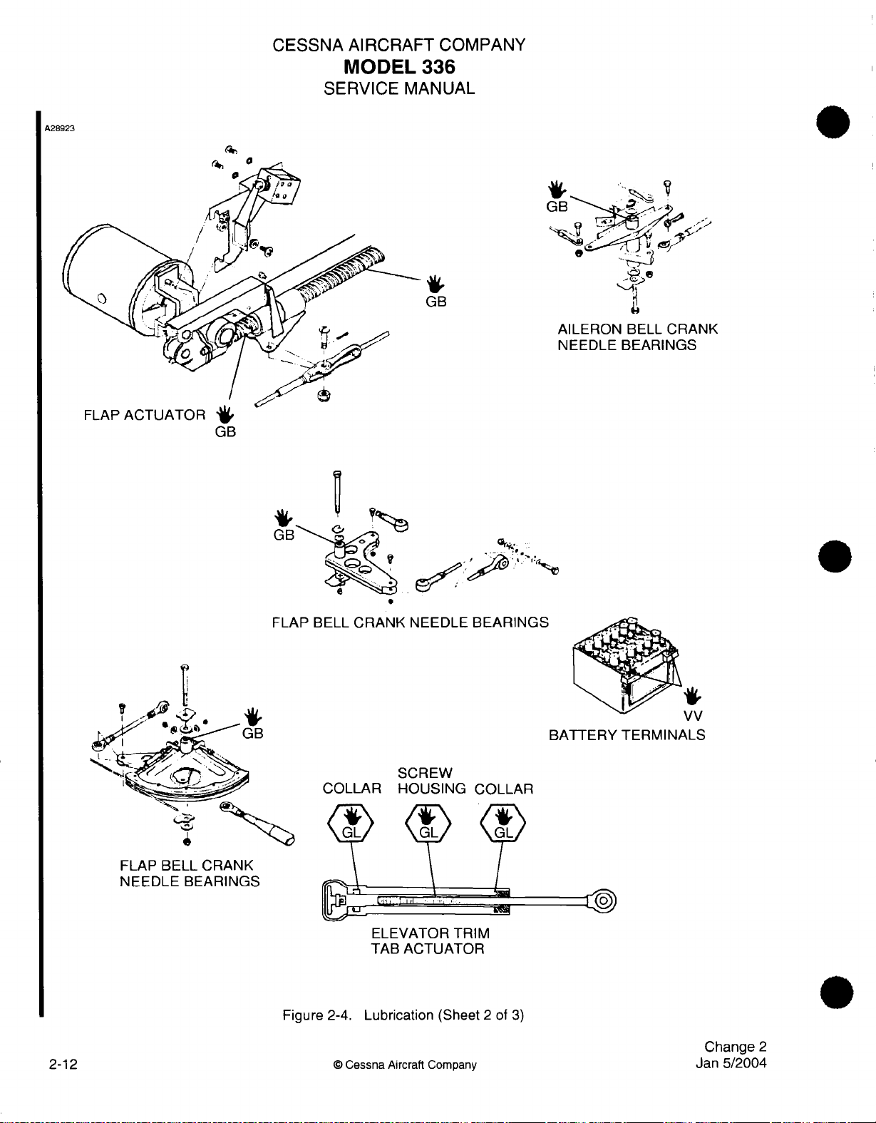
A28923
CESSNA
SERVICE
AIRCRAFT
MODEL
336
MANUAL
GB
COMPANY
FLAP
ACTUATOR
*
GB
FLAP
BELL
CRANK
NEEDLE
BEARINGS
Figure
2-4.
©
Cessna
Lubrication
Aircraft
(Sheet
Company
2
of
3)
Change
Jan
5/2004
2
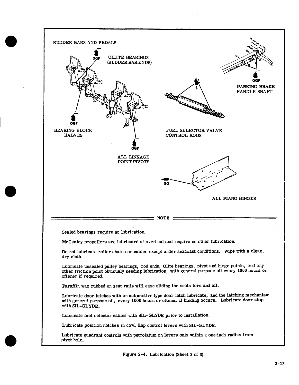
RUDDER
BARS
AND
PEDALS
OGP
PARKING
HANDLE
-
BRAKE
SHAFT
BEAR
Sealed
McCauley
Do
not
dry
cloth.
Lubricate
other friction
oftener
bearings
propellers
lubricate
unsealed
if
required.
require
point
roller
pulley
obviously
are
chains
ALL
POINT
no
lubrication.
lubricated
bearings,
needing
OGP
LINKAGE
PIVOTS
or
cables
at
overhaul
except
rod
ends,
lubrication,
FUEL
CONTROL
NOTE
and
under
Olite
require
seacoast
bearings,
with
SELECTOR
RODS
no
other
conditions.
pivot
general
purpose
VALVE
ALL
lubrication.
and
hinge
oil
PIANO
Wipe
points,
every
HINGES
with
1000
a
clean,
and any
hours
or
Paraffin
Lubricate
with
general
with
SIL-GLYDE.
Lubricate
Lubricate
Lubricate
pivot
hole.
wax
rubbed
door
purpose
fuel
position
quadrant
latches
selector
notches
controls
on
seat
with an
oil,
cables
rails
every
in
with
Figure
will
automotive
1000
with
SIL-GLYDE
cowl
flap
petrolatum
2-4.
ease
hours
control
Lubrication
sliding
type
door
or oftener
prior
levers
on
levers
the
latch
(Sheet
seats
lubricate,
if
binding
to
installation.
with
SIL-GLYDE.
only
within
3
fore
of
and
occurs.
a
3)
aft.
and
the
Lubricate
one-inch
latching
radius
mechanism
door
stop
from
2-13

To
avoid
only
Some
the
items
repetition
items
are
throughout
to
be
optional
checked
equipment
the inspection,
are
listed
and
that
may
INSPECTION
general
details
not
be
as
to
found
points
how
on
to
be
to
check,
a
particular
checked
or
airplane.
are
what
given
to
check
below.
for,
In
are
the
inspection,
excluded.
CHECK
MOVABLE
safetying,
hinges, defective
FLUID
corrosion,
METAL
condition
WIRING
terioration,
BOLTS
chart
in Section
FILTERS,
intervals.
AIRPLANE
There
are
check
To
be
1.
2.
miscellaneous
list
displayed
is
a
AS
APPLICABLE:
PARTS
proper
LINES
AND
deterioration,
PARTS
of
paint,
for
security,
and
IN
CRITICAL
SCREENS,
Do
not
FILE.
for
that
Aircraft
Aircraft
in
for
lubrication,
operation,
bearings,
HOSES
for
security
and
corroded
1,
when
use
file:
the
Airworthiness
Registration
for
obstructions,
any
other
chafing,
terminals.
AREAS
installed
AND
solvent
data, information,
airplane
servicing,
proper
cleanliness,
of
for
FLUIDS
adjustment,
leaks,
attachment,
apparent
burning,
correct
or
when
for cleanliness,
to
clean
at
all
Certificate
Certificate
corrosion,
cracks,
and
defective
torque
the
and
times:
security
dents,
foreign
cracks,
damage.
in
visual
induction
licenses
(Form
(Form
of
correct
deformation,
kinks,
matter.
metal
insulation,
accordance
inspection
contamination
air
filters.
that
FAA
1362).
FAA
500A).
attachment,
travel,
are a part
cracked
chafing,
distortion,
loose
with
indicates
binding,
fittings,
sealing,
or
the
and/or
and
proper radius,
broken
broken
torque
the need
replacement
of
the
airplane
excessive
security
tensions.
security,
spotwelds,
terminals,
values
for a torque
given
file.
wear,
of
corrosion,
heat
in
check.
at
specified
The
de-
the
following
To
be
In
addition
Regulations,
time
specified
ENGINE
Before
instructions
ancies
2-14
beginning
or
1. Engine
2.
Static
3.
Magneto
4.
Engine
5.
Any
6.
Propeller
carried
1.
2.
3.
4.
5.
6.
to
RUN-UP.
abnormalities:
in
Airplane
Weight
Airplane
Airplane
Engine
Power
checking
check
by
them.
the
in
the
Owner's
temperatures
rpm.
drop
response
unusual
the
airplane
Radio
and
Balance
Equipment
Log
Book.
Log
Books.
Computer.
that
FAA
Airworthiness
step-by-step
(See
to
engine
response
Station
Report
List.
these
documents
Manual.
and
Owner's
changes
noises.
(See
Owner's
at
all
times:
License,
or
Directives
inspection,
During
pressures.
Manual).
in
power.
Manual).
if
latest
are
start,
the
transmitter
copy
of
up-to-date
and
Cessna
run
run-up,
installed
Repair
and
up,
and
observe
and
in
accordance
Service
shut
the
(Form
Alteration
following,
Letters
down
FCC
the
404-2).
Form
with
for
engine
making
(Form
current
compliance
Federal
in
accordance
note
FAA-337).
Air
at
the
of
any
discrep-
with
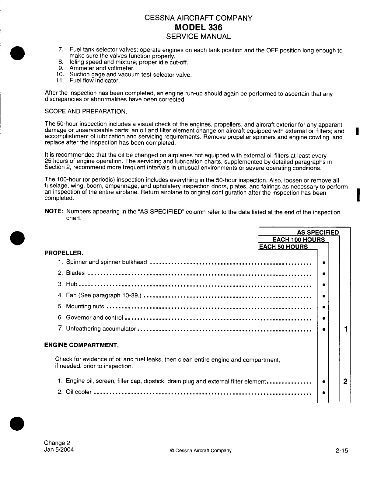
7.
Fuel
make
8.
Idling
9.
Ammeter
10.
Suction
11.
Fuel
After
the
inspection
discrepancies
tank
selector valves; operate
sure
the
valves function
speed
and
mixture;
and
voltmeter.
gage
and
vacuum
flow
indicator.
been
has
or
abnormalities
completed,
have
CESSNA AIRCRAFT
MODEL
SERVICE
properly.
proper
test
selector
been
engines
idle
an
engine
corrected.
cut-off.
valve.
on
each
run-up
COMPANY
336
MANUAL
tank position
should again
and
the
be
performed
OFF
position
to
ascertain
long
enough
that
any
to
SCOPE
The
damage
accomplishment
replace
It
25
Section
The 100-hour
fuselage,
an
completed.
NOTE:
PROPELLER.
AND
PREPARATION.
50-hour inspection
or
unserviceable
after
the
is
recommended
hours
of
engine
2,
recommend
(or
wing,
inspection
1.
2.
3.
of
Numbers appearing
chart.
Spinner
Blades
Hub
............................................................................
includes a visual check
parts;
an
oil
and
of
lubrication
inspection
that
operation.
more
periodic)
boom,
empennage,
the
entire
and
spinner
.........................................................................
has
the
oil
frequent
inspection
airplane.
in
bulkhead
and
been
be
changed
The
the
servicing
completed.
servicing
intervals
includes everything
and
upholstery
Return
"AS
SPECIFIED"
.....................................................
of
the
engines, propellers,
filter element change
requirements.
on
airplanes
and
lubrication
in
airplane
not
unusual
inspection
to
original
column
environments
in
on
aircraft
Remove
equipped
charts,
the
refer
propeller spinners
with
supplemented
or
50-hour inspection.
doors,
plates,
configuration after
to
the
data
and
aircraft
equipped
external
severe
and
fairings
listed
EACH
exterior
with
and
oil
filters
by
detailed
operating
Also,
the
inspection
at
the
EACH
50
for
external
engine
at
least
paragraphs
conditions.
loosen
as
necessary
end
of
AS
100
HOURS
any
apparent
oil
filters;
cowling,
every
or
remove
to
has
been
the
inspection
SPECIFIED
HOURS
and
and
in
all
perform
|
4. Fan
5.
6.
7.
ENGINE
Check
if
needed,
1.
2.
Change
Jan
5/2004
(See
paragraph
Mounting
Governor
Unfeathering
COMPARTMENT.
for
Engine
Oil
2
evidence
prior
oil,
cooler
nuts
..................................................................
and
control
accumulator
to
inspection.
screen,
.......................................................................
of
10-39.)
oil
and
filler
......................................................
..................................... .......................
.........................................................
fuel leaks,
cap,
dipstick,
clean entire
then
drain
plug
©
Cessna Aircraft
and
engine
external
Company
and
compartment,
element
filter
...............
1
* 2
2-15

CESSNA AIRCRAFT
MODEL
SERVICE
336
MANUAL
COMPANY
EACH
EACH
50
HOURS
AS SPECIFIED
100
HOURS
Induction
3.
Induction
4.
Cold
5.
6.
Engine
Cylinders,
7.
Crankcase,
8.
All
lines
9.
Intake
10.
11.
Ignition
12.
Spark
13.
Crankcase
14.
Electrical
Vacuum
15.
Vacuum relief
16.
17.
Engine
18.
Engine
air
filter .................................................................
air
box,
and
hot
air
baffles
rocker
oil
sump,
hoses................................................................
and
and
exhaust systems
harness
plugs
and
and
wiring
pump
valve
controls
shock
mounts,
valves,
air
hoses
doors,
and controls
......................................
............................................................
...................................................................
box
covers,
accessory
and
section,
(Also
push
see
housings
rod
and
front
paragraph
.........
crankshaft
10-84.)
..............................
..................................................................
compression
vacuum
check ................................................
lines
system
breather
........................................
..................................................................
and
relief
valve
..............
.....................................
filter.......... .................................................
and
linkage
........................................................
engine mount structure,
and
ground
straps
seal
......................
.......................
3
.........................
.
*
2-16
19.
Cabin
20.
Starter,
21.
Starter
Alternator
22.
Alternator
23.
Voltage
24.
25.
Magnetos
26.
Magneto
27.
Magneto
Fuel
28.
Engine
29.
Firewall
30.
Engine
31.
Cowl
32.
heat
valves,
solenoid,
brushes,
and
doors,
and
brush
electrical
brushes,
regulator mounting
(externally)
breaker
timing
injection
compartment
to engine
fuel-air control
fuel injection
controls
electrical
leads,
connections
and
connections
brush
leads,
and
and
electrical
and
electrical
.....................................................
......... .................................................
unit,
nozzle
removal
..............................................
commutator
................................................
commutator
connections
pump,
fuel
and
and
.........................................................................
cowling
..........
flaps control
and
motor
.........................................................
.......................................................
©
..........
leads
.......... .............................
fuel
cleaning
Cessna
Aircraft Company
................................
.......................................
.....................................
......................................
manifold valve,
fuel lines,
.....................................
and
nozzles
....
*
*
.
.
.
*
*
Change
Jan 5/2004
5
6
7
19
2

FUEL SYSTEM
1.
Fuel
strainers,
2.
Fuel
strainer
3.
Electric fuel
4. Fuel
5.
6.
7.
8.
9.
10.
tanks, fuel
Drain
fuel
Fuel
vents
Fuel
selector
Fuel
quantity
Vapor
return
Perform a fuel
detailed
drain
valves,
screens
pumps
and
check
and vent
valves
gages
lines
accomplishment
and
sump
tank interior,
valves
and
and
and
quantity
and
tanks, fuel
check valves
indicating
CESSNA
AIRCRAFT
MODEL 336
SERVICE
and
controls
bowls
....................................................
electric
placards
transmitter
connections
lines, drains,
attachment,
........................................................
..................................................
system
instructions
............................................
units
...........................................
.................... ............
operational
.................................
MANUAL
.........................................
filler
and
COMPANY
caps,
and
placards
outlet screens
test.
Refer
EACH
..................
......................
to
Section
EACH
50 HOURS
11
for
.........
AS
100
SPECIFIED
HOURS
·
8
18
LANDING
1.
Brake
2.
Main
3.
Main
4.
Torque
5.
Nose
6.
Nose
fairing,
7.
Parking
AIRFRAME
1.
Aircraft
2.
Aircraft
3.
Windows,
4.
Seat stops,
5.
Seat
6.
Control
7.
Control
GEAR
fluid,
gear
and
nose
link lubrication
gear strut
gear
and
brake
exterior
structure
windshield,
restraints
column
lock,
lines,
hoses,
wheels,
gear
and
wheels,
torque
system
..................................................................
seat
rails,
and
bearings,
control
linings,
wheel
bearings, spring struts, tires,
wheel
............................................................
shimmy
wheel
links
......... ..................................................
............................................................
................................................................
and
upholstery,
attaching
sprockets,
wheel,
discs,
brake
bearing
bearings,
doors
and
lubrication
dampener servicing
strut,
steering
...................................................
structure,
brackets
control column
..............................................
pulleys,
and
assemblies,
........................................
.....................................
system,
seat mounting
cables,
mechanism
and
and
fairings
shimmy
chains,
master cylinders
........................
and
turnbuckles
.............
..........
..................... ·
dampener,
tire,
*
.............
...
............
·
9
10
8.
9.
Change
Jan
5/2004
Instruments
Gyro
filter
replacement
2
and
markings
...........................................................
.........................................................
©
Cessna
Aircraft
Company
2-17

10.
Magnetic
11.
Instrument
12.
Instrument
13.
Defrosting,
14.
Cabin
15.
Area
16.
Electrical
17.
Exterior
18.
Pitot
19.
Stall
compass
wiring
panel,
heating
upholstery,
beneath
horns,
lights
and
static
warning
compensation
and
shock
system,
trim, sun
floor,
lines,
lights,
.........
systems
sensing
CESSNA
plumbing
mounts,
switches,
.........
unit,
.....................................................
ground
ventilating
visors,
hoses, wires,
circuit breakers,
...........................................................
pitot
heaters,
AIRCRAFT
MODEL
SERVICE
............................
straps,
system,
and
ash-trays
and
.....................
and
MANUAL
cover, decals,
and
......................................
control
fuses,
stall
warning
336
controls
cables
COMPANY
......................
and
labeling
.........................
..........................
and
spare
fuses
heaters
..........
EACH
.........
EACH
50
HOURS
.
.................
AS
100
........
.......
SPECIFIED
HOURS
11
.
.
*
.....
20.
Radios
21.
Radio
22.
Battery,
23.
Battery
24.
Oxygen
25.
Oxygen
26.
De-Ice system
27.
De-Ice
28.
Wings,
CONTROL
In
addition
correct travel
1.
Cables,
2.
Chains,
3.
Trim
4.
Travel
and
radio
antennas
battery
electrolyte
system
supply,
system
front
spar
SYSTEMS
to
the
items
and
terminals,
terminals,
control
wheels,
stops
.....................................................................
controls
................................................
box,
and
level
..................................................................
masks,
plumbing
boots
cap,
listed below,
correct
pulleys,
sprockets,
..........................................................
battery cables
............................................................
and
hoses
...........................................................
..............................................................
rear
spar
cap,
always
cable
tension.
pulley
and
indicators, actuator,
..............................................
..................................................
and
front
check
for
brackets,
chain
cable
guards
and
bungee
spar
web
...............................
correct
guards,
.......................................
direction
turnbuckles,
..................................
of
movement,
and
fairleads
12
13
17
.......
2-18
5.
All
decals
and
labeling
............................................................
Cessna
Aircraft
Company
Change
Jan
5/2004
2
 Loading...