

Cessna SKYLANE RG R182 Pilot Operating Handbook

PILOT'S
OPERATING
HANDBOOK
~
Cessna.
o
SKYLANE
RG
1978 MODEL R182
R18200450
Serial
No.
_
Registration
No
1'113
3_B_h'
_
THIS
HANDBOOK
INCLUDES THE
MATERIAL
REQUIRED
TO
BE
FURNISHED
TO
THE PILOT
BY
CAR
PART 3
COPYRIGHT,
1977
CESSNA AIRCRAFT
COMPANY
WICHITA,
KANSAS, USA
01115-13
-RPC-600-11!77

LIST
OF
EFFECTIVE
PAGES
LIST
OF
EFFECTIVE
PAGES
CESSNA
MODEL
R182
INSERT
LATEST
REVISED
PAGES;
DISPOSE
OF
SUPERSEDED
PAGES.
NOTE: This
handbook
will
be
kept
current
by Service Letters
published
by Cessna
Aircraft
Company.
These are
distributed
to
Cessna Dealers andtothose
who
subscribe
through
the
Owner
Follow-Up
System.
If
you are
not
receiving
subscription service,
you
will
wanttokeep in
touch
with
your
Cessna Dealer
for
information
concerning
the
revision status
of
the
handbook.
Subsequent
revisions should be
examined
immediately
after
receipt;
the
handbook
should
not
be used
for
operational
purposes
untilithas
been
updatedtoa
current
status.
On
a revised page,
the
portionofthe
textorillustration
affectedbythe
revision
is
indicated
by a vertical
lineinthe
outer
marginofthe page.
Dates
of
issue
for
original
and revised pages are:
Original
...0...
10
October
1977
THE
TOTAL NUMBER OF
PAGES
IN THIS
HANDBOOK
IS
312,
CONSISTING OF
THE
FOLLOWING. THIS TOTAL INCLUDES
THE
SUPPLEM[NTS PROVIDED IN SECTION 9
WHICH
COVER
OPTIONAL
SYSTEMS
AVAILABLE IN
THE
AIRPLANE.
Page
#Revision
Page
#Revision
No.
No.
No.
No.
Title
0 5-2 Blank
0
A
0
5-3
thru
5-27
0
i
thru
iii
0
5-28 Blank
0
iv Blank
0
6-1
0
1-1
thru
1-9
0
6-2 Blank
0
1-10 Blank
0
6-3
thru
6-13
0
2-1
0 6-14 Blank
0
2-2
Blank
0 6-15
thru
6-26
0
2-3
thru
2-11
0
7-1
thru
7-44
0
2-12 Blank
0
8-1
0
3-1
thru
3-19
0
8-2 Blank
0
3-20 Blank
0
8-3
thru
8-14
0
4-1
thru
4-11
0
9-1
thru
9-2
0
4-12 Blank
0
Supplements
(126
Pages)
0
4-13
thru
4-24
0
(Refer
to
Section 9 Table
5-1
0
of
Contents
for
Optional
Systems Supplements)
# Zero in this
column
indicatesanoriginal
page.
A

CESSNA
MODEL
R182
CONGRATULATIONS
CONGRATULATIONS
• • • •
V\elcome
to
the
ranks
of
Cessna
owners!
Your
Cessna
has
been
designed
and
constructedtogive
you
the
mostinperformance,
economy,
and
comfort.Itis
our
desire
that
you
will
find
flying
it,
either
for
businessorpleasure,
a pleasant and
profitable
experience.
This Pilot's
Operating
Handbook
has
been
preparedasa
guidetohelp
you
get
the
most
pleasure
and
utility
from
your
airplane.
It
contains
information
about
your
Cessna's
equipment,
operating
procedures,
and
performance;
and
suggestions
for
its servicing
and
Cdre.
We
urge
youtoread it
from
covertocover,
andtorefertoit
frequently,
Our
interestinyour
flying
pleasure
has
not
ceased
with
your
purchaseofa Cessna.
World-wide,
the
Cessna
Dealer
Organization
backed
by
the
Cessna
Customer
Services
Department
stands
readytoserve
you.
The
following
services are
offered
by most Cessna
Dealers:
• THE CESSNA
WARRANTY,
which
provides
coverage
for
parts and
labor,isavailable at
Cessna Dealers
worldwide.
Specific
benefits
and
provisionsofwarranty,
plus
other
important
benefits
for
you,
are
contained
in
your
Customer
Care Program
book,
supplied
with
your
airplane.
Warrantv
serviceisavailabletoyou at
authorized
Cessna
Dealers
throughout
the
world
upon
presentationofyour
Customer
Care Card
which
establishes
your
eligibility
under
the
warranty.
• FACTORY
TRAINED
PERSONNELtoprovide
you
with
courteous
expert
service.
• FACTORY APPROVED SERVICE
EQUIPMENTtoprovide
you
efficient
and accurate
workmanship.
• A STOCK OF
GENUINE
CESSNA SERVICE PARTS
on
hand
when
you
need
them.
• THE LATEST
AUTHORITATIVE
INFORMATION
FOR SERVICING CESSNA
AIR-
PLANES, since Cessna Dealers have allofthe
Service
Manuals
and
Parts Catalogs,
kept
current
by Service Letters
and
Service
News
Letters,
published
by Cessna
Aircraft
Company.
We
urge
all Cessna
ownerstouse
the
Cessna
Dealer
Organization
to
the
fullest.
A
current
Cessna
Dealer
Directory
accompanies
your
new
airplane.
The
Directory
is
revised
frequently,
andacurrent
copy
canbeobtained
from
your
Cessna Dealer.
Make
your
Directory
one
of
your
cross-country
flight
planning
aids; a
warm
welcome
awaits
you
at
every
Cessna
Dealer.
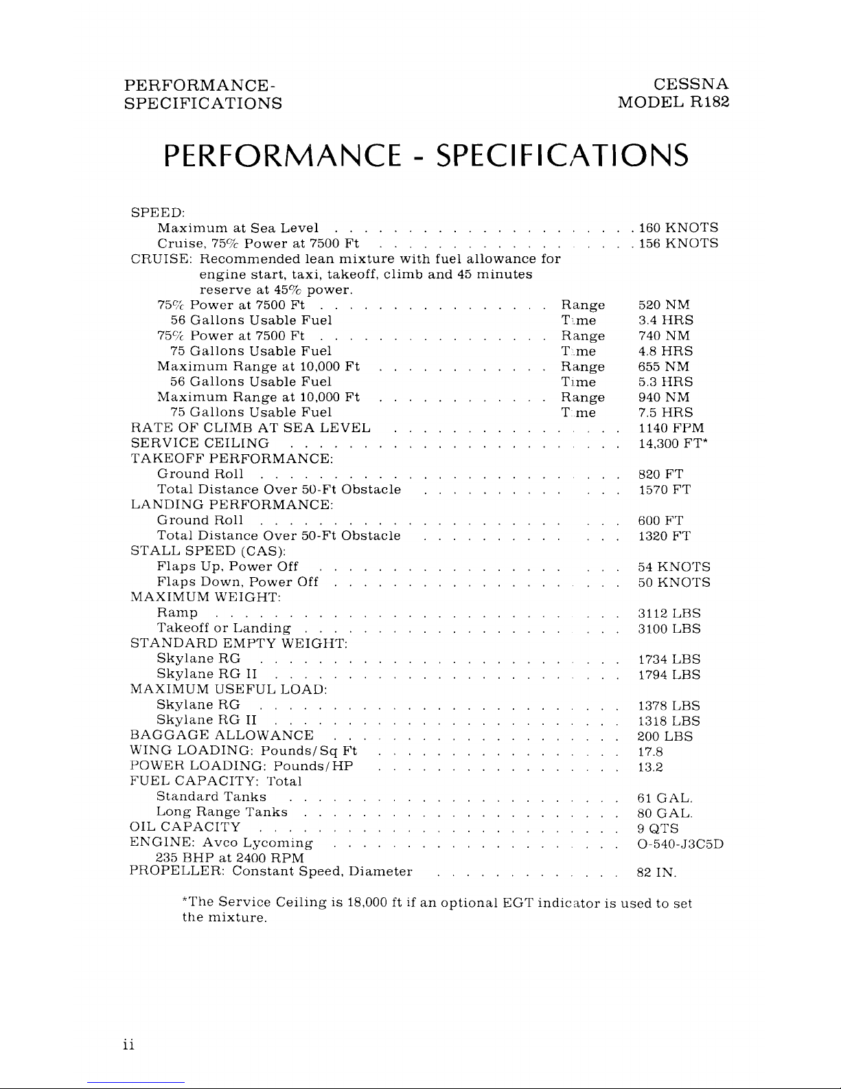
PERFORMANCESPECIFICATIONS
CESSNA
MODEL
R182
PERFORMANCE - SPECIFICATIONS
SPEED:
Maximum
at
Sea
Level
. . . . . . . . . . . . . . . .
Cruise,
75o/c
Power
at
7500
Ft
.
CRUISE:
Recommended
lean
mixture
with
fuel
allowance
for
engine
start,
taxi,
takeoff,
climb
and45minutes
reserve
at
45%
power.
75CJt
Power
at
7500
Ft
56
Gallons
Usable
Fuel
75
c
/c
Power
at
7500
Ft
75
Gallons
Usable
Fuel
Maximum
Range
at
10,000
Ft
56
Gallons
Usable
Fuel
Maximum
Range
at
10,000
Ft
75
Gallons
Usable
Fuel
RATE
OF
CLIMB
AT
SEA
LEVEL
SERVICE
CEILING
TAKEOFF
PERFORMANCE:
Ground
Roll
. . . . . .
Total
Distance
Over
50-Ft
Obstacle
LANDING
PERFORMANCE:
Ground
Roll
. . . . . . . . . .
Total
Distance
Over
50-Ft
Obstacle
STALL
SPEED
(CAS):
Flaps
Up,
Power
Off
Flaps
Down,
Power
Off
MAXIMUM
WEIGHT:
Ramp
.
Takeoff
or
Landing
. .
STANDARD
EMPTY
WEIGHT:
Skylane
RG
.....
Skylane
RG
II
MAXIMUM
USEFUL
LOAD:
Skylane
RG
.....
Skylane
RG
II
BAGGAGE
ALLOWANCE
WING
LOADING:
Pounds/
Sq
Ft
POWER
LOADING:
Pounds/
HP
FUEL
CAPACITY:
Total
Standard
Tanks
Long
Range
Tanks
OIL
CAPACITY
ENGINE:
Avco
Lycoming
235
BHPat2400
RPM
PROPELLER:
Constant
Speed,
Diameter
Range
T'me
Range
Tme
Range
Tlme
Range
Tme
.160
KNOTS
.156
KNOTS
520
NM
3.4
HRS
740
NM
4.8
HRS
655
NM
5.3
HRS
940
NM
7.5
HRS
1140
FPM
14,300 FT*
820
FT
1570
FT
600
FT
1320
FT
54
KNOTS
50
KNOTS
3112
LBS
3100
LBS
1734
LBS
1794
LBS
1378
LBS
1318
LBS
200
LBS
17.8
13.2
61
GAL.
80
GAL.
9
QTS
0-540-J3C5D
82
IN.
*The
Service
Ceilingis18,000ftifanoptional
EGT
indicator
is
usedtoset
the
mixture.
ii

CESSNA
MODEL
R182
T
ABLE
OF
CONTENTS
TABLE
OF
CONTENTS
SECTION
GENERAL 1
LIMITATIONS
2
EMERGENCY
PROCEDURES 3
NORMAL
PROCEDURES 4
PERFORMANCE
5
WEIGHT
&
BALANCE/
EQUIPMENT
LIST 6
AIRPLANE
& SYSTEMS
DESCRIPTIONS
7
AIRPLANE
HANDLING}
SERVICE &
MAINTENANCE
8
SUPPLEMENTS
(Optional
Systems
Description
&
Operating
Procedures)
9
iii/
(iv
blank)

CESSNA
MODEL
R182
SECTION 1
GENERAL
TABLE OF
CONTENTS
SECTION
1
GENERAL
Page
Three
View
1-2
Introduction
1-3
Descriptive
Data
1-3
Engine
1-3
Propeller
1-3
Fuel
. . . 1-3
Oil
1-4
Maximum
Certificated
Weights
1-5
Standard
Airplane
Weights
1-5
Cabin
And
Entry
Dimensions
. 1-5
Baggage
Space
And
Entry
Dimensions
1-5
Specific
Loadings
1-5
Symbols,
Abbreviations
And
Terminology
1-0
General
Airspeed
Terminology
And
Symbols
1-6
Meteorological
Terminology
1-7
Engine
Power
Terminology
. . . . . . . . 1-7
Airplane
Performance
And
Flight
Planning
Terminology
1-7
Weight
And
Balance
Terminology
. . . . . . . . . . . 1-8
1-1

SECTION
1
GENERAL
1-2
MAX.6'-lO"
Figure
1-1.
Three
View
CESSNA
MODEL
R182
NOTES
Wing
span
shown
.....
Ith
nrobe
lights Installed
MaxImum
height
5hown
With
nose gear (jepressed. all tires
and
nose
strut
properly
inflated
and Hashing
~
inst.-IIE1d.
3.
Wheel
base
lengthis65".
4. Propeller ground clearance
is
il
11
1/2"
5.
Wing arell.,174
$Quare
feet.
6. MlnllTlUm
lurning
radius
(.plvot
po,nt
to
oo~(d
wing lip)
is
27',
CESSNA
MODEL
R182
INTRODUCTION
SECTION
1
GENERAL
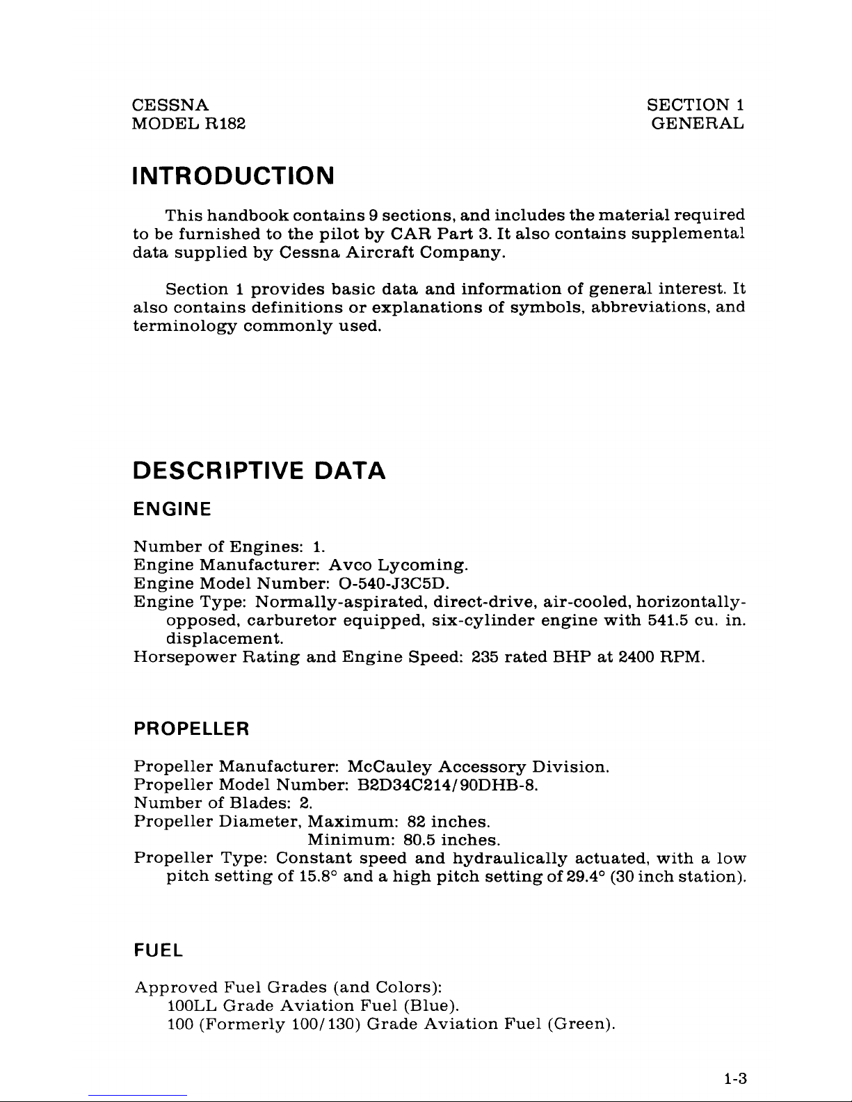
This
handbook
contains9sections,
and
includes
the
material
required
to
be
furnished
to
the
pilot
by
CAR
Part
3.Italso
contains
supplemental
data
supplied
by
Cessna
Aircraft
Company.
Section
1
provides
basic
data
and
information
of
general
interest.
It
also
contains
definitions
or
explanations
of
sYmbols,
abbreviations,
and
terminology
commonly
used.
DESCRIPTIVE
DATA
ENGINE
Number
of
Engines:
1.
Engine
Manufacturer:
Avco
Lycoming.
Engine
Model
Number:
0-540-J3C5D.
Engine
Type:
Normally-aspirated,
direct-drive,
air-cooled,
horizontally-
opposed,
carburetor
equipped,
six-cylinder
engine
with
541.5
cu.
in.
displacement.
Horsepower
Rating
and
Engine
Speed:
235
rated
BHP
at
2400
RPM.
PROPELLER
Propeller
Manufacturer:
McCauley
Accessory
Division.
Propeller
Model
Number:
B2D34C214/90DHB-8.
Number
of
Blades:
2.
Propeller
Diameter,
Maximum:
82
inches.
Minimum:
80.5
inches.
Propeller
Type:
Constant
speed
and
hydraulically
actuated,
with
a
low
pitch
setting
of
15.8°
andahigh
pitch
setting
of
29.4° (30
inch
station).
FUEL
Approved
Fuel
Grades
(and
Colors):
100LL
Grade
Aviation
Fuel
(Blue).
100
(Formerly
100/130)
Grade
Aviation
Fuel
(Green).
1-3

SECTION
1
GENERAL
Fuel
Capacity:
Standard
Tanks:
Total
Capacity:
61
gallons.
Total
Capacity
Each
Tank:
30.5
gallons.
Total
Usable:
56
gallons.
Long
Range
Tanks:
Total
Capacity:
80
gallons.
Total
Capacity
Each
Tank:
40
gallons.
Total
Usable:
75
gallons.
NOTE
CESSNA
MODEL
R182
To
ensure
maximum
fuel
capacity
when
refueling,
place
the
fuel
selector
valve
in
either
LEFT
or
RIGHT
position
to
prevent
cross-feeding.
OIL
Oil
Grade
(Specification):
MIL-L-6082
Aviation
Grade
Straight
Mineral
Oil:
Use
to
replenish
supply
during
first
25
hours
and
at
the
first
25-hour
oil
change.
Continue
to
use
until
a
total
of
50
hours
has
accumulated
or
oil
consumption
has
stabilized.
NOTE
The
airplane
was
delivered
from
the
factory
withacorro-
sion
preventive
aircraft
engine
oil.
This
oil
should
be
drained
after
the
first
25
hours
of
operation.
MIL-L-22851
Ashless
Dispersant
Oil:
This
oil
must
be
used
after
first
50
hours
or
oil
consumption
has
stabilized.
Recommended
Viscosity
For
Temperature
Range:
MIL-L-6082
Aviation
Grade
Straight
Mineral
Oil:
SAE
50
above
16°C
(60°F).
SAE
40
between
-1°C
(30°F)
and
32°C
(90°F).
SAE
30
between
-18°C
(O°F)
and
21°C
(70°F).
SAE
20
below
-12°C
(10°F).
MIL-L-22851
Ashless
Dispersant
Oil:
SAE
40
or
SAE
50
above
16°C
(60°F).
SAE
40
between
-1°C
(30°F)
and
32°C
(90°F).
SAE
30
or
SAE
40
between
-18°C
(O°F)
and
21°C
(70°F).
SAE
30
below
-12°C
(lOOF).
Oil
Capacity:
Sump:
8
Quarts.
Total:
9
Quarts.
1-4

CESSNA
MODEL
R182
MAXIMUM
CERTIFICATED
WEIGHTS
SECTION
1
GENERAL
Takeoff:
3100
lbs.
Landing:
3100
Ibs.
Weight
in
Baggage
Compartment:
Baggage
Area
"A"
(or
passenger
on
child's
seat)-Station
82to110: 120
lbs.
See
note
below.
Baggage
Area
"B"-Station
110
to
134:
80
lbs.
See
note
below.
NOTE
The
maximum
combined
weight
capacity
for
baggage
areas
A
and
Bis200
lbs.
STANDARD
AIRPLANE
WEIGHTS
Standard
Empty
Weight,
Sky
lane
RG:
1734
lbs.
Sky
lane
RG
II: 1794
lbs.
Maximum
Useful
Load,
Skylane
RG:
1378
lbs.
Skylane
RG
II:
1318
lbs.
CABIN
AND
ENTRY
DIMENSIONS
Detailed
dimensions
of
the
cabin
interior
and
entry
door
openings
are
illustrated
in
Section
6.
BAGGAGE
SPACE
AND
ENTRY
DIMENSIONS
Dimensions
of
the
baggage
area
and
baggage
door
opening
are
illustrated
in
detail
in
Section
6.
SPECIFIC
LOADINGS
Wing
Loading:
17.8
lbs./
sq.
ft.
Power
Loading:
13.2
lbs./hp,
1-5

SECTION
1
GENERAL
SYMBOLS,
ABBREVIATIONS
AND
TERMINOLOGY
CESSNA
MODEL
R182
GENERAL
AIRSPEED
TERMINOLOGY
AND
SYMBOLS
KCAS
KIAS
KTAS
VA
V
NO
V
NE
1-6
Knots
Calibrated
Airspeed
is
indicated
airspeed
corrected
for
position
and
instrument
error
and
expressed
in
knots.
Knots
calibrated
airspeed
is
equal
to
KTAS
in
standard
atmosphere
at
sea
level.
Knots
Indicated
Airspeed
is
the
speed
shown
on
the
airspeed
indicator
and
expressed
in
knots.
Knots
True
Airspeed
is
the
airspeed
expressed
in
knots
relative
to
undisturbed
air
which
is
KCAS
corrected
for
altitude
and
temperature.
Manuevering
Speed
is
the
maximum
speed
at
which
you
may
use
abrupt
control
travel.
Maximum
Flap
Extended
Speed
is
the
highest
speed
permissible
with
wing
flaps
in
a
prescribed
extended
position.
Maximum
Landing
Gear
Extended
Speed
is
the
maximum
speed
at
which
an
airplane
can
be
safely
flown
with
the
landing
gear
extended.
Maximum
Landing
Gear
Operating
Speed
is
the
maximum
speed
at
which
the
landing
gear
can
be
safely
extended
or
retracted.
Maximum
Structural
Cruising
Speed
is
the
speed
that
should
notbeexceeded
except
in
smooth
air,
then
only
with
caution.
Never
Exceed
Speed
is
the
speed
limit
that
may
not
be
exceeded
at
any
time.
Stalling
Speed
or
the
mlnunum
steady
flight
speed
at
which
the
airplane
is
controllable.
Stalling
Speed
or
the
minimum
steady
flight
speed
at
which
the
airplane
is
controllable
in
the
landing
configu-
ration
at
the
most
forward
center
of
gravity.

CESSNA
MODEL
R182
v
X
SECTION
1
GENERAL
Best
Angle-of-Climb
Speed
is
the
speed
which
results
in
the
greatest
gain
of
altitude
inagiven
horizontal
distance.
Best
Rate-of-Climb
Speed
is
the
speed
which
results
in
the
greatest
gain
in
altitude
inagiven
time.
METEOROLOGICAL
TERMINOLOGY
OAT
Standard
Tempera·
ture
Pressure
Altitude
Outside
Air
Temperature
is
the
free
air
static
temperature.
Itisexpressed
in
either
degrees
Celsius
(formerly
Centi-
grade)
or
degrees
Fahrenheit.
Standard
Temperature
is
15°C
at
sea
level
pressure
alti-
tude
and
decreases
by
2°C
for
each
100(\
feet
of
altitude.
Pressure
Altitude
is
the
altitude
read
irom
an
altimeter
when
the
altimeter's
barometric
scale
h,ts
been
set
to
29.92
inches
of
mercury
(1013
mb).
ENGINE
POWER
TERMINOLOGY
BHP
RPM
MP
Brake
Horsepower
is
the
power
de\-'
oped
by
the
engine.
Revolutions
Per
Minute
is
engine
S'
·c~ed.
Manifold
Pressure
isapressure
m~
.:::iUredinthe
engine's
induction
system
and
is
expressec
ill
inches
of
mercury
(Hg).
AIRPLANE
PERFORMANCE
AND
FLIGHT
PLANNING
TERMINOLOGY
Demonstrated
Crosswind
Velocity
Usable
Fuel
Unusable
Fuel
GPH
Demonstrated
Crosswind
Velocity
is
the
velocity
of
the
crosswind
component
for
which
adequate
control
of
the
airplane
during
takeoff
and
landing
was
actually
demon-
strated
during
certification
tests.
The
value
shown
is
not
considered
to
be
limiting.
Usable
Fuel
is
the
fuel
available
for
flight
planning.
Unusable
Fuel
is
the
quantity
of
fuel
that
can
not
be
safely
used
in
flight.
Gallons
Per
Hour
is
the
amount
of
fuel
(in
gallons)
consumed
per
hour.
1-7

SECTION
1
GENERAL
NMPG
g
CESSNA
MODEL
R182
Nautical
Miles
Per
Gallon
is
the
distance
(in
nautical
miles)
which
can
be
expected
per
gallon
of
fuel
consumed
ataspecific
engine
power
setting
andl
or
flight
configura-
tion.
g
is
acceleration
due
to
gravity.
WEIGHT
AND
BALANCE
TERMINOLOGY
Reference
Datum
Station
Arm
Moment
Center
of
Gravity
(C.G.)
C.G.
Arm
C.G.
Limits
Standard
Empty
Weight
Basic
Empty
Weight
Useful
Load
1-8
Reference
Datum
is
an
imaginary
vertical
plane
from
which
all
horizontal
distances
are
measured
for
balance
purposes.
Station
isalocation
along
the
airplane
fuselage
given
in
terms
of
the
distance
from
the
reference
datum.
Arm
is
the
horizontal
distance
from
the
reference
datum
to
the
center
of
gravity
(C.G.)
of
an
item.
Moment
is
the
product
of
the
weight
of
an
item
multiplied
by
its
arm.
(Moment
divided
by
the
constant
1000isused
in
this
handbook
to
simplify
balance
calculations
by
reduc-
ing
the
number
of
digits.)
Center
of
Gravity
is
the
point
at
which
an
airplane,
or
equipment,
would
balance
if
suspended.
Its
distance
from
the
reference
datum
is
found
by
dividing
the
total
moment
by
the
total
weight
of
the
airplane.
Center
of
Gravity
Arm
is
the
arm
obtained
by
adding
the
airplane's
individual
moments
and
dividing
the
sum
by
the
total
weight.
Center
of
Gravity
Limits
are
the
extreme
center
of
gravity
locations
within
which
the
airplane
must
be
operated
at
a
given
weight.
Standar1
Empty
Weight
is
the
weight
ofastandard
air-
plane,
including
unusable
fuel,
full
operating
fluids
and
full
engine
oil.
Basic
Empty
Weightisthe
standard
empty
weight
plus
the
weight
of
optional
equipment.
Useful
Loadisthe
difference
between
ramp
weight
and
the
basic
empty
weight.

CESSNA
MODEL
R182
Maximum
Ramp
Weight
Gross
(Loaded)
Weight
Maximum
Takeoff
Weight
Maximum
Landing
Weight
Tare
SECTION
1
GENERAL
Maximum
Ramp
Weight
is
the
maximum
weight
approved
for
ground
maneuver.
(It
includes
the
weight
of
start,
taxi
and
runup
fuel.)
Gross
(Loaded)
Weight
is
the
loaded
weight
of
the
airplane.
Maximum
Takeoff
Weight
is
the
maximum
weight
approved
for
the
start
of
the
takeoff
run.
Maximum
Landing
Weight
is
the
maximum
weight
approved
for
the
landing
touchdown.
Tare
is
the
weight
of
chocks,
blocks,
stands,
etc.
used
when
weighing
an
airplane,
and
is
included
in
the
scale
read-
ings.
Tare
is
deducted
from
the
scale
reading
to
obtain
the
actual
(net)
airplane
weight.
1-9/(1-10
blank)

CESSNA
MODEL
R182
SECTION 2
LIMIT
ATIONS
TABLE OF
CONTENTS
Introduction
. . . . . . . .
Airspeed
Limitations
Airspeed
Indicator
Markings
Power
Plant
Limitations
Power
Plant
Instrument
Markings
Weight
Limits
. . . . .
Center
Of
Gravity
Limits
.
Maneuver
Limits
Flight
Load
Factor
Limits
Kinds
Of
Operation
Limits
Fuel
Limitations
Placards
.
SECTION
2
LIMITATIONS
Page
2-3
2-4
2-4
2-5
2-6
2-6
2-7
2-7
2-7
2-7
2-8
2-9
2-1/
(2-2
blank)
CESSNA
MODEL
R182
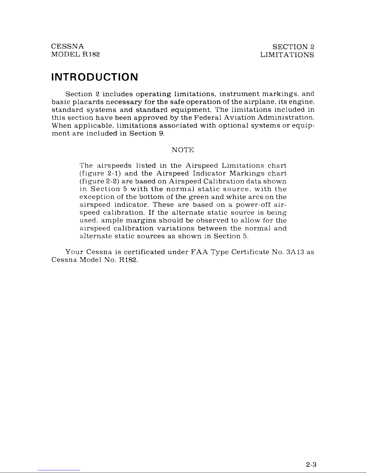
INTRODUCTION
SECTION
2
LIMITATIONS
Section
2
includes
operating
limitations,
instrument
markings,
and
basic
placards
necessary
for
the
safe
operation
of
the
airplane,
its
engine,
standard
systems
and
standard
equipment.
The
limitations
included
in
this
section
have
been
approved
by
the
Federal
Aviation
Administration.
When
applicable,
limitations
associated
with
optional
systems
or
equip-
ment
are
included
in
Section
9.
NOTE
The
airspeeds
listed
in
the
Airspeed
Limitations
chart
(figure
2-1)
and
the
Airspeed
Indicator
Markings
chart
(figure
2-2)
are
based
on
Airspeed
Calibration
data
shown
in
Section
5
with
the
normal
static
source.
with
the
exception
of
the
bottom
of
the
green
and
white
arcs
on
the
airspeed
indicator.
These
are
based
onapower-off
air-
speed
calibration.
If
the
alternate
static
source
is
being
used.
ample
margins
should
be
observed
to
allow
for
the
airspeed
calibration
variations
between
the
normal
and
alternate
static
sources
as
shown
in
Section
5.
Your
Cessna
is
certificated
under
FAA
Type
Certificate
No.
3A13
as
Cessna
Model
No.
R182.
2-3

SECTION
2
LIMITATIONS
AIRSPEED
LIMITATIONS
CESSNA
MODEL
R182
Airspeed
limitations
and
their
operational
signifi(~ance
are
shown
in
figure
2-1.
SPEED
KCAS
KIAS
RI=MAR
KS
I
V',\JE
I
[\Jevcr
Exceed
Spef~d
175
182
Do
not
excetd
this
speed
In
!
I
any
operatloll
I
V
NO
I
Maximum
Structural
140
143
Do
not
excetd
this
speed
I
Cru
ISlrIlJ
Speed
exceptinsmiJoth
air,
and
then
only
wih
caution.
I
VA
Maneuveri
ng Speed.
3100
Pounds
111
112
Do
not
make
full
or
abrupt
I
2550
Pounds
100
101
control
movements
above
2000
Pounds
89
89
this
speed.
V
FE
Maximum
Flap
Extended
I
Speed
To
10
0
Flaps
137
140
Do
not
excetd
these speeds
10°
40°
Flaps
94
95
with
the
give'l
flap
settings.
VLO
Maximum
L211ldlllg Gear 137
140
Do
not
extendorretract
landirllj
Operating
Speed gear above
this
speed.
V
LE
i
MaximurT'. LdmJirlg
GeCJr
137 140
Do
not
exceed
this
speed
with
I
Ex
tended
Speed
landing
gear
extended
MaXimum
Willdow
Opell
175
182
Do
110t
exceeJ
this
speed
with
Speed
windows
opell.
Figure
2-1.
Airspeed
Limitations
AIRSPEED
INDICATOR
MARKINGS
Airspeed
indicator
markings
and
their
color
code
significance
are
shown
in
figure
2-2.
2-4

CESSNA
MODEL
R182
r-
I
'v1ARt<!r\Jl~
KIA.S
VALUE
OR
RANG[
SECTION
2
LIMITATIONS
SIGNIFICANCE
!
I
37-95
FUll
Flap
Operating
ReJrlLJe
Lower
i
limit
IS
rT1CJXlmum
weight
V
So
In
i i 1.;:ldl::cJ
lOl1
t
iguratlorl
Upper
11I11,t
I i
IS
rndximurn
speed
perr
1
11ssible
with
I
flaps
extcllded.
r---------------+-------r-------------------I
.]rcell
Arr.
I 42 - 143 f\JorlT1dl
Operatlricj
Rcll1Cjl
Luwer
!Imit
I
liS
lrIiJXII11Urn
weight
V
s
cH
most
forW,Hd
ell
With
fidPS
retracted.
Upper
IllTIlt
i is
rrUX:fl~UITI
structural
cru,s:rHj
spel:d
r-------------
1
'-----------I--------------------
I y ,'I
"mArl
i
143-
182 I
~~~~~~)~~u(:~~dlT~J~l~~
~~
~~~~~~~,t~J~r
With
~----------+
~--------------------j
: I I
' ::j"d
Line
!
182
I McJxrlllurn speed
for
ail
()~H:rdtlons
Figure
2-2.
Airspeed
Indicator
Markings
POWER
PLANT
LIMITATIONS
Engine
Manufacturer:
A
vco
Lycoming
Engine
Model
Number:
0-540-J3C5D.
Engine
Operating
Limits
for
Takeoff
and
Continuous
Operations:
Maximum
Power:
235
BHP.
Maximum
Engine
Speed:
2400
RPM.
Maximum
Cylinder
Head
Temperature:
260°C
(500CF).
Maximum
Oil
Temperature:
118°C
(245coF).
Oil
Pressure.
Minimum:
25
psi.
Maximum:
100
psi.
Fuel
Pressure,
Minimum:
0.5
psi.
Maximum:
8.0
psi.
Propeller
Manufacturer:
McCauley
Accessory
Division.
Propeller
Model
Number:
B2D34C214/90DHB-8
Propeller
Diameter.
Maximum:
82
inches.
Minimum:
80.5
inches.
Propeller
Blade
Angle
at
30
Inch
Station,
Low:
15.8°.
High:
29.4°.
2-5

SECTION
2
LIMITATIONS
CESSNA
MODEL
R182
POWER PLANT
INSTRUMENT
MARKINGS
Power
plant
instrument
markings
and
their
color
code
significance
are
shown
in
figure
2-3.
RED
LINE
GREEN
ARC
YELLOW
ARC
RED
LINE
INSTRUMENT
MINIMUM
NORMAL
CAUTION
MAXIMUM
LIMIT
OPERATI
NG
RANGE
LIMIT
TJchorneter
- -
2100
- - -
2400
RPM
2400
RPM
Manifold
Pressure
-
--
15-23
- - -
-
--
in. Hg
011
Temperature
-
--
100°-245°F
- - -
245°F
CyIInder Head
- - -
200°-500°F
- - -
500°F
Temperature
Fuel Pressure
0.5
psi
0.5-8.0
psi
8.0
psi
011
Pressure
25
psi
60-90
psi
100
psi
Car'buretor
Air
- - -
-
--
-15°
to
SoC
- - -
Temperature
Figure
2-3.
Power
Plant
Instrument
Markings
WEIGHT
LIMITS
Maximum
Takeoff
Weight:
3100
lbs.
Maximum
Landing
Weight:
3100
lbs.
Maximum
Weight
in
Baggage
Compartment:
Baggage
Area
"A"
(or
passenger
on
child's
seat)-Station
82to110: 120
lbs.
See
note
below.
Baggage
Area
"B"-Station
110
to
134: 80
lbs.
See
note
below.
NOTE
The
maximum
combined
weight
capacity
for
baggage
areas
A
andBis
200
lbs.
2-6

CESSNA
MODEL
R182
CENTER
OF
GRAVITY
LIMITS
SECTION
2
LIMITATIONS
Center
of
Gravity
Range:
Forward:
33.0
inches
aftofdatum
at
2250
lbs.
or
less,
with
straight
line
variation
to
35.5
inches
aftofdatum
at
2700
lbs.,
with
straight
line
variation
to
40.9
inches
aft
of
datum
at
3100
lbs.
Aft:
47.0
inches
aft
of
datum
at
all
weights.
Moment
Change
Due
To
Retracting
Landing
Gear:
+3052
lb.-ins.
Reference
Datum:
Front
face
of
firewall.
MANEUVER
LIMITS
This
airplane
is
certificated
in
the
normal
category.
The
normal
category
is
applicable
to
aircraft
intended
for
non-aerobatic
operations.
These
include
any
maneuvers
incidental
to
normal
flying,
stalls
(except
whip
stalls),
lazy
eights,
chandelles,
and
steep
turns
in
which
the
angle
of
bank
is
not
more
than
60
0
•
Aerobatic
maneuvers,
including
spins,
are
not
approved.
FLIGHT LOAD
FACTOR
LIMITS
Flight
Load
Factors:
*Flaps
Up:
+3.8g,
-1.52g
*Flaps
Down:
+2.0g
*The
design
load
factors
are
150%
of
the
above,
and
in
all
cases.
the
structure
meets
or
exceeds
design
loads.
KINDS
OF
OPERATION
LIMITS
The
airplane
is
equipped
for
day
VFR
and
may
be
equipped
for
night
VFR
and!
or
IFR
operations.
FAR
Part
91
establishes
the
minimum
required
instrumentation
and
equipment
for
these
operations.
The
refer-
ence
to
types
of
flight
operations
on
the
operating
limitations
placard
reflects
equipment
installed
at
the
time
of
Airworthiness
Certificate
issuance.
Flight
into
known
icing
conditions
is
prohibited.
2-7

SECTION
2
LIMITATIONS
FUEL
LIMITATIONS
2
Standard
Tanks:
30.5U.S.
gallons
each.
Total
Fuel:
61
U.
S.
gallons.
Usable
Fuel
(all
flight
conditions):
56
U.
S.
gallons.
Unusable
Fuel:
5.0U.S.
gallons.
2
Long
Range
Tanks:
40U.S.
gallons
each.
Total
Fuel:
80 U .S.gallons.
Usable
Fuel
(all
flight
conditions):
75
U.S.
gallons.
Unusable
Fuel:
5.0U.S.
gallons.
NOTE
CESSNA
MODEL
R182
To
ensure
maximum
fuel
capacity
when
refueling,
place
the
fuel
selector
valve
in
either
LEFT
or
RIG
HT
position
to
prevent
cross-feeding.
NOTE
Takeoff
and
land
with
the
fuel
selector
valve
handle
in
the
BOTH
position.
Approved
Fuel
Grades
(and
Colors):
100LL
Grade
Aviation
Fuel
(Blue).
100
(Formerly
100/130)
Grade
Aviation
Fuel
(Green).
2-8

CESSNA
MODEL
R182
PLACARDS
SECTION
2
LIMITATIONS
The
following
information
is
displayed
in
the
form
of
composite
or
individual
placards.
1.
In
full
view
of
the
pilot:
(The
"DAY
-NIGHT-VFR-IFR"
entry,
shown
on
the
example
below,
will
vary
as
the
airplane
is
equipped.)
This
airplane
must
be
operated
asanormal
category
airplane
in
compliance
with
the
operating
limitations
as
stated
in
the
form
of
placards,
markings,
and
manuals.
--------
MAXIMUMS
--------
GROSS
WEIGHT
. . . .
FLIGHT
LOAD
FACTOR
Flaps
Up
..
Flaps
Down
. 3100
Ibs
+3.8, -1.52
...
+2.0
No
acrobatic
maneuvers,
including
spins,
approved.
Altitude
loss
in
a
stall
recovery
-
240
ft.
Flight
into
known
icing
conditions
prohibited.
This
airplane
is
certified
for
the
follow-
ing
flight
operations
as
of
date
of
original
airworthiness
certificate:
DAY
-NIGHT-
VFR-IFR
2.
Near
airspeed
indicator:
MAX
SPEED-KIAS
MANEUVER
112
GEAR
OPER
140
GEAR
DOWN
140
3.
On
control
lock:
CONTROL
LOCK-REMOVE
BEFORE
STARTING
ENGINE.
2-9

SECTION
2
LIMITATIONS
4.
On
the
fuel
selector
valve
(standard
tanks):
CESSNA
MODEL
R182
OFF
LEFT
- 29
GAL.
LEVEL
FLIGHT
ONLY
BOTH-56
GAL.
ALL
FLIGHT
ATTITUDES
TAKEOFF
AND
LANDING
RIGHT
- 29
GAL.
LEVEL
FLIGHT
ONLY
On
the
fuel
selector
valve
(long
range
tanks):
OFF
LEFT
- 37
GAL.
LEVEL
FLIGHT
ONLY
BOTH
- 75
GAL.
ALL
FLIGHT
ATTITUDES
TAKEOFF
AND
LANDING
RIGHT
- 37
GAL.
LEVEL
FLIGHT
ONLY
5.
On
the
baggage
door:
120
POUNDS
MAXIMUM
BAGGAGE
AND/OR
AUXILIARY
PASSENGER
FORWARD
OF
BAGGAGE
DOOR
LATCH
AND
80
POUNDS
MAXIMUM
BAGGAGE
AFT
OF
BAGGAGE
DOOR
LATCH
MAXIMUM
200
POUNDS
COMBINED
FOR
ADDITIONAL
LOADING
INSTRUCTIONS
SEE
WEIGHT
AND
BALANCE
DATA
6.
On
flap
control
indicator:
2-10
0°
to
10°
10°
to
20°
to
FULL
(Partial
flap
range
with
blue
color
code
and
140
kt
callout;
also,
me-
chanical
detent
at
10°.)
(Indices
at
these
positions
with
white
color
code
and
95ktcallout;
also,
mechanical
detent
at
10°
and
20°.)

CESSNA
MODEL
R182
7.
Forward
of
fuel
tank
filler
cap
(standard
tanks):
SECTION
2
LIMITATIONS
SERVICE
THIS
AIRPLANE
WITH
100LL/l00
MIN.AVIA-
TION
GRADE
GASOLINE
-
CAPACITY
30.5
GAL.
Forward
of
fuel
tank
filler
cap
(long
range
tanks):
SERVICE
THIS
AIRPLANE
WITH
100LL/l00
MIN.
AVIA-
TION
GRADE
GASOLINE
-
CAPACITY
40.0
GAL.
8.
Near
gear
hand
pump:
MANUAL
GEAR
EXTENSION
1.
SELECT
GEAR
DOWN
2.
PULL
HANDLE
FWD
3.
PUMP
VERTICALLY
CAUTION
DO
NOT
PUMP
WITH
GEAR
UP
SELECTED
2-11/
(2-12
blank)

CESSNA
MODEL
R182
SECTION
3
EMERGENCY
PROCEDURES
SECTION 3
EMERGENCY PROCEDURES
TABLE OF
CONTENTS
Page
Introduction
. . . . . . . . . . . .
Airspeeds
For
Emergency
Operation
OPERATIONAL
CHECKLISTS
3-3
3-3
Engine
Failures
3-3
Engine
Failure
During
Takeoff
Run
3-3
Engine
Failure
Immediately
After
Takeoff
3-4
Engine
Failure
During
Flight
. . . . . . 3-4
Forced
Landings
. . . . . . . . . . . . . . 3-4
Emergency
Landing
Without
Engine
Power
3-4
Precautionary
Landing
With
Engine
f)uwer
3-4
Ditching
. . . . . . . . 3-5
Fires
. . . . . . . . . . . 3-5
During
Start
On
Ground
3-5
Engine
Fire
In
Flight
. 3-6
Electrical
Fire
In
Flight
3-6
Cabin
Fire
3-7
Wing
Fire
. . . . . .
3-7
Icing
. . . . . .
3-7
Inadvertent
Icing
Encounter
3-7
Static
Source
Blockage
(Erroneous
Instrument
Reading
Suspected)
. . . . . . . . .
3-8
Landing
Gear
Malfunction
Procedures
3-8
Landing
Gear
Fails
To
Retract
3-8
Landing
Gear
Fails
To
Extend
3-8
Gear
Up
Landing
. . . . . . .
3-9
Landing
Without
Positive
Indication
Of
Gear
Locking
3-9
Landing
With
A
Defective
Nose
Gear
(Or
Flat
1'\ose
Tire)
3-9
Landing
With
A
Flat
Main
Tire
. . . . .
3-10
Electrical
Power
Supply
System
Malfunctions
3-10
Over-Voltage
Light
Illuminates
3-10
Ammeter
Shows
Discharge
3-
10
3-1

SECTION
3
EMERGENCY
PROCEDURES
TABLE OF
CONTENTS
(Continued)
AMPLIFIED
PROCEDURES
Engine
Failure
.
Forced
Landings
.
Landing
Without
Elevator
Control
Fires
. . . . . . . . . . . . .
Emergency
Operation
In
Clouds
(Vacuum
System
Failure)
Executing
A 1800Turn
In
Clouds
Emergency
Descent
Through
Clouds
Recovery
From
A
Spiral
Dive
Flight
In
Icing
Conditions
Static
Source
Blocked
Spins
.
Rough
Engine
Operation
Or
Loss
Of
Power
Carburetor
Icing
. .
Spark
Plug
Fouling
.
Magneto
Malfunction
. . . . . .
Engine-Driven
Fuel
Pump
Failure
Low
Oil
Pressure
. . . . . . . .
Landing
Gear
Malfunction
Procedures
Retraction
Malfunctions
Extension
Malfunctions
Gear
Up
Landing
. . . .
Electrical
Power
Supply
System
Malfunctions
Excessive
Rate
Of
Charge
Insufficient
Rate
Of
Charge
. . . . . . .
3-2
CESSNA
MODEL
R182
Page
3-11
3-12
3-12
3-12
3-13
3-13
3-13
3-14
3-14
3-14
3-15
3-16
3-16
3-16
3-16
3-16
3-16
3-17
3-17
3-17
3-18
3-18
3-18
3-19

CESSNA
MODEL
R182
INTRODUCTION
SECTION
3
EMERGENCY
PROCEDURES
Section3provides
checklist
and
amplified
procedures
for
coping
with
emergencies
that
may
occur.
Emergencies
caused
by
airplane
or
engine
malfunctions
are
extremely
rare
if
proper
preflight
inspections
and
maintenance
are
practiced.
Enroute
weather
emergencies
can
be
minim-
ized
or
eliminated
by
careful
flight
planning
and
good
judgment
when
unexpected
weather
is
encountered.
However,
should
an
emergency
arise,
the
basic
guidelines
described
in
this
section
should
be
considered
and
applied
as
necessary
to
correct
the
problem.
Emergency
procedures
associated
with
ELT
and
other
optional
systems
can
be
found
in
Section
9.
AIRSPEEDS
FOR
EMERGENCY
OPERATION
Engine
Failure
After
Takeoff:
Wing
Flaps
Up
.
Wing
Flaps
Down
Maneuvering
Speed:
3100
Lbs
2550
Lbs
..
2000
Lbs
..
Maximum
Glide:
3100
Lbs
2550
Lbs
..
2000
Lbs
..
Precautionary
Landing
With
Engine
Power
Landing
Without
Engine
Power:
Wing
Flaps
Up
.
Wing
Flaps
Down
OPERATIONAL
CHECKLISTS
ENGINE
FAILURES
ENGINE
FAILURE
DURING
TAKEOFF
RUN
1.
Throttle
--
IDLE.
2.
Brakes
--
APPLY.
3.
Wing
Flaps
--
RETRACT.
4.
Mixture
--
IDLE
CUT-OFF.
5.
Ignition
Switch
--
OFF.
6.
Master
Switch
--
OFF.
70
KIAS
65
KIAS
112
KIAS
101
KIAS
89
KIAS
80
KIAS
72KIAS
64
KIAS
65
KIAS
75
KIAS
65
KIAS
3-3

SECTION
3
EMERGENCY
PROCEDURES
ENGINE
FAILURE
IMMEDIATELY
AFTER TAKEOFF
1.
Airspeed
--
70
KIAS
(flaps
UP).
65
KIAS
(flaps
DOWN).
2.
Mixture
--
IDLE
CUT-OFF.
3.
Fuel
Selector
Valve
--
OFF.
4.
Ignition
Switch
--
OFF.
5.
Wing
Flaps
--
AS
REQUIRED
(40°
recommended).
6.
Master
Switch
--
OFF.
ENGINE
FAILURE
DURING
FLIGHT
CESSNA
MODEL
R182
1.
Airspeed
-- 80
KIAS.
2.
Carburetor
Heat
--
ON.
3.
Fuel
Selector
Valve
--
BOTH
4.
Mixture
--
RICH.
5.
Ignition
Switch
--
BOTH
(or
START
if
propeller
is
stopped).
6.
Primer
--
IN
and
LOCKED.
FORCED
LANDINGS
EMERGENCY
LANDING
WITHOUT
ENGINE
POWER
1.
Airspeed
--
70
KIAS
(flaps
UP).
65
KIAS
(flaps
DOWN).
2.
Mixture
--
IDLE
CUT-OFF.
3.
Fuel
Selector
Valve
--
OFF.
4.
Ignition
Switch
--
OFF.
5.
Landing
Gear
--
DOWN
(UPifterrain
is
rough
or
soft).
6.
Wing
Flaps
--
AS
REQUIRED
(40°
recommended).
7.
Doors
--
UNLATCH
PRIOR
TO
TOUCHDOWN.
8.
Master
Switch
--
OFF
when
landing
is
assured.
9.
Touchdown
--
SLIGHTLY
TAIL
LOW.
10.
Brakes
--
APPLY
HEAVILY.
PRECAUTIONARY
LANDING
WITH
ENGINE
POWER
1.
Airspeed
-- 65
KIAS.
2.
Wing
Flaps
-- 20°.
3.
Selected
Field
--
FLY
OVER,
noting
terrain
and
obstructions,
then
retract
flaps
upon
reaching
a
safe
altitude
and
airspeed.
4.
Electrical
Switches
--
OFF.
5.
Landing
Gear
--
DOWN
(UPifterrain
is
rough
or
soft).
6.
Wing
Flaps
-- 40°
(on
final
approach).
7.
Airspeed
-- 65
KIAS.
3-4

CESSNA
MODEL
R182
SECTION
3
EMERGENCY
PROCEDURES
8.
Doors
--
UNLATCH
PRIOR
TO
TOUCHDOWN.
9.
Avionics
Power
and
Master
Switches
--
OFF.
10.
Touchdown
--
SLIGHTLY
TAIL
LOW.
11.
Ignition
Switch
--
OFF.
12.
Brakes
--
APPLY
HEAVILY.
DITCHING
1.
Radio
--
TRANSMIT
MAYDAY
on
121.5
MHz,
giving
location
and
intentions.
2.
Heavy
Objects
(in
baggage
area)
--
SECURE
OR
JETTISON.
3.
Landing
Gear
--
UP.
4.
Flaps
--
20
0
-
40
0
•
5.
Power
--
ESTABLISH
300
FT/MIN
DESCENT
at
60
KIAS.
6.
Approach
--
High
Winds,
Heavy
Seas
--
INTO
THE
WIND.
Light
Winds,
Heavy
Swells
--
PARALLEL
TO
SWELLS.
NOTE
If
no
power
is
available,
approach
at70KIAS
with
flaps
up
or
at
65
KIAS
with
10
0
flaps.
7.
Cabin
Doors
--
UNLATCH.
8.
Touchdown
--
LEVEL
ATTITUDE
AT
ESTABLISHED
DESCENT.
9.
Face
--
CUSHION
at
touchdown
with
folded
coat.
10.
Airplane
--
EVACUATE
through
cabin
doors.
If
necessary,
open
windows
and
flood
cabin
to
equalize
pressure
so
doors
can
be
opened.
11.
Life
Vests
and
Raft
--
INFLATE.
FIRES
DURING
START
ON
GROUND
1.
Cranking
--
CONTINUE,
to
getastart
which
would
suck
the
flames
and
accumulated
fuel
through
the
carburetor
and
into
the
engine.
If
engine
starts:
2.
Power
-- 1700
RPM
forafew
minutes.
3.
Engine
--
SHUTDOWN
and
inspect
for
damage.
If
engine
fails
to
start:
4.
Throttle
--
FULL
OPEN.
3-5

SECTION
3
EMERGENCY
PROCEDURES
CESSNA
MODEL
R182
5.
Mixture
--
IDLE
CUT-OFF.
6.
Cranking
--
CONTINUE.
7.
Fire
Extinguisher
--
OBTAIN
(have
ground
attendants
obtain
ifnot
installed).
8.
Engine
--
SECURE.
a.
Master
Switch
--
OFF.
b.
Ignition
Switch
--
OFF.
c.
Fuel
Selector
Valve
--
OFF.
9.
Fire--EXTINGUISH
using
fire
extinguisher,
wool
blanket,
or
dirt.
10.
Fire
Damage
--
INSPECT,
repair
damage
or
replace
damaged
components
or
wiring
before
conducting
another
flight.
ENGINE
FIRE
IN
FLIGHT
1.
Mixture
--
IDLE
CUT-OFF.
2.
Fuel
Selector
Valve
--
OFF.
3.
Master
Switch
--
OFF.
4.
Cabin
Heat
and
Air
--
OFF
(except
overhead
vents).
5.
Airspeed
--
100
KIAS
(If
fire
is
not
extinguished,
increase
glide
speed
to
find
an
airspeed
which
will
provide
an
incombustible
mixture).
6.
Forced
Landing
--
EXECUTE
(as
described
in
Emergency
Landing
Without
Engine
Power).
ELECTRICAL
FIRE IN
FLIGHT
1.
Master
Switch
--
OFF.
2.
Avionics
Power
Switch
--
OFF.
3.
All
Other
Switches
(except
ignition
switch)
--
OFF.
4.
Vents/Cabin
Air/Heat
--
CLOSED.
5.
Fire
Extinguisher
--
ACTIVATE
(if
available).
I
WARNING
~
After
discharging
an
extinguisher
within
a
closed
cabin,
ventilate
the
cabin.
If
fire
appears
out
and
electrical
power
is
necessary
for
continuance
of
flight:
6.
Master
Switch
--
ON.
7.
Circuit
Breakers
--
CHECK
for
faulty
circuit,
do
not
reset.
8.
Radio
Switches
--
OFF.
9.
Avionics
Power
Switch
--
ON.
10.
Radio/Electrical
Switches
--
ON
one
atatime,
with
delay
after
each
until
short
circuit
is
localized.
3-6
 Loading...