

Cessna 182, Skylane Owner's Manual
"
19
5
1
-
5
8
CESSNA
CSSna
ON YOUR TRAVELS,
STOP AT
CESSNA
SERVlCE STATIONS
FOR FAST,
EFFICIENT,
ECONOMICAL
SERVICE.
&£2d
CESSNA
AIRCRAFT COMPANY WICHITA,
KANSAS
Owner
o
Manual

This manual describes
1957
and 1958
Cessna Model
the operation and
182,
and
performance
the
1958 Cessna
of the
Sky-
lane. Equipment described as "Optional" denotes that the
subject equipment is optional on the
equipment is
for minor
identical
performance;
years.
the rudder trim system which
is
model only. The
also described
standard
on the
equipment changes, the
structurally
and operationally, and have the same
therefore,
main difference between
The
1957 model
this
in
manual.
1958
this manual is
has
Model
Cessna
1957
a rudder trim tab
182. Much
Skylane.
and
1958
applícable for
1957
a
is
and 1958
installed on the
of
this
Except
models are
both
model
1958
which
is
D139-13-CES-250-12/73

Ûong
raf uÎahons
. . .
-
You are now the
owner
of a truly
outstand-
ing airplane.
Your Cessna has been engineered
to
give
you the ultimate
in performance,
styling,
durability, flying
comfort,
and
economy
for both
business and
pleasure.
-
We share your
pride
as a Cessna
owner
and
have prepared this
Owner's
Manual as a guide
to acquaint you with
your
airplane and its fine
construction,
equipment, ease of operation and
its care.
-
Every fine
possession is worth
caring for,
and this is
especially
true of your Cessna. This
book is
dedicated to help you
operate
your
air-
plane
to get
the utmost flying
enjoyment and
service with a minimum of care.
i

PRINClPLE
DlMENSIONS
Illllli I
82
- -
/
25' L75"
ii

TABLE
OF
CONTENTS
Page
SECTION I
-
DESCRIPTION . .
1-1
SECTION II
-
OPERATING
CHECK LIST
2-1
SECTION III-OPERATING
DETAILS
3-1
SECTION IV
-
OPERATING
LIMITATIONS
4-1
SECTION
V
-
OPERATIONAL DATA
5-1
SECTION
VI
-
CARE
OF THE
AIRPLANE- 6-1
OWNER'S RESPONSIBILITIES
CROSS
COUNTRY
SERVICE
6-26
ALPHABETICAL
INDEX
A-1
iii

1
2
3
4
5 6
7
8
9
10 11
12
13
14 15
16
17
18
19 28
30 29
24
21
1. Headphone jack 12. Oil Pressure
Gage
22.
Optional
Radio Space
2. Azimuth
Indicator
(Opt. Equip
)
13.
Compass Card Holder
25.
Carburetor
Air Temperature
Gage
3.
Speed
Control
Indicator
(Opt.
Equip.)
14. Manifold Pressure
Gage
(Opt.
Equip.)
4. Clock
(Opt.
Equip.) 15. Oil
Temperature Gage 24.
Cylinder Head Temperature
Gage
5.
Turn
and Bank
Indicator (Opt. Equip.) 16.
Tachometer
(Opt.
Equip.)
6. Airspeed Indicator 17. Right Tank
Fuel
Quantity
Indicator 25.
Control
Panel (See 6gure 2)
7. Altimeter 18. Suction
Gage (Opt. Equip.) 26.
Fuel Strainer Drain Knob
8.
Directional
Gyro
(Opt. Equip.) 19. Glove
Compartment Door
Handle.
27. Optional Radio
9.
Rate-of-Climb
Indicator
(Opt.
Equip.)
20. Glove Compartment
Door 28. Parking
Brake
Handle
10. Gyro Horizon
(Opt.
Equip.) 21. Electrical
System
Control Panel
29.
Optional Instrument
Space
11.
Left Tank
Fuel Quantity
Indicator
(See ngure
5)
30.
Omni Indicator
(Opt. Equip.)
Figure 1. Instrument Panel

description
ONE OF
THE
FIRST STEPS
in obtaining
the
utmost performance,
service,
and
flying
enjoyment from your Cessna is to
familiarize
yourself
with
your
airplane's equipment,
systems, and controls. This
section will
tell
you
where
each
item
is
located,
how
it
operates
and
its
function.
ENGINE
FRICTION LOCKNUT
A
six-cylinder, Continental Model
0-470-L,
230 horsepower
engine
pow-
ers
your airplane. Compact,
depend-
able and
efficient,
the engine
incorpo-
rates
hydraulic
valve-lifters
which
silence valve operation. Built
by a
company whose name has
become a
byword
for
precision-built, perform-
ance-packed aircraft engines, the
Con-
tinental 230 horsepower engine means
top performance for your
airplane at
low
maintenance cost.
THROTTLE CONTROL
THROTTLE.
The throttle
(3,
figure 2) is
cen-
NOTE
trally located
on the
lower
half
of
the
Because
of the
constant
speed
instrument panel
and is
easily
identi-
propeller
mechanism,
standard
fled
by its
large,
round
knob.
Engine
equipment
on the
airplane,
power
can be
increased by
pushing
advancing the throttle
will
not
the throttle
in
toward
the instrument
increase
engine
rpm.
It will
panelordecreased by pulling the
con.
increase
the
manifold pressure.
trol
out.
To prevent the throttle
from
With
each
power
increase,
the
creeping, a
knurled, friction-type,
lock
constant
speed
propeller
auto-
nut is incorporated on the
control to matically takes a
larger
"bite",
secureitat
any
desired
setting. enabling
the
engine to run
at
I-1

DESCRIPTION
a
constant
speed at all times.
figure 2)
is located
to
the
left
of the
Engine rpm
can be
changed by
throttle.
The
push-pull
control
operates
adjusting the
propeller
control.
the carburetor air intake
butterfly
Refer
to "PROPELLER PITCH
valve which
proportions the hot and
CONTROL"
paragraph on
cold air
entering
the carburetor.
Pull-
page
1-5
for this procedure. ing
the control out provides
heated air
for the carburetor
while
pushing
the
control
all the way in
provides
only
cold
air
for
the carburetor.
LOCKING
LEVER
The
controL
has
a
center
button
locking device.
To move
the control.
press the lock button in with
the
thumb
and
hold
while
moving
the
control
to
the
desired
position.
Lock
the
control
by releasing
the
thumb
MIXTURE
CONTROL
pressure
on
the button.
Air
pulled into
the heater
muffs
MIXTURE CONTROL.
and
subsequently
into
the engine
does
not
pass through the
air filter. For
The mixture control
(7,
figure
2) is
·
this
reason,
when
taxiing
on
dirty,
the second
knob to the right
of
the
dusty, or sandy fields,
carburetor heat
throttle
in the
lower center
portion
of
should not be
used
until the engine is
the
instrument panel. A
locking
lever
cleared
prior to
take-off.
After
a
full
is
incorporated on
the control to
pre-
stop
landing
under
these
conditions,
vent
its
unintentional
use. To
lean
the
carburetor heat should be
returned
to
mixture,
it is
necessary
to
depress
the
full
cold in order
for the
air filter
to
locking
lever
while
pulling
the
mix-
become fully
effective again.
ture
control
knob
out.
This
operation
Carburetor
ice
can form on the
can
be
accomplished with
one hand
. .
.
by
using
the
thumb
to press the
lock-
ground with
the
engine idling.
There-
. -
fore,
just before
take-off,
when you
ing lever in and
the
index and middle
fingers to
pull
the
mixture control
run-up
the engine and check magnetos,
knob
out.
The
locking
lever
is
effec-
be sure to
put
the carburetor heat in
tive
only
in
the
leaning
operation.
the "ON" position after
the
magneto
Forward movement
of
the mixture
check.
Leave
it in this position
until
control is not affected by
the locking
just
before
you
open the throttle
for
lever. For detailed
operating
instruc
the
take-off
run. Then
move
carburet-
or heat to the
"COLD AIR" osition.
tions
on the use
of
the
mixture
con-
P
trol,
refer to Section III.
This
gives
maximum power
for the
take-off.
Watch
engine for
any
indi-
CARBURETOR AIR HEAT
CONTROL
cations
of
ice
(roughness or
a
drop
in
The
carburetor
air heat control
(1, manifold pressure) during
climb
and
1-2
DESCRIPTION
ALPHABETICALINDEX
Right Tank
Fuel
Quantity
indicator,
iv
Take-Off,
2-3, 3-2,
3-4
5 7
Rudder Control System,
6-10,
6-11
crosswind,
2-3
Ruger
Pedals,
1-13,
1-14
diagram,
5-2
Rudder
Tab,
6-12
minimum
run,
2-3
Rudder Trim
Control
Wheel,
1-14
normal,
2-3
obstacle
clearance,
2-3
'EM
soft
or
rough field,
2-3
k
-O
an3d3-Climb
Chart,
5-3
S
Throttle, 1-1,
1-3
Tie-Down
Procedure,
5-8
Tires,
6-2
m mpener,
6-3
Tu
pressurLnk3Indicator,
iv,
1-17
Speed
Control
Indicator, iv
Stabilizer
Control System,
6-12,
6-13
Stall
Warning
Indicator,
1-17
Stall Warning
Transmitter
Heater,
1-17
Staalling3-7peeds
Chart,
3-7
U
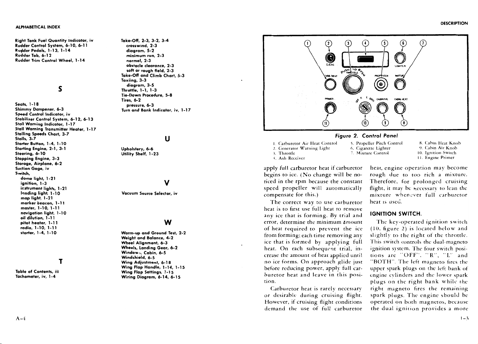
Figure
2.
control
Panet
Starter
Button,
1-4,
1-10
I
Carburetor Air
Heat
Control
5.
Propeller
Pitch
Control 8.
Cabin
Heat Knob
Starting Engine, 2-1,
3-1
Upholstery,
6-6
2.
Generator
Warning
Light
6.
Cigarette
Lighter
9.
Cabin Air
Knob
Steering,
6-10
Utility
Shelf,
1-23
3. Throttle
7.
Mixture
Control
10.
Ignition Switch
Stopping Engine,
3-3 4. Ash
Receiver
i1. Engine Primer
Storage, Airplane,
6-2
Suction
Gage, iv apply
full
carburetor
heat if carburetor heat,
engine oper2tion may become
Switch,
begins to
ice.
(No change
will be
no-
rough
due
to too
rich a
mixture.
dome
light,
1-21
-
ignition,
1-3
ticed in
the rpm
because
the constant
Therefore,
for
prolonged
cruising
instrument lights,
1-21
speed
propeller
will
automatically night,it
may be
necessary
to lean
the
Innding
light,
1-10
Vacuum
Source
Selector,
iv
compensate for this.)
mixture
whenever
full
carburetor
map light,
1-21
marker
beacon,
1-11
The
correct
way
to use carburetor
heat is
used.
master, 1-10,
1-11
heat is to first use full heat to
remove
v
tn light,
1-10
any
ice that is
forming.
By
trial and
IGNITION
SWITCH.
pitot
heater,
1-11
W
error,
determine the minimum amount
The
key-operated
ignition switch
radio,
1-10,
1-11
of heat required
to
prevent
the
ice (10,
figure
2) is located below and
starter,
1-4,
1-10
WWgmht nadnd Ground
Te2st,
2-2
from
forming; each time removing any
slightly to the
right of
the throttle.
Wheel Alignment,
6-3
ice that is formed
by applying
full
This
switch controls
the
dual-magneto
Wheels, Landing
Gear,
6-2
heat. On
each
subsequent
trial,
in-
ignition system.
The four switch
posi-
h
abi5n,
6-5
crease the amount
of
heat
applied
until tions
are
"OFF",
"
R",
"L and
T Wing
Adjustment,
6-18
no ice forms. On approach glide
just "BOTH". The left
magneto
Sres the
Wing Flap
Handle,
1-14,
1-15
before
reducing
power,
apply
full
car-
upper
spark
plugs on
the left bank of
Table
of Contents, m
Wing
Flap Settings,
1-15
-
Tachometer,
iv,
1-4
Wiring Diagram,
6-14,
6-15
buretor heat
and
leave in
this
posi-
engine cylinders and
the
lower spark
tion.
plugs
on the right bank while the
Carburetor heat is rarely
necessary
right
magneto fires
the remaining
or desirable during cruising
night. spark
plugs.
The engine should be
However,
if
cruising
nightconditions operated on both magnetos, because
demand the use of
full
carburetor
the dual ignition provides
a more
DESCRIPTION
ALPHABETICALINDEX
complete
burning
of the
fuel-air
mix-
that
the engine
be turned
over
L O
ture driving the pistons. The
"R"
and
while priming.
It may be
nec-
Landing,
2-5,
3-7
Oil
Dilution
System,
3-9
L"
positions are used for
checking
essary
to continue
priming
crosswind,
2.5
switch,
1-11
purposes only.
until the engine runs
smoothly.
diagram,
5.6
Oil Filler
Cap,
1-6
normal,
2-5 Oli
Level,
1-6
ENGINE PRIMER.
STARTER
BUTTON.
short
field,
2-5
Oil Pressure Gage, iv,
1-8
Landing
Gear, 1-15,
6-2
Oil Specification and
Grade,
1-8
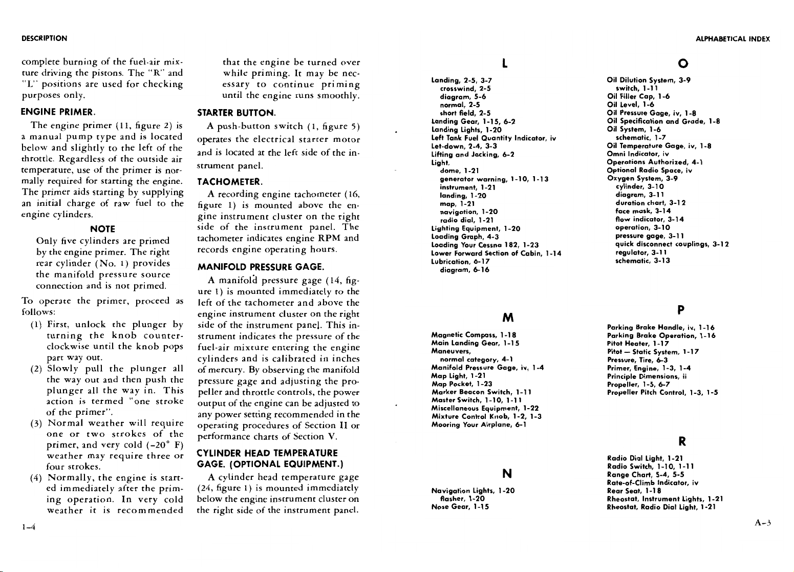
The engine primer (11,
figure 2)
is
A
push-button
switch
(1, figure
5)
Landing
Lights,
1-20
Oil
System,
1-6
a
manual
pump
type
and
is
located
operates
the
electrical starter motor
Left Tank
Fuel
Quantity Indicator,
iv
schematic,
1-7
below
and
slightly
to
the
left of
the
. .
.
Let-down,
2-4,
3-3
Oil Temperature Gage,
iv,
1-8
.
and is located at the
left
sideofthe
in-
Lifting and
Jacking,
6-2
Omm
Indicator,
iv
throttle.
Regardless
of the outside air
Light
Operations
Authorized,
4-1
temperature, use of
the
primer is
nor-
strument panel
dome,
i-2i
optionalRadio space, iv
mally
required
for
starting the
engine.
TACHOMETER.
(*|*
or
ning, 1-io,
1-13
OxcyÃ
dSys m,
3-9
The
primer aids
starting by
supplying
A
recording
engine
tachometer (16,
landing,
1-2o
diagram,
a-il
an
initial
charge of
raw fuel to the
figure 1)
is mounted
above the
en-
map,
1-21
duration
chart,
3-12
navigation,
1-20 face
mask,
3-14
engine
cylinders-
gine
instrument
cluster on the
right
radio dial,
1-21 flow
indicator,
3-14
NOTE
side of
the
instrument panel.
The
Lighting
Eguipment,
1-20
operation,
3-10
Only
five
cylinders are
primed
tachometer indicates engine RPM and
a ra¢ce
sna 182,
i-2a
9pru
scoangn
c couplings,
a-i2
by
the
engine primer. The
right
records
engine operating hours.
Lower
Forward
Section of
Cabin,
1-14
regulator,
3-11
rear
cylinder
(No.
1) provides
MANIFOLD PRESSURE
GAGE.
Lubricartion, b167
schematic,
3-13
the
manifold pressure source
A
manifold pressure gage
(14,
fig-
connection
and is not primed. . .
.
ure
1) is
mounted
immediately to the
To
operate the primer, proceed
as
left of
the
tachometer and above
the
follows:
engine
instrument
cluster on
the
right
M
(1)
First,
unlock
the plunger
by
side of
the
instrument panel.
This
in-
Parking
Brake
Handle, iv,
1-16
turning
the knob
counter-
strument
indicates
the
pressure
of
the
Magnetic Compass,
1-18
Parking
Brake Operation,
1-16
-
Main
Landing Gear,
1-15
Pitot
Heater,
1-17
clockwise until the knob pops
fuel-air
mixture
entering the
engine
Maneuvers,
Pitot-Static System,
1-17
part
way
out-
cylinders andiscalibrated in
inches
normal
category,
4-1
Pressure,
Tire,
6-3
(2) Slowly
pull the
plunger all
of mercury. By
observing
the manifold
Manifold Pressure
Gage, iv,
1-4
Primer, Engine,
1-3,
1-4
Map Light,
1-21
Principle Dimensions,
n
the
way
out and then
push the
pressure gage
and
adjusting the
pro-
Map
Pocket,
1-23
Propeller,
1-5,
6-7
plunger all the
way
in.
This
peller
and
throttle
controls, the
power
Marker
Beacon
Switch,
1-11
Propeller
Pitch Control,
1-3,
1-5
action
is
termed "one
stroke
out ut
of the en
ine
can be adjusted to
Master
Switch,
1-10,
1-11
Miscellaneous
Equipment,
1-22
of the
primer"-
any
power
setting
recommended in the
Mixture control
Knob,
1-2,
1-3
(3)
Normal weather
will require
operating
procedures of Section
II
or
Mooring
Your
Airplane,
6-1
one
or two strokes
of the
performance charts of Section V.
primer,
and very cold
(-20°
F)
weather
may require
three
or
CYLINDER
HEAD
TEMPERATURE
Radio
Dial
Light,
1-21
four
strokes.
GAGE.
(OPTIONAL
EQUIPMENT.)
Radio
Switch,
1-10,
1-11
(4)
Normally,
the
engine
is
start-
A
cylinder
head
temperature
gage
N
ns.c
,b
5a
ed
immediately
after the
prim-
(24, figure
1)
is mounted immediately
Navigation Lights,
1-20
Rear
Seat,
1-18
ing
operation.
In
very cold
below the
engine instrument
cluster
on
nasher,
1-20
Rheostat,
Instrument Lights,
1-21
weather
it is
recommended
the right side of
the
instrument
panel.
Nose
Gear,
1-15
Rheostat,
Radio Dial Light,
1-21
A-3
1-4

ALPHABETICAL
INDEX DESCRIPTION
E
Gyro Horizon,
iv
The
gage
is
calibrated in
degrees
stant speed
feature
enables your
en-
Ground
Service Plug,
1-12,
6-14
Fahrenheit
and
is
electrically
operated. gine to
deliver
uniform
horsepower
Electrical
System,
1-11
However,
its sole
source of power
is
for each
throttle
setting.
control panel,
iv,
1-10,
1-11
schematic,
1-12
a thermocouple mounted
under
the
PROPELLERPITCH
CONTROL.
wiring diagram,
6-14,
6-15
lower
spark
plug of
the
left
rear en
The control
knob
(5,
figure
2)
to
Ele a r
Control
System,
6-12
H
gine cylinder and thus the
instrument
the right
of
the
throttle controls the
before
starting,
2-1,
3-1
Headphone Jack, iv
requires no power from the
electrical
engine speed. With
the
control
full
comraa nn
t
i6ons,
4-2
Heating
System, 1-18,
1-19
system. By
observing
the
gage
read-
forward, the
propeller
is in high
rpm
operating
procedure,
3-1
ings and
adjusting
the power
setting
position. It is moved
through its
com-
primer, 1-3,
1-4
the pilot can keep the engine
temper-
plete range by
pressing in the control
starting,
2-1,
3-1
atures
within
operating
limitations
lock
button in the
center of the
knob
stoppmg,
3-3
warm-up,
2-2,
3-2
PROPELLER.
and
pulling
out
the control
knob
to
Exterior Inspection
Diagram,
1-24
A
constant speed
propeller
is
stand.
its full
out or low
rpm position. For
Ignition
Switch,
1-3
ard
equipment
on
your
airplane, and
sensitive
control,
the
control
knob
,at,°,ia,
¡,
provides
your
airplane
with
maximum
can
be
screwed in
or out by turning
azimuth,
iv
performance
at
take-off,
during
climb,
the knob
with
the thumb
lock
in
its
F
Ieft tank
fuel
quantity,
iv
and
while cruising.
normal
locking position.
g
a u I uantity,
iv
A
propeller with
low
blade
angles
In use,
the
recommended procedure
Flap
BCel
k
Adjustment,6
speed
control,
iv
gives the
best performance
for
take-off
is
to
move
the
control full forward
Flight Control
System, 1-13,
6-7
stall
warning,
1-17
and
climb,
while
a
propeller with
high
(high rpm)
for
taxiing
and
take-off.
Front
Seats,
1-18
Insp
n ann
1 r,
270
blade
angles is more adapted
to
high
After
take-off
and
climb,
screw out
FF
nea
i
ta n u
,
1-10
Inspection Service and inspection
Period,
6-19
speed and
high
altitude
flying.
propeller
control
to the desired
cruis-
Fuel
Quantity
Indicators, iv,
1-11
Instruments,
1-16
A fixed-pitch
propeller
ordinarily
is
ing
rpm. When
changing
rpm
settings
Fuel
Selector Valve,
1-8
'I t a n
,
-2
set
to
obtain
best
performance
while
during cruising flight, it is
recom-
SStrean
at
a n dn
ve 1-80
Instrument
Panel,
iv
the
airplane
is cruising, consequently
mended that
control be moved by
Fuel System,
1-8
Internal
Cabin Measurements,
6-2s
the
take-off
and
climb
characteristics
screwing
in or
out since a small
move-
schematic,
1-9
are not at their best. The constant
ment of the
control
will
cause
a
con-
el
Taankk
Sump
Drain
Plugs,
1-lo
speed
propeller will
permit
low blade
siderable
change in rpm.
angles
for
take-off
and
climb, thereby
Propeller
surging
(rpm
variation up
.!
giving optimum performance.
After
CONTROL
LOCK BUTTON
Jacking and Lifting,
6-2
the
airplane
has
reached
its
proper
altitude
and has
leveled
off,
the
pro-
G
peller
can be
changed
to
a
higher
Gage,
blade
angle
and thus provide
the
de-
carburetor air temperature, iv
sired
cruising
performance.
cylinder head temperature, iv,
1-4
The propeller is controlled
by
a
manifold
pressure,
iv,
1-4
.
oil
pressure,
iv,
1-8
Knob
governor
which
automatically changes
'
LOW RPM
HIGH RPM
oil
temperature,
iv,
1-8
cabin
air,
1-3
the
pitch
of
the propeller
to
counter-
suction,
iv
cabin
heat,
1-3
act
any
tendency
of the engine
to vary
Generator
Warning
Light, 1-3,
1-10,
1-13
carburetor
air heat
control, 1-2,
1-3
Glove Compartment,
iv,
1-23
fuel strainer
drain, iv,
1-lo
from
the
rpm
setting established
by
PROPELLER
PITCH CONTROL
Ground Handling,
6-1
mixture
control,
1-2,
1-3
the propeller
pitch control.
This
con-
A-2
I-5

DESCRIPTION
and down several times
before
engine
opening the
2ccess
door
on
the
left
ALPHABETICAL INDEX
smooths out and becomes steady) can side of
the engine
cowl
and
re2ding
be prevented
by smooth throttle
and
the oil
level
on the
dipstick, located
propeller
control
operation.
Do not
just
aft of the left rear
engine cylinder.
change
throttle and propeller
controlset-
The
dip
stick
incorporates
2
spring
cessnaService
Publications,
6-26
rings with
jerky
and rapid
motions.
lock which prevents
it
from
working
cigarette
Lighter,
1-3,
1-22
loose in
flight.
The dip
stick
can
be
Adjustable
Stabilizer
Control Wheel,
1-13
Circuit
Breakers, 1-11,
1-13
NOTE
removed
by rotating it
until
the spring
After
Landing,
2-5
Check
List,
2-1
If
the
engine power
and rpm
lock is
disengaged and
pulling
the dip
AAil
o
rran
de
6
-6
9
Clea
nn
um
surfaces,
6-5
are to be increased,
increase
the
stick
up
and
out.
When
replacing
the
Airplane
File,
6-18
battery,
6-4
propeller
control
first
and
then
dip
stick,
m2ke
sure
th2t
the spring
Airspeed Correction
Table,
5-1
carburetor air
filter,
6-6
the
throttle.
If
power and rpm
lock
is engaged.
AArspeedd
Ln
taa't
ns
4-1
enDgine compartment,
6-6
are
to be decreased,
reduce
the
To obtain
correct
oil
level
readings, Altimeter,
iv
tires,
6-3
throttle first
and
then
the
pro-
it is import2nt
that
the
engine
be
shut
Aluminum
Surfaces,
6-5
upholstery,
6-6
peller
control. In this
manner,
down
at least
5
to 10
minutes prior
to
g¡,
Sce ers,
1-3,
1-23
dh
d
65-5
excessive
cylinder
pressures
the oil check.
This
permits
the
engine
Assist
straps,
1-22
clearingthe Propeller,
3-1
will be
avoided.
oil to drain out
of the
engine oil
pas-
Azimuth Indicator,
iv
Climkb,
2-4 -62,
3-4
s2ges
into
the
oil sump
giving
a
more
coatHanger Hook,
1-23
OIL SYSTEM.
2ccur2te
oil
level
reading.
Cold Weather Operation,
3-8
Compass Card Holder, iv
The Continental
0-470-L
engine
has
NOTE control,
a
wet
sump
oil
system which
utilizes
Oil should
be
2dded
if
below
ad ta rle
stabilizer,
1-13
the engine
pan
as
an oil tank. Other
nine
quarts
and
should
be
full
saggage
compartment,
1-23
cabin heater,
1-3
major components of the
system
are
if
an extended
flight
is planned.
Battery,
6-4
carburetar air
heat,
1-2,
1-3
an
engine-driven
oil
pump
2nd an oil
.
.
.
Befav Entering
Airplane,
2-1
mixture,
1-2,
1-3
- The
oil
filler
cap
is
made accessible
Before Landin
2-4
panel,
1-3
cooler
mtegrally mounted on the
en-
s'
rk brak
by opening the access door
on
the
Befo;e
starting
Engine,
2-1,
3-1
pa ing e,
iv
gin
1
temperature is regulated
auto-
top of the engine
cowl. In repl2cing
Bef
te ke-Off,
2-3
propdell pitc1h,
14-3
.
. the
oil
filler
cap, make
sure that it
is
Brake Pedais,
1-16
wheels,
1-13
matically
in this
system
by a
thermo-
on
firmly
and
turned
clockwise
2s
far
Brake System,
1-16
Cross Country Service,
6-26
statically
controlled oil cooler. The Cruise,
3-2,
3-6
as it will
go
to prevent loss of oil thru
Cruisin
,
2-4
thermostat shuts
off the passage of
oil
9
. the
filler
neck.
cylinder
Head Temperature
Gage,
iv,
1-4
through
the
cooler whenever the oil
temperatures
are below
150°
F.
Ordi-
OIL SPECIFICATION AND GRADE.
narily, the
oil
cooler is
adequate to
Aviation grade
oil is recommended
keep
oil
temperatures well
within the
for your airplane and
should be
Cabin
Air Knob,
1-3
normal operating
range
as indicated
changed
every
25 hours of oper2tion
cabinAir
Temperature
Control
System,
1-18
D
by
the green
arc
on the
oil
tempera.
When
adding
or changing
oil, use
the
diagram,
1-19
ture
indicator.
gr2des
in
the
following
table:
cabin
Doors,
1-22
Dip
Stick,
1-6
Cabin
Heat
Knob,
1-3
Directional
Gyro,
iv
OIL LEVEL.
Average Outside
Recommended
cabinVentilators,
1-20
Dome
Light,
1-21
The oil c2pacity
of the
Continent21
Temperature OH
Grade
r Hec
2Co
ol,
1-2,
1-3
Drain Plu
,sump,
1-10
0-470-L
engine
is twelve quarts. The
Below
40°
F. SAE
30
carburetor
Air
Temperature
Gage,
iv
fuel
line,
1-10
quantity
can
be
checked
e2sily by
Above
40°
F. SAE
50
center
of
Gravity
Envelope,
4-3
oil
sump,
1-7
1-6
A--I

CARE-RESPONSIBILITIES
DESCRIPTION
THERMOSTAT
Sales a Seruite
PROPELLER
CONTROL
.
OIL
COOLER
PHOPELLER
(THERMOSTAT
OPEN)
CROSS
COUNTRY
SERVICE
'*,
THERMOSTAT
On
your cross
country
travels
makeita point to
stop at a
Cessna
*-
°1HLEC
service
station
for your service
requirements.
Your Dealer will be
PROPELLER
CLOSED)
glad to
supply
you with
a copyofa
current
service station list, or if
GOVERNOR
you wish,
you
may write to the Service Department, Cessna Aircraft
Company,
Wichita, Kansas,
asking
for it and
it
will
be
promptly
mailed
to you.
°'LLE
CAP
CESSNA SERVICE
PUBLICATIONS
I
a
The
Cessna
Aircraft
Company
publishes
and
revises,
as necessarv.
1.
O
OIL
OIL
PRESSURE
TEMPERATURE
Manuals,
Parts
Catalogs,
Service Letters
and Service News LetterS. GAGE
GAGE
This
material
goes to all
authorized
Cessna
Service
Stations so that
they
have the
latest
authoritative information
for
servicing
your
Cessna.
Your Cessna
Dealer
has
an owner
follow-up
system
to
notify
you
sue
on
when he
receives
information that applies
to
your Cessna.
In
addi
SCREEN
- -
-
OIL DIP
STICK
tion. if you wish, you
may
choose
to
receive
similar
not16cation
directly
from
the Cessna
Service
Department. A subscation card
DR
LIN
UG
is supplied
to
you in
your
airplane file for your
use,
should
you
FUEL
LINE
eboose to request
this service. Your
Cessna
Dealer will
be
glad to
',"°uMOOINL
OISLCRFIELENER
wpply you
with
details
concerning these follow-up
programs,
and
SOLENOID
stands
ready
through
his
Service
Department
to
supply you with
fast,
efficient,
low
cost service.
ENGINE
SUMP
ENGINE
PRESSURE
-
OIL
PUMP
RELIEF VALVE
ENGINE
OIL
Figure3.Oil
System Schematic
6-26
1--7

DESCRIPTION
CARE
-
RESPONSIBILITIES
NOTE
ing air
by a
filter screen located in the
During
oil
changes, remove and
air scoop. Proper
cleaning
and
servic-
clean oil filter screen
located
ing
of
this air filter is important to
Cabin (floor) Lengths:
.
. .
increase life
and maintain
top
efTi-
ynow
to
NOTE
on
the right sideofthe
engine
.
Measurements
are with
accessory
section.
ciency of
the
engine. The
filter
should .
. .
. . -
43 in
co-pilot seat,
rear
seat,
be
serviced every
25
hours
(during
- - -
21 in
and
baggage
compartment
OIL
TEMPERATURE GAGE-
regular oil
change)
or oftener
when
mh
o
abl
A capillary
type,
oil temperature
operating
in
dusty
conditions.
Under
27 in-
and
saving 40
lbs
on
emp-
gage (15, figure
1) is
mounted
within
extremely
dusty
conditions,
daily
the
engine instrument
cluster on
the maintenance
of
the
air filter
is
recom-
right
side of the
instrument
panel.
A
mended. Refer to
the
servicing
in-
green arc on
the
gage dial indicates
structions stamped
on
the
carburetor
'
the
normal operating range of
oil
air filter for the servicing
procedure
temperatures. Refer to
Section
IV
for
to
be used.
instrument markings.
OIL
PRESSURE
GAGE.
FUEL
SYSTEM.
An
oil
pressure gage
(12, figure
1)
Fuelissupplied
to the engine
from
is
mounted within
the engine
instru-
two
rubberized,
bladder-type
fuel
ment cluster on
the right side of the
cells,
one located in each wing.
From
instrument panel. The gage is
cali-
these tanks, fuel is
gravity-fed
through
cabin(floor)
Widths:
brated
in pounds per
square inch.
a
fuel
selector valve and fuel
strainer
Refer to Section
IV
for
instrument
to
the
engine carburetor.
(i)
/
Cabin
Volume:
.
Point
Tunnel
to
Side Wall
.
.
-
15
1/2 in.
55 Cubic
feet
markmgs
unobstructed.
FUELSPECIFICATION
AND
GRADE•
Rear
Lineofpilot's
AIR INDUCTION
SYSTEM.
Aviation grade
fuel
should
always
Seat-Wall
to
Wall. .
.
.
. .36 tn.
Air is
ducted to the
carburetor from
be used except
under emergency
con- (Ï)^ft
Door Post Bulkhead .
.
. 31 in.
an air
scoop
located on the bottom of ditions.
The recommended
fuel is
80
(i)
Aft
Section Bulkhead
. . . . .30
in.
D
00
R WID
I
HS
the engine
cowl.
Dirt and
other
for-
octane
minimum
rating.
Highly
lead-
(i)
Rear
wan-or
saggage
eign matter is
filtered from the
incom-
ed
fuels are not recommended.
Compartment
-
-
30
in.
Cabin
Heights:
40 36
nwho
FUEL
QUANTITY DATA
(U.
S. GALLONS).
^2
-
.48
inches
i
n
uw)ws
.
. .
. . .
46
inches
ADDITIONAL
TOTAL
-
-
45 inches
TANKS
NO
UASLALFLLE
FUHEL
UFSOARBLLEE
LEL
UNFUUSEABLE
V
ME
. . .
. .
40 inches
CONDITIONS
FLIGHTONLY EACH
.
. . .
. -
21
inches
LEFT
WING l
27.5
gal.
3.5
gal.
1.5
gal.
32.5
RIGHT
WING 1
27.5
gal.
3.5
gal. 1.5 gal.
32.5
---
INTERNAL
CABIN
ME
ASUREMENT
1-8
6-25

CARE
-
RESPONSIBILITIES
DESCRIPTION
fuselage
attachment. If
necessary,
tighten
landing
gear
bolts
and
wedges. With airplane
in normal
position on
the
floor
visually
inspect
FUEL
QUANTITY
INDICATORS
landing
gear
spring leaf for
cracks.
(Remove
landing
gear wheels and
pack with grease at
first
100
hours and
every
500 hours
thereafter
un-
LEFT
RIGHT
less otherwise
designated
by
owner.)
2. Operate brakes and feel
for
sponginess. Bleed,
and
refill
brake system
if necessary.
Check brake
linings
for wear within permisssible
limitS.
LEFT WING TANK
RIGHT WING
TANK
3. Set
parking brake and
check exposed
lines and hoses for deterioration
and evidence of leakage of
hydraulic fluid.
4.
Examine tires
for
proper
inflation, wear,
cuts and blisters. Uneven or
excessive wear
may
indicate need
for
re-alignment of
wheels.
IX. Electrical System.
1. Check
electrical
system by
operating
the lights,
starter,
and
all
acces-
sories which
are incorporated
in the
electrical system.
SUMP
TA SUMP
X.
Visual Check for Exterior
Surfaces.
1. Clean exposed surfaces
FUEL SELECTOR
2. Check:
VALVE
a. Condition
of
exposed
aluminum surfaces.
b,
Airspeed static source
holes
on each
side
of
fuselage
for stoppage
ENGINE PRIMER
FUEL LINE
c.
Evidence of
leaking
fuel or oil-determine
cause.
DRAIN PLUG
d.
Condition of
decorative
paint
and
all
markings.
XI.
Recowl the engine and
install propeller spinner.
Replace all inspection
plates,
fairings and
seats.
FUEL STRAINER
XII.
Run
engine as in
preliminary run-up
to
check for ignition
drop,
gener-
É
cTO
EN ES
ator
charging rate, oil pressure,
smoothness,
and general operation
of
en-
gine,
propeller,
controls,
and indicatorS. FUEL
STRAINER
DRAIN VALVE
CARBURETOR
i
ggggg i
co en
THROTTLE
VENT
TO
ENGINE
FUEL
CYLINDERS
-FUEL
SYSTEM
g
Figure
4.
6-24
I-9
 Loading...