

Cessna skylance tc T182T Information Manual

CESSNA INTRODUCTION
MODEL T182T NAV III
GFC 700 AFCS
NOTICE
AT THE TIME OF ISSUANCE, THIS INFORMATION
MANUAL WAS AN EXACT DUPLICATE OF THE
OFFICIAL PILOT’S OPERATING HANDBOOK AND
FAA APPROVED AIRPLANE FLIGHT MANUAL AND
IS TO BE USED FOR GENERAL PURPOSES ONLY.
IT WILL NOT BE KEPT CURRENT AND,
THEREFORE, CANNOT BE USED AS A
SUBSTITUTE FOR THE OFFICIAL PILOT’S
OPERATING HANDBOOK AND FAA APPROVED
AIRPLANE FLIGHT MANUAL INTENDED FOR
OPERATION OF THE AIRPLANE.
THE PILOT’S OPERATING HANDBOOK MUST BE
CARRIED IN THE AIRPLANE AND AVAILABLE TO
THE PILOT AT ALL TIMES.
Cessna Aircraft Company
Original Issue - 27 October 2006
Revision 1 - 20 December 2007
U.S.
iRevision 1

INTRODUCTION CESSNA
MODEL T182T NAV III
GFC 700 AFCS
PERFORMANCE - SPECIFICATIONS
*SPEED:
Maximum at 20,000 Feet. . . . . . . . . . . . . . . . . . . . . . . . 176 KNOTS
Cruise, 88% Power at 12,500 Feet . . . . . . . . . . . . . . . . 159 KNOTS
Cruise, 75% Power at 20,000 Feet . . . . . . . . . . . . . . . . 158 KNOTS
Cruise, 75% Power at 10,000 Feet . . . . . . . . . . . . . . . . 145 KNOTS
CRUISE: Recommended lean mixture with fuel allowance for engine
start, taxi, takeoff, climb and 45 minutes reserve.
88% Power at 12,500 Feet . . . . . . . . . . . . . . . . . . .Range - 615 NM
87 Gallons Usable Fuel . . . . . . . . . . . . . . . . . . . Time - 4.0 HOURS
75% Power at 20,000 Feet . . . . . . . . . . . . . . . . . . .Range - 753 NM
87 Gallons Usable Fuel . . . . . . . . . . . . . . . . . . . Time - 4.9 HOURS
75% Power at 10,000 Feet . . . . . . . . . . . . . . . . . . .Range - 721 NM
87 Gallons Usable Fuel . . . . . . . . . . . . . . . . . . . Time - 5.1 HOURS
Max Range at 20,000 Feet . . . . . . . . . . . . . . . . . . .Range - 940 NM
87 Gallons Usable Fuel . . . . . . . . . . . . . . . . . . . Time - 8.6 HOURS
Max Range at 10,000 Feet . . . . . . . . . . . . . . . . . . .Range - 971 NM
87 Gallons Usable Fuel . . . . . . . . . . . . . . . . . . . Time - 8.9 HOURS
RATE OF CLIMB AT SEA LEVEL:. . . . . . . . . . . . . . . . . . . . .1040 FPM
MAXIMUM OPERATING ALTITUDE:. . . . . . . . . . . . . . . . 20,000 FEET
TAKEOFF PERFORMANCE:
Ground Roll . . . . . . . . . . . . . . . . . . . . . . . . . . . . . . . . . . . .775 FEET
Total Distance Over 50 Foot Obstacle. . . . . . . . . . . . . . . 1385 FEET
LANDING PERFORMANCE:
Ground Roll . . . . . . . . . . . . . . . . . . . . . . . . . . . . . . . . . . . .590 FEET
Total Distance Over 50 Foot Obstacle. . . . . . . . . . . . . . . 1350 FEET
STALL SPEED (KCAS):
Flaps Up, Power Idle . . . . . . . . . . . . . . . . . . . . . . . . . . . . . .54 KCAS
Flaps FULL, Power Idle . . . . . . . . . . . . . . . . . . . . . . . . . . .49 KCAS
(Continued Next Page)
ii
U.S.
Revision 1

CESSNA INTRODUCTION
NOTE
MODEL T182T NAV III
GFC 700 AFCS
PERFORMANCE - SPECIFICATIONS (Continued)
MAXIMUM WEIGHT:
Ramp. . . . . . . . . . . . . . . . . . . . . . . . . . . . . . . . . . . . . 3112 POUNDS
Takeoff. . . . . . . . . . . . . . . . . . . . . . . . . . . . . . . . . . . . 3100 POUNDS
Landing . . . . . . . . . . . . . . . . . . . . . . . . . . . . . . . . . . . 2950 POUNDS
STANDARD EMPTY WEIGHT. . . . . . . . . . . . . . . . . . . . 2029 POUNDS
MAXIMUM USEFUL LOAD . . . . . . . . . . . . . . . . . . . . . . 1083 POUNDS
BAGGAGE ALLOWANCE . . . . . . . . . . . . . . . . . . . . . . . . 200 POUNDS
WING LOADING . . . . . . . . . . . . . . . . . . . . . . . . . . . . . . . 17.8 lbs/sq. ft.
POWER LOADING . . . . . . . . . . . . . . . . . . . . . . . . . . . . . . . 13.2 lbs/HP
FUEL CAPACITY. . . . . . . . . . . . . . . . . . . . . . . . . . . . . . . . . . . . 92 GAL
OIL CAPACITY . . . . . . . . . . . . . . . . . . . . . . . . . . . . . . . . . . 9 QUARTS
ENGINE: Textron Lycoming. . . . . . . . . . . . . . . . . . . . . . TIO-540-AK1A
235 BHP at 2400 RPM
PROPELLER: 3-Bladed, Const ant Speed, Diameter. . . . . . 79 INCHES
* Speed performa nce and range are shown for an airplane
equipped with the st andard wheel a nd brake f airings. These
fairings increase the speeds approximately 3 knots over an
airplane without the fairings.
The above performance figures are based on the indicated weights,
standard atmospheric conditions, level, hard-surface dry runways and
no wind. They are calculated values derived from flight tests conducted
by Cessna Aircraft Company under carefully documented conditions
and will vary with individual airplanes and numerous factors affecting
flight performance.
U.S.
iii/ivRevision 1


CESSNA INTRODUCTION
MODEL T182T NAV III
GFC 700 AFCS
Cessna Aircraft Company
NAV III AVIONICS OPTION - GFC 700 AFCS
Serials T18208665 and T18208669 and On
THIS MANUAL INCORPORATES INFORMATION ISSUED IN THE
PILOT'S OPERATING HANDBOOK AND FAA APPROVED
AIRPLANE FLIGHT MANUAL AT REVISION 1, DATED 20
DECEMBER 2007 (PART NUMBER T182TPHBUS-01).
COPYRIGHT © 2006
CESSNA AIRCRAFT COMPANY
WICHITA, KANSAS USA T182TIMBUS-01
Model T182T
U.S.
v/viRevision 1


CESSNA INTRODUCTION
MODEL T182T NAV III
GFC 700 AFCS
TABLE OF CONTENTS
SECTION
GENERAL . . . . . . . . . . . . . . . . . . . . . . . . . . . . . . . . . . . . . . . . . . . . . . 1
LIMITATIONS. . . . . . . . . . . . . . . . . . . . . . . . . . . . . . . . . . . . . . . . . . . . 2
EMERGENCY PROCEDURES . . . . . . . . . . . . . . . . . . . . . . . . . . . . . . 3
NORMAL PROCEDURES. . . . . . . . . . . . . . . . . . . . . . . . . . . . . . . . . . 4
PERFORMANCE. . . . . . . . . . . . . . . . . . . . . . . . . . . . . . . . . . . . . . . . . 5
WEIGHT AND BALANCE/EQUIPMENT LIST. . . . . . . . . . . . . . . . . . . 6
AIRPLANE AND SYSTEMS DESCRIPTION. . . . . . . . . . . . . . . . . . . . 7
HANDLING, SERVICE AND MAINTENANCE . . . . . . . . . . . . . . . . . . . 8
SUPPLEMENTS . . . . . . . . . . . . . . . . . . . . . . . . . . . . . . . . . . . . . . . . . 9
U.S.
vii/viiiRevision 1


CESSNA SECTION 1
MODEL T182T NAV III GENERAL
GFC 700 AFCS
GENERAL
TABLE OF CONTENTS
Page
Three View - Normal Ground Attitude . . . . . . . . . . . . . . . . . . . . . . . .1-3
Introduction . . . . . . . . . . . . . . . . . . . . . . . . . . . . . . . . . . . . . . . . . . . .1-5
Descriptive Data . . . . . . . . . . . . . . . . . . . . . . . . . . . . . . . . . . . . . . . .1-5
Engine. . . . . . . . . . . . . . . . . . . . . . . . . . . . . . . . . . . . . . . . . . . . . .1-5
Propeller . . . . . . . . . . . . . . . . . . . . . . . . . . . . . . . . . . . . . . . . . . . .1-5
Fuel . . . . . . . . . . . . . . . . . . . . . . . . . . . . . . . . . . . . . . . . . . . . . . . .1-6
Fuel Capacity . . . . . . . . . . . . . . . . . . . . . . . . . . . . . . . . . . . . . . . .1-6
Oil . . . . . . . . . . . . . . . . . . . . . . . . . . . . . . . . . . . . . . . . . . . . . . . . .1-7
Oil Sp ecification. . . . . . . . . . . . . . . . . . . . . . . . . . . . . . . . . . . . . . .1-7
Oil Capacity. . . . . . . . . . . . . . . . . . . . . . . . . . . . . . . . . . . . . . . . . .1-7
Maximum Certificated Weights . . . . . . . . . . . . . . . . . . . . . . . . . . .1-8
Weight In Baggage Compartment - Normal Category. . . . . . . . . .1-8
Standard Airplane Weights . . . . . . . . . . . . . . . . . . . . . . . . . . . . . .1-8
Cabin And Entry Dimensions . . . . . . . . . . . . . . . . . . . . . . . . . . . .1-8
Baggage Space And Entry Dimensions . . . . . . . . . . . . . . . . . . . .1-8
Specific Loadings . . . . . . . . . . . . . . . . . . . . . . . . . . . . . . . . . . . . .1-8
Symbols, Abbreviations And Terminology . . . . . . . . . . . . . . . . . . . . .1-9
General Airspeed Terminology And Symbols . . . . . . . . . . . . . . . .1-9
Meteorological Terminology . . . . . . . . . . . . . . . . . . . . . . . . . . . .1-10
Engine Power Terminology . . . . . . . . . . . . . . . . . . . . . . . . . . . . .1-10
Airplane Performance And Flight Planning Terminology. . . . . . .1-12
Weight And Balance Terminology . . . . . . . . . . . . . . . . . . . . . . . .1-13
Metric/Imperial/U.S. Conversion Charts. . . . . . . . . . . . . . . . . . . . . .1-15
Weight Conversions . . . . . . . . . . . . . . . . . . . . . . . . . . . . . . . . . .1-16
Length Conversions . . . . . . . . . . . . . . . . . . . . . . . . . . . . . . . . . .1-18
Distance Conversions . . . . . . . . . . . . . . . . . . . . . . . . . . . . . . . . .1-22
Volume Conversions . . . . . . . . . . . . . . . . . . . . . . . . . . . . . . . . . .1-23
Temperature Conversions. . . . . . . . . . . . . . . . . . . . . . . . . . . . . .1-26
Pressure Conversion. . . . . . . . . . . . . . . . . . . . . . . . . . . . . . . . . .1-27
Volume To Weight Conversion . . . . . . . . . . . . . . . . . . . . . . . . . .1-28
Quick Conversions . . . . . . . . . . . . . . . . . . . . . . . . . . . . . . .1-29/1-30
U.S.
1-1/1-2T182TPHBUS-01

CESSNA SECTION 1
MODEL T182T NAV III GENERAL
GFC 700 AFCS
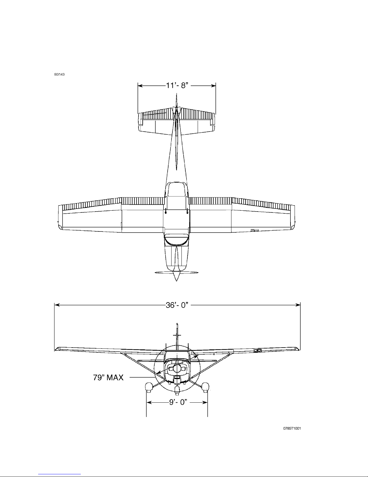
THREE VIEW - NORMAL GROUND ATTITUDE
Figure 1-1 (Sheet 1 of 2)
U.S.
1-3T182TPHBUS-00

SECTION 1 CESSNA
NOTE
GENERAL MODEL T182T NAV III
GFC 700 AFCS
THREE VIEW - NORMAL GROUND ATTITUDE
• Wing span shown with standard strobe lights installed.
• Wheel base length is 66.5 inche s.
• Propeller ground clearance is 10.875 inches.
• Wing area is 174.0 square feet.
• Minimum turning radius (*pivot point to outboard wing
tip) is 27.0 feet.
• Normal ground attitude is shown with nose strut showing
approximately 2 inches of strut, and wings level.
Figure 1-1 (Sheet 2)
1-4
U.S.
T182TPHBUS-00

CESSNA SECTION 1
MODEL T182T NAV III GENERAL
GFC 700 AFCS
INTRODUCTION
This POH co ntains 9 se cti on s, a nd incl ud es the ma ter ial re qu ire d to be
furnished to the pilo t by 14 CFR 23 . It also contai ns supp lemen tal data
supplied by Cessna Aircraft Company.
Section 1 provides basic data and information of general interest. It
also contains definitions or explanations of symbols, abbreviations, and
terminology commonly used.
DESCRIPTIVE DATA
ENGINE
Number of Engines: 1
Engine Manufacturer: Textron Lycoming
Engine Model Number: TIO-540-AK1A
Engine Type:Turbocharged, direct drive, air-cooled, horizontally
opposed, fuel injected, six cylinder engine with 541.5 cu.
in. displacement.
Horsepow er Ratin g and En gine Speed: 235 rated BHP at 32 in.hg. and
2400 RPM
PROPELLER
Propeller Manufacturer: McCauley Propeller Systems
Propeller Model Number: B3D36C442/80VSB-1
Number of Blades: 3
Propeller Diameter: 79 inches
Propeller Type: Constant speed and hydraulically actuated.
(Continued Next Page)
U.S.
1-5T182TPHBUS-01

SECTION 1 CESSNA
WARNING
NOTE
NOTE
GENERAL MODEL T182T NAV III
GFC 700 AFCS
DESCRIPTIVE DATA (Continued)
FUEL
USE OF UNAPPROVED FUELS MAY RESULT IN
DAMAGE TO THE ENGINE AND FUEL SYSTEM
COMPONENTS, RESULTING IN POSSIBLE ENGINE
FAILURE.
Approved Fu el Grad es (an d Col or s):
100LL Grade Aviation Fue l (Blue)
100 Grade Aviation Fue l (Gree n)
Isopropy l alcohol or Di ethylene Glycol Mono methyl Et her
(DiEGME) may be added to the fuel supply. Additive
concentra tion s shall no t e xcee d 1% f or iso pro pyl alco ho l or
0.10% to 0.15% for DiEGME. Refer to Section 8 for
additional infor ma tion .
FUEL CAPACITY
Total Capacity . . . . . . . . . . . . . . . . . . . . . . . . . .92.0 U.S. GALLONS
Total Usable. . . . . . . . . . . . . . . . . . . . . . . . . . . .87.0 U.S. GALLONS
Total Capacity Each Tank . . . . . . . . . . . . . . . . .46.0 U.S. GALLONS
Total Usable Each Tank . . . . . . . . . . . . . . . . . . .43.5 U.S. GALLONS
To ensure maximum fuel capacity and minimize
crossfeeding when refueling, always park the airplane in a
wings level, normal ground attitude and place the fuel
selector in the LEFT or RIGHT position. Refe r to Figure 1-1
for normal ground attitude dimensions.
(Continu ed Next Page)
1-6
U.S.
T182TPHBUS-00

CESSNA SECTION 1
NOTE
MODEL T182T NAV III GENERAL
GFC 700 AFCS
DESCRIPTIVE DATA (Continued)
OIL
OIL SPECIFICATION
MIL-L-22851 or SAE J1899 Aviation Grade Ashless Dispersant Oil: Oil
conforming to Textron Lycoming Service Instruction No 1014, and all
revisions and supplements thereto, must be used.
Recommended viscosity for temperature range:
MIL-L-22851
or SAE J1899
Ashless Dispersant Oil
Temperature
Above 27°C (80°F) 60
Above 16°C (60°F) 40 or 50
-1°C (30°F) to 32°C (90°F) 40
-18°C (0°F) to 21°C (70°F) 30, 40 or 20W-40
Below -12°C (10°F) 30 or 20W-30
-18°C (0°F) to 32°C (90°F) 20W-50 or 15W-50
All Temperatures 15W-50 or 20W-50
SAE Grade
When operating temperatur es overlap, use the lighter
grade of oil.
OIL CAPACITY
Sump. . . . . . . . . . . . . . . . . . . . . . . . . . . . . . . . . . . . 8 U.S. QUARTS
Total. . . . . . . . . . . . . . . . . . . . . . . . . . . . . . . . . . . . . 9 U.S. QUARTS
(Continued Next Page)
U.S.
1-7T182TPHBUS-00

SECTION 1 CESSNA
NOTE
GENERAL MODEL T182T NAV III
GFC 700 AFCS
DESCRIPTIVE DATA (Continued)
MAXIMUM CERTIFICATED WEIGHTS
Ramp Weight . . . . . . . . . . . . . . . . . . . . . . . . . . . . . . . . . 3112 POUNDS
Takeoff Weight . . . . . . . . . . . . . . . . . . . . . . . . . . . . . . . . 3100 POUNDS
Landing Weight . . . . . . . . . . . . . . . . . . . . . . . . . . . . . . .2950 POUNDS
WEIGHT IN BAGGAGE COMPARTMENT, NORMAL CATEGORY
Baggage Area A (Station 82 to 109). . . . . . . . . . . . . . . . .120 POUNDS
. . . . . . . . . . . . . . . . . . . . . . . . . . . . . . . . . . . . . . . . Refer to note below.
Baggage Area B (Station 109 to 124). . . . . . . . . . . . . . . . .80 POUNDS
. . . . . . . . . . . . . . . . . . . . . . . . . . . . . . . . . . . . . . . . Refer to note below
Baggage Area C (Station 124 to 134) . . . . . . . . . . . . . . . .80 POUNDS
. . . . . . . . . . . . . . . . . . . . . . . . . . . . . . . . . . . . . . . . Refer to note below
The maximum allowable combined weight capacity for
baggage in areas A, B and C is 200 pounds. The maximum
allowable weight capacity for baggage in areas B and C is
80 pounds.
STANDARD AIRPLANE WEIGHTS
Standard Empty Weight . . . . . . . . . . . . . . . . . . . . . . . . .2023 POUNDS
Maximum Useful Load, Normal Category . . . . . . . . . . . 1089 POUNDS
CABIN AND ENTRY DIMENSIONS
Detailed dim ensions of the cabin interior a nd entry door op enings are
illustrated in Section 6.
BAGGAGE SPACE AND ENTRY DIMENSIONS
Dimensions of the baggage area and baggage door opening are
illustrated in detail in Section 6.
SPECIFIC LOADINGS
Wing Loading . . . . . . . . . . . . . . . . . . . . . . . . . . . . . . . . . .17.8 lbs/sq. ft.
Power Loading . . . . . . . . . . . . . . . . . . . . . . . . . . . . . . . . . . . 13.2 lbs/hp
1-8
U.S.
T182TPHBUS-00

CESSNA SECTION 1
MODEL T182T NAV III GENERAL
GFC 700 AFCS
SYMBOLS, ABBREVIATIONS AND TERMINOLOGY
GENERAL AIRSPEED TERMINOLOGY AND SYMBOLS
KCAS Knots Calibrated Airspeed is in dicated airs peed correc ted
for position and instrument error and expressed in knots.
Knots calibrated airspeed is equal to KTAS in standard
atmosphere at sea level.
KIAS Knots Indicated Airspeed is the speed shown on the
airspeed indicator and expressed in kn ots.
KTAS Knots True Airspeed is the airspeed expressed in knots
relative to undisturbed air which is KCAS corrected for
altitude and temperature.
V
V
V
V
V
V
A
FE
NO
NE
S
SO
Maneuv ering Sp eed is the maximum speed at which full or
abrupt control movements may be used without
overstressing the airframe.
Maximum Flap Extended Speed is the highest speed
permissible with wing flaps in a prescribed extended
position.
Maximum Structural Cruising Speed is the speed that
should no t be exce eded e xcept in smooth air, then only with
caution.
Never Exceed Speed is the speed limit that may not be
exceeded at any time.
Stalling Speed or th e m in im u m st ead y flight sp eed is the
minimum speed at which the airplane is controllable.
Stalling Speed or th e m in im u m st ead y flight sp eed is the
minimum speed at which the airplane is controllable in the
landing configuration at the most forward center of gravity.
V
x
Best Angle of Climb Speed is the speed which results in the
greatest gain of altitude in a given horizontal distance.
V
Y
Best Rate of Climb Speed is the sp eed which resu lts in the
greatest gain in altitude in a given time.
(Continued Next Page)
U.S.
1-9T182TPHBUS-01

SECTION 1 CESSNA
GENERAL MODEL T182T NAV III
GFC 700 AFCS
SYMBOLS, ABBREVIAT IONS AND TERMINOLOGY
(Continued)
METEOROLOGICAL TERMINOLOGY
OAT Outside Air Temperature is the free air static
temperature. It may be expressed in either degrees
Celsius or deg re es Fahre nh ei t.
Standard
Temperature Standard Temperature is 15°C at sea level pressure
altitude and decreases by 2°C for each 1000 feet of
altitude.
Pressure
Altitude Pressure Altitude is the altitude read from an altimeter
when the altimeter's barometric scale has been set to
29.92 inches o f mercury (1013 mb).
ENGINE POWER TERMINOLOGY
BHP Brake Horsepower is the power developed by the
engine.
RPM Revolutions Per Mi nute is engine speed.
Static
RPM Static RPM is engine speed attain ed durin g a full thr ottle
engine runup when the airplane is on the ground and
stationary.
MP Manifold Pressure is a pressure measured in the
engine's indu ction system and is expr essed in inches of
mercury (in.hg.).
MCP Maximum Continuous Power
(Continu ed Next Page)
1-10
U.S.
T182TPHBUS-00

CESSNA SECTION 1
MODEL T182T NAV III GENERAL
GFC 700 AFCS
SYMBOLS, ABBREVIATIONS AND TERMINOLOGY
(Continued)
ENGINE POWER TERMINOLOGY (Continued)
Lean
Mixture Decreased proportion of fuel in the fuel-air mixture
supplied to the engine. As air density decreases, the
amount of fuel required by the engine decreases for a
given throttle setting. Adjusting the fuel-air mixture to
provide a smaller portion of fuel is known as "leaning" the
mixture.
Rich
Mixture Increased proportion of fuel in the fuel-air mixture
supplied to the engine. As air density increases, the
amount of fuel required by the engine increases for a
given throttle setting. Adjusting the fuel-air mixture to
provide a greater portion of fuel is known as "richening"
the mixture.
Full
Rich Mixture control full forward (pushed in, full control
travel, toward the panel).
Idle
Cutoff Mixture control full aft (pulled out, full control travel,
away from the panel) .
Full
Throttle Throttle full forward (pushed in, full control travel,
toward the panel). Also known as "full open" throttle.
Closed
Throttle Throttle full aft (pulled out, full control travel, away from
the panel). Also known as the throttle "idle" position.
(Continued Next Page)
U.S.
1-11T182TPHBUS-01

SECTION 1 CESSNA
GENERAL MODEL T182T NAV III
GFC 700 AFCS
SYMBOLS, ABBREVIAT IONS AND TERMINOLOGY
(Continued)
AIRPLANE PERFORMANCE AND FLIGHT PLANNING
TERMINOLOGY
Demonstrated
Crosswind
Velocity Demonstrated Crosswind Velocity is the velocity of
the crosswind component for which adequate control
of the airplan e during takeoff and landin g was actual ly
demonstrated during certification tests. The value
shown is not considered to be li miting.
Usable Fuel Usable Fuel is the fuel available for flight planning.
Unusable Fuel Unusable Fuel is the quantity of fu el that can not be
safely used in flight.
GPH Gallons Per Ho ur is the amo un t of fu el con sum ed per
hour.
NMPG Nautical Miles Per Gal lon is the distance which can
be expecte d per gallon of fuel cons umed at a spec ific
engine power setting and/or flight configuration.
g g is acceleration due to gravity.
Course Datum Course Datum is the compass r eference used by the
autopilot, along with course deviation, to provide lateral
control when tracking a navi gation signal.
(Continu ed Next Page)
1-12
U.S.
T182TPHBUS-01

CESSNA SECTION 1
MODEL T182T NAV III GENERAL
GFC 700 AFCS
SYMBOLS, ABBREVIATIONS AND TERMINOLOGY
(Continued)
WEIGHT AND BALANCE TERMINOLOGY
Reference
Datum Reference Datum is an imag inary vertica l plane fr om
which all horizontal distances are measured for
balance pur po ses.
Station Station is a location along the airplane fuselage given
in terms of the distance from the reference datum.
Arm Arm is the horizontal distance from the reference
datum to the center of gravity (C.G.) of an item.
Moment Moment is the product of the weight of an item
multipli ed by its arm. (M omen t divide d by the co nstant
1000 is used in this POH to simplify balance
calculations by reducing the number of digits.)
Center of
Gravity (C.G.) Center of Gravity is the point at which an a irplane, or
equipment, would balance if suspended. Its distance
from the refer enc e datum is foun d by divid ing the total
moment by the total weight of the airplane.
C.G. Arm Center of Gravity Arm is the arm obtain ed by add ing
the airplane's individual moments and dividing the sum
by the total weight.
C.G. Limits Center of Gravity Limits are the extreme center of
gravity locations within which the airplane must be
operated at a given weight.
Standard
Empty Weight Standard Empty Weight is the weight of a standard
airplane, including unusable fuel, full operating fluids
and full engi ne oil .
(Continued Next Page)
U.S.
1-13T182TPHBUS-01

SECTION 1 CESSNA
GENERAL MODEL T182T NAV III
GFC 700 AFCS
SYMBOLS, ABBREVIAT IONS AND TERMINOLOGY
(Continued)
WEIGHT AND BALANCE TERMINOLOGY (Continued)
Basic Empty
Weight Basic Empty Weight is the standard empty
weight plus the weight of optional equipment.
Useful Load Useful Load is the difference between ramp
weight and the basic empty weight.
MAC MAC (Mea n Aerody nami c Chord) is a chord of
an imagina ry rectangular air foil having the same
pitching m oments throughou t the flight range a s
that of the actual wing.
Maximum
Ramp
Weight Maximum Ramp W eig ht is the maximum weight
approved for ground maneuver, and includes the
weight of fuel used for start, taxi and runup.
Maximum
Takeoff
Weight Maximum Takeoff Weight is the maximum
weight approved for the start of the takeoff roll.
Maximum
Landing
Weight Maximum Landing Weight is the maximum
weight approved for the landing touchdown.
Tare Tare is the weight of cho cks, blocks, stands, etc.
used when w eig hin g an ai r plan e, a nd is inclu ded
in the scale readings. Tare is deducte d from the
scale reading to obtain the actual (net) airplane
weight.
1-14
U.S.
T182TPHBUS-01

CESSNA SECTION 1
MODEL T182T NAV III GENERAL
GFC 700 AFCS
METRIC/IMPERIAL/U.S. CONVERSION CHARTS
The following charts have been provided to help international operators
convert U.S. measurement supplied with the Pilot’s Operating
Handbook into metric and imperial measurements.
The standard followed for measurement units shown is the National
Institute of Standards Technology (NIST), Publication 811, "Guide for
the Use of the International System of Units (SI)."
Please refer to the following pages for these charts.
U.S.
1-15T182TPHBUS-01

SECTION 1 CESSNA
GENERAL MODEL T182T NAV III
GFC 700 AFCS
WEIGHT CONVERSIONS
Figure 1-2 (Sheet 1 of 2)
1-16
U.S.
T182TPHBUS-01

CESSNA SECTION 1
MODEL T182T NAV III GENERAL
GFC 700 AFCS
WEIGHT CONVERSIONS
Figure 1-2 (S he et 2)
U.S.
1-17T182TPHBUS-01

SECTION 1 CESSNA
GENERAL MODEL T182T NAV III
GFC 700 AFCS
LENGTH CONVERSIONS
Figure 1-3 (Sheet 1 of 4)
1-18
U.S.
T182TPHBUS-01

CESSNA SECTION 1
MODEL T182T NAV III GENERAL
GFC 700 AFCS
LENGTH CONVERSIONS
Figure 1-3 (S he et 2)
U.S.
1-19T182TPHBUS-01

SECTION 1 CESSNA
GENERAL MODEL T182T NAV III
GFC 700 AFCS
LENGTH CONVERSIONS
Figure 1-3 (Sheet 3)
1-20
U.S.
T182TPHBUS-01

CESSNA SECTION 1
MODEL T182T NAV III GENERAL
GFC 700 AFCS
LENGTH CONVERSIONS
Figure 1-3 (S he et 4)
U.S.
1-21T182TPHBUS-01

SECTION 1 CESSNA
GENERAL MODEL T182T NAV III
GFC 700 AFCS
DISTANCE CONVERSIONS
1-22
U.S.
Figure 1-4
T182TPHBUS-01
 Loading...