

Cessna 172 1964, Skyhawk 1964 Ownersmanual
CESSNA
MODEL
1964
0122
ANO
SKYHAWK
.,,
L
OWNER'S
MANUAL

PERFORMANCE
and
SPECIFICATIONS
-
GROSS
SPEED:
RANGE:
RATE-OF-CLIMB
SERVICE CEILING .
TAKE-OFF:
LANDING:
EMPTY
BAGGAGE
WING LOADING:
POWER
FUEL
OIL CAPACITY:
PROPELLER
PROPELLER
POWER:
WEIGHT . • . • • • . .
Top
Speed
at
Sea
Cruise,
Cruise,
39
Optimwn
39
Ground Run
Total
Landing
Total
Continental
Horse
75%
Power
75%
Gal. No
Gal.
Distance
Distance
WEIGHT
LOADING:
CAPACITY:
Power
Reserve
Range
No
Reserve
•.•
Roll
..•.•.•...•
DIAMETER •
TYPE
Engine
Power
at
AT
Over
. • . • . • . . . . .
Over
(Approximate)
Pounds/Sq
Total
. . . •
Level
. • . .
at
7000
at
7000
10, 000 ft .
SEA
LEVEL.
50
Foot
50
Foot
Pounds/HP
Total
•
• .
. •
No.
ft
ft
Obstacle
Obstacle
•
Foot
172
2300
138 mph
130
595
4. 6
130
720
7.1
102
645
13, 100 ft
865
1525
520 ft
• 1250
1260
120
13.2
15.9
42
gal.
8
qts
76 in.
Fixed
Pitch
O-300-C
145
lbs
mph
miles
hours
mph
miles
hours
mph
fpm
ft
ft
ft
lbs
lbs
*
SKYHAWK
2300
lbs
139 mph
131
mph
600
miles
4. 6
hours
131
mph
720
miles
7. 1
hours
102 mph
645
fpm
13, 100 ft
865
ft
1525
ft
520
ft
1250
ft
1330
lbs
120
lbs
13.2
15.9
42
gal.
8
qts
76
in.
Fixed
Pitch
O-300-D
145
*The
Model
Fl
identical
by
Rolls
well.
D209-13 - DUKE - 5000 - 12-66
to
the 172
Royce,
72, which
except
Crewe,
is
manufactured
that
it
is
England. All 172
powered
by
Reims
by
an
information
Aviation S. A. ,
0-300-D
in
engine,
this
Reims
manual
lMarne)
manufactured
pertains
to
France,
under
the
Fl72
is
license
as
CONGRATULATIONS
........
.
Welcome
and
fort.
pleasure, a pleasant
This
most
your
suggestions
cover
Our
a
Cessna.
Cessna
services
to the
ranks
of
Cessna
constructed
It
is
Owner's
pleasure
Cessna's
to
cover,
interest
Service
are
FACTORY TRAINED MECHANICS
expert
FACTORY
with the
A STOCK
when you
THE LATEST AUTHORITATIVE INFORMATION FOR
ICING CESSNA AIRPLANES ,
of the
Service
Aircraft
to
our
for
World-wide,
service.
Service
give
desire
Manual
and
utility
equipment,
its
servicing
and
to
in
your
Department
offered
APPROVED
most
efficient
OF
GENUINE CESSNA SERVICE PAR'I:'S
need
them.
Manuals
Letters
Company.
you the
that
and
profitable
has
refer
flying
the
by
most
and
Service
from
owners!
most
you
will
find
experience.
been
prepared
your
operating
and
care.
to
it
frequently.
pleasure
Cessna
stands
SERVICE EQUIPMENT to
and
and
ready
Cessna
accurate
since
Parts
News
Your
in
performance,
flying
as
a guide
172.
It
procedures
has
Dealer
Dealers:
contains
We
urge
not
ceased
Organization
to
serve
to
provide
workmanship
Cessna
Catalogs,
Letters
it,
published
Cessna
either
to
information
, and
you to
with
you.
you with
Dealers
kept
current
has
been
designed
economy,
for
help you
performance;
read
your
backed
The
provide
possible.
on
have
by
and corn -
business
get
it
from
purchase
by
following
courteous
you
hand
SERV-
all
by
Cessna
or
the
about
and
of
the
We
urge
fullest.
A
current
Directory
your
Cessna
flight
planning
all
Cessna
Cessna
is
revised
Dealer.
owners
Dealer
aids; a warm
Directory
frequently,
Make
to
use
and a
your
Directory
welcome
the
Cessna
accompanies
current
one of
awaits
Dealer
copy
you
Organization
your
new
can
your
at
every
to
airplane.
be
obtained
cross-country
Cessna
Dealer.
the
The
from
*
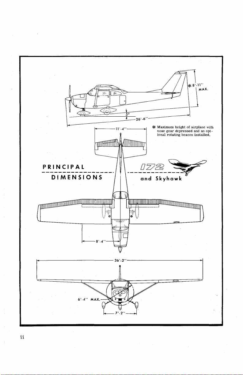
Maximum
nose
ional
gear
rotating
height
of
depressed
beacon
airplane
and an
installed.
with
opt-
PRINCIPAL
DIMENSIONS
,__-------------36'-2"--------------1
ii
___
D z?f!2
and
Skyhawk
~-<7

TABLE
OF
CONTENTS
====================Page=
SECTION
SECTION
SECTION
SECTION
OWNER
SECTION
SECTION
ALPHABETICAL
I -
II -
Ill -OPERATING
IV-
FOLLOW-UP
V -
VI -OPTIONAL
OPERATING
DESCRIPTION
OPERATING
CARE
OPERATIONAL
OF
INDEX
THE
SYSTEM
........................................
CHECK
AND
DETAILS
LIMITATIONS
AIRPLANE
DATA
SYSTEMS
LIST
...........................
..............
......................
............. 3-1
............ 4-1
...................... 5-1
...................... 6-1
1-1
2-1
4-
lndex-1
s
iii
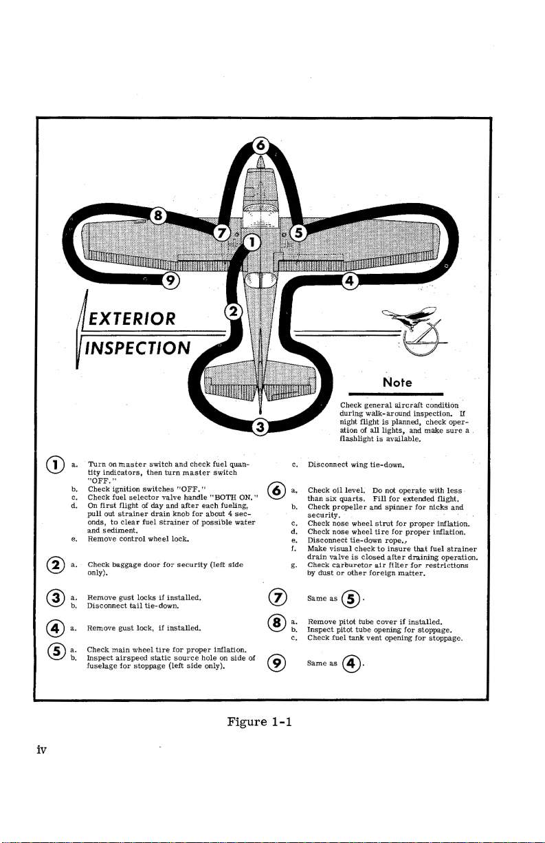
a.
G)
b.
c.
d.
e.
a.
®
a.
@
b.
@a.
®~:
Tu1·n on
tity
indicators,
"'
OFF.
Check
Check
On
first
pull
out
onds,
and
sediment.
Remove
Che
ck
on
ly).
Remove
Dis
conn
Remove
Check
Ins
pect
fuselage
mast
'"
ignition
fuel
selector
flight
strainer
to cle
control
baggage
gust
ect
tail
gust
main
airspeed
for
a r
wheel
stoppage
er switch
and
then
turn
master
switches "OFF."
valve
of
day
and
after
drain
knob
fuel
strainer
wheel
lock.
door
for sec
locks
if
in
stalled.
tie-down
.
lock,
if
installed.
tire
for
static sour
(left
che
handle
for
of
urity
proper
ce
side
ck fuel
switch
"BOTH
each
fueling,
about 4
possible
(le
ft
infl
hole
on
only).
quan-
sec
water
side
ation.
side
ON."
-
of
@
(j)
®
®
c.
a.
b.
c.
d .
e.
!.
g.
a.
b.
c.
DiSconnect
Check
oil leve
than
six
Check
prop
security.
Check
nose
Che
ck
nose
Disconnect
Make
visual checkto
drain
valve
Check
carburetor
by du
st
or
Same
as@·
R
emove
Inspect
pil
Che
ck
fuel
Same
as
Check
during
night
flight
ation of
flashlight
wing
l.
quarts.
ell
er
wheel
whee
tie
- down rope,,.
is
oth
er
pitot
tube
ot
tube
tank
@·
clos
Note
general aircraft
walk-around
is planned,
all
lights,
and
is
available.
tie-down
.
Do not
operate
Fill
for
extended
and
spinner
strut
for
proper
l
ti
re
for
proper
insure
ed
after
draining
air
filt
e r
cover
opening
opening
for
matter.
if
installed.
for
foreign
vent
condition
inspection.
check
make
with l
flight.
for
nicks
inflation.
inflation.
that
fuel
operation.
restrictions
stop
page.
for
stoppag
If
oper-
sure
ess
and
strainer
e.
a
-
iv
Figure
1-1
operating
-----"
•
check
list
it
One of the
and
flying
your
airplane's
by
reviewing
whose
operate
points
you
in
within
I
be
function
Section I lists,
your
true
form
that
need
The
all
respects.
tions
that
the
and
II
are
obtained
flight
BEFORE
(1) Make an
BEFORE
first
enjoyment
equipment,
this
equipment
and
operation
in
airplane
as
it
is
you would
for a typical
need
entire
considerably
and
operational
There
to
be
range
indicated
from
the
ENTERING
exterior
STARTING
steps
in
from
your
Pilot's
efficiently
want
to
flight.
are
mastered.
of
operation.
airspeeds.
Airspeed
THE
inspection
THE
obtaining
Cessna
systems,
while
are
Check
longer,
or
characteristics
no
"unconventional"
Correction
the
and
sitting
not
obvious
List
and
safely.
should
know
All
controls
All
Corresponding
AIRPLANE.
in
ENGINE.
utmost
is
to
familiarize
controls.
in
the
airplane.
are
form,
the
It
is
but
it
does
concerning
of
characteristics
respond
airspeeds
Table
accordance
performance,
covered
your
calibrated
in
yourself
This
can
Those
in
steps
necessary
not a check
cover
briefly
the
airplane
in
the
mentioned
Section
with
figure
service,
with
best
be
items
Section
list
in
all
information
are
or
opera-
normal
in
Sections
airspeed
V.
1-1.
done
II.
to
its
of the
normal
way
may
(1)
Seats
(2)
Brakes --Test
(3)
Master
(4)
Fuel
and
Seat
Switch
Selector
Belts --Adjust
and
set.
--
"ON."
--
"BOTH
ON."
and
lock.
1-1

STARTING
(1)
Carburetor
(2)
Mixture --Rich.
(3)
Primer --As
(4)
Ignition
(5)
Throttle --Open
(6)
Propeller
(7)
Starter --Engage.
THE
ENGINE.
Heat --Cold.
required.
Switch --"BOTH."
1/8".
Area --Clear.
BEFORE
TAKE-OFF.
(1)
Throttle
(2)
Engine
(3)
Magnetos --Check
netos).
(4)
Carburetor
(5)
Flight
(6)
Trim
(7)
Cabin
(8)
Flight
TAKE-OFF.
NORMAL
MAXIMUM
TAKE-OFF.
(1) Wing
(2)
Carburetor
(3)
Power --Full
(4)
Elevator
(5)
Climb
PERFORMANCE TAKE-OFF.
(1)
Wing
(2)
Carburetor
(3)
Brakes --Apply.
(4)
Power --Full
(5)
Brakes --Release.
(6)
Elevator
Setting --1600
Instruments --Within
Heat --Check.
Controls --Check.
Tab --"TAKE-OFF."
Doors --Closed
Instruments
Flaps --0°
Heat --Cold.
throttle
Control --Lift
Speed --85
Flaps --0°
Heat --Cold.
throttle.
Control --Slightly
RPM.
(75
RPM
and
and
Radios --Set.
(applied
nosewheel
MPH.
green
maximum
locked.
smoothly).
tail
low
arc
and
differential
at
60
..
generator
MPH.
light
between
out.
mag-
1-2
(7)
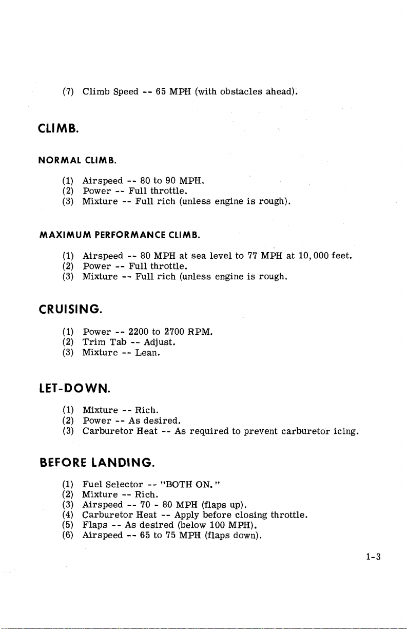
CLIMB.
Climb
Speed --65 MPH (with
obstacles
ahead).
NORMAL
MAXIMUM
CLIMB.
(1)
Airspeed
(2)
Power --Full
(3)
Mixture --Full
PERFORMANCE
(1)
Airspeed
(2)
Power --Full
(3)
Mixture --Full
CRUISING.
(1)
Power
(2)
Trim
(3)
Mixture --Lean.
LET-DOWN.
(1)
Mixture --Rich.
(2)
Power --As
(3)
Carburetor
--
80
to
90 MPH.
throttle.
rich
CLIMB.
--
80 MPH
throttle.
rich
--
2200 to 2700
Tab --Adjust.
desired.
Heat --As
(unless
at
sea
(unless
RPM.
required
engine
level
engine
is
to
to
prevent
rough).
77
MPH
is
rough.
at
10,000
carburetor
feet.
icing.
BEFORE
(1)
(2)
(3)
(4)
(5)
(6)
LANDING.
Fuel
Selector --"BOTH
Mixture --Rich.
Airspeed
Carburetor
Flaps --As
Airspeed --65 to 75 MPH
--
70 - 80 MPH (flaps up).
Heat --Apply
desired
(below 100 MPH).
ON."
before
(flaps
closing
down).
throttle.
1-3
NORMAL
LANDING.
(1) Touchdown --Main
(2)
Landing
(3)
Braking --Minimum
AFTER
SECURE
LANDING.
(1)
Flaps --Up.
(2)
Carburetor _Heat --Cold.
Al
RC
(1)
Mixture --Full
(2) All
(3)
(4)
Switches
Brakes --Set.
Control
wheels
Roll --Lower
RAFT.
lean.
- -
"OFF."
Lock
-'-
Installed.
first.
nosewheel
required.
gently.
1-4

-~-8!'-C-tion
2_-_lt,
9s:
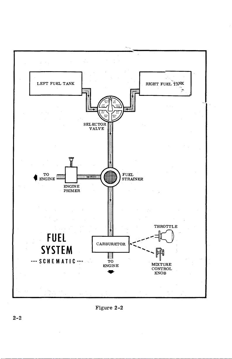
The
following
function
section
in
quiring
FUEL
wing.
also
Check
further
SYSTEM.
Fuel
From
and
List
is
and a strainer
Refer
information
FUEL
I
TANKS NO.
paragraphs
operation
covers
form
explanation
supplied
these
to
the
to
figure
refer
to
QUANTITY
is
not
in
somewhat
in
Section
will
to the engine
tanks,
fuel
carburetor.
2-1
for
fuel
Lubrication
USABLE
FUEL
ALL
FLIGHT
CONDITIONS
operating
describe
obvious when
I. Only
be
flows
quantity
greater
those
found
from
by
and
Servicing
the
systems
sitting
detail
items
here.
two
aluminum
gravity
data.
and
in
the
some
of
of the
tanks,
through a
For
fuel
Procedures
DATA (U.S. GALLONS)
ADDITIONAL
USABLE
(LEVEL
FLIGHT)
FUEL FUEL
UN.USABLE
(LEV,EL
'
details
equipment
airplane.
the
items
Check
system
FLIGHT)
one
selector
in
Section
List
whose
This
listed
re-
in
each
valve
servicing
4.
TOTAL
FUEL
VOLUME
EACH
LEFT
WING
·
RIGHT
WING 1 19. 5
1. 0
1. 0
2-1.
gal.
gal.
0. 5
0. 5
gal.
gal.
1
19.5gal.
gal.
Figure
21. 0 gal.
21. 0 gal.
2-1
LEFT
FUEL
TANK
FUEL
SYSTEM
····SCHEMATIC···•
SELECTOR
VALVE
CARBURETOR
L---.....
,"j
!ii
Iii
l
. ,----'
TO
ENGINE
•
FUEL
STRAINEE
THROTTLE
__
.,,,,...,,,,...,,,..
,--
....................
--lh--1'1
.~
.
~
.
MIXTURE
CONTROL
KNOB
.
2-2
Figure
2-2
FUEL
STRAINER
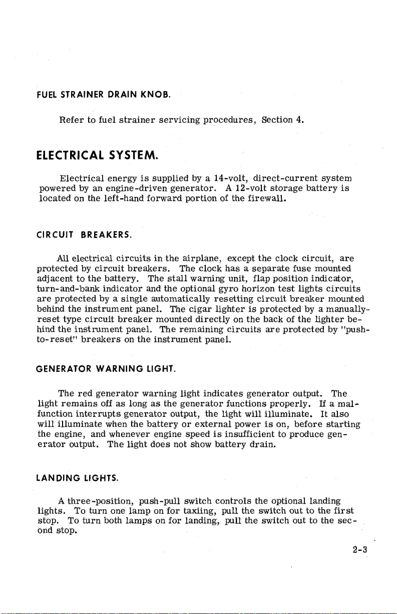
Refer
to fuel
DRAIN KNOB.
strainer
servicing
procedures,
Section 4.
ELECTRICAL
Electrical
powered
located
CIRCUIT BREAKERS.
protected
adjacent
turn-and-bank
are
behind
reset
hind
to-reset11
GENERATOR
light
function
will
the engine, and
erator
on the
All
electrical
to
protected
the
type
the
instrument
The
red
remains
interrupts
illuminate
output.
SYSTEM.
energy
by
an
engine-driven
left-hand
by
circuit
the
battery.
indicator
by a
instrument
circuit
breakers
WARNING
generator
off
when the
whenever
The
circuits
single
breaker
as
is
supplied
forward
in
breakers.
The
and
automatically
panel.
mounted
panel.
on
The
the
instrument
LIGHT.
warning
long
as
generator
battery
engine
light
does
by a
14-volt,
generator. A 12-volt
the
stall
the
portion
airplane,
The
optional
clock
warning
gyro
of the
firewall.
except
has a separate
unit, flap
horizon
resetting
The
cigar
lighter
directly
remaining
is
on
the
circuits
panel.
light
the
generator
output, the
or
external
speed
not show
indicates
is
battery
generator
functions
light
will
power
insufficient
direct-current
storage
the
clock
fuse
position
test
lights
circuit
breaker
protected
back
of
the
are
protected
output. The
properly.
illuminate.
is
on,
before
to
produce
drain.
system
battery
circuit,
mounted
indicator,
circuits
mounted
by a
manually-
lighter
by 11push-
If a
It
starting
gen-
is
are
be-
mal-
also
LAN
DING
lights.
stop.
ond
stop.
LIGHTS.
A
three-position,
To
turn
To
turn
both
one
push-pull
lamp
lamps
on
on
switch
for
taxiing, pull the switch
for
controls
landing, pull the
the optional landing
out
to the
switch
out to the
first
sec-
2-3
CABIN
air
1/2"
pulling
HT"
no
HEATING
For
cabin
temperature,
for a small
the knob
knob
pulled
heat
is
desired
AND
ventilation,
pull
the "CABIN
amount
out
farther;
full
out
in
the
STARTING ENGINE.
VENTILATION
pull
the "CABIN AIR" knob out.
HT"
knob
of
cabin
heat.
Additional
maximum
and
the "CABIN AIR" knob
cabin,
the
heat
"CABIN
SYSTEM.
out
approximately
heat
is
available
pushed
HT"
knob
To
raise
1/4"
is
available
with the "CABIN
full
in.
When
is
pushed
full
the
to
by
in.
Ordinarily
primer
throttle
it
the
cleaned
the
engine
procedure
engine)
As
it
30
weather,
serious
heat
in
open
may
be
Weak
exhaust
from
mixture
through
If
the engine
it
soon
as
running.
After
seconds
engine
unless
necessary
will
stop
TAXIING.
When
a
minimum
2-3
to
maintain
the
engine
warm
temperatures
approximately
intermittent
stack
indicates
the
combustion
control
without
the
starting,
in
icing
taxiing,
and
full
several
any
is
underprimed
not
fire
cylinders
the
summertime
engine and
damage.
conditions
it
that
all
directional
starts
to
continue
explosions
lean
revolutions
additional
at
all,
begin
if
the
oil
investigate.
After
is
important
controls
easily
to
six
strokes
1/8
inch.
priming
followed by
overpriming
chambers
and
the
throttle
with the
priming.
(most
and
additional
to
fire,
gage
does
and
about
starting,
prevail.
that
be
control
utilized
and
with
bne
or
two
in
cold
In
extremely
while
cranking.
puffs
of
or
flooding.
by the following
full
open;
starter.
likely
in
cold
priming
open
the
throttle
not
begin
to show
twice
that
long
Lack
of
oil
and
pressure
use
use
taxiing
avoid the
speed
(see
balance.
strokes
weather,
cold
temperatures,
black
Excess
procedure:
then
Repeat
weather
will
be
slightly
pressure
in
very
of
carburetor
of
brakes
diagram,
of the
with
the
smoke
crank
necessary.
can
fuel
the
with a
be
from
can
the
starting
to
keep
within
cold
cause
held
figure
be
Set
cold
to
speed
2-4
Taxiing
to
avoid
over
abrasion
loose
gravel
and
stone
or
cinders
damage
should
to
the
be
done
propeller
at
low engine
tips.
Full
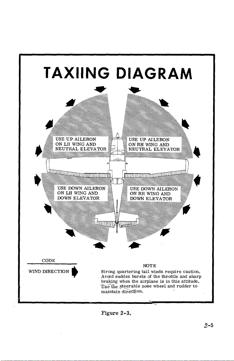
TAXIING
~··
DIAGRAM
•
WIND
CODE
DIRECTION
t
Strong
Avoid
braking
·
use-ffie
maintain
Figure
quartering
sudden
when
5t'::erable
di~-i:),;;jJon.
2-3.
bursts
the
airplane
NOTE
tail
of
nose
winds
the
wheel
require
throttle
is
in
and
this
rudder
caution.
and
sharp
attitude.
to
2-5

throttle
tips.
portant
start
back
of
dents
rected
run-ups
When
that
rolling
..
the
appear
as
described
over
take-offs
the
throttle
before
propeller
in
the
loose
gravel
must
be
be
advanced
high
RPM
rather
propeller
in
than
Section 4 under
are
made
is
developed,
pulled
blades,
especially
over a gravel
slowly.
they
This
and
into
it.
should
propeller
harmful
surface,
allows
the
gravel
When
unavoidable
be
immediately
care.
to
propeller
it
is
the
airplane
will
very
im-
to
be blown
small
cor-
BEFORE
WARM
ing,
engine
MAGNETO
the
switch
move
tween
75
HIGH
RPM
ficiency
run
buretor
UP.
Since
precautions
operation
The
magneto
ignition
back
the
the two
RPM.
RPM
If
there
checks
exists.
smoothly
heat
TAKE-OFF.
the
engine
CHECK.
switch
to
switch
MAGNETO
is
at
and
off.
is
should
on
the
check
first
"BOTH"
to the
magnetos
a doubt
higher
If
a
turn
closely
be
ground.
should
to
position
"L"
operated
concerning
engine
full
approximately
cowled
taken
be
"R"
position,
position
CHECKS.
speeds
throjjle
for
to
avoid
overheating
made
at
and
to
clear
the
and
note
individually
the
operation
will
run-up
is
2230 to 2330
efficient
1600
note
other
RPM.
should
usually
necessary
in-flight
RPM
RPM.
set
The
of the
confirm
RPM
during
as
follows:
Next
of
plugs.
difference
not
be
ignition
whether a de-
the
engine
with
engine
prolonged
Move
move
Then
more
than
system,
should
the
car-
cool-
the
be-
An
one
side
magneto
ting
specified.
2-6
absence
of the
timing
of
RPM
ignition
has
]!~eh
drop
Ffiay
Y
sy..gfem
or
"bumped-up"
be
an
should
and
indication
be
caul?~
is
set
of fa:uity
for
suspicion
in
advance
grounding
that
of the
set-
of-
the
TAKE-OFF.
POWER.
Since the
it
is
important
run.
is
good
justified
take-off
Prior
should be
WING
Normal
flaps
up. The
10%,
but
fore
the
off
from
If 10 ° of
extended
ception
where
Flap
take-off.
CHECK.
use
to
Any
signs
of
cause
for
in
making a thorough
is
attempted.
to
take-off
leaned
FLAP
to give
SETTINGS.
and
obstacle
use
this
advantage
use
of 10° flap
soft
or
rough
flaps
rather
to
climb
this
than
rule
would
deflections
of
full
throttle
check
full-throttle
rough
engine
discontinuing
from
fields
maximum
clearance
of
10°
flaps
is
lost
is
reserved
fields
with
are
used
in
retract
would
be
of 30°
them
be
in
marginal
to
is
not
recommended
engine
operation
the
take-off.
full-throttle,
above 5000
RPM
in a full-throttle,
take-offs
will
shorten
in
the
climb
for
minimum
no
obstacles
ground
40°
in
a high
with
are
runs,
the
altitude
flaps
not
operation
or
sluggish
If
this
static
run-up
ft.
elevation,
are
performed
the
ground
to a 50-foot
ground
ahead.
it
is
preferable
climb
to
the
take-off
10°
(1st
notch).
recommended
in
the
early
engine
occurs,
before
the
static
run
approximately
obstacle.
runs
obstacle.
in
hot
at
any
static
run-up,
in
the
take-off
acceleration
you
are
another
mixture
run-up.
with wing
There-
or
for
take-
to
leave
The
weather
time
for
them
ex-
PERFORMANCE CHARTS.
Consult
various
CROSSWIND
Take-offs
minimum
drift
angle
the
gross
weight,
TAKE-OFFS.
into
flap
setting
immediately
take-off
altitude,
strong
necessary
after
chart
in
and headwind
crosswinds
for
take-off.
Section
normally
the
5,
field
The
for
take-off
conditions.
are
length,
airplane
distances
performed
to
minimize
is
accelerated
under
with the
the
to
2-7
 Loading...