

Cessna SKYHAWK 172M 1976 Pilot Operating Handbook

PILOT'S
OPERATING
HANDBOOK
~
Cessna®
1976
Skyhawk
CESSNA
MODEL
172M
j

PERFORMANCE
-
SPECIFICATIONS
CESSNA
MODEL
172M
PERFORMANCE
-SPECIFICATIONS
SPEED:
Maximum
at
Sea
Level
. . . . . . . . . . . . . . .
125
KNOTS
Cruise,
75%
Power
at
8000
Ft
. . . . . . . . . . . .
120
KNOTS
CRUISE:
Recommended
Lean
Mixture
with
fuel
allowance
for
engine
start,
taxi,
takeoff,
climb
and
45
minutes
reserve
at
45%
power.
75%
Power
at
8000
Ft
. . .
38
Gallons
Usable
Fuel
75%
Power
at
8000
Ft
. . .
48
Gallons
Usable
Fuel
Maximum
Range
at
10,000
Ft
38
Gallons
Usable
Fuel
Maximum
Range
at
10,000
Ft
48
Gallons
Usable
Fuel
RATE
OF
CI.JMB AT
SEA
LEVEL
SERVICE CEILING . . . . . . .
TAKEOFF
PERFORMANCE:
Ground
Roll
. . . . . . . . . .
Total
Distance
Over 50-Ft
Obstacle
LANDING
PERFORMANCE:
Ground
Roll
. . . . . . . . . . .
Total
Distance
Over
50-Ft
Obstacle
STALL
SPEED
(CAS):
Flaps
Up,
Power
Off . .
Flaps
Down,
Power
Off .
MAXIMUM WEIGHT
....
STANDARD
EMPTY
WEIGHT:
Skyhawk
.....
. .
Skyhawk II
...
. . .
MAXIMUM USEFUL LOAD:
Skyhawk
.....
. .
Skyhawk II
.....
.
BAGGAGE ALLOWANCE
..
.
WING LOADING:
Pounds/Sq
Ft
POWER LOADING:
Pounds/HP
FUEL
CAPACITY:
Total
Standard
Tanks
Long Range
Tanks
.
OIL
CAPACITY
ENGINE: Avco
L;c~~in~
:
150
BHP
at
2700
RPM
PROPELLER:
Fixed
Pitch,
Diameter
0 1
057
13
I
~ANO
8000
7/76
Range
Time
Range
Time
Range
Time
Range
Time
450
NM
3. 9 HRS
595 NM
5.1
HRS
480
NM
4. 8 HRS
640 NM
6. 3
HRS
645
FPM
13,
100
FT
865FT
1525
FT
520FT
1250
FT
50
KNOTS
44
KNOTS
2300
LBS
1387
LBS
1412
LBS
913
LBS
888
LBS
120
LBS
13.2
15.3
42 GAL.
52
GAL.
8
QTS
0-320-E2D
75 IN.
) I . ,
()I
~
I I
1976
00
El
72
S o ' o
• 0
C S
'A
AI C
V/
10
I A
PA
SA
CONGRATULATIONS
CONGRATULATION
S
..
CESSNA
MODEL
172M
. .
h
been
designed and
construct
ed
to
We
lcome
to
the ranks
of
Cessna
owners! Your
Cessnaf
as
It
·s
our
desire
that
you
will
find
give
you the most in performance, economy,
and
com ort. f
~I
experience.
flying it, either
for
business
or
pleasure,
a pl
easant
and pro Ita e
.
1
et the most pleasure and
utili
ty
This handbook
has
been
prepared
as
a guide
to
he
P you g , ui
pment
operating pro -
from your
airplan
e.
It
contains
inf
ormation about
your
Cessna
seq
W '
to read
· f
·t
ervicing and care e urge
you
cedures,
and
performance;
and
suggestions
or I s s ·
it
from cover
to
cover,
and
to refer to it frequently.
d
·th purchase
of a Cessna.
World
-
Our
int
erest in your flying pl
easure
has
not
cease
WI
your
wide, the
Cessna
Dealer Organization backed by the
Cessna
Service
Department stands ready
to
serve
you. The following
services
are
offered by most
Cessna
Dealers:
THE
CESSNA
WARRANTY-- It
is
designed
to
provide you
with
the
most
compre-
hensi
ve
coverage
possible:
a.
No
exclusions
b.
Coverage
includes parts
and
labor
c.
Available
at
Cessna Dealers
wor
ld wide
d.
Best
in the industry
Spec
ific benefi
ts
and
provisions
of
the warranty plus other
important
benefits
for
you
are
contained in
your
Customer
Care
Program book suppli
ed
with
your
airplane.
Warranty service
is
availab
le
to
you at any authorized
Cessna
Dealer
throughout
the
world upon presentation
of
your
Customer
Care
Card which establishes your
eli
gibil-
it
y under the warranty.
FACTORY
TRAINED
PERSONNEL
to
provide you
with
courteous
expert
service.
FACTORY A
PPR
OVED SERVI
CE
EQUIPMENT
to
provide you
with
the
most
efficient and accurate workmanship
poss
ibl
e.
A STOCK OF GENUI
NE
CESSNA SERVICE PARTS on hand when
you
need
them.
THE LATEST
AUT
HORITATIV
E IN
FORMATION
FOR
SERVICING
CESSNA
A
IRPL
ANES, since
Cessna
Dealers
have
all
of
the Service Manuals and Parts
Catalogs,
kept
current
by
Service Letters and Servi
ce
News Letters, published
by
Cessna Air
craft
Company.
We
urge all
Cessna
owners
to
use
the
Cessna
Dealer Organization
to
the full est.
A current
Cessna
Dealer
Directory
accompanies
your
new air
plane
The
D. t · ·
f ·
1rec
ory
IS
rev1sed
requently, and a
current
copy
can
be
obtained
from your
Cessna
Dealer.
Make our
D1rectory one
of
your
cross-country flight planning aids· a
warm
welco
· y
every
Cessna Dealer. ' me awa1
ts
you
at
ii
CESSNA
MODEL
172M
TABLE
OF
CONTENTS
TABLE
OF
CONTENTS
GENERAL
..
LIMITATIONS
EMERGENCY
PROCEDURES
NORMAL
PROCEDURES
SECTION
1
2
3
4
PERFORMANCE
. . . . 5
WEIGHT
& BALANCE/
EQUIPMENT
LIST
. . . . . . . . . . • • . . 6
AIRPLANE & SYSTEMS
DESCRIPTIONS
. . . . . . . . . . • • . . 7
AIRPLANE
HANDLING,
SERVICE & MAINTENANCE
. . • . . . • . • 8
SUPPLEMENTS
(Optional
Systems
Description
& Operating Procedures) • . . . . • . • . . 9
This
handbook
will
be
kept
current
by
Service Letters published
by
Cessna
Aircraft
Company. These
are
distributed
to
Cessna Dealers
and
to
those
who
subscribe
through
the
Owner
Follow-Up System. If
you
are
not
receiving subscription service,
you
will
want
to
keep
in
touch
with
your
Cessna Dealer
for
information
concerning
the
change
status
of
the
handbook.
Subsequent
changes will be made in
the
form
of
stickers. These
should
be
examined and attached
to
the
appropria
te
page in
the
handbook
immediately after receipt;
the
handbook
should
not
be used
for
opera-
tional purposes until
it
has been
updated
to a current
status.
iii/(iv
blank)
CESSNA
MODEL 172M
SECTION
1
GENERAL
TABLE OF
CONTENTS
Three
View
...
Introduction . . .
Descriptive
Data
.
Engine .
Propeller
..
Fuel
....
Oil
. I
•••
Maximum
Certificated
Weights
Standard
Airplane
Weights
Cabin and
Entry
Dimensions
. .
Baggage
Space
and
Entry
Dimensions
.
Specific
Loadings.
. . . . . . . . .
Symbols,
Abbreviations
and
Terminology
.
General
Airspeed
Terminology
and
Symbols .
Meteorological
Terminology
. . . . . . . .
Engine
Power
Terminology
. . . . . . . .
Airplane
Performance
and
Flight
Planning
Terminology
Weight and
Balance
Terminology
. . . . . . . . . . .
SECTION 1
GENERAL
Page
1-2
1-3
1-3
1-3
1-3
1-3
1-4
1-5
1-5
1-5
1-5
1-5
1-6
1-6
1-6
1-7
1-7
1-7
1-1
SECTION 1
GENERAL
1-2
PIVOT POINT
36'
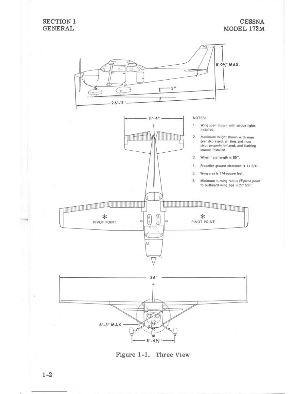
Figure
1-1.
Three
View
NOTES:
CESSNA
MODEL 172M
1.
Wing
span shown with
strobe
lights
installed.
2.
Maxim
um
heig
ht
shown
with
nose
gear depressed,
all
tires and nose
strut
properly inflated, and flashing
beacon installed.
3. Wheel ' .ase length
is
65".
4. Propeller ground clearance
is
11
3/4".
5. Wing area
is
174 square feet.
6. Minimum turning radius
(*pivot
poi
nt
to outboard wing tip)
is
27' 5%".
*
PIVOT POINT
CESSNA
MODEL
172M
SECTION 1
GENERAL
INTRODUCTION
This
handbook
contains 9 sections,
and
includes
the
material
required
to
be
furnished
to
the
pilot
by
CAR
Part
3.
It
also
contains
supplemental
data
supplied
by
Cessna
Aircraft
Company.
Section 1
provides
basic
data
and
information
of
general
interest.
It
also
contains
definitions
or
explanations
of
symbols,
abbreviations,
and
terminology
commonly
used.
DESCRIPTIVE
DATA
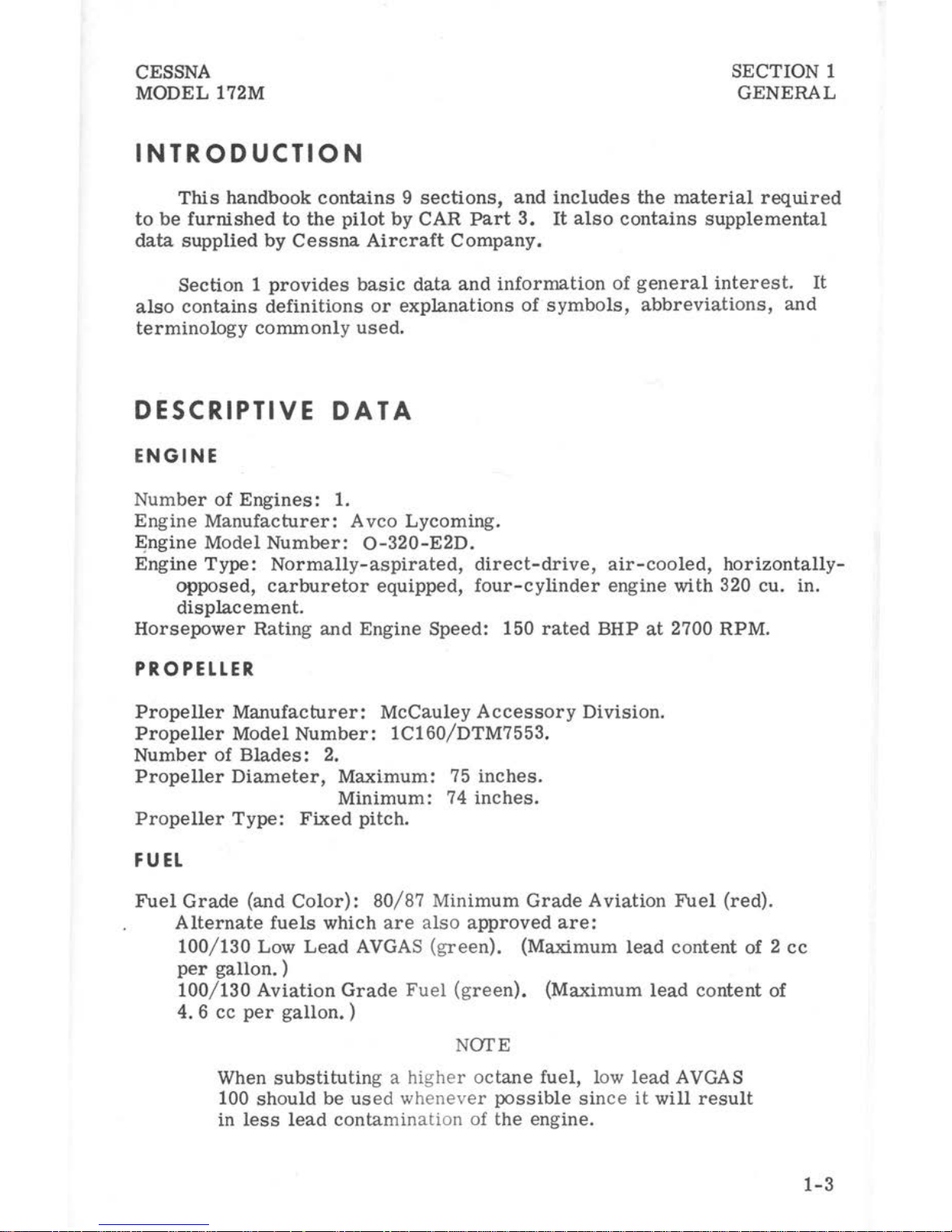
ENGINE
Number
of
Engines:
1.
Engine
Manufacturer:
Avco
Lycoming.
E;ngine Model
Number:
0-320-E2D.
Engine
Type:
Normally-aspirated,
direct-drive,
air-cooled,
horizontally-
opposed,
carburetor
equipped,
four-cylinder
engine
with
320 cu. in.
displacement.
Horsepower
Rating
and
Engine Speed: 150
rated
BHP
at
2700 RPM.
PROPELLER
Propeller
Manufacturer:
McCauley
Accessory
Division.
Propeller
Model
Number:
1C160/DTM7553.
Number
of
Blades:
2.
Propeller
Diameter,
Maximum:
75
inches.
Minimum:
74
inches.
Propeller
Type:
Fixed
pitch.
FUEL
Fuel
Grade
(and
Color):
80/87
Minimum
Grade
Aviation
Fuel
(red).
Alternate
fuels
which
are
also
approved
are:
100/130
Low
Lead
AVGAS
{green). {Maximum
lead
content
of 2
cc
per
gallon. )
100/130
Aviation
Grade
Fuel
{green).
(Maximum
lead
content
of
4. 6
cc
per
gallon.
)
NarE
When
substituting
a higher
octane
fuel, low
lead
AVGAS
100
should
be
used whenever possible
since
it
will
result
in
less
lead
contamin
ation
of the engine.
1-3

SECTION 1
GENERAL
CESSNA
MODEL
172M
Fuel
Capacity:
Oil
Standard
Tanks:
Total
Capacity:
42
gallons.
Total
Capacity
Each
Tank:
21
gallons.
Total
Usable:
38
gallons
.
Long Range
Tanks:
Total
Capacity:
52
gallons.
Total
Capacity
Each
Tank:
26
gallons.
Total
Usable:
48
gallons.
NOfE
To
ensure
maximum
fuel
capacity
when
refueling, place
the
fuel
selector
valve
in
either
LEFT
or
RIGHT
posi-
tion to
prevent
cross-feeding.
Oil
Grade
(Specification):
MIL-L-6082
Aviation
Grade
Straight
Mineral
Oil:
Use to
replenish
supply
during
first
25
hours
and
at
the
first
25-hour
oil
change.
Continue
to
use
until a total
of
50
hours
has
accumulated
or
oil
consumption
has
stabilized
.
NOTE
The
airplane
was
delivered
from
the
factory
with a
corro-
sion
preventive
aircraft
engine
oil.
This
oil
should
be
drained
after
the
first
25
hours
of
operation.
MIL-L-22851
Ashless
Dispersant
Oil:
This
oil
must
be
used
after
first
50
hours
or
oil
consumption
has
stabilized.
Recommended
Viscosity
For
Temperature
Range:
SAE
50
above
l6°C
(60°F).
SAE 10W30
or
SAE 30
between
-18°C
(0°F)
and
21°C (70°F).
SAE 10W30
or
SAE
20
below
-12°C(l0°F}.
NOfE
I
Multi-viscosity
oil
with a
range
of SAE 10W30
is
recom-
mended
for
improved
starting
in
cold
weather.
Oil
Capacity:
1-4
Sump: 8
Quarts
.
Total: 9 Quarts.
CESSNA
MODEL 172M
SECTION 1
GENERAL
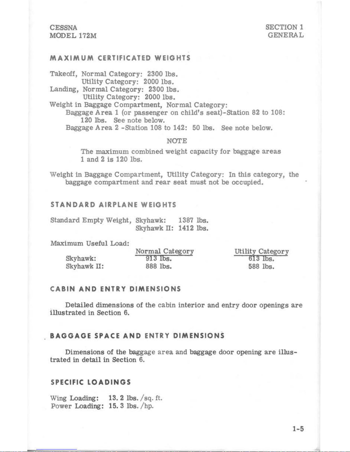
MAXIMUM
CERTIFICATED
WEIGHTS
Takeoff,
Normal
Category:
2300
lbs.
utility
Category:
2000
lbs.
Landing, Nor m
al
Category:
2300
lbs.
Utility
Category:
2000
lbs.
Weight
in
Baggage
Compartment,
Normal
Category:
Baggage
Area 1 (or
passenger
on
child's
seat)-Station
82 to 108:
120
lbs.
See note below.
Baggage
Area 2 -Station
108 to 142:
50
lbs. See note below.
NOTE
The
maximum
combined
weight
capacity
for
baggage
areas
1
and 2 is
120 lbs.
Weight
in
Baggage
Compartment,
Utility
Category:
In
this
category,
the
baggage
compartment
and
rear
seat
must
not
be
occupied.
STANDARD AIRPLANE WEIGHTS
Standard
Empty Weight, Skyhawk: 1387 lb
s.
M
aximum Usefu
l L
oad
:
Sky hawk:
Skyhawk
II:
Skyhawk II: 1412 lbs.
Normal Category
913
lbs.
888 l
bs.
CA
BIN
AND
ENTRY
DIME
NSIONS
Utility Categor y
613
lbs.
588 lbs.
Detailed
dimensions
of the
cabin interior
and
entry
door
openings
are
illustrated
in
Section 6.
BAGGAGE SPACE
AND
ENTRY
DIMENSIONS
Dimensions
of
the
baggage a
rea
and
baggage
door
opening
are
illus-
trated
in
detail
in
Section 6.
SPECIFIC
LOADINGS
Wing Loading: 13. 2 lbs. / sq.
ft.
Po
wer Loading: 15. 3 lbs. / hp.
1-5
---....
SECTION 1
GENERAL
CESSNA
MODEL
172M
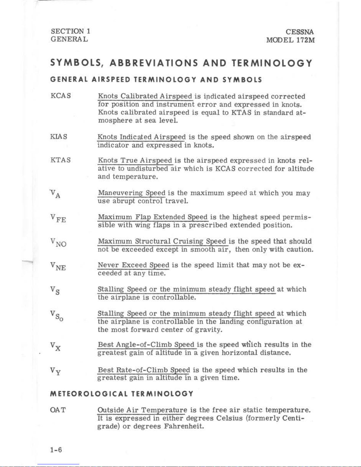
SYMBOLS,
ABBREVIATIONS
AND
TERMINOLOGY
GENERAL
AIRSPEED
TERMINOLOGY
AND
SYMBOLS
KCAS
KIAS
KTAS
'VA
VFE
VNO
VNE
Vs
Vs
0
vx
Vy
Knots
Calibrated A irs
peed
is
i!1dicated
airspeed
corrected
for
position
and
instrument
error
and
expressed
in
knots.
Knots
calibrated
airspeed
is
equal
to KTAS
in
standard
at-
mosphere
at
sea
level.
Knots
Indicated
Airspeed
is
the
speed
shown on
the
airspeed
indicator
and
expressed
in
knots.
Knots
True
Airspeed
is
the
airspeed
expressed
in
knots
rel-
ative
to
undisturbed
air
which
is
KCAS
corrected
for
altitude
and
temperature.
Maneuvering
Speed
is
the
maximum
speed
at
which you
may
use
abrupt
control
travel.
Maximum
Flap
Extended
Speed
is
the
highest
speed
permis-
sible
with
wing
flaps
in a prescribed
extended
position.
Maximum
Structural
Cruising
Speed
is
the
speed
that
should
not
be
exceeded
except
in
smooth
air,
then
only
with
caution.
Never
Exceed
Speed
is
the
speed
limit
that
may
not
be
ex-
ceeded
at
any
time.
Stalling
Speed
or
the
minimum
steady
flight
speed
at
which
the
airplane
is
controllable.
Stalling
Speed
or
the
minimum
steady
flight
speed
at
which
the
airplane
is
controllable
in
the
landing
configuration
at
the
most
forward
center
of
gravity.
Best
Angle-of-Climb
Speed
is
the
speed
wnich
results
in
the
g
reatest
gain
of
altitude
in a given
horizontal
distance.
Best
Rate-of-Climb
Speed
is
the
speed
which
results
in
the
greatest
gain
in
altitude
in a given
time.
METEOROLOGICAL
TERMINOLOGY
OAT
Outside
Air
Temperature
is
the
free
air
static
temperature.
1-6
It
is
expressed
in
either
degrees
Celsius
(formerly
Centi-
grade)
or
degrees
Fahrenheit.
CESSNA
MODEL
172M
SECTION 1
GENERAL
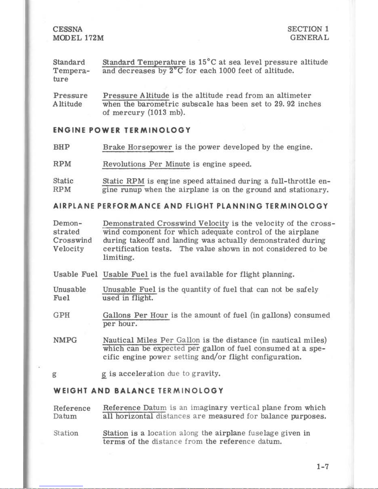
Standard
Temperature
Pressure
Altitude
Standard
Temperature
is
l5°C
at
sea
level
pressure
altitude
and
decreases
by 2 C
for
each
1000
feet
of
altitude.
Pressure
Altitude
is
the
altitude
read
from
an
altimeter
when the
barometric
subscale
has
been
set
to 29.
92
inches
of
mercury
(1013 mb).
ENGINE
POWER
TERMINOLOGY
BHP
RPM
Static
RPM
Brake
Horsepower
is
the
power
developed
by the
engine.
Revolutions
Per
Minute
is
engine
speed.
Static
RPM
is
engine
speed
attained
during a full-throttle
en-
gine
runup
when the
airplane
is
on the
ground
and
stationary.
AIRPLANE
PERFORMANCE
AND
FLIGHT
PLANNING
TERMINOLOGY
Demonstrated
Crosswind
Velocity
Demonstrated
Crosswind
Velocity
is
the
velocity
of the
cross-
·wind
component
for
which
adequate
control
of the
airplane
during
takeoff and landing
was
actually
demonstrated
during
certification
tests
.
The
value
shown in not
considered
to
be
limiting.
Usable
Fuel
Usable
Fuel
is
the
fuel
available
for
flight
planning.
Unusable
Fuel
GPH
NMPG
g
Unusable
Fuel
is
the
quantity
of
fuel
that
can not be
safely
used
in flight.
Gallons
Per
Hour
is
the
amount
of
fuel
(in
gallons)
consumed
per
hour.
Nautical
Miles
Per
Gallon
is
the
distance
(in
nautical
miles)
which
can
be
expected
per
gallon
of
fuel
consumed
at a spe-
cific
engine
power
setting
and/or
flight
configuration.
~is
acceleration
due to
gravity.
WEIGHT
AND
BALANCE
TERMINOLOGY
Reference
Reference
Datum
is
an
imaginary
vertical
plane
from
which
Datum
all
horizontal
dist
ances
are
measured
for
balance
purposes.
Statio
n
Station
is a locati
on along the
airplane
fuselage
given
in
terms
of
the
dist
ance
from
the
reference
datum.
1-7
SECTION
1
GENERAL
Arm
Moment
Center
of
Gravity
(C
. G
.)
e.G.
Arm
e.G.
Limits
Standard
Empty
Weight
CESSNA
MODEL
172M
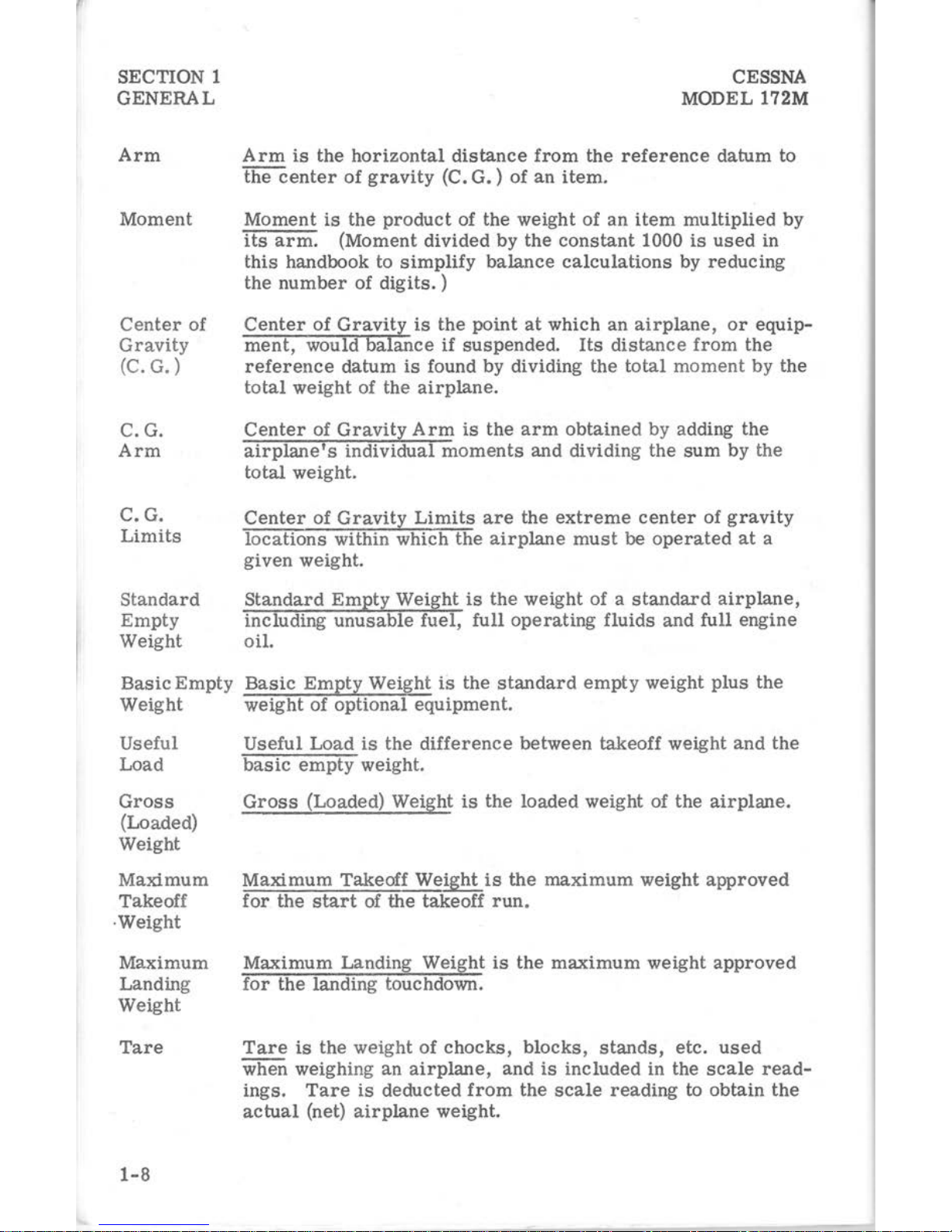
Arm
is
the
horizontal
distance
from
the
reference
datum
to
the
center
of
gravity
(C.
G.)
of
an
item.
Moment
is
the
product
of
the
weight
of
an
item
multiplied
by
its
arm.
(Moment
divided
by
the
constant
1000
is
used
in
this
handbook
to
simplify
balance
calculations
by
reducing
the
number
of
digits.
)
Center
of
Gravity
is
the
point
at
which
an
airplane,
or
equip-
ment,
would
balance
if
suspended.
Its
distance
from
the
reference
datum
is
found
by
dividing
the
total
moment
by
the
total
weight
of
the
airplane
.
Center
of
Gravity
Arm
is
the
arm
obtained
by
adding
the
airplane's
individual
moments
and
dividing
the
sum
by
the
total
weight.
Center
of
Gravity
Limits
are
the
extreme
center
of
gravity
locations
within
which
the
airplane
must
be
operated
at
a
given
weight.
Standard
Empty
Weight
is
the
weight
of a standard
airplane,
including
unusable
fuel,
full
operating
fluids
and
full
engine
oil.
Basic
Empty
Basic
Empty
Weight
is
the
standard
empty
weight
plus
the
Weight
weight
of
optional
equipment.
Useful
Load
Gross
(Loaded)
Weight
Maximum
Takeoff
·Weight
Maximum
Landing
Weight
Tare
1-8
Useful
Load
is
the
difference
between
takeoff
weight
and
the
basic
empty
weight.
Gross
(Loaded) Weight
is
the
loaded
weight
of
the
airplane.
Maximum
Takeoff
Weight
is
the
maximum
weight
approved
for
the
start
of
the
takeoff
run
.
Maximum
Landing
Weight
is
the
maximum
weight
approved
for
the
landing
touchdown.
Tare
is
the
weight
of
chocks,
blocks, stands,
etc.
used
when
weighing
an
airplane,
and
is
included
in
the
scale
read-
ings.
Tare
is
deducted
from
the
scale
reading
to
obtain
the
actual
(net)
airplane
weight.

CESSNA
MODEL
172M
SECTION
2
LIMITATIONS
TABLE OF
CONTENTS
Introduction
. . . . . . . .
Airspeed
Limitations
. . . .
Airspeed
Indicator
Markings
Power
Plant
Limitations
Power
Plant
Instrument
Markings
Weight
Limits
. . . . .
Normal
Category
. .
Utility
Category
. .
Center
of
Gravity
Limits
Normal
Category
.
Utility
Category
.
Maneuver
Limits
Normal
Category
.
Utility
Category
.
Flight
Load
Factor
Limits
Normal
Category
Utility
Category
. . .
Kinds of
Operation
Limits
.
Fuel
Limitations
Placards
.......
.
SECTION 2
LIMITATIONS
Page
2-3
2-4
2-5
2-5
2-6
2-6
2-6
2-7
2-'7
2-7
2-7
2-7
2-7
2-7
2-8
2-8
2-8
2-9
2-9
2-10
2-1/
(2-2 blank)
CESSNA
MODEL
172M
SECTION 2
LIMITATIONS
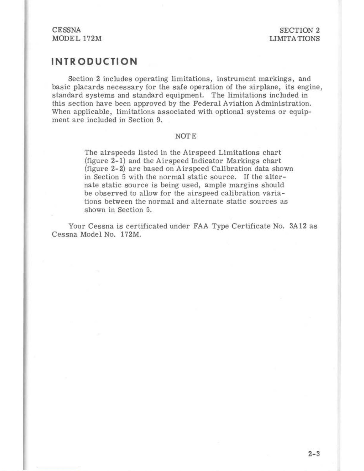
INTRODUCTION
Section 2
includes
operating
limitations,
instrument
markings,
and
basic
placards
necessary
for
the
safe
operation
of the
airplane,
its
engine ,
standard
systems
and
standard
equipment.
The
limitations
included
in
this
section
have
been
approved
by the
Federal
Aviation
Administration.
When
applicable,
limitations
associated
with
optional
systems
or
equip-
ment
are
included
in Section
9.
NOTE
The
airspeeds
listed
in the
Airspeed
Limitations
chart
(figure
2-1)
and
the Ai
rspeed
Indicator
Markings
chart
(figure
2-2)
are
based
on
Airspeed
Calibration
data
shown
in
Section
5 with the
normal
static
source.
If
the
alter-
nate
static
source
is
being
used, ample
margins
should
be
observed
to allow
for
the
airspeed
calibration
varia-
tions
between
the
normal
and
alternate
static
sources
as
shown in
Section
5.
Your
Cessna
is
certificated
under
FAA
Type
Certificate
No. 3A12
as
Cessna
Model No. 172M.
2-3
SECTION 2
LIMITATIONS
AIRSPEED
LIMITATIONS
CESSNA
MODEL
172M
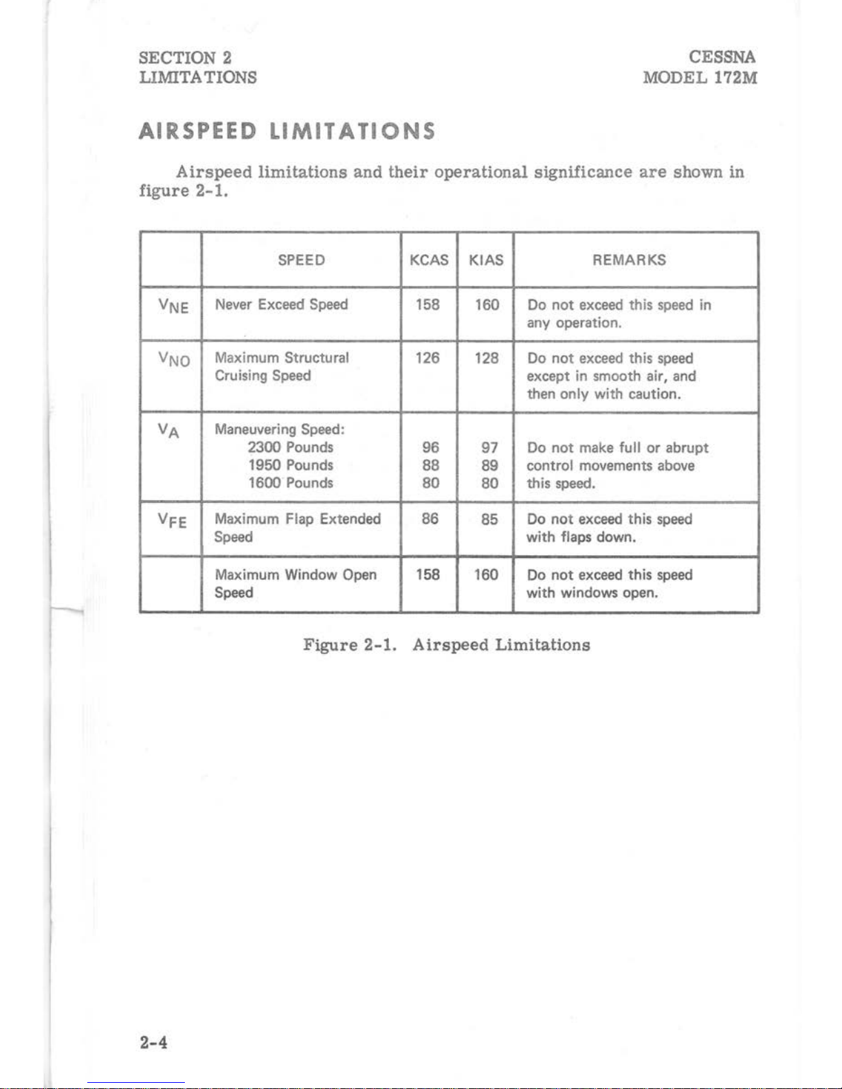
Airspeed
limitations
and
their
operational
significance
are
shown in
figure
2-1.
SPEED
KCAS KIAS
REMARKS
VNE
Never Exceed
Speed
158
160 Do
not
exceed
this
speed
in
any operation.
VNO
Maximum Structural
126 128
Do
not
exceed
this
speed
Cruising
Speed
except in smooth air, and
then only
with
caution.
VA
Maneuvering
Speed:
2300 Pounds
96
97
Do
not
make
full
or
abrupt
1950 Pounds
88
89
control movements
above
1600Pounds
80
80
this
speed.
VFE
Maximum Flap Extended
86
85
Do
not
exceed
this
speed
Speed
with
flaps down.
Maximum Window
Open 158 160 Do
not
exceed this
speed
Speed
with
windows open.
Figure
2-1.
Airspeed
Limitations
2-4

CESSNA
MODEL
172M
SECTION 2
LIMITATIONS
AIRSPEED
INDICATOR
MARKINGS
Airspeed
indicator
markings
and
their
color
code
significance
are
shown
in
figure
2-2.
MARKING
KIAS
VALUE
SIGNIFICANCE
OR
RANGE
White Arc
41-85
Full Flap Operating
Range.
Lower
limit
is
maximum weight
Vs0 in
landing configuration.
Upper
limit
is
maximum
speed
permissible
with
flaps extended.
Green Arc
47-
128
Normal Operating
Range.
Lower
limit
is
maximum weight
Vs
with
flaps retracted. Upper
limit
is
maxi-
mum
structural cruising
speed.
Yellow Arc
128-
160 Operations must
be
~onducted
with
caution
and
only
in smooth air.
Red
Line 160
Maximum
speed
for
all operations.
Figure
2-2.
Airspeed
Indicator
Markings
POWER
PLANT
LIMITATIONS
Engine
Manufacturer:
Avco
Lycoming.
Engine
Model
Number:
0-320-E2D
.
Engine
Operating
Limits
for
Takeoff
and
Continuous
Operations:
Maximum
Power:
150 BHP.
Maximum
Engine
Speed: 2700 RPM.
NOTE
The
static
RPM
range
at
full
throttle
(carburetor
heat
off)
is
2300 to 2420 RPM.
Maximum
Oil
Temperature:
l18°C
(245°F).
Oil
Pressure,
Minimum:
25
psi.
Maximum:
100
psi.
Propeller
Manufacturer:
McCauley
Accessory
Division.
Propeller
Model
Number:
1C160/DTM7553.
Propeller
Diameter,
Maximum:
7 5
inches.
Minimum:
74
inches.
2-5
SECTION 2
LIMITATIONS
CESSNA
MODEL 172M
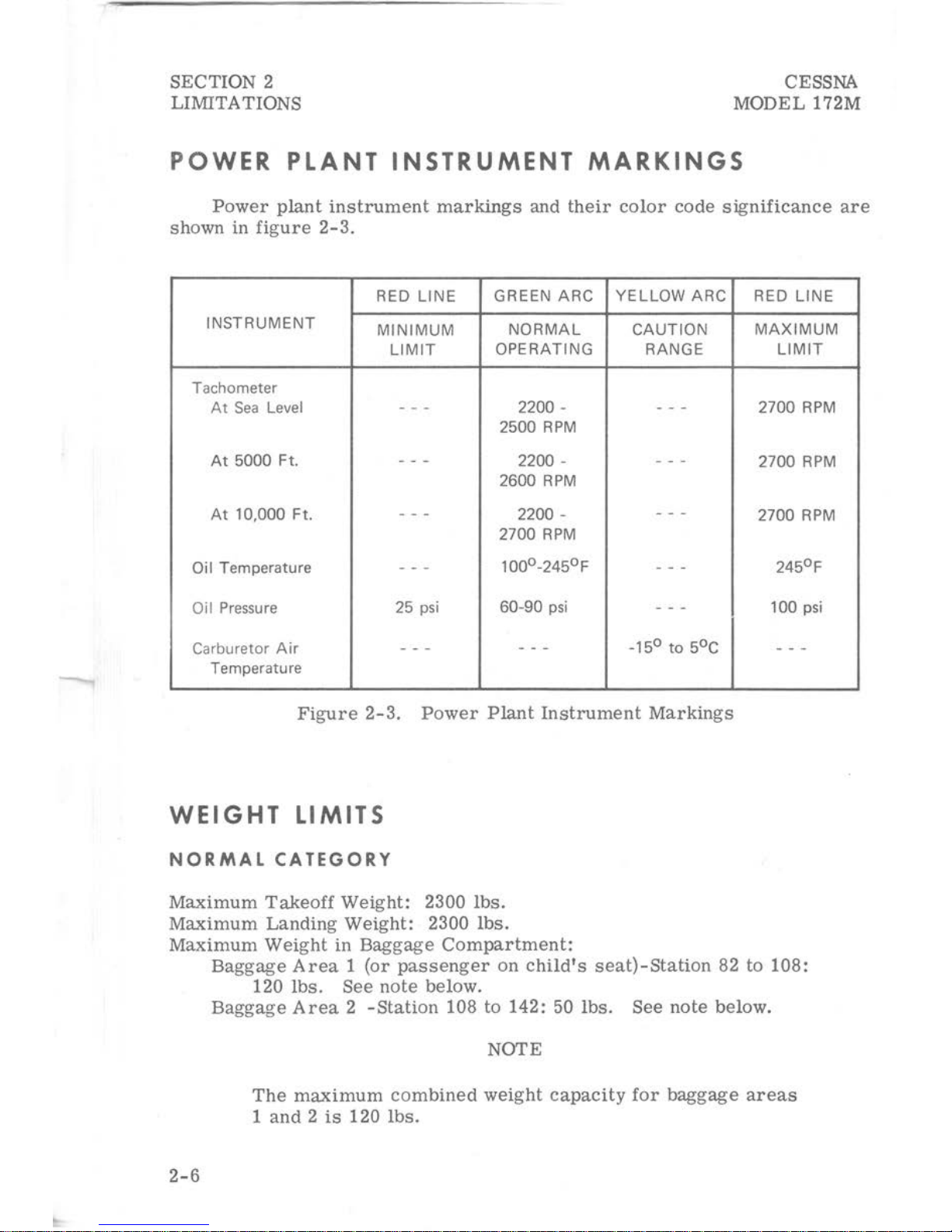
POWER
PLANT
INSTRUMENT
MARKINGS
Power
plant
instrument
markings
and
their
color
code
significance
are
shown in
figure
2-3.
RED LINE
GREEN ARC YELLOW ARC
INSTRUMENT
MINIMUM
NORMAL
CAUTION
LIMIT
OPERATING
RANGE
Tachometer
At
Sea
Level
- - -
2200-
- - -
2500
RPM
At
5000 Ft. - - -
2200-
- - -
2600
RPM
At
10,000 Ft.
-
- -
2200-
- - -
2700
RPM
Oil Temperature
- - -
100°-245°F
- - -
Oil
Pressure
25
psi
60-90
psi
- - -
Carburetor
Air
- - -
- - -
-15°
to
5°C
Temperature
Figure
2-3.
Power
Plant
Instrument
Markings
WEIGHT
LIMITS
NORMAL CATEGORY
Maximum
Takeoff
Weight:
2300
lbs.
Maximum
Landing
Weight:
2300
lbs.
Maximum
Weight
in
Baggage
Compartment:
RED LINE
MAXIMUM
LIMIT
2700
RPM
2700
RPM
2700
RPM
245°F
100
psi
- - -
Baggage
Area 1 (or
passenger
on
child's
seat)-Station
82 to
108:
120
lbs.
See
note
below.
2-6
Baggage
Area 2 -Station
108 to 142: 50
lbs.
See
note
below.
NOTE
The
maximum
combined
weight
capacity
for
baggage
areas
1
and 2 is
120
lbs.
CESSNA
MODEL 172M
UTILITY
CATEGORY
Maximum
Takeoff Weight: 2000
lbs.
Maximum
Landing Weight: 2000
lbs.
SECTION 2
LIMITATIONS
Maximum
Weight
in
Baggage
Compartment:
In
the
utility
category,
the
baggage
compartment
and
rear
seat
must
not
be
occupied.
CENTER
OF
GRAVITY
LIMITS
NORMAL
CATEGORY
Center
of
Gravity
Range:
Forward:
35. 0
inches
aft of
datum
at
1950
lbs.
or
less,
with
straight
line
variation
to 38. 5
inches
aft
of
datum
at
2300
lbs.
Aft:
47. 3
inches
aft
of
datum
at
all
weights.
Reference
Datum:
Front
face
of
firewall.
UTILITY
CATEGORY
Center
of
Gravity
Range:
Forward:
35. 0
inches
aft of
datum
at
1950
lbs.
or
less,
with
straight
line
variation
to 35. 5
inches
aft
of
datum
at
2000 lbs.
Aft:
40. 5
inches
aft
of
datum
at
all
weights.
Reference
Datum:
Front
face
of
firewall.
MANEUVER
LIMITS
NORMAL
CATEGORY
This
airplane
is
certificated
in both the
normal
and
utility
category.
The
normal
category
is
applicable
to
aircraft
intended
for
non-aerobatic
operations.
These
include
any
maneuvers
incidental
to
normal
flying,
stalls
(except
whip
stalls)
and
turns
in which the
angle
of
bank
is
not
more
than 60°.
UTILITY
CATEGORY
This
airplane
is
not
designed
for
purely
aerobatic
flight.
However,
in the
acquisition
of
various
certificates
such
as
commercial
pilot,
instru-
ment
pilot
and
flight
instructor, certain
maneuvers
are
required
by the
FAA.
All
of
these
maneuvers
are
permitted
in
this
airplane
when
oper-
ated
in the
utility
category.
In the
utility
category,
the baggage
compartment
and
rear
seat
must
2-7
SECTION 2
LIMITATIONS
CESSNA
MODEL
172M
not
be
occupied.
ed
below:
No
aerobatic
maneuvers
are
approved
except
those
list-
MANEUVER
Chandelles
.
Lazy
Eights
Steep
Turns
Spins
..
.
Stalls
(Except
Whip
Stalls).
RECOMMENDED ENTRY SPEED*
105
knots
105 knots
95
knots
Slow
Deceleration
Slow
Deceleration
*Abrupt
use
of
the
controls
is
prohibited
above
97
knots.
Aerobatics
that
may
impose
high
loads
should
not
be
attempted.
The
important
thing to
bear
in
mind
in
flight
maneuvers
is
that
the
airplane
is
clean
in
aerodynamic
design
and
will
build
up
speed
quickly
with the
nose
down.
Proper
speed
control
is
an
essential
requirement
for
execution
of
any
maneuver,
and
care
should
always
be
exercised
to
avoid
excessive
speed
which
in
turn
can
impose
excessive
loads
. In the
execution
of
all
maneuvers,
avoid
abrupt
use
of
controls.
Intentional
spins
with
flaps
ex-
tended
are
prohibited.
FLIGHT
LOAD
FACTOR
LIMITS
NORMAL CATEGORY
Flight
Load
Factors
(Gross
Weight
- 2300
lbs.)
*Flaps
Up
..................
+3.8g,
-1.52g
*Flaps
Down . . . . . . . . . . . . . . . . . +3.
Og
*The
design
load
factors
are
150% of
the
above,
and
in
all
cases,
the
structure
meets
or
exceeds
design
loads.
UTILITY
CATEGORY
Flight
Load
Factors
(Gross
Weight - 2000
lbs.)
2-8
*Flaps
Up
. . . . . . . . . . . . . . . . . .
+4.
4g,
-1.
76g
*Flaps
Down . . . . . . . . . . . . . . . . . +3.
Og
*The
design
load
factors
are
150% of
the
above, and in
all
cases,
the
structure
meets
or
exceeds
design
loads.
CESSNA
MODEL
172M
KINDS
OF
OPERATION
LIMITS
SECTION 2
LIMITATIONS
The
airplane
is
equipped
for
day
VFR
and
may
be equipped
for
night
VFR
and/or
IFR
operations.
FAR
Part
91
establishes
the
minimum
re-
quired
instrumentation
and
equipment
for
these
operations.
The
refer-
e
nce
to
types
of
flight
operations
on the
operating
limitations
placard re-
flects
equipment
installed
at
the
time
of
Airworthiness
Certificate
issuance.
Flight
into known
icing
conditions
is
prohibite
d.
FUEL
LIMITATIONS
2
Standard
Tanks:
21
U.S.
gallons
each.
Total
Fuel:
42
U.S.
gallons.
Usable
Fuel
(all
flight
conditions):
38
U.S.
gallons.
Unusable
Fuel:
4. 0
U.S.
gallons.
2 Long Range
Tanks:
26
U.S.
gallons
each.
Total
Fuel:
52
U.S.
gallons.
Usable
Fuel
(all
flight conditions) : 48
U.S. gallons.
Unusable
Fuel:
4. 0
U.S.
gallons.
NOTE
To
ensure
maximum
fuel
capacity
when
refueling,
place
the
fuel
selector
valve
in
either
LEFT
or
RIGHT
posi-
tion to
prevent
cross-feeding.
NOTE
Takeoff
and
land
with
the
fuel
selector
valve
handle
in
the
BOTH
position.
Fuel
Grade
(and
Color):
80/8 7 Minimum
Grade
Aviation
Fuel
(red).
Alternate
fuels
which
are
also
approved
are:
100/130
Low
Lead
AVGAS (green). (Maximum
lead
content
of 2 cc
per
gallon
. )
100/130
Aviation
Grade
Fuel
(green)
. (Maximum
lead
content
of
4. 6
cc
per
gallon.
)
NOTE
When
substituting
a hi
gher
octane
fuel,
low
lead
AVGAS
100
should
be
used
whenever
possible
since
it
will
result
in
less
lead
contamination
of the engine.
2-9

SECTION 2
LIMITATIONS
PLACARDS
CESSNA
MODEL 172M
The
following
information
is
displayed
in
the
form
of
composite
or
individual
placards.
(1)
In
full
view
of
the
pilot:
(The "DA
Y-NIGHT-VFR-IFR"
entry,
shown on
the
example
below,
will
vary
as
the
airplane
is
equipped.)
This
airplane
must
be
operated
in
compliance
with
the
operating
limitations
as
stated
in
the
form
of
placards,
markings,
and
manuals.
--------MAXIMUMS-------Normal
Category
MANEUVERING
SPEED
(lAS)
97
knots
.
GROSS WEIGHT . . . . . 2300
lbs.
FLIGHT LOAD
FACTOR
Flaps
Up
Flaps
Down
+3.8,
-1.52
+3.0
Utility
Category
97
knots
2000
lbs.
+4. 4,
-1.
76
+3.0
Normal
Category -No
acrobatic
maneuvers
including
spins
approved.
Utility
Category
-
Baggage
compartment
and
rear
seat
must
not
be
occupied.
--NO
ACROBATIC MANEUVERS
APPROVED--
EXCEPT
THOSE LISTED BELOW
Maneuver
Chandelles.
Lazy
Eights
Steep
Turns
Recm.
Entry
Speed
. 105
knots
. 105
knots
.
95
knots
Maneuver
SplilS:-
.
Stalls
(except
Recm.
Entry
Speed
Slow
Deceleration
whip
stalls)
Slow
Deceleration
Altitude
loss
in
stall
recovery
--
180
feet.
Abrupt
use
of
controls
prohibited
above
97
knots.
Spin
Recovery:
opposite
rudder -forward
elevator -neutralize
controls.
Intentional
spins
with
flaps
extended
are
prohibited.
Flight
into
known
icing
conditions
prohibited.
This
airplane
is
certified
for
the
following
flight
operations
as
of
date
of
original
airworthiness
certificate:
DAY - NIGHT -
VFR -IFR
2-10

CESSNA
MODEL
172M
(2)
Forward
of
fuel
selector
valve:
BOTH TANKS ON
FOR
TAKEOFF
& LANDING
(3)
On
the
fuel
selector
valve
(standard
tanks):
BOTH-
38 GAL.
ALL
FLIGHT
ATTITUDES
LEFT-
19 GAL.
LEVEL
FLIGHT
ONLY
RIGHT-
19 GAL.
LEVEL
FLIGHT
ONLY
OFF
On the
fuel
selector
valve
(long
range
tanks):
BOTH-
48 GAL.
ALL
FLIGHT
ATTITUDES
LEFT-
24 GAL.
LEVEL
FLIGHT
ONLY
RIGHT-
24 GAL.
LEVEL
FLIGHT ONLY
OFF
(4)
Near
fuel
tank
filler
cap
(standard
tanks):
FUEL
80/87
MIN. GRADE AVIATION GASOLINE
CAP.
21 U.S. GAL.
Near
fuel
tank
filler
cap
(long
range
tanks):
FUEL
8
0/87
MIN. GRADE AVIA
TION
GASOLINE
CAP.
26
U.S
. GAL.
SECTION
2
LIMITATIONS
2-11
SECTION
2
LIMITATIONS
2-12
(5)
Near
flap
indicator:
AVOID
SLIPS
WITH
FLAPS
EXTENDED
(6)
In baggage
compartment:
120
POUNDS MAXIMUM
BAGGAGE
AND/OR
AUXILIARY PASSENGER
FORWARD
OF
BAGGAGE DOOR LATCH
50 POUNDS MAXIMUM
BAGGAGE
AFT
OF
BAGGAGE DOOR
LATCH
MAXIMUM
120
POUNDS COMBINED
FOR
ADDITIONAL LOADING INSTRUCTIONS
SEE
WEIGHT AND BALANCE DATA
(7)
On
the
instrument
panel
near
over-voltage
light:
HIGH VOLTAGE
CESSNA
MODEL
172M
CESSNA
MODEL 172M
SECTION 3
EMERGENCY
PROCEDURES
SECTION
3
EMERGEN
CY
PROCEDURES
TABLE OF
CONTENTS
Page
Introduction
. . . . . . . .
Airspeeds
For
Safe
Operation
OPERATIONAL CHECKLISTS
Engine
Failures
. . . . . . . . . . . . . .
Engine
Failure
During
Takeoff
Run . . . .
Engine
Failure
Immediately
After
Takeoff
.
Engine
Failure
During
Flight
. . . . . .
Forced
Landings
. . . . . . . . . . . . . .
Emergency
Landing Without
Engine
Power
Precautionary
Landing With
Engine
Power
Ditching
. . . . . . . . . . . . .
Fires
. . . . . . . . . . . . . . . .
Engine
Fire
During
Start
On
Ground
Engine
Fire
In
Flight
. .
Electrical
Fire
In
Flight
Cabin
Fire
Wing
Fire
......
.
Icing
. . . . . . . .
..
.
Inadvertent
Icing
Encounter
. . . .
Static
Source
Blockage
(Erroneous
Instrument
Reading
Suspected)
. . . . . . . . . . . . .
Landing
With A Flat
Main
Tire
. . . . . .
Electrical
Power
Supply
System
Malfunctions
Over-
Voltage
Light
Illuminates
Ammeter
Shows
Discharge
. . . . . .
Engine
Failure
.
Forced
Landings
AMPLIFIED
PROCEDURES
3-3
3-3
3-3
3-3
3-3
3-4
3-4
3- 4
3-4
3-5
3- 5
3-5
3-6
3-6
3-6
3-7
3- 7
3-7
3-8
3-8
3-8
3-8
3-8
3-9
3
-10
3-1
SECTION 3
EMERGENCY
PROCEDURES
TABLE
OF
CONTENTS
(Continued)
Landing Without
Elevator
Control
. . . . . . . . . . .
Fires
......................
.
Emergency
Operation
In
Clouds
(Vacuum
System
Failure).
Executing
A 180°
Turn
In
Clouds
. .
Emergency
Descent
Through
Clouds
Recovery
From A Spiral
Dive
Flight
In Icing
Conditions
. . . . . . .
Static
Source
Blocked
. . . . . .
Spins
. . . . . . . . .
......
.
Rough
Engine
Operation
Or
Loss
Of
Power
Carburetor
Icing
. .
Spark
Plug
Fouling
. . . . . . . . .
Magneto
Malfunction
. . . . . . . .
Low
Oil
Pressure
. . . . . . . . .
Electrical
Power
Supply
System
Malfunctions
Excessive
Rate
Of
Charge
.
Insufficient
Rate
Of
Charge
. . . . . .
3-2
CESSNA
MODEL 172M
Page
3-10
3-10
3-11
3-11
3-11
3-12
3-12
3-12
3-13
3-13
3-13
3-14
3-14
3-14
3-15
3-15
3-15
CESSNA
MODEL
172M
SECTION 3
EMERGENCY
PROCEDURES
INTRODUCTION
Section 3 provides
checklist
and
amplified
procedures
for
coping
with
emergencies
that
may
occur.
Emergencies
caused
by
airplane
or
engine
malfunctions
are
extremely
rare
if
proper
preflight
inspections
and
main-
tenance
are
practiced.
Enroute
weather
emergencies
can
be
minimized
or
eliminated
by
careful
flight
planning
and
good
judgement
when
unexpect-
\
ed
weather
is
encountered. However,
should
an
emergency
arise
the
basic
guidelines
described
in
this
section
should
be
considered
and
applied
as
necessary
to
correct
the
problem.
Emergency
procedures
associated
with
the
ELT
and
other
optional
systems
can
be
found
in
Section
9.
AIRSPEEDS FOR SAFE
OPERATION
Engine
Failure
After
Takeoff:
Wing
Flaps
Up . .
Wing
Flaps
Down .
Maneuvering
Speed:
2300
Lbs
1950
Lbs
1600
Lbs
Maximum
Glide:
2300
Lbs
Precautionary
Landing
With
Engine
Power
Landing Without
Engine
Power
:
Wing
Flaps
Up . .
Wing
Flaps
Down . . . . .
OPERATIONAL
CHECKLISTS
ENGINE
FAILURES
ENGINE
FAILURE
DURING
TAKEOFF
RUN
(1)
Throttle
--
IDLE.
(2)
Brakes--
APPLY.
(3)
Wing
Flaps
--
RETRACT .
(4)
Mixture --IDLE
CUT-OFF.
(5)
Ignition Switch --OFF.
ENGINE
FAILURE
IMMEDIATELY
AFTER
TAKEOFF
(1)
Airspeed
--
65
KIA
S (flaps UP ).
60
KIAS
(flaps DOWN).
65 KIAS
60 KIAS
97 KIAS
89 KIAS
80
KIAS
65 KIAS
60 KIAS
65 KIAS
60 KIAS
3-3
SECTION 3
EMERGENCY
PROCEDURES
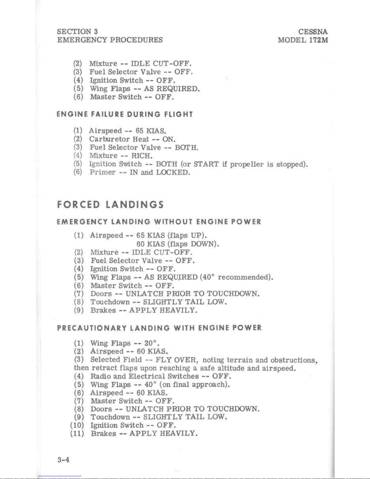
(2)
Mixture
--
IDLE
CUT-OFF.
(3)
Fuel
Selector
Valve --OFF.
(4)
Ignition
Switch --OFF.
(5) Wing
Flaps
--AS
REQUIRED.
(6)
Master
Switch--
OFF.
ENGINE
FAILURE
DURING
FLIGHT
(1)
Airspeed
--
65
KIAS.
(2)
Carburetor
Heat --ON.
(3)
Fuel
Selector
Valve --BOI'H.
(4)
Mixture --RICH.
CESSNA
MODEL 172M
(5)
Ignition Switch --BOI'H
(or
START
if
propeller
is
stopped).
(6)
Primer
--
IN
and
LOCKED.
FORCED
LANDING
,S
EMERGENCY
LANDING
WITHOUT
ENGINE
POWER
(1)
Airspeed--
65 KIAS
(flaps
UP).
60 KIAS
(flaps
DOWN).
(2)
Mixture
--
IDLE
CUT-OFF.
(3)
Fuel
Selector
Valve --OFF.
(4)
Ignition
Switch --OFF.
(5) Wing
Flaps
--AS
REQUIRED (40°
recommended).
(6)
Master
Switch --OFF.
(7)
Doors
--
UNLATCH
PRIOR
TO
TOUCHDOWN.
(8)
Touchdown--
SLIGHTLY
TAIL
LOW.
(9)
Brakes--
APPLY
HEAVILY.
PRECAUTIONARY
LANDING
WITH
ENGINE
POWER
(1) Wing
Flaps
--
20°.
3-4
(2)
Airspeed
--
60 KIAS.
(3)
Selected
Field
--
FLY
OVER,
noting
terrain
and
obstructions,
then
retract
flaps
upon
reaching a safe
altitude
and
airspeed.
(4)
Radio
and
Electrical
Switches--
OFF.
(5) Wing
Flaps--
40° (on
final
approach).
(6)
Airspeed--
60 KIAS.
(7)
Master
Switch --OFF.
(8)
Doors--
UNLATCH
PRIOR
TO
TOUCHDOWN.
(9)
Touchdown--
SLIGHTLY
TAIL
LOW.
{10)
Ignition
Switch --OFF.
(11)
Brakes--
APPLY
HEAVILY.
CESSNA
MODEL
172M
SECTION 3
EMERGENCY
PROCEDURES
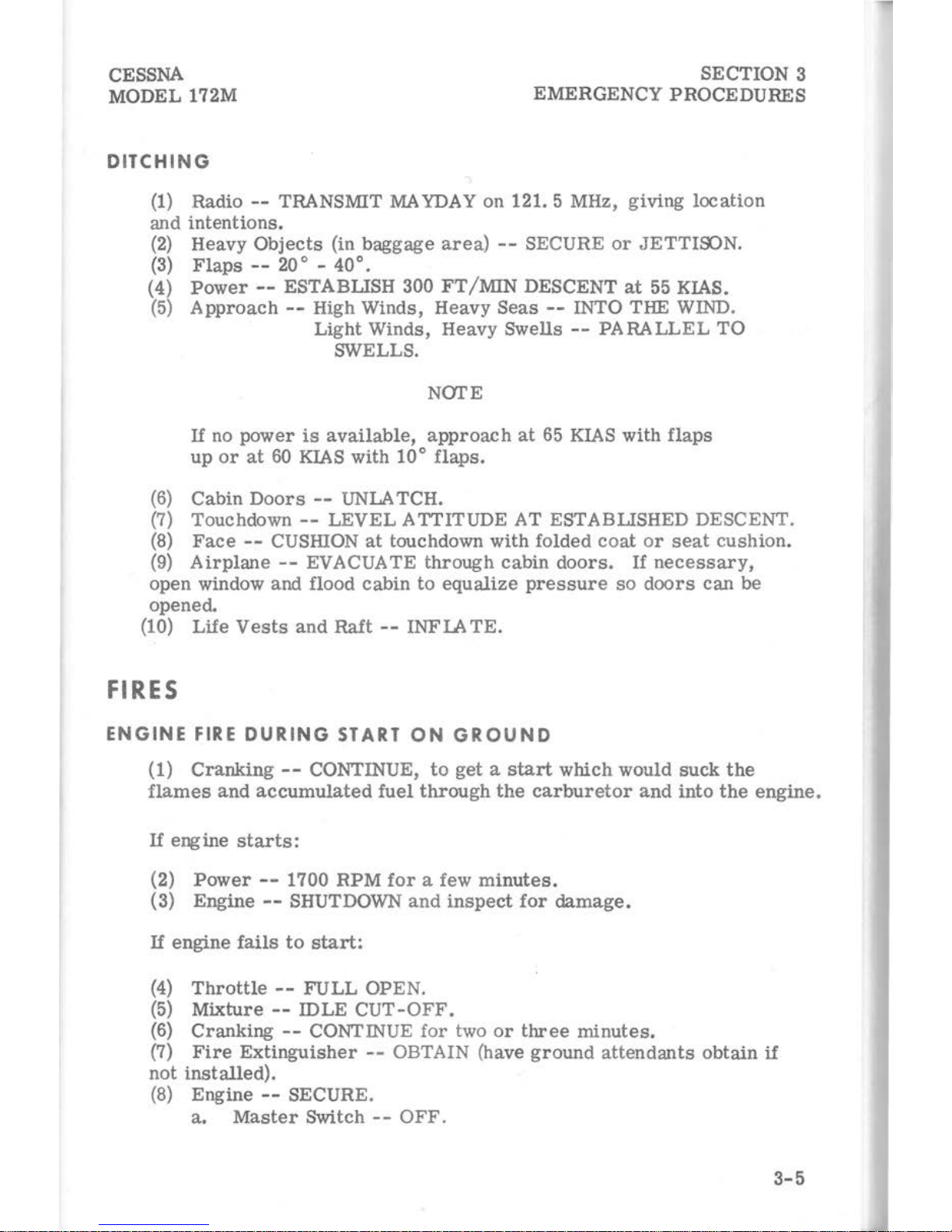
DITCHING
(1)
Radio --TRANSMIT MAYDAY on 121. 5 MHz, giving
location
and
intentions.
(2)
Heavy
Objects
(in
baggage
area)
--
SECURE
or
JETTIOC>N.
(3)
Flaps --20
o -
40°.
(4)
Power--
ESTABLISH
300FT/MIN
DESCENT
at
55 KIAS.
(5)
Approach --High Winds,
Heavy
Seas --INTO THE WIND.
Light
Winds, Heavy Swells --PARALLEL
TO
SWELLS.
NOTE
If no
power
is
available,
approach
at
65 KIAS
with
flaps
up
or
at
60 KIAS with
10°
flaps.
(6)
Cabin
Doors
--
UNLATCH.
(7)
Touchdown--
LEVEL
ATTITUDE AT ESTABLISHED DESCENT.
(8)
Face
--
CUSHION
at
touchdown
with
folded
coat
or
seat
cushion.
(9)
Airplane--
EVACUATE
through
cabin
doors.
If
necessary,
open
window and flood
cabin
to
equalize
pressure
so
doors
can
be
opened.
(10) Life
Vests
and
Raft --INFI.A
TE.
FIRES
ENGINE
FIRE
DURING
START
ON
GROUND
(1)
Cranking--
CONTINUE,
to
get a start
which
would
suck
the
flames
and
accumulated
fuel
through
the
carburetor
and
into
the
engine.
If
engine
starts:
(2)
Power
--
1700 RPM
for
a few
minutes.
(3) Engine --SHUTDOWN
and
inspect
for
damage.
If
engine
fails
to
start:
(4)
Throttle
--
FULL
OPEN.
(5)
Mixture--
IDLE
CUT-OFF.
(6)
Cranking
--
CONTINUE
for
two
or
three
minutes.
(7)
Fire
Extinguisher
--
OBTAIN (have
ground
attendants
obtain
if
not
installed).
(8) Engine
--
SECURE.
a.
Master
Switch --OFF
.
3-5
SECTION 3
CESSNA
MODEL
172M EMERGENCY PROCEDURES
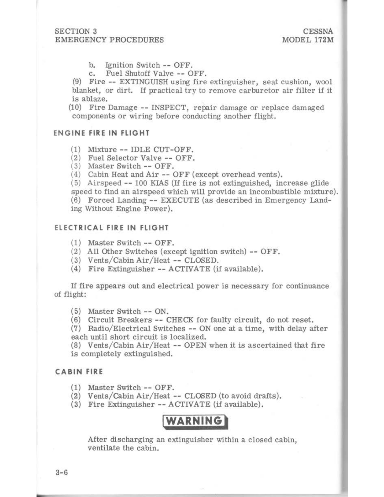
b. Ignition Switch --OFF.
c.
Fuel
Shutoff Valve --OFF.
(9)
Fire
--
EXTINGUISH
using
fire
extinguisher,
seat
cushion,
wool
blanket,
or
dirt.
If
practical
try
to
remove
carburetor
air
filter
if
it
is
ablaze.
(10)
Fire
Damage --INSPECT,
repair
damage
or
replace
damaged
components
or
wiring
before
conducting
another
flight.
ENGINE
FIRE
IN
FLIGHT
(1)
Mixture --IDLE
CUT-OFF.
(2)
Fuel
Selector
Valve--
OFF.
(3)
Master
Switch--
OFF.
( 4) Cabin
Heat
and
Air
--
OFF
(except
overhead
vents).
(5)
Airspeed--
100
KIAS
(If
fire
is
not
extinguished,
increase
glide
speed
to
find
an
airspeed
which
will
provide
an
incombustible
mixture).
(6)
Forced
Landing --EXECUTE
(as
described
in
Emergency
Land-
ing
Without
Engine
Power).
ELECTRICAL FIRE
IN
FLIGHT
(1)
Master
Switch--
OFF.
(2)
All
Other
Switches
(except
ignition
switch) --OFF.
(3)
Vents/Cabin
Air/Heat
--
CLOSED.
(4)
Fire
Extinguisher
--ACTIVATE
(if
available).
If
fire
appears
out
and
electrical
power
is
necessary
for
continuance
of
flight:
(5)
Master
Switch--
ON.
(6)
Circuit
Breakers
--
CHECK
for
faulty
circuit,
do
not
reset.
(7)
Radio/Electrical
Switches --ON one
at a time,
with
delay
after
each
until
short
circuit
is
localized.
(8)
Vents/Cabin
Air/Heat
--
OPEN
when
it
is
ascertained
that
fire
is
completely
extinguished.
CABIN
FIRE
3-6
(1)
Master
Switch --OFF.
(2)
Vents/Cabin
Air/Heat
--
CLOSED
(to
avoid
drafts).
(3)
Fire
Extinguisher--
ACTIVATE
(if
available).
IWARNINGl
After
discharging
an
extinguisher
within a
closed
cabin,
ventilate
the
cabin.
 Loading...