

Cessna 172, SKYHAWK Ownersmanual

" LOOK FOR
THE
AND
BLUE CESSNA
PENNANTS
FOR THAT EXTRA SERVICE
WHERE
IT
COUNTS WHEN
YOU
NEED IT".
CESSNA AIRCRAFT COMPANY WICHITA, KANSAS
MODEL
7~
AND
SKYHAWK
OWNER'S
MANUAL

PERFORMANCE
and
SPECIFICATIONS
GROSS WEIGHT . . . . .
SPEED:
T
op
Speed
at
Sea Level
.
Cruise,
75%
Po
wer
at
7000
ft
.
RANGE:
Cruise,
75%
Power
at
7000
ft
39
Gal.
No R
eserve
Optimum
Range at
10,
000
ft.
39
Gal
. No
Reserve
RATE
-OF-CLIMB
AT
SEA
LEVEL
. • •
SERVICE
CEILING .
TAKE-OFF
:
Ground
Run
. • • .
••.••
T
otal
Distance
Over
50
Foot
Obstacle
LANDING.
Land
ing
Roll
. . . . . . . . . • .
Total
Dis
tan
ce
Over
50
Foot
Obstacle
EMPTY
WEIGHT
(Approximate)
.
BAGGAGE .
........
. .
WING LOADING:
Pounds/Sq
Foot
POWER
LOADING: Po
unds/HP
FUEL
CAPACITY: T
ota
l
OIL
CAPACITY: To
tal
.
PROPELLER
D~A
METER
PROPELL
ER
TYPE
POWER:
Continental Engine
No.
Horse Power
. . . .
172
2300 l
bs
13
8
mph
130
mp
h
595
miles
4. 6
hours
130
mph
720
miles
7.1
hours
102
mph
645
fpm
13,
100
ft
865
ft
1525
ft
• 520
ft
1250
ft
• •
1260
lbs
• 120
lbs
13.2
15.9
42
gal.
8
qts
76
in.
Fixed
Pitch
0-300-C
*
145
SKYHAWK
2300
lbs
139
mph
131
mph
600
mile
s
4.
6 hou
rs
131 mph
720
mil
es
'l.
1
hour
s
102
mph
645
fpm
1
3,
100
rt
865
fl
1525
ft
520
ft
1250
fl
13
30
l
bs
120
lbs
13 .. 2
1
5.9
42
gal.
8
qt
s
76
in.
Fix
ed
Pit
ch
0-300
-1)
145
•
nie
Model
Fl
72,
which
Is
manufactured
by
Rei.ms A
viation
S.
A.
Re
ims
(Marne) France
1s
identical
to
the
172
except
that
U
is
powered
by
an
0-300-D
engin~
,
manufactured under
iJ~cn.
~
··
by Rolls
Roy
ce,
Crew
e,
England.
All
172
information
in
this
manual
pertains
to
th
e
F172
:is
well.
02()'}.13
(RGl-
10().1/
0l)
COPYRI
GHT e 191M
Cessna Aircraft Company
Wichita, Kansas
USA
CONGRATULATIONS
.....
...
.
Welcome
to
the
ranks
of
Cessna
owners!
Your
Cessna
has
been
designed
and
constructed
to
give
you
the
most
in
performance,
economy,
and
com
-
fort.
It
is
our
desire
that
you
will
find flying
it,
either
for
business
or
pleasure, a pleasant
and
profitable
experience.
This
Owner's
Manual
has
been
prepared
as a guide
to
help you
get
the
most pl
easure
and
utility
from
your
172.
It
contains
information
about
yo
ur
Cessna's equipment, operating procedures, and
performance;
and
suggestions
for
its
servicing
and
care.
We
urge
you
to
read
it
from
cover
to
cover,
and
to
refer
to
it
frequently.
Our
interest
in
your flying
ple
asure has
not
ceased
with
your
purchase
of
a
Cessna. World-wide,
the
Cessna
Deal
er Organization
backed
by
the
Cessna
Service Department
stands ready
to
serve
you.
The
following
services
are
offered
by
most
Cessna
Dealers:
FACTORY TRAINED MECHANICS to
provide
you
with
courteous
expert
service.
FACTORY
APPROVED
SERVICE EQUIPMENT
to
provide
you
wit
h t
he
most
effic
ient
and
accurate
workmanship
possible.
A STOCK
OF
GENUINE CESSNA SERVICE
PARTS
on
hand
when
you
need them
.
THE
LATEST AUTHORITATIVE INFORMATION FOR SER
V-
ICING CESSNA AIRPLANES,
since
Cessna
Dealers
have
all
of
the Serv
ice
Manuals
and
Parts
Catalogs,
kept
current
by
Service
Letters
and
Service
News
Letters
published
by
Cessna
Aircraft
Company.
We
urge
all
Cessna
owners
to
use
the
Cessna
Dealer
Organization
to
the
fullest.
A
current
Cessna
Dealer
Dire
ctory
accompanies
your
new
airplane. The
Director y
is
revised
frequently,
and a current
copy
can
be
obtained
from
your
Cessna
Dealer
. Make
your
Directory
one
of
your cross-
country
flight
planning
aids; a warm
welcome
awaits
you
at
every
Cessna
Dealer.

ii
so
-20·.o ..
-
------
t-o--
11
' .4
··-
___,
* M
aximum
beighl
of
._irpW>e
"''Ill
nose gear
~pressed
aod an
opc.-
loaal
rotallilg
be;u:on
lnsUlled
.
PRINCIPAL
DIMENSIONS
.
____
q~~
-~
and
Skyhawk
t--
----
-
---
36".1"---
--
- - -
---..1
TABLE
OF
CONTENTS
============================================Pag
e
==
SECTION
I -
OPERATING
CHECK
LIST
..............
1-1
SECTION
II -
DESCRIPTION
AND
OPERATING
DETAILS
...................... 2-1
SECTION
Ill -OPERATING
LIMITATIONS
............. 3-1
SECTION
IV-
CARE
OF
THE
AIRPLANE
............ 4-1
OWNER
FOLLOW-UP
SYSTEM
...........................
4-
s
SECTION
V -
OPERATIONAL
DATA
...................... 5
-1
SECTION
VI -OPTIONAL
SYSTEMS
...................... 6 -1
ALPHABETICAL
INDEX
........................................ l
ndex
-1
ill
CD
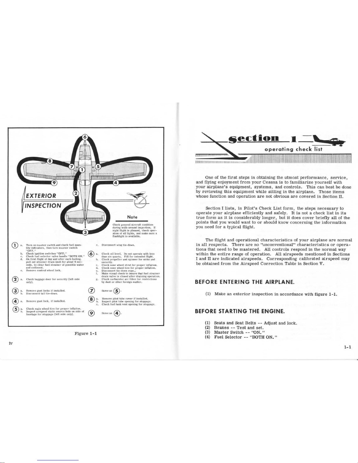
a.
Tarn
on
master
switch
a.nd
cltec.k
ft1e-
l
qm.n-
hty
lnclicators,
tbea
turn m11,.ster swit<b.
-
oIT.
00
b.
Ctieck
ignition
switches
,..OFF
."
c. Cllecl<
fuel
selector
vat
...
hmdle
" BOTH
ON_
••
d.
On
f!rsl
rught
et!
day
aod
alter
eaeh
lueli~.
p.tll
out
stn..iner
drain
knob
f
or
:about
4
sec-
onds.
to
clear
fuel
sll'2i
ner
ot
possible
r.tter
and
sediment.
e.
RemOTe
control
..tied
lock.
@
··
(.i\
a.
'\::?/
b.
Check
bag;:age
door
for
sec.wily (left
side
oaly).
Removr
gust
locks
if
lnslalled.
01.sconnect
b:tl
tl~doNtt.
Remove
pst
lock,
If
lnsialled.
Cbeck
main
wheel
tue
for
pl"oper
infiatioo.
Inspect
airspeed
static
source
hole
on
SJde
ol
lusebge
for
stopP3:1:e
(left
stde
only).
No
te
Cbeck.
general
aircn!l
condition
during
walk-arowxl
lnspcctlOll.
U
rught
fllgl!l
is
planned,
cbect
oper-
atioa
ol
all
lights,
and
make
sure
a
fi2Sbliglrt
is
anllallle.
c.
Oisooonect
wlng
Ue-da...n.
16"'
a.
Check
ml
level.
Do
net
"!"'rate
...
tb
less
~
than
six
quan.s.
FUI
for
exiended
llighl.
<i)
b.
Check
propeller
and
spinaer
for
alcks
and
ucur!ty.
c.
Cbeck
nose
wheel
strut
(or
proper
ud'btJoo.
d.
Check
nose
wbeel
tire
for
proper
infla.liort.
e.
DlSCOCllltt.t
Ue-down
rope.,.
r.
.}fake
vtSUa.I
check
to
insare
that
foe!
str.1iner
dn.in
v.llve
is
clOISed a.ner dr.l.inlng ope.r.al1oa.
g.
Check
carburl!'tor
alr
[llter
for
restrtchons
by
dust
or
other
foreJgn matter.
Same
as
@·
®
~b.-
Remove
pilot
tube
coorer tf lnst:all<!d.
Inspect
pilot
tube
opening
for
stoppage.
c.
Check
fuel
lank
<enl
,,._,ing
!or
stoppage.
®
Sameas
@}
Figure
1
-1
iv
I -,
~~iiilP-
One of
the
first
steps
in
obtaining
the
utmost
performance,
service,
and
flying
enjoyment
from
your
Cessna
is
to
familiarize
yourself
with
your
airplane's
equipment, systems,
and
controls.
This
can
best
be
done
by
reviewing
this
equipment
while
sitting
in
the
airplane.
Those
items
whose function and
operation
are
not
obvious
are
covered
in
Section
II.
Section I lists, in
Pilot's
Check
List
form,
the
steps
necessary
to
operate
your
airplane
efficiently
and
safely
.
It
is
not a
check
list
in
its
true
form
as
it
is
considerab
ly
longer,
but
it
does
cover
briefly
all
of
the
points
that
you would
want
to
or
should
K.now
concerning
the
informati
on
you
need
for a typical
flight.
The
flight
and ope
rational
characteristics
of
your
airplane
are
normal
in
all respec
ts.
There
are
no
"unconventional"
characteristics
or
opera-
tions
that
need
to
be
mastered.
All
controls
respond
in
the
normal
way
within the
entire
range
of
operation. All
airspeeds
mentioned
in
Sections
I
and
II
are
indicated airspeeds. Corresponding
calibrated
airspeed
may
be
obtained
from
the
Airspeed
Correction
Table
in
Secti
on
V.
BEFORE
ENTERING
THE
AIRPLANE.
(1)
Make
an
exterior
inspection
in acco
rdance
with
figure
1-1.
BEFORE
STARTING
THE
ENGINE.
{l)
Seats
and
Seat
Belts --Adjust
and
lock
.
(2)
Brakes
- -
Test
and
set.
(3)
Master
Switch --''ON. "
(4)
Fuel
Selector --"BO
TH
ON."
1-1

STARTING T
HE
ENGINE.
(1)
Carbureto
r Heat --Co
ld.
(2)
Mixture
- -
Rich.
(3) P
rime
r - - As
required
.
(4)
Ignition
Switch --"BO
TH.
"
(5) T
hrottle --Open
1/8".
(6)
Propeller
Area --Clear.
(7)
Starter --Engage.
BEFORE TAKE-OFF.
(1) T n
rottle
Setting --1600
RPM.
(2) E
ngine
Instruments
- -
Within
green
arc
and
generator light
out.
(3)
Magnetos
- -
Chec
k (75
RPM
maxim
um
differential
between
mag
-
netos)
.
(4)
Carburetor
Heat --Cneck.
(5) Flight
Controls
- -
Cneck.
(6)
Trim
Tab
- - "T
AKE-OFF."
(7)
Cabin
Doors
- -
Closed
and locked
.
(8). F
lightlnstruments
and
Radios
- -
Set.
TAKE-OFF.
NORMAL
T.AKE-OFF
.
(1)
Wing
Flaps --0°
(2)
Carburetor
Heat --Cold.
(3)
Power
- -
Full
thro
ttle (applied
smoothly).
(4)
Elevator
Control
- -
Lift
nosewheel at
60
MPH.
(5)
Climb
Speed
- - 85 MPH.
MAXIMUM
PERFORMANCE TAKE-OFF
.
1-2
(1)
Wing
Flaps --0°
(2)
Carburetor
Heat --Cold.
(3)
Brakes
- -
Apply
.
(4)
Power
- -
Full
throttle.
(5)
Brakes
- -
Release.
(6)
Elevator
Control
- -
Slightly
tail
low.
(7)
Climb
Speed
- - 65
MPH
(with
obstacles
ahead).
CL1MB.
N
ORMAL
CLIMB.
(1}
Airspeed --80
to
90
MPH
.
(2)
Power --Fu
ll
throttle
.
(3)
Mixture
-- Fu
ll
rich
(unless
engine
is
rough)
.
MAXIMUM
PERFORMANCE
CLIMB
.
(1)
Airspeed
- -
80
MPH
at
sea
level to
17
MPH
at
10,
000
feet.
(2)
Power --Full
throttle.
(3)
Mixture --Full
rich
(unless
engine
is
rough.
CRUISING.
(1)
Power --2200
to
2700 RPM.
(2)
Trim
Tab --Adjust.
(3)
Mixture --Lean.
LET-DOWN.
(1)
Mixture --Rich.
(2)
Power --As
desired.
(3)
Carburetor
Heat
--
As
required
to prevent
carburetor icing.
BEFORE
LANDING
.
(1)
Fuel
Selector --"BOTH ON. "
(2)
Mixture
- - Ri
ch.
(3)
Airspeed --70 -80 MPH
(flaps
up).
(4)
Carburetor
Heat --Apply
before
closing
tnrottle.
(5)
Flaps --As
desired
(below
100
MPH).
(6)
Airspeed --65
to
75
MPH
(flaps
down).
1-3
NORMAL
LANDING.
(1) Touchdown - -
Main wheels
first.
(
2)
Landing Roll --Lower nose
wheel gently
.
(3)
Braking
- -
Minimum
required.
AFTER
LANDING.
(1)
Flaps
- - Up.
(2)
Carbure
tor Heat --Cold
.
SECURE
AIRCRAFT.
1-4
{l}
Mixture --Full lean.
(2) All
Switch
es --"O
FF."
(
3)
Brakes --Set.
(4)
Control
Lock --Installed
.
The
following
paragraphs
describe
the
systems
and
equipment
whose
function
and
operation
is
not
obvious
when
sitting
in
the
airplane.
This
section
also
covers
in
somewhat
greater
detail
some
of
the
items
lis
ted
in
Check
List
form
in
Section
I.
Only
those items
of
the
Check
List
re-
quiring
further
exp
lanation
will
be
found
here.
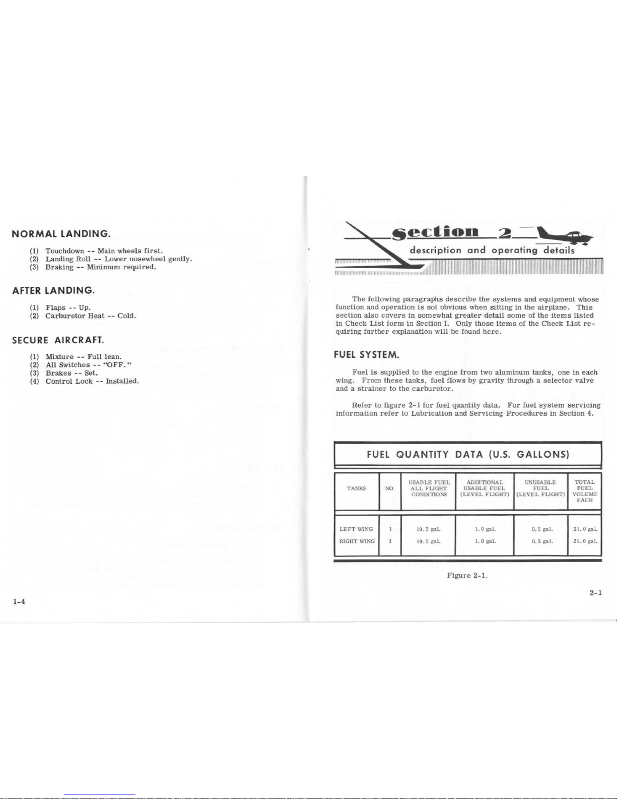
FUEL
SYSTEM
.
Fuel
is
supplied
to
the
engine
from
two
aluminum
tanks,
one
in
each
wing.
From these
tanks,
fuel
flows
by gravity
through a selector
valve
and a strainer
to
the
carburetor.
Refer
to
figure 2-1
for fuel
quantity
data.
For
fuel
system
servicing
information
refer
lo
Lubrication
and
Servi
cing
Procedures
in
Section
4.
FUEL
QUANTITY
DATA
(U.S.
GALLONSt
I
USABLE
FUEL
ADDITIONAL UNUSABLE
TOTAL
TAXKS
00.
ALL
FLIGHT
USABLE
FUEL
FUEL
FUEL
CO?>"D
ITIO!\S
(LEVEL
FLIGHT)
(LEVEL
FLIGHT)
VOLUME
EACH
LEFT
WING
I
19.
5
gal.
1. 0
gal.
0.
5
gal.
21.0gal.
RIGHT
WING
I
19.5
gal.
1.
0
g;a.I.
0. 5 gal.
21.0gal.
Figure 2-1.
2-1

2-2
LEFT
FUEL
TANK
FUEL
SYSTEM
····SCHEMATIC····
FUEL
STRAINER
RIGHT
FUEL
TANK
THROTTLE
CARBURETOR ".,,-
.,,,-
,,'=K)
...__...,.,,,.....---
'',,,
~
TO
-gr.,"G
IN
E
.....
Figure 2-2
MIXTURE
CONT
ROL
KNOB
FUEL
STRAINER DRAIN
KNOB
.
Refer
to
fuel
strainer
servicing
procedures, Section
4.
ELECTRICAL
SYSTEM.
Electrical
energy
is
supplied
by
a
14-
volt,
direct-current
system
powered
by
an
engine-driven
§8R8Pll:!M'
. A
12-volt
storage
battery
is
located
on
the
left-hand
forward
portion
of
the
firewall.
At.-~~
~Q,.
CIRCUIT BREAKERS .
All
electrical
circuits
in
the
airplane,
except
the
clock circuit, are
protected
by
circuit
breakers.
The
clock
has a separate
fuse
mounted
adjacent
to
the
battery.
The
stall
warning
unit,
Oap
position
indicator,
turn
-and-
bank
indicator
and
the
optional
gyro
horizon
test
lights
circuits
are
protected
by a single
automatically
resetting
circuit
breaker
mounted
behind
the
instrument
panel.
The
cigar
light.er.
is
protected
by
a
manually
-
reset
type
circuit
breaker
mounted
directly
on
the
back
of
the
lighter
be-
hind
the
instrument
panel. The
remaining
circuits
are
protected-by
"push
-
to-reset"
breakers
on
the
instrument
panel.
GENERATOR
WARNING
LIGHT.
The
red
generator warning
light
indicates
generator
output.
The
light
remains
off
as
long
as
the
generator
functions
properly.
If a
mal
-
function
interrupts
generator
output,
the
light
will
illuminate.
It
also
will
illuminat
e when
the
battePy
or
external
power
is
on,
before
starting
the
engine,
and
whenever
engine
speed
is
insufficient
to
produce
gen-
erator
output.
The
light
does
not
show
battery
drain
.
LANDING
LIGHTS.
A
three-position,
push-pull
switch
controls
the
optional
landing
lights.
To
turn
one
lamp
on
for
taxiing,
pull
the
switch
out
to
the
filist
stop.
To
turn
both l
amps
on
for
landing,
pull
the
switch
out
to
the
sec-
ond
stop.
2-3
CABIN
HEATING
AND
VENTILATION
SYSTEM .
For
cabin
ventilation,
pull the "CABIN AIR" knob
out.
To
raise
the
air
temperature,
pull
the
"CABIN
HT"
knob
out
approximately 1/4"
to
1/ 2"
for a small
amount
of
cabin
beat.
Additional
heat
is
available
by
pulling
the knob
out
farther;
maximum
heat
is
available
with the "CABIN
HT"
knob
pulled
full
out
and the "CABIN AIR" knob
pushed
full
in. When
no h
eat
is
desired
in
the
cabin, the
"CABIN
HT"
knob
is
pushed
full in.
STARTING ENGINE.
Ordinarily
the
engine
starts
easily
with bne
or
two
strokes
of
the
primer
in
warm
temperatures
to
six
strokes
in
cold
weather,
with the
throttle
open
approximately
1/ 8
inch.
In
extremely
cold
temperatures,
it
may
be
necessary
to
continue
priming
while
cranking
.
Weak
intermittent
exp
losions
followed by puffs
of
black
smoke
from
the
exhaust
stack
indicates
overpriming
or
flooding.
Excess
fuel
can
be
cleaned
from
the
comb
ustion
chambers
by
the foll
owing
procedure:
Set
the
mixture
control
full l
ean
and
the
throttle
full
open;
then
crank
the
engine
through
several revol
uti
ons
with
the
starter.
Repeat
the
starting
procedure
without
any
additional
priming.
H the
engine
is
underprimed
(most
like
ly
in cold
weather
with a cold
engine)
it
will
not
fire
at
all,
and
additional
priming
will
be
necessary
.
As
soon
as
the
cylinders
begin
to
fire
, open the
throttle
sli
ghtly
to keep
it
running.
Aft
er
starting
,
if
the
oil
gage
does
nol
begin
to
show p
ressure within
30
seconds
in
the
summertime
and
about
twice
tha
t long
in
very
cold
weather, stop
engine
and
investigate.
Lack
of oil
pressure
can
cause
serious
engine
damage.
After
starting,
avoid
the
use
of
carburetor
heat
unless
icing
conditions
prevail.
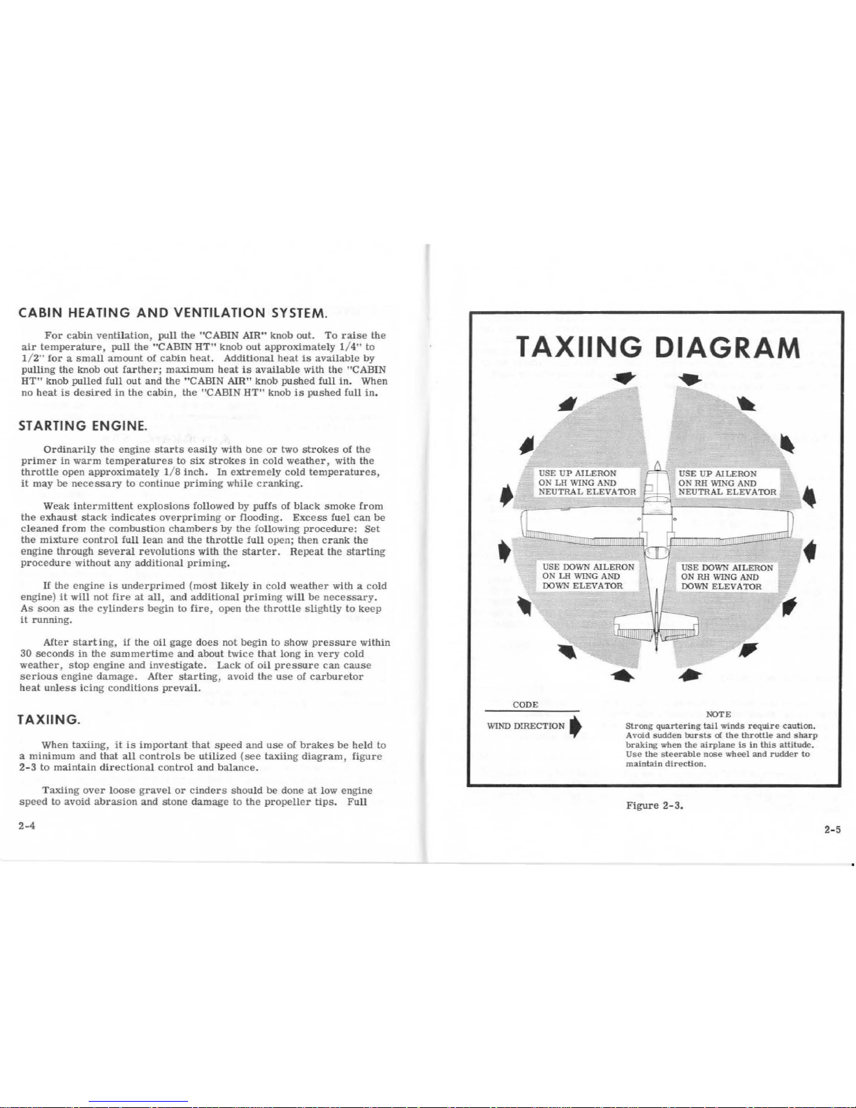
TAXIING
.
When
taxiing, it
is
important
that
speed
and
use
of
brakes
be
held
to
a
minimum
and
that
all
controls
be
utilized
(see
taxiing
diagram,
figure
2-3
to
maintain
directional
control
and
balance.
Taxiing over
loose
gravel
or
cinders
should
be
done
at
low
engine
speed
to
avoid
abrasion
and
stone
damage
to
the
propeller
tips.
Full
2-4
TAXIING
DIAGRAM
•
USE
UP
AILERON
USE
UP
AILERON
ON
LH WING
AND
.KEUTRAL
ELEVATOR
ON
RH
WING
AND
NEUTRAL
ELEV A TOR
.
CODE
WIND
D!RECTION
t
NOTE
Strong
quartering
tail
winds
require
caution.
Avoid
sudden
bursts
of
the
throttle
and
sharp
braking
when
the
airplane
is
in
this
attitude.
Use
the
steerab
l e
nose
wheel
and
rudder
to
maintain
direction.
Figure
2-3.
2-5
throttle
run-ups
over
loose
gravel
are
especially
harmful
to
propeller
tips.
When
take-offs
must
be
made
over a gravel
surface,
it
is
very
im-
portant
that
the
throttle
be
advanced
slowly.
This
allows
the
airplane
to
start
rolling
before
high
RPM
is
developed,
and
the
gravel
will
be
blown
back
of
the
propeller
rather
than
pulled
into
it.
Wben unavoidable
small
dents
appear
in
the
propeller
blades, they
should
be
immediately
cor-
rected
as
described
in
Section 4 under
propeller
care.
BEFORE
TAKE-OFF.
WARM
UP.
Since
the
engine
is
closely
cowled
for
efficient in-fli
ght
engine
cool-
ing
,
precautions
should
be
taken
to
avoid
overheating
during
prolonged
engine
operation
on
the
ground
.
MAGNETO
CHECK.
The
magneto
check
should
be
made
at
1600
RPM
as
follows: Move
the
ignition
switch
first
to
"R"
position,
and
note
RPM.
Next move
the
switch
back
to
"BOTH"
position
to
clear
the
other
set
of
plugs. Then
move
the
switch
to
the
"L"
position
and
note
RPM. The
difference
be-
tween
the
two
magnetos
operated
indi.vidually
should
not
be
more
than
75
RPM.
HIGH RPM MAGNETO CHECKS.
If
there
is
a doubt
concerning
the
operation
of
the
ignition
system
,
RPM
checks
at
higher
engine
speeds
will
usually
confirm
whether a de-
ficiency
exists.
If
a full
thro~le
run-up
is
necessary
the engine should
run
smoothly
and
turn
approximately
2230
to
2330
RPM
with the
car-
buretor
heat
off.
An
absence
of
RPM
drop
may
be
an
indication
of
faulty grounding
of
one
side
of
the
ignition
system
or
should
be
cause
for
suspicion
that
the
magneto
timing
has
been
"bumped-up"
and
is
set
in
advance
of
the
set-
ting specified
.
2-6
TAKE-OFF.
POWER CHECK.
Since the
use
of
full
throttle is
not
recommended
in
the
static
run-up,
it
is
important
to
check
full-throttle
engine
operation
early
in
the
take-off
run.
Any sig
ns
of rough
engine
operation
or
sluggish
engine
acceleration
is
good
cause
for
discontinuing
the
take-off.
If
this occurs,
you
are
j
ustifi
ed
in
ma.king a thorough
full-throttle, static
run-up
before
another
take-off
is
attempted.
Prior
to
take-off
from
fields
above
5000
ft.
elevation, the
mixture
should
be leaned
to give
maximum
RPM
in
a
full-throttle, static
run
-up.
WING
FLAP
SETTINGS
.
Normal
and
obstacle
clearance
take-offs
are
performed
with
wing
flaps up.
The
use
of 10 °
flaps
will
shorten
the
ground
run
approximately
10%,
but
this
advantage
is lost
in
the
climb
to
a 50-foot
obstacle.
There-
fore
the use
of
10°
flap
is
reserved
for
minimum
ground
runs
or
for
take-
off
from
soft
or
rough
fields
with
no
obstacles
ahead
.
If
10° of
flaps
are
used
in
ground
runs
,
it
is
preferable
to
leave
them
extended
rath
er
than
retract
them
in
the
climb
to
the
obstacle.
The
ex-
ception
to
this
rule
would
be
in
a high
altitude
take-off
in
hot
weather
where
climb
would
be
marginal
with
flaps
10° (1
st
notch).
Flap
deflections
of
30 °
to 40°
are
not
recommended
at
any
time
for
take-off.
PERFORMANCE CHARTS.
Consult
the
take-off
chart
in
Section
5,
for
take-off
distances
under
various
gross
weight,
altitude,
and
headwind
conditions.
CROSSWIND
TAKE-OFFS.
Take-offs
into
strong
crosswinds
normally
are
performed
with
the
minimum
flap
setting
necessary
for
the
field
length,
to
minimize
the
drift
angle
immediately after
take-off.
The
airplane
is
accelerated
to
2
-7
 Loading...