

Cessna Cardinal RG 1975 Owner's Manual
~
Cessna,
-
-
~-1
"TAKE
YOUR
CES~NA
HOME
fOR
SfRVICf
AT THE
SIGN
OF
THE
CfSSNA
SHIElD'.
CESSNA
AIRCRAFT
COMPANY
~
WICHITA,
k.AN5AS
'
1
'
"
"
I
~
Cessna®
MCRE PEOP.E BUY
AND
Fl'l
CESSNA
AIRPLANES
THAN
ANY
OTHER MAKE
1975
WORLD'S
LARGEST PIIO-
OUCER
OF
GENERAL
AVIATION
AIRCRAFT
SINCE
1956
~~RG
OvVNEH'S
MANUAL
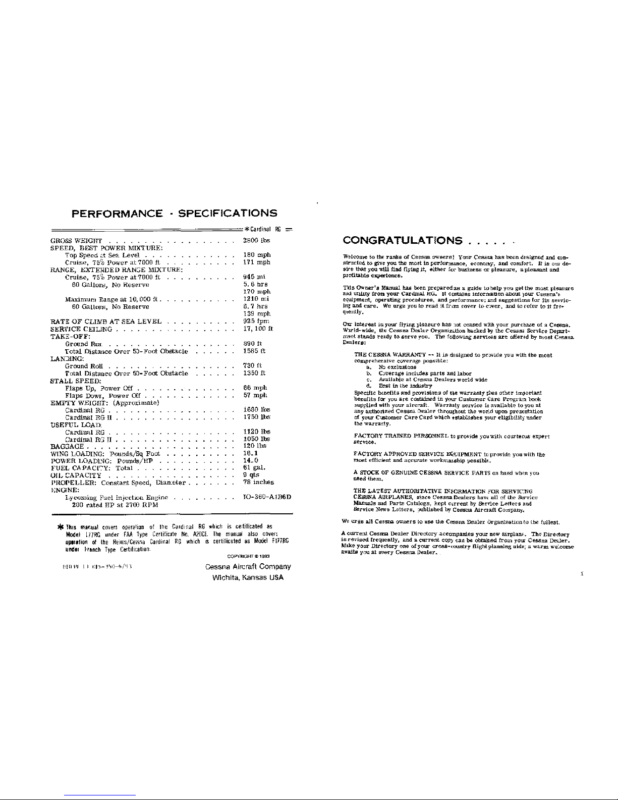
PERFORMANCE
SPECIFICATIONS
GROSS WEIGHT . . . . . . . .
SPEED,
BEST
POWER
MDITURE:
Top
Speed
4:-t
Sea
Levcl
. . .
Cruise,
75'1
Power
at
7000
ft
RANGE,
KXTENDED
RANGE MIXTURE:
Cruise,
75'1
Power
at
7000
ft
60
Gallon;,
No
Reserve
Maximum
P.ange
at
10,
000
ft
.
60
GaUors,
No
Reserve
RATE
OF
CLINB
AT
SEA
LEVEL
SER,'ICE
CEILJNG
TAK:.:<:-OFF:
Ground
Rur_
Total
Distance
OVer
5~-
Foot
Obstacle
LANJING:
Ground Roll . . . . . . . . . . .
i'otal
Distance
Over
5!)-FO<lt
Obstacle
STALL
SPEED:
Flaps
Up,
?ower
Off
• . • ,
Flaps
Dowr.,
Power
Off
. • .
EMPTY
WEIGHT:
(Approtimate)
Cardinal
RG
.
Cardinal
RG
ll
USEFUL
LOAD
Cardinal
RG .
C'arclinal
RG
II
BAGGAGE
...
, •
WING LOADING:
Pounds/Sq
Foot
POWER
LOADl~G:
Pounds/HP
FUEL
CAPACI':'Y:
Total
...
.
OIL
CAPACITY
.......
.
.I'HOPELLER:
Constant
Speed,
Dian_eter
ENGINE:
Lycoming
Fuel
Injectxm
Enbrine
200
rated
HP
at
2700
RPM
*Cardinal
RG
2800
lbs
180
mph
171
mph
945mi
5. 6
hrs
170mph
1210
mi
8.1
hrs
139
mph
925
fpm
17,100ft
890ft
1585
ft
730ft
1350
ft
66
mph
57
mph
1680
lbs
1750
lbs
1120
lbs
1050
lbs
120
lbs
16.1
14.0
61
gal.
9
qts
78
inches
I0-360-A1B6D
*11m
manual
covers
opera~ian
t.~f
lhe
CJ!d1nal
RG
which
is
certificated
as
Modfll l HRG
unde-r
FAA
Type
Gerlihcrte
No.
A20CL
The
manual
also
cove-n
i!Jitlllioo
ot
!he
Reims/Ce>Yla
Cardmal
RG
whkh
IS
mlilicaled
as
MOOel
F177RG
und11
hench
T~pe
Ce1hl1tatiorL
\!Ill
I'J i I
f:l'~-
l'>l)-h
/LJ
I
COPYliGHT e 1!!93
Cessna Aircraft Company
Wichita.
Kansas
USA
CONGRATULATIONS
.....
W~lcome
to
tb~
ranks
of
Cessna
owneraJ
Your
Cesara
has
been
dtsigzred
and
ron-
skuded
W give
you
the
most
in
performance,
econony,
and
comfort,
It
is
our
de-
sire
that
you
v.ill
find
flying
it,
either
fO!"
bu.slness
or
pleasure,
a pleaBa.nt
and
pxofitable
experience,
Tlis
Owner's
Manual haa
bwn
prepared
as
a guide
to
help
you
get
the
most
plawure
aJJd
utility
!ron
your
Card..lllal.
ftG.
U Cmrta!ns
11lfornat1on
about
~our
Cessna'~
equipment,
op~ra.ting
procedures,
and
performance;
1nd
suggestims
fQr
its
se•vic-
Jn~
and
care,
We
urge
you to
read
it
frcm
cover
to
c:Ner,
and
ta
refer
tQ
it
fN-
qvently,
01lr
iuterest
in
your
flying
pleasure
has
tot
ceasE!d wfth
your
_purchase of a
Ces>na.
W:JZld-wlde,
tt_e
Cessna
D&ler
Organizrtion
bll.cked
by
the
Cessna
Service
De(W't-
m~nt
stands
re>.dy
to
&erve
you.
The
following
serviees
are
offend
by n::cst
c~ssna
Dealers:
THE
CE.saiA
WARRANTY--
It
is
designed
to
prwide
you
with
the
most
comprehersive
coverage
possible:
a,
N:.
exdWiions
b.
C:.verage
inchdes
parts
an:llabor
c.
Available
at
Cessna
Dealen
world
wide
d,
Bsst
in
the
industry
Specific
bmE>Hts
and
provisions
-of
tke
warranty
)1us
other
important
benefits
for
you
are
conta.ined
in
your
Customer
Care
Progran
book
supplied
with
your
.airc~t.
Warra&ty
senrice
i,; availablt>
to
you
at
any
authorized
Cessna
Dealer
throughout
the
wor.d
upon
prelimtation
of
your
C1JStomer
Can
Card
which
~stabH<Ihes
~ur
eligibility
under
the
warrarty.
FACTORY
TRAINED PTSRSONNEL t·!
provide
yO\lwith
courtecus
expert
.service.
FACTORY
APPROVED
SERVICE EQUIPMENT tcpr<Wide
you
with
tile
most
effkJent
and
act'Ul'ate
workmar.ship
poasibl<'.
A STOCK OF GENUINE CESSNA SERVICE PARTS
on
hand who'n
you
need
them,
THE
LATEST
AUTHORLTATIVE INFORMATION >OR SERVIC:NG
CEBSNA AIRPLANES,
;ince
Cessna
Dealers
bav<
aU
of
the
Sa-vice
Manuals
aad
P=ts
Cahllogs,
kept
CU'rent
by
ser'l'ice
Letters
and
Berv:ice
News
Letterli,
;rublisbed
by
Cessna
Airciafi
Company.
w~
lll'ge
all
Cessna
owl'll!!rs to
use
the
Cessna
Dealer
OrganiZation
to
tbe
fullest.
A Clll'rent
Cesl:!l:lll
D<oaler
Directory
accOIDpanies
yO'I.li'
new airplaruc. TM-
Directory
is
revised
fre(pently,
and
a
current
CQP)I
can
be
obtained
from
yo.r
Cessna
De-Uer.
Mike
your
Dir~ctory
one
o1
your
cross-wuntry
flight
planning
aids; a warm
we~=me
a11a.its
you
at
rnery
Cessna
Dealer.
'
ti
/
'7111
/
-·
I .
_j..,--6~~---
/ / I ' I
_I~---=?'
--..o---==:::::__
_l__j
·-·7'1'!1AX
'::l
'=-I
~~('--)
=:;;:
~·
::~
11l'-IO"
I
C~
...
~-]
~~1a>mrom
b<lght
of
J;l~ora!t
;,
•+ ru-so
lta<
rlerressed
:>rui
o]j
""""
,~-,d""""
"'""'
pr,~•-">1'
;,.;;,tod,
*•w,r,~
~I'""
cl
;Uooralt -..
!th
,,~\.!<mal
'~
llgUs
,,,<>(l
..
d.
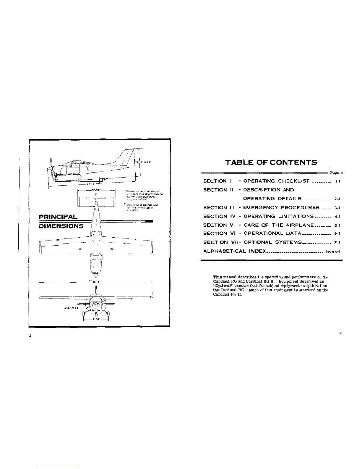
PRINCIPAL
/1\
DIMENSIONS
/
\=,
=====-•
p===?!
.··.
. -
i
~---J\]t-,
---------r==JJ
' G © :
u___--·--we
.~--·
i
~~
~~
;------------~·*
lS'-C.'
-----------']
i
...
6'-ili"
MAX.
TABLE
OF
CONTENTS
================================~~~~~======
Page
=
SECTION
I -
OPERATING
CHECKLIST
--------~
l-1
SECTION
II -
DESCRIPTION
AND
OPERATING
DETAILS-------------
2-1
SECTION
Ill -EMERGENCY
PROCEDURES-----
3-1
SECTION
IV -OPERATING
LIMITATIONS--------
4-l
SECTION
V
-
CARE
OF
THE
AIRPLA\IE
________
5-l
SECTION
VI -OPERATIONAL
DATA
______________
6-1
SECTION
VII-
OPTIONAL
SYSTEMS
______________
7-l
ALPHABETICAL
INDEX---------------------------
l,dex-1
This
manual
describes
the
;)J)eration and
performance
of
the
Cardinal
RG
and
Cardinal
RG
II.
Equ_pment des:!r-ibed
as
"Optional" denotes
that
the
subject
equipment
is
::>ptional
on
the
Cardinal
RG.
Much
of
this
equipment
is
sta:Ildard
on
th~
Cardinal
RG
II.
iii
Sution I
~~==-~--
'-=
··--
OPERATING
CHECKLIST
One
of
the
first
steJ'S
in
obtain:.ng
the
utmost
performance,
service,
and
flying
enj:;Jyment from ycrur
Cessna
is
to
familiarize
yourself
w.th
your
aircraft's
equipme1t,
systems,
and
controls.
This
can
best
be
done
by
reviewing
this
equipment
while
sitting
in
tbe
aircraft.
Those
items
whJse
function
and
operation
are
not obvious
::..re
covered
in
Section II.
Section I lists,
in
PJot's
Checklist
form,
the
steps
necessary
to
op-
er.de
your
aircraft
efficiently
and
safely.
It
is
not a
checklist
in
its
true
form
as
it
is
~onsiderably
longer,
but
it
does
cover
briefly
all
of
the
points
that
you
should
know
for a typical
fight.
A
more
convelient
plastic
en-
closed
checkl,st,
stowed
in
the
rna~
compartn,ent,
is
avllilable
for
quickly
checking
that
all
import~
procedures
have
Men
performed.
Since
vigi-
lance
for
other
traffic
is
so
important
in
crowded
termiml
areas,
it
is
important
that preoecupEtion
with
checklists
00
avoided
in
flight.
Proce-
dures
should he carefuU:r
memorized
and
performed
from
memory.
Then
the
checklist
shoold
be
quickly
scanned
to
ellS'lre
tbat
nothing
has
been
missed.
The
flight
and
operational
characteristics
of
your
ai::-craft
are
normal
in
ail
re.specl:;.
There
<.n:l
no
"un.u:mv~uUomL"
characllolristic»
ur
vper<t-
tiOllS
that
need
to
be
mastered.
All
controls
respond
in
the
normal
way
within
the
entire
range
of
operation.
All
airspeeds
mention~d
in
Sectioos
I,
II
and
III
are
indicated
airspeeds.
Corresp:mding
calibrated
ainpeed
may
be
obtaired
from
the
Airspeed
Correctioit
Table
in
Section
VI.
1-1
CD
'·
b.
'·
d.
'·
1-2
Rortf
tc
iMide
bot<
WYtr
f.)f
!iii<
mamllll
1111
<1l'Ontif...,
matorlik,
•nd
;p!!;~iolllioes
ol l,.quoMiy
"'"d
-'ci
ItaiM.
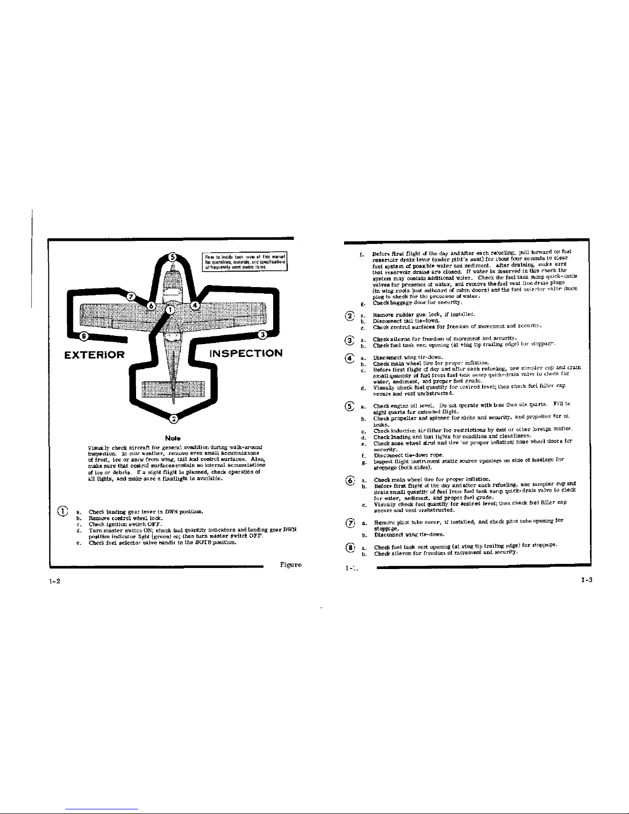
Note
Visua.ly
cheek
air(ra.ft
for
gene."lll
condition
·iuring
walk-around
lnspecl:ion.
1n
calc
weath;!r,
remove
even
small
accumuta;lons
of
frost,
ice
ax sn(w
from
wing,
tail
and
coutrol
surfaces.
Also,
make
sure
that
eont.rol
surfaces
contain
no
lnlernal
accarmlatlons
of
iee
or
debMs.
U a
night
fliglt
is
planned,
check
operation
of
allliibts,
and
make
sure a flasUigbt
is
availWle.
Checi
landing
gear
leve-r
in
DWN
position.
Remwe
control
w~ecllocl<.
Cheek
ignition
a wile
h.
OFF.
Turn
master
switc~
ON; chec.k
fuel
quantity
i;H1ieatore and
landing
gear
DWN
position
Indicator
light
(green)<£;
then
Nrn
111astet'
swltd
OFF.
Check
fuel
selecta'
valve
hancllE
in
the
BOTE
position.
Figure
@
€
€
<E
®
rz,
@
1-:.
f.
Befan
first
flight d
the
day
and
after
each
re:ueling,
pull
-forward
on
fud
~aenoir
drainlewr
{Ullder
ptld:'s
seat)
for
~bout
four
seronds
to
clear
fuel
a;;sUm
of
poss.bll'
water
am
sediment.
After
draining,
make
sure
that
rE&erv<lir
drahs
are
closed.
If
water
is
)bserved
In
tli.is
check
the
syaten
may
coo.taiD
additional
wrter.
Check
lhe
fuel
tank
rump
quick-dl:ain
valvel!i
for
presence
ilt
water,
al".i
remove
the
fuel
vent
line
drain
plugs
(jn
wir.g l'oots
just
wtboard
of
c:Jbin doo('S)
an:1
the
fuel
sel•ct<Jr
"a!v.-
drain
pl"'g
tc.
check
f!>r
tho
proscn"e
ofwate•··
g.
'·
b.
'·
'·
b.
••
b.
'·
d.
a.
b.
'·
d.
'·
f.
g.
'·
b.
'·
••
b.
'·
b.
Check
baggage
door
for
seeurity.
Remore
ruddeJ"
gus;
loci<,
if
instilled.
Disconnect
tail
tie-·iown.
Check
control
surfaces
for
freeoorn
of
mcvement
and
sccnnty.
Check
aileron
for
freedom
of
morement
and
sel'urity.
Check
fuel
tank
vel".:
open',ng {at
tiug
tip
tr..ilit;g
edge)
for
;toppagr.
Discomect
wtng
tie-down
.
Check
main
wh<:!el
tlre
for
prope:
ir.n.atlon.
Befor•
first
flight
d
day
:and aft.Er
each
refueling,
use
s::tnr•ler cup
and
train
amall
quantity
of
fllill
from
fuel
tmk
sump
qui-:k-drain vall'e
to
dwck
far
water,
sediment,
and
proper
fm:t
rrade.
Viaually
check
fuel
quantity
(or
tesired
level;
theD
check
h.ei
filler
cap
eecun
and
vent
un{bstrueted.
Check
engine
oil
le?@l. Do not
(\~<'rate
with
u-ss
thau
six
qurls.
Fi.U
l<>
eight
quarta
fer
extended
flight.
Check
p.rope.ller
and
spinner
for
nicks
and
sewrity,
and
pr·JPellcr
for
oi.
leaks.
Check
induction
air
filter
for
reatrictions
by
<tw;t
(l.f
other
:or<lign
matter.
Check
landing
and
taxi
lights
for
ccndition
and
~Ieanliness.
Ctlecknose
wheel
strut
and
tire
'or
proper
i.nflaticn;
n<;>Se
\1'heel doorB
fer
-~urity.
DtscOJme<:t tie-dOW'l
rope.
Inspect
flight
instn.ment
static
source
openings
on
side
of
Juselage
for
stopp2ge
{b<;Jth
sides).
Cheek
main
wheel
tire
for
prop"r
l.nfliill.on.
Befou
first
flight
<>1
the
day
and
after
each
rdu.,ling,
use
Ja1'11ple.r
cup
End
drain
small
quantJt:r
of
fuel
from
tuei
tank
sunp
quid:-drain
valve
t<:~
chEck
for
water,
a.edimert,
and
proper
fuel
grade.
Visua;Iy
~heck
fue-l
quantity
for
iesired
level;
then
check
f~el
filler
cap
secure
and
vent
unobstructed.
RemO're
pit<X
t\.lbe
W'ier,
if
inaU.lled, and ch<ck piicl:
tube
opening
fax
stopp<.ge.
Dlscll'lztect
wing
tl.E-dOWD.
Check
fuel
tank
vert
opening
(at
ring
tip
trailing
edge)
for
rtoppage.
Check
ail"ron
for
freedom.
af
mcrement
and
security.
1-3

BEFORE
STARTING ENGINE.
(1)
Exterinr
Preflight--
COMPLETE.
(2)
Seats,
Belts,
Sh011lder
Harnesses--
AJJUST
and
LOCK.
(3)
Fuel
Selector
Valve Handle ·-BOTH.
(4)
Radios.
Autopilot.
Electrical
Equipment --OFF.
(5}
Brakes--
TEST
~nd
SET.
(6) Cowl
Flaps --OPEN
(move
lever
out
of
locking
ht•le to
reposition).
(7}
Landin;;
Gear
Lever --DOWN.
{8)
Circuit
Breakers--
CHECK
IN.
STARTING ENGINE.
{1) MixturS!
--
IDLE
CUT-OFF.
(2)
PropeLer
--
HIGH
RPM.
(3)
Throttle
--
OPEN
1/4
INCH.
(4) :Master
SWitch--
ON.
(5)
Auxiliary
Fuel
Pump --ON.
(6)
Mixture--
ADVA~CE
to
f3
GAL/HR; then RETARD
to
IDLE
CUT-
OFF.
NOTE
If
engine
is
warm,
omit
priming
procedure
above.
(7)
Propeller
Area
--
CLEAR.
(8) IgnitiOJ Sv.·itch --START
(release
when
engine
starts).
(9)
Mixture --RICH
1:ADVANCE
smoothly
when
engine
fires).
NOrE
If
engire
floods,
turn
off
auxiliary
fuel
;rump,
place
mixture
in
idle
cut-off,
open
throttle
1/2,
and
cL"ank
engine.
When
engine
£ires,
advance
mixture
to
full
rieh
and
retard
thrvttle
promptly.
{10)
Oil
Pnssure --CHECK.
(11)
Auxiliary
Fuel
Pump--
OFF.
BEFORE
TAKE-OFF.
1-4
\I)
Parking
Brake
--SET.
(2)
Cabin
Doors--
CLOSED
and
LOCKED.
{3)
Flight
Controls --FREE
and CORRECT.
(4)
stabllator
and
Rudder
Tri:n
--TAKE-OFF.
( 5)
Fuel
Selector
,.alve
Handle --BOTH.
(6)
Throttle --1800
RPM.
a.
Magnetos--
CHECK ;RPM
drop
should not
exceed
15(1
RPM
on
either
magneto
or
50
EPM
differmtial
between
magnetos).
b.
Propeller --CYCLE
from
high
:o low RPM;
return
t{l
high
RP.N:.
e:.
Engine
Ins:ruments
and
AmmetEr --CHECK.
d.
Suction
Ga~e
--
CHECK.
(7)
Fligl\t
Instruments
and
Radios --SET.
(8)
Navigation
Lights,
Flashing
Beac-on,
and
Optimal
Strobe
Lights --ON
{as
r~quired}.
(9)
Throttle
Fricti::m
Lock--
ADJUST.
(10)
Flaps--
0"'
tol0°,
TAKE-OFF.
KORMAl TAKE-Off.
(1)
Wing
Flaps --0"
to
10°
{to"
preferred).
(2)
Power --MAXIMUM (full
throttle
aJtd
2700
RPM).
(3)
Mixture--
RlCH
(lean
for
field
elevation
per
f1:el
flow
placard
above
3COO
feet).
{4)
Aiuraft
Attitude--
LIFT
NOSE
WHEEL
at
65
:M:PH.
{5)
Climb
Speed--
75
to
85
MPH.
{6)
Brakes
--APPLY
momelltarily wha<
airborne.
{7)
Lan:ling
Gear --RETRACT
in
elimt
out.
(8)
Wing
FlapB
--RETRACT
(if
extended).
MAXIMUM
PERFORMANCE
TAtcE-Off.
(1}
Wi~
Flaps--
lDQ.
{2)
Brakes--
APPLY.
{3)
Power--
MAJ\.1MUM
(full
throttle
a.W.
2700 RPM).
(4)
Mixture--
RICH
(lean
for
field
elevation
per
fuel flow
placard
above
3000
feet).
(5}
Brakes--
RELEASE.
(6}
Air:!raft
Attitu:ie --LIF'l' NOSE WHEEL
at
60
MPH.
(7)
Climb
Speed
--
70
MPH
until
aU
obstacles
are
cleared.
(8)
Brakes--
APPLY
rnome:ttarily
when
airborne.
(9} Lar:ding
Gear --RETRACT
after
ol:Etacles
are
cleared.
(10) Wil'g
Flaps
--RETRACT
after
reaching
80
MPH.
1·5
,I
II
'
II
,ll
il
i
II
I
II
NOrE
Do
not
reduce
pov.er
until
landing
gear
and wing
flaps
have been
retracted.
ENROUTE CLIMB.
NORMAl
CLIMB.
(1) Air-speed
--
100 to 120
MPH.
{l)
Power--
25
INCHES Hg.
and
2500
RP.ft'::.
{3)
Mixture--
LEANED
to
13
GAL/HR.
{!)
Cowl
Flaps
--
OPEN
as
required.
MAXiMUM
PEtfORMANCE
CLIMB.
(l)
Airspeed--
95 MPH
at
sea
level
to
-91
MPH
at
10~000
feet.
(l)
Power--
MAXIMUM
(tull
throttle
and
2100
RPM).
(3)
Mixture --LEAN
per
fuel
fltJW
placard.
(4:)
Cowl
F:.aps --FU:.L
OPEN.
CRUISE.
(1)
Power --15 to 25 lNCHEB
Hg.,
2100
to
2500
RPM
(no
more
than
75%).
(:)
Mixture--
LEAN
per
Cessna
Power
Computer
or
Operationa:
Data,
Secticn
VI.
{l)
Cowl
F.lap5 --CLOSED.
LET-DOWN.
1-6
(1)
Power--
AS DESIRED.
NO'IE
Avoid
continuous
operation
Mween
1400
and
1750
RPM
with
less
than
10 inches
Hg.
(2)
Mixture--
ADJUST
for
smooth
operati~"'l.
(3)
Cowl
Flaps
--
CLOSED.
(4}
Wing
Flaps--
AS DESIRED
(O"
to
10"
btlow
150 M?H,
10"
to
30"
below 110
MPH).
(5)
Landing
Gear --AS
DESIRED
(do
not
Wend
above
140 MPH).
BEFORE
LANDING.
{1} Seat3,
Belts,
Harnesses
--
ADJUST
and
LOCK.
(2)
Fuel
Selector
Talve
Handle --BOTH-
{3}
Landing
Gear
--
EXTEND
below
140
MPH.
(4}
Mixklre --RIOI.
{5}
Propeller --HrGH
RPM.
(6)
Airspeed --SO
to
90
MPH
(flaps
UP).
(7) Wing
Flaps --AS
DESIRED (0"
to
10"'
below
15Cl
MPH,
10,
to
30°
below
111)
MPH).
(8)
Airspeed --70 to 80 MPH
{flaps
DOWN).
(9)
Btabilator
and
Rudder
Trirn
--ADJUST,
BALKED LANDING.
(1)
Power--
MAXIMUM
(full
throttle
ani
2700
RPM).
(2) Wmg
Flaps --RETRACT
to
20".
{3)
Airspe€d --75
MPH.
{4) Wing
Flaps--
RETRACT
slowly.
(5)
Cowl
Flaps--
OPEN.
NORMAL
LANDING.
(1}
Touchdown--
MAIN WHEELS
FIRST.
(2)
Landing
Roll--
LOWER
:t-JOSE
WHEEL
GENTLY.
(3)
Braking--
:MIMMUM
REQUIRED.
AFTER
LANDING.
(
1)
Wing
Flaps
--
UP.
(2)
Cow:
Flaps --OPEN.
SECURING AIRCRAFT.
(1)
Parl!ing
Brake--
SET.
(2}
Radios,
Electr1eal
Equipment
--
OFF.
.
(3)
Mixture--
IDLE
ClJT-OFF
(pulled
full
out).
(4)
Ignition
and
Master
Switches--
OFF_
(5)
Control
Lock--
INSTALL.
(6)
Fuel
Selector
Valve Handle --LEFT
or
RIGHT.
l-7

I
I
i
I
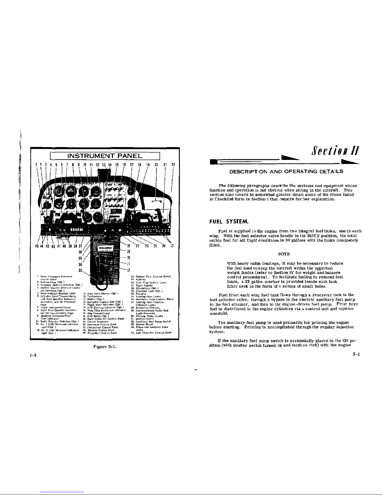
INSTRUMENT
PANEL
I
L
~c
P<~-..c•
Aler.wto
;<-A>"c"
'i«Jve
2,
!actio"
Gag.,
{0¢
J
3.
Eronomy
Mixlunlmheal<>r
iQ>t.
4,
o&ul<ec
S.,ooo
l"'u:at""
Ugk:o
em!
s~·l!<'hes
10¢
)
5. Over-1/<lilag-e
W..mi"!'
IJ;rhl
6.
Cjlind•~
<$<ad
Tl»>;><catu~
_At
Fu<>l
Qtianllt~
IM!ator,
~<m>>el•~.
aod
Ql,
Pco•.an
"""
7.
!Hglot
lnstrnmeclGrou;>
8.
Right
fi~l
QJ:.ctl'y
lod1e>.l<:>c
m<!
Oil
T<>mperalu<>
G"f><'
9.
""-m!ol,;
Pr••""<'</Fuel
;"""" lndk-';to<
lD.
'<;idla
hlt>etar
&ruehes(eyt.)
11,
.<a.
1
LOC
"""'""""
lndi."""'r
__oght
(Q?i_J
1-B
12.
)~,),
2
!.0('
lleve,..,d
tn<liU!!.o<
~ht
((Ft.)
11.
Rea•
V1ew
Mirr<n
{Opl.)
11.
T>~llffi<let"r
t>
Rl>dl~•
{Opt.)
1t.
Autoptl<>l Conlr..J
~nlt
(0;1.)
1'.
l'lighlll""<
Re«J<'<!Or[Opr,)
1!.
AUF
iS~"!;
!rdi<alor
((\It,
1
11.
W~~~&
FtQ
Switet
aod
frnti<#D~
~~.
Map
Corn]>O.rtrno..">t
ll.
ADF
flo&
(q,l.)
2!.
!light
Cohln
All
Conlrcl
K""h
2;.
CirouiC
.&re.U·~
~t.
D.:lros(.,.-
Con\:ol
l::ooi>
l\.,
O.bU!
ll..U
Om><>!
KllCb
~&.
Mixture
<:ootro
K~OO
2'.
Propel!a
Cent·<>~.
Koob
Figure
2-1.
21
~B.
-..,
Tr.m
C\mieul
Whed
211.
A,;!olray
:00.
Cffi>'l
Flap
::mrtrol
Lever
J!.
C.o:u
Llgtlu
:112.
Mtcr<>ph<mo'
!!¥1.)
~-
O:u.>1.-esy
l4;ht
(Ojt..)
$4.
Th-ll•
~0.
LandiJ>g
Ga7
Lev""
:IS.
~lator
Trim
C<lfl!rol
"'~i
;t/.
LltJ>.lJog
Ge.r
PoallW<l
I-<a\or
4;ht•
118.
Eled>-lcall»>ffoh""
11!1.
Inst=mellll..OO
lla<l!o
Thai
L!glll
Rheo.w.ts
-ro.
P>;:-l<:mg -
Ha,!l.<>
tL
JgmUm
h"tdl.
-12.
AuxUl>-r)'
-1
P><-
Swi!oh
4.1.-e<St>ut
44.
P:'l<m<!
aM
"'"il!a<Y
Mlko
- .
H.
Lei!
Cabln
Hr
Co!l!M
Koob
-
Secti011/
-
DESCRIPTON
AND
OPERATING
DETAILS
The
following
paragraphs
describe
the
systems
and
equipment
whose
function
and
operation
is
not
obvious
when
sitling
in
the
aircraft.
This
section
also
<overs
in
somewhat
greater
detail
soma
of1he
items
listed
in
Checklist
form
in
Section I that
require
fur.her
explanation.
FUEL
SYSJEM.
Fuel
is
S'Jpplied
to
the
engine
from
two
ittegral
fuel
tanks,
one
in
each
wi:ag. With the
fuel
selector
valve
handle
in
be
BOTH
position, thf-
total
us<.ble
fuel
fo:-
all
flight
conditions
is
60
gallons
with
the
tanks
completely
filled.
NOTE
With
heavy
cabin
loadings,
it
may
be
necessary
to
reduce
the
fuel
load
to
keep
the
aircraft
witbin
the
approved
weight
limits
(refer-
to
Section
IV
for
weight
and
balance
control
procedures).
To
facilitate
fueling
to
reduced
fuel
loadf., a 22 gallon
marker
is
provided.
inside
each
tank
filler
neck
in
the
form
of
a
series
of
small
holes.
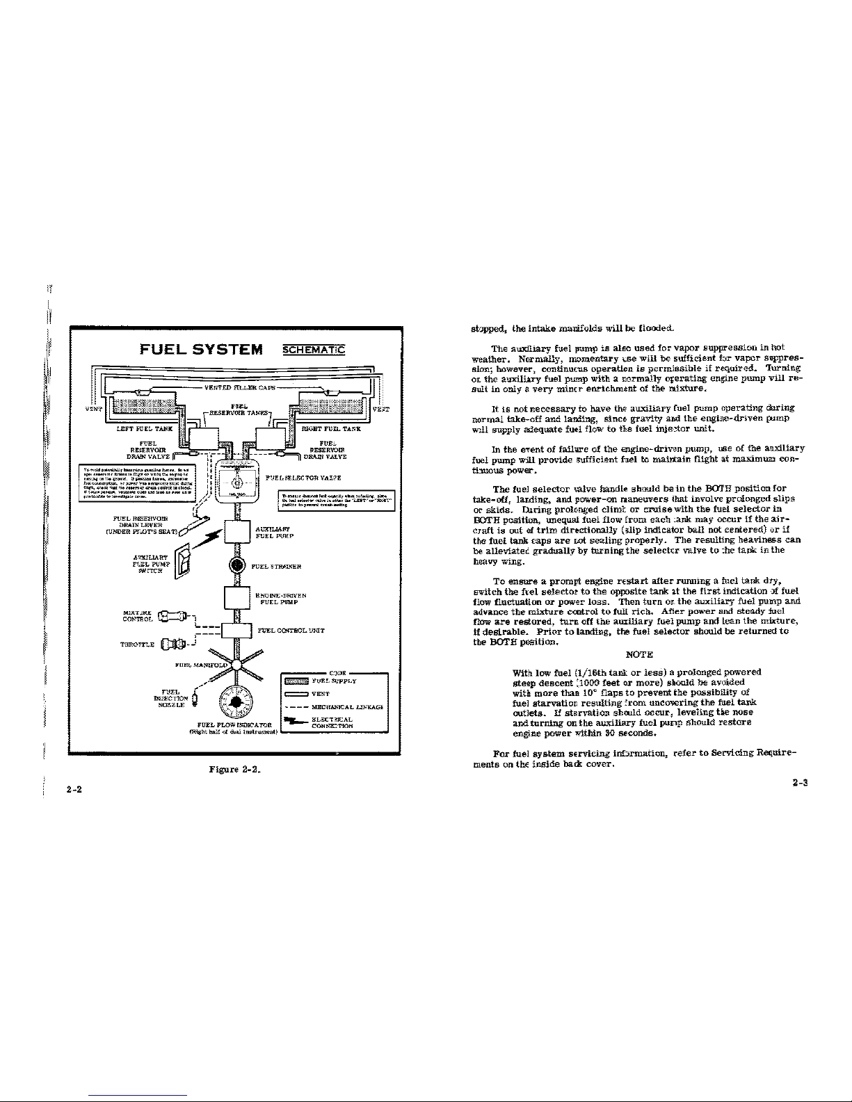
Fuel
fron
each
wing
fuel
tank
tlows throq.;h a
reserroir
tank
to
the
fud
selector
valve,
thrcugh
a bypa:;s
in
the
electric
auxiliary
fuel
pump
to
:he
fuel
strainer,
and
then
to
the
engine-driven
fuel
pump.
From
here
fuel
is
distriluted
to
the
engine
cylinders
via a control
UJiit and
injector
manifold.
The
auxiliary
fu-el
_plUllp
is
used
primarily
for
primiDg
th-e
engine
before
starting.
Priming
is
accomplished
thr:JU.gb
the
regular
injection
system.
lf
the
auxiliary
fuel
fl'Um_p
switch
is
accidentally
plactld
in
the
00
po-
sition
(with
master
switch
turned
01.
and
mixhre
rich)
with
the
engine
2-1
I
I
i
I
INSTRUMENT
PANEL
I
L
~c
P<~-..c•
Aler.wto
;<-A>"c"
'i«Jve
2,
!actio"
Gag.,
{0¢
J
3.
Eronomy
Mixlunlmheal<>r
iQ>t.
4,
o&ul<ec
S.,ooo
l"'u:at""
Ugk:o
em!
s~·l!<'hes
10¢
)
5. Over-1/<lilag-e
W..mi"!'
IJ;rhl
6.
Cjlind•~
<$<ad
Tl»>;><catu~
_At
Fu<>l
Qtianllt~
IM!ator,
~<m>>el•~.
aod
Ql,
Pco•.an
"""
7.
!Hglot
lnstrnmeclGrou;>
8.
Right
fi~l
QJ:.ctl'y
lod1e>.l<:>c
m<!
Oil
T<>mperalu<>
G"f><'
9.
""-m!ol,;
Pr••""<'</Fuel
;"""" lndk-';to<
lD.
'<;idla
hlt>etar
&ruehes(eyt.)
11,
.<a.
1
LOC
"""'""""
lndi."""'r
__oght
(Q?i_J
1-B
12.
)~,),
2
!.0('
lleve,..,d
tn<liU!!.o<
~ht
((Ft.)
11.
Rea•
V1ew
Mirr<n
{Opl.)
11.
T>~llffi<let"r
t>
Rl>dl~•
{Opt.)
1t.
Autoptl<>l Conlr..J
~nlt
(0;1.)
1'.
l'lighlll""<
Re«J<'<!Or[Opr,)
1!.
AUF
iS~"!;
!rdi<alor
((\It,
1
11.
W~~~&
FtQ
Switet
aod
frnti<#D~
~~.
Map
Corn]>O.rtrno..">t
ll.
ADF
flo&
(q,l.)
2!.
!light
Cohln
All
Conlrcl
K""h
2;.
CirouiC
.&re.U·~
~t.
D.:lros(.,.-
Con\:ol
l::ooi>
l\.,
O.bU!
ll..U
Om><>!
KllCb
~&.
Mixture
<:ootro
K~OO
2'.
Propel!a
Cent·<>~.
Koob
Figure
2-1.
21
~B.
-..,
Tr.m
C\mieul
Whed
211.
A,;!olray
:00.
Cffi>'l
Flap
::mrtrol
Lever
J!.
C.o:u
Llgtlu
:112.
Mtcr<>ph<mo'
!!¥1.)
~-
O:u.>1.-esy
l4;ht
(Ojt..)
$4.
Th-ll•
~0.
LandiJ>g
Ga7
Lev""
:IS.
~lator
Trim
C<lfl!rol
"'~i
;t/.
LltJ>.lJog
Ge.r
PoallW<l
I-<a\or
4;ht•
118.
Eled>-lcall»>ffoh""
11!1.
Inst=mellll..OO
lla<l!o
Thai
L!glll
Rheo.w.ts
-ro.
P>;:-l<:mg -
Ha,!l.<>
tL
JgmUm
h"tdl.
-12.
AuxUl>-r)'
-1
P><-
Swi!oh
4.1.-e<St>ut
44.
P:'l<m<!
aM
"'"il!a<Y
Mlko
- .
H.
Lei!
Cabln
Hr
Co!l!M
Koob
-
Secti011/
-
DESCRIPTON
AND
OPERATING
DETAILS
The
following
paragraphs
describe
the
systems
and
equipment
whose
function
and
operation
is
not
obvious
when
sitling
in
the
aircraft.
This
section
also
<overs
in
somewhat
greater
detail
soma
of1he
items
listed
in
Checklist
form
in
Section I that
require
fur.her
explanation.
FUEL
SYSJEM.
Fuel
is
S'Jpplied
to
the
engine
from
two
ittegral
fuel
tanks,
one
in
each
wi:ag. With the
fuel
selector
valve
handle
in
be
BOTH
position, thf-
total
us<.ble
fuel
fo:-
all
flight
conditions
is
60
gallons
with
the
tanks
completely
filled.
NOTE
With
heavy
cabin
loadings,
it
may
be
necessary
to
reduce
the
fuel
load
to
keep
the
aircraft
witbin
the
approved
weight
limits
(refer-
to
Section
IV
for
weight
and
balance
control
procedures).
To
facilitate
fueling
to
reduced
fuel
loadf., a 22 gallon
marker
is
provided.
inside
each
tank
filler
neck
in
the
form
of
a
series
of
small
holes.
Fuel
fron
each
wing
fuel
tank
tlows throq.;h a
reserroir
tank
to
the
fud
selector
valve,
thrcugh
a bypa:;s
in
the
electric
auxiliary
fuel
pump
to
:he
fuel
strainer,
and
then
to
the
engine-driven
fuel
pump.
From
here
fuel
is
distriluted
to
the
engine
cylinders
via a control
UJiit and
injector
manifold.
The
auxiliary
fu-el
_plUllp
is
used
primarily
for
primiDg
th-e
engine
before
starting.
Priming
is
accomplished
thr:JU.gb
the
regular
injection
system.
lf
the
auxiliary
fuel
fl'Um_p
switch
is
accidentally
plactld
in
the
00
po-
sition
(with
master
switch
turned
01.
and
mixhre
rich)
with
the
engine
2-1
I!
I.
I!!'
2-2
FUEL
SYSTEM
SCHEMATIC
T•"""''"""""'"'"'''"""-'f>oill.ruo"--,
....
"""·-
..
~.-...,.n<p=~~,..,..-~.,,.
·~"'<
~
,,.
........ ~ ,..,.
..........
'""'"~·
--"'"""_'_""''"""""""'
- ................... .,
......
,_
..
,,...c
..........
-..,.,.
....
~
......
,.
....
....,
..
~
·-·"'-"'""
..
.
FUEL
RISERVOHI
v:a:n·
FUEL
SELECTOR VAL'lE
.....................
_.;.,
.........
"""·"""
o.
t..1
~"'-'"'
«~••
'•"""•
,..~·.c-...orr
_.,
....
,
.......
"
....
......,.
DRAIN
LEVER
A/
(UNDER
ff..DT'S
SEATlV
AllX!LlAFY
A1JX!LIAHY
FtELPUMP
"""!TCH
MlJ<"rJRt
CO!o.'!ROL
THR01T"c,£
'm
INJECTION
~'~
E?«JINJ;;-IIRWEN
FUEL
PUMP
,----I
J
FUEL
C('NTBOL l-'NI'l'
'
..
I
CJDE----,
~
FUEL
:SUPPLY
c::::=l
VENT
~
---
MEC!fl,l,"JCAL
UJ>."KAGi
~EL<;;CT:ttcAL
FUEL
FLOW
INDICA TOR I
CONNE:TION
I
(l<lg!ot
hal!
o1
<hotl
in~tr-t)
Figure
2-2.
sbpped,
the
intake
manifolds
will
be
flooded.
The
auxlliary
fuel
Jl1llllP
is
also
used
for
vapor
suppression
in
hot
weather.
Nnrmally,
momentary
U>e
will
be
sufficient
br
vapor
suppres-
sion; however, continucus
operation
is
permlssible
if
required.
'Iurning
or.
the
auxiliary
fuel
pump
with a normally
orerating
engine
pump
vill
re-
sult
in
only a
very
minrr
enrichment
of
the
nrlxture.
It
is
not
necessary
to
have
the
auxiliary
fuel
pump
operating
dlring
normal
take-off
and
lanling,
since
gravity
ami
the
engine-driven
pump
Wlll
supply
adequate
fuel flow
to
the fuel
inje:tor
Wlit.
In
the
event
of
failill"e
of
the
engine-driven
pump,
lEe of the
auxiliary
fuel pump
will
provide
3ufficient fuel to
mailtain
flight at
maximum
con-
ti:ruous power-.
The
fueJ
selector
'alve
handle
should
be
in
the
BOTH
position
for
take-off,
lar.ding,
and
power-on
naneuvers
ihat
involve
prolonged
slips
or
skids.
Illring
prolonged
clim1:
or
cruise
with
the
fuel
selector
in
BOTH position, unequal
fuel
flow
from
each
:ank
may
occur
if
the
air-
craft
is
out of
trim
directionally
(;lip
indicator
ball
not
centered)
or
if
the
fuel
tank
caps
are
r.ot
sealing
properly.
The
resulting
heaviness
can
be
alleviatei
gradually
by
turning
the
selectcr
valve
to
:he
tank
in
the
heavy
wing.
To
ensure a prompt
engine
n:start
after
rmming
a fuel tank
dry,
switch
the
ft.el
selector
to
the
opposite
tank at
the
first
indication
::d
fuel
flow
fluctuation
or
power
loss.
Then
turn
or.
the
auxiliary
fuel
pump
and
advance
the
mixture
ccotrol
to
full
rich.
Afler
power
and
steady
:fuel
flow
are
restored,
turn
off
the
aw:itiary
fuel
pump
and
lean
the
mixture,
if
desirable.
Prior
to
landing, the
fuel
seleetor
should
be
returned
to
the BOTH
position.
NOTE
With low
fuel
(!/16th
tanl
or
less) a prolonged
powered
steep
descent
:1000
feet
or
more)
sllould
be
avoided
witll
more
than
10~
flaps
to
prevent
the
possibility
of
fuel
starvation
resulting
:rom
un~overing
the
fuel
tank
outlets. H starvation
shoo.ld
occur 1 leveling
tie
nose
and
turning
on
the
auxiliary
fuel
punp
should
restore
engine
power
within
30
seconds.
For
fuel
system
servicing
inf:.rmation,
refer
to
Servicing
Require-
ments
on
thE
inside
back
cover.
2-3
FUEL
TANK
SUMP
QUICK-DRAIN
VALVES.
Each
fttel
ta*
sump
is
equipped
Vlith a iuel
quick-drain
valve
to
f>.-cili-
tate
draining
and/or
examination
of:
fuel
for
conttmination
and
grade.
The
valve
extends
through
the
l<twer
surface
of
the
wing
just
out:>eard of
tiE
cabin
door. A sampler
cup
stored
in
the
aircraft
is
m~ed
to
examine
ne
fuel.
Insert
the
probe
in
the
sampler
et.tp
into
the
center
of
the
quick-
drain
valve
and
push.
Fuel
will
drain
fl'om
the
tank
S\lmp
i'lto
the
sam-
pler
cup
until
pressure
on tfl€ valw<
is
released.
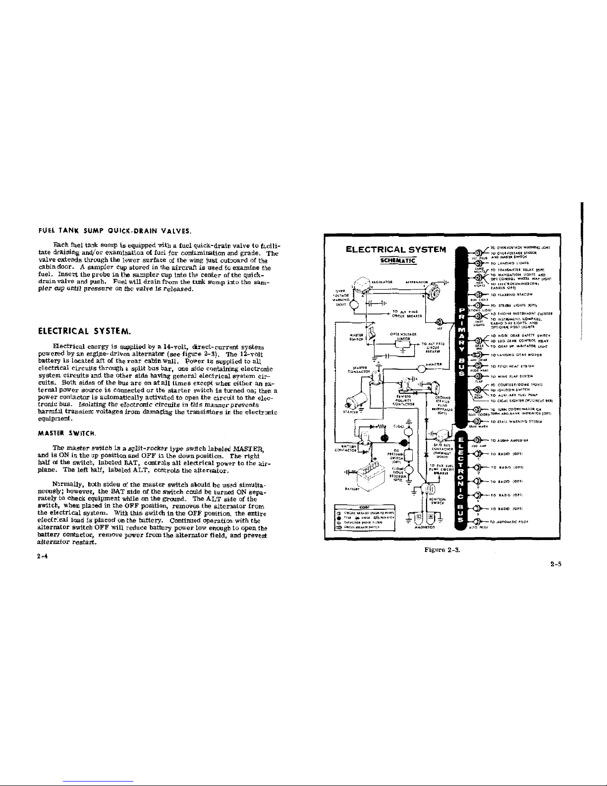
ELECTRICAL
SYSTEM.
ELectrical
energy
is
$Upplied
by a 14-volt,
direct-current
system
powered
by
an
er.gi_ne-driven
alternator
(see
figure
2.-3). The 12-v{llt
battery
is
located
aft
of
the
rear
cabin
Wall.
Power
is
supplied
to
aU
electrical
circuits
through
a
split
bus
bar,
one sJde cQfrt.aining
electronic
system
circuits
:md
the
other
side
having
general
electrical
system
ci:-
cuits.
Both
sides
of
the
bus
are
on
at
all
times
except whet:
either
an
ex-
ternal
power
source
is
connected
or
tbe
starter
switch
is
turned
on; then a
power
contactor
is
automatlcally
activated
to
open
the
circuit
to
the
elec-
tronic
bus.
Isolating
the
electronic
clt>euits
in
this
manner
prevents:
harmhl
transien::
voltages
:lrom damaging
the
transistors
ir. the
eleetr:mic
equipnent.
MASlER SWITCH.
The
master
switch
is a split-rocker
type
swftch
labele£
MASTEn,
and
is
ON
in
the
·1p
position
and
OFF
b
the
down
position.
The
right
half
o:l
the
switci:,
labeled
BAT,
contrala
all
electrical
power
to
the
air-
plane.
The
left
half,
labeled
ALT
.•
controls
the
alter.nat{lr.
N:~rmally,
b:th
sides
0::
the
mast€l"
switch
sllould
be
us~d
simulta-
neously; however, the
BAT
side
nf
the
switch
could
be
turned
ON
sepa-
rately
to
Check
equipment
while
on
the
gl"aund. The
ALT
side
of
the
switch,
when
pla~
in
the
OFF
position,
removes
the
altenator
frorn
the
electrical
system.
Witlt
this
switch
in
the
OFF
positioa
the
entire
e1ectr~ea1
load
is
placed
on
the
battery,
ContinuOO
operation
with
the
alternator
switcll
OFF
Will
reduce
battery
power
low enough
to
open
the
batter1
contactor,
remove
power
from
the
alternator
field.
and prevEnt
alternator
restart.
2-4
ELECTRICAL
SYSTEM
SCHIIUTIC
TO
..._.,
"EL"
L_l----<o~<:w
~
.......
....,,..
--~-
owa-c:~
J •
·~~
"'
MT
HlO
+--
~
~"OJ'
·-
"
<<KI>•
"'""
""""' • .,
.....
,
•
'""
ill-"'""'
"""""""o'
~~
"'"""''
"""'
"''"'
a@
'~<c.;,,
..
.,
......
,""
Figure
2-3.
''""~'
OWO-ro<T...C.. W......,t<;:J.
"""''
",...u
I"'H
$TR<l&i
i10HT!;
)mTf
~
>0
<N<>I~~
•N$Ut1W~T
CW5UO
<0
NQ;o
<><AO
V.fHY
s-.n;;~
<DO
;;tAO
CONT'tO\
O!l.d
uu.o
,..
,,...,c..,;o~
,~
)--ro
UNti
..
O
<>a•
..
OT<:)t
WtN<
nM
S<S!f
..
COtm.H/DOM<
HQ"r>
,.,N,-..o,.
swnc><
~U'-'-'""~
·~··
"""''
CUj.M
liGH!
..
(W{C10CW
0<01
~
;o
'~""'
coo•o""~'O>t
c•
~luO
...
AI<OM<N<
INN<-~T¢l(OMI
TO
SU..tl
W~ONINO
'y'""
~
ro
"""'""""'""
..
~lOUDI£>)0Pll
~
!0
U"'O
(Ofl)
U~Q
)Ofll
h-'»---to
uno
10"'
~lOUOC>IOPlJ
·-·
'
)!I
I'
I
~I
'~I
~
111
1:'
AMMETER.
The
ammeter
indicates
the
flov
of
current,
in
amperes,
from
the
alternator
to
lhe
battery
or
from
th:J
battery
to
the
aircrJt
electrical
sy~tem.
When
the
engine
is
operating
and
the
master
switch
is
ON,
the
ammeter
indicates
the
charging
rat=-
applied
to
the
battery,
In
the
event
the
alternator
is
not
functioning
or
:he
electrh:alload
exceeds
the
output
of
lbe
alternator,
the
ammeter
indi::ates
the
battery
discharge
rate.
OVER·VOLTAGE
SENSOR
AND
WARNING
LIGHT.
The
aircraft
is
equipped
with
a:t
automati<
over-voltage
protection
system
consi!?ting
of
an
over-voltage
sensor
behind the ir_strument
pwel
arui a
red
waning
light,
labeled
HIGH VOLTAGE,
near
the
ammete:-.
In
the
event
an
over-voltage
condition
occ~trs,
the
over-voltage
sen-
sor
automatically
removes
alternatar
field
current
and
shuts
down
tle
alternator.
The
red
wartling
light
will
then
turn
on,
indicating
to
the
pikt
that
the
alternator
is:
not ope>rating
and
tha
aircraft
battery
is
supply-
ing
all
electrical
pow-er.
The
over-voltage
sensor
may ~ reset
by
:urning
the
master
switch
off
and
back
on
again.
If
the
warn~
light
does
not
illuminate,
normal
alternator
cha:-ging
has
resumed;
however,
if
the
light
dres
illuminate
aga~n,_
a
malfunction
has
occurred.
and
the
flight
should
te
terminat:!d
as
soon
as
practieal.
The
warning
light
may
be
testeC
by
momertarily
turn.ng
off
the
ALT
portion
of
the
master
switch
and
leaving
the
BJ!.T
portion
turned
on.
CIRCUIT
BREAKERS
AND
FUSES.
Most
of
the
electr-ica~
circuits
in
the
aircraft
are
proJected
by
"push-
to-reset"
ciret.it
breakers
mounted
on
the
right
side
of
the
instrument
paneL
Exceptions
to
this
are
the
battery
conta:;tor
closing
(external
pow-
er}
circuit,
clcck
and
optional
flight
hour
recorder
circuits
which have
fuses:
mounted
:;ear
the
battery.
The
landing
g~ar
circuit
is
protected
by
a
push-pull
tne
circuit
b:reaker
on
lle
right
side of
the
instrument
panel,
and
the
c1gar
lighter
has a manually
r€set
type
circuit
breaker
mounted
on
t:ie
back
of
the
lighter
.wcket
When
mort
than
one
radio
is
installed,
the
radio
transmitter
relay
(which
is a part
of the
radio
installation)
is
protected
by
tEe
navigatioo
lights
circuit
b:-eaker labiOled
NAV
UGHTS.
It
is
importa~t
to
remember
2-6
tha:
any
malfunction
in
tke navigatioo
lights
system
which
causes
the
cir~t
break€r
to
open
vill
de-acth•ate
both
the
navigation
lights
ani
the
traasmitter
relay.
In
this
event,
tke navigati<m
light
switch
should
be
turned
off
to
isolate
the
eircuit;
the:t
reset
the
circuit
breaker
to
racti-
yah
the
transmitter
relay
and
permit
its
usage.
Do
not
turn
on
the
navi-
gatlon
lights
switch
until
the
malfur.ction
has
been
corrected.
LIGHTING EQUIPMENT.
EX~ERlOR.
LIGHTING.
Conventional nav-igation
lights
are
located
on
the
wine;
tips
and
bp
of
the
rudder,
landing
and
taxi
lights
are
installed
in
the
nose
cap,
at:d a
flashing
beaco1
is
mmmted
on
top
o1
the
vertical
fin.
Optional
lighting
in-
cludes
a
strobe
light
on
each
wing
tip
and
two
courtesy
li!ihts,
one
under
eaC3 wing,
just
outboard
of
the
cabb
door.
Tte
courtesy
lights
are
op-
era:::ed
by
a
switch
loeated
on
the
left
rear
doo1
post.
All
exterior
lights,
except
the
courtesy
lights,
are
cont-olled
by
rocker
type
switcbes
oa
the
left
switch
and
control
panel.
The
switches
are
ON
in
thE
up
position
and
OFF
in
the
down
position,
The
llash:ng
beacon
should
not
be
used
wh~n
flying through
douds
or
overcast;
the
ilashing
light
reflected
from
water
droplets
or
particles
in
the
atmosphere,
particularly
at
night,
can
proluce-
vertigo
and
loss
of
orientation.
The
two
bigh
intensily
strobe
li~hts
will
e.hance
anti
-collision
protec-
tior:. Howeve:-,
the
lights
should
bE
turned
off
when
taxlhg
in
the
vicinity
of
other
aircraft,
or
during
night flight
througk
clouds,
fog
or
haze.
INTERIOR LIGHTING.
Instrumert
and
conhol
panel lighting
is
provided
by flood lighting,
in-
teg:-a.Illghting.
and
optional
post
an:i eleclrolu:n1nesC£nt
Jghting.
Two
rheostat
control
knobs m the
left
svitch
and
control
pane:,
labeled
:PANEL
LKHTS
and
ENG-RADIO LIGHTS,
control
the
intensity
o:
the
instrument
and
control
patJellighting. A slide-type
switch
on
the
left
side
of
the
over-
heaj
console,
labeled
PANEL
LTS,
is
used
to
select
either
standarc
flood
2·7
~I
lighting
in
the
FLOOD
position,
optional
post
li_Jhting
in
the
POST
position,
or
a combination of
post
and
flood
lighting
in
the
BOTH
position.
Switches
a.'"ld
controls
on
the
lower
part
of
the instrurr.ent
panel
may
be
lighted
by
optional
eledroluminescent
panels
which
do
not
require
light
bulbs
for
illum:nation.
T:>
operate
t:Us
lighting.
turn
on
the
NAV
LIGHTS
switch
and
adjust
light
intensity
with
the
contra:.
knob
labeled
PANEL
LIGHTS-
Electroh1mines~nt
lighting
is
not
affected
by
the
selection
of
post
or
flood
lighting.
Instrument
and
control
panel
flood
lighting
oonsists
of
four
red
flood
lights
on
the
un:ierside
of
the
anti-glare
shield,
and a singl.e
red
flood
light
in
the
forward
part
of
the
overh:md
console.
To
use
:Iood
lighthg.
place
the
PANEL
LTS
sehdor
switcb.
in
the
FlOOD
position
and
adjust
light
intensity
'irith
the
PANEL
LIGHTS
rheostat
control
koob.
The
instrulllent
panel
may
be
eq_Upped
with
optional
post
lights
which
are :nounted
at
the
edge
of
each
instrument
or
ronl:rol
and
provide
direct
lightng.
The
Lghts
are
cr;>erated
by
placing
the
PANEL
Lt"S
selectOJ
switch
in
the
POST
positioo
and
adjurting
light
intensity
with
the
PANEL
LIGHTS
rhoostat
control
knob.
By
p:.acing
the
PANEL
LT.S
selector
switch
in
the
BOTH positia.n..
the
post
lights
can
be
used
in
comb.imtion
with
the
standard
flood
ligiling.
The
engine
instrument
cluster,
radio
equip:nent,
and
magnetic
com-
pass
have
integ.:-alligbting
and
operate
independently
of
post
or
flood light-
ing.
The
light
:ntensity
of
these
iten:s
is
controlled
by
the
ENG-RADIO
LIGETS
rheostat
control
knob.
A
cabin
dome
light
is
located
in
lhe
aft
part
of
the overhead console,
and
is
operated
by
a
switch
adjacent
io
the
light.
To
turn
the
light
on,
mOVli:
the
switcl:
to
the
right.
The
inatrunent
panel
eontrol pedestal.
may
·Je
equipped
with
an
option-
al
co.lrtesy
ligb::,
mounted
at
its
base,
which
illuminates
the
forward
cabin
floor
area.
This
light
is
controlled
by
the
courtesy
light
svttch
on
the
left
rear
door
post.
An
optional
map
light :nay be mounted on
the
bottom
of
the
pilot's
con-
trol
vheel.
The
light
illuminates
the
lower
portion
of
the
cabin
just
for-
ward
of
the
pilot
and
is
helpful when theck:ing maps
and
other
flight
data
during
night
operations.
To
operate
the
light,
first
turn
or.
the
NA
V
LrGHI'S
switch;
then
adjust
the
map
light's
intemtty
with the
knurled
diak
type
::-heostat
control
located
at
the
bcttom
of
thE
control
wlteel.
·-·
LANDING GEAR
SYSTEM.
The
retractable
tric!cle
landing
gear
is
extended and
retracted
by
hy-
draulic
actuators
powered
by
an
eledrically-driven
hydraulic
power
pack.
The
power
pack
assemblJ
is
located
aft
of
the
:-ear baggage
compartment
wan.
Mechanically-actuated wheel
well
doors
are
provided
for
the
nose
gear.
They
are
open
when
the
nose
gear
is
down
and
closed when
it
is
ret:
acted.
An
over-center
mechanical
linkage
provides
a positiYe
mechankal
up
and down lock
for
the
no~e
wheel. The
main
gear-
utilizes
hydraulic
se-
quence valve Cownloeks
and
hydraul:.c
pressur~
for
positive
uplock.
:Main
gear
uploek
pressure
.is
maintained
automatically
by
the
·power
pack
as-
sembly.
If
pressure
drlf,ls below
tlat
neeessa:y
to
retail:
uplock
pres-
sure
on
the
main
gear,
tll€
power
~ck
will
automatically
compensate.
Two
position-indicator
lights,
mounted
to
the
left
of
the
stabilator
trim
control
"'hef!I, indicate
that
the
gear
is
either
up
or
down
and
lGcked.
Both
the
gear
UP
(amber}
and
gear
DWN
{gree:t)
lights
are
the
press-to-
test
type,
inccrporating
4i.mming
stutters
for
:light
operation.
As
an
ad-
ditional
rerninier
that
the
gear
is
~racted,
a
warning
horn
sounds
inter-
mittently
wher.ever
the
tt.rottle
is
retarded
below
approxi:nately
12
inches
manifold
pressure
(master
switch
oo.)
with
the
gear
up
or
not down and
loeied.
LANDING
GEAR
LEVElL
The
gear
[ever,
mmnted
to
the
left
of
the
engine
con:rols,
has
:wo
positions
(up
f:lr
gear
up,
and
down
for
gear
down) which give a
mechan-
ical indication
of
landing
gear
position.
From
either
position,
the
l~ver
must be
pullet
out
sllghtly
to
clear
a.
detent
be:ore
it
can
be
repositioned;
operaUon of tl:e
landing
gear
system
will
not begin until
t:1e
lever
has
be-en
repositioned.
After
the
lever
has
baen repositioned, hydraulic
pressure
is
cirected
wi!hin
the
sy.Etem
to
achtate
the
ge<.r
to
the
selected
position.
Til£
gear
lever
will
remain
in
whict.ever position
bas
bee:t
selected.
During
a
normal
cycle,
the
gear
locks
up
:ll'
down and
the
position
in-
dicator
light
c:nnes
on
injicating
completion
oi
the
cycle.
Landing
gear
extension
can
be
detectee
by
illumiration
of
the
gear
DW1f
indicator
light
(green),
a.bser.ce of a
gear
warning
~orn
with
be
throttle
retarded
Mlow
approximately
12
inches
manifold
pressure,
alld
visual
inspection
of
the
m.Un
gear
position. Indication
of
gear
retracton
is
prov.ded
by
illumin-
aticn
of
the
gear
UP (amber) light. Shoold a
gear
indieabr
light
faL
to
2-9

II
illurrinate,
the
light
should
be
checlu:d
for a bumed-out
bulb
by
pressing
to
test.
A burne<i-out
bulb
can
be
replaced
in
flight
with
tt.e
bulb
fron
the
r-emaining
indicator
light.
A
safety
switch,
actu.ated
by
the
Mse
gear,
electrica.I.y
prevents
inad\<!rtent
rehaction
whenever
the
r.ose
gear
strut
is
corr.pressed
by
the
weight
of
the
ai:craft.
Also, a switch
type
eirruit
breaker
is
provickd
as a maintenance
safety
feature.
With
the
switth
pulled
rn..t,
landing
gear
operation
is
prEvented.
After
maintmance
is
campleted,
and
prior
t')
flight,
the
switch
should
bF
placed
in
the
on
poS:tion
{push~d
in).
EMERGENCY
l-AND
PUMP.
':'he
landing
gear
emezgency
hanC
pump
is
located
on
the
floor
between
the
fmnt
seats
<:nd
is
used
to
manually
extend
the
gear
in
the
event
of
hy-
draulic
pump
failure.
Whm
not
in
use,
the
pump
handle
is
retracted
and
stowEd
beneath
a.
hinged
cover
marked
with
a
placard
outlir.ing
emergency
operation
procedures.
Re:er
to
Section
ill
for
emergency
operation
oE
the
hand
pump.
CABIN
HEATING,
VENTILATING
AND
DEFROSTING
SYSTEM.
The
temperature
and volume
of
a:.rflow
into
the
cabin
can
be
regu:.ated
to
any
degree
d€sired
by
adjustment
d a
single
CABIN HEAT
knob
and
two
CABIN
AIR
knol::s.
When
r;artial
eabi:l
heat
is
desired,
ble:liiing
warm
and
cold
<dr
will
reSJJ.t
in
improved
ventilation
and
reat
distribrl:ion
thrrn;;hout
the
cabin.
I'ront
cabin
heat
and
v:ntilating
air
from
tlw
main
heat
and
ventila-
ting
system
is
nuted
throt:gh two mallifolds
located
forward
of
the
rudder
pedals
to
directionally-adjustable,
on-off
ventilaturs
on
the
front
cabb
sidewalls.
Rear
cabin
hea:
and
ail'
is
supplied
ty
ducts
from
both
fro1.t
cabin
ventilators,
one
exte:uling down
each
side
of
the
cabin
to
the
for.vard
doo~st:,
then
along
the
lo·.ver
edge
o:'
the
cabin
door
to
an
outlet
near
the
aft
eCge
of
the
{bor.
Airfbw
from
each
outlet
rnay
be
dire)ted
through
either
of
two
lowered
operlngs
by
rotating
a kncb Dn
top
of
the
Dutlet.
For
maxill'lum
rear
cabin
heating,
close
tnth
front
cabin
ventilators.
2-10
Windshield
defrost
air
is
supplied
from
the
left
cabin
manifold; t:.1ere-
fore,
the
temperature
of
the
defrosting
air
is
the
same
as
heated
cabin
air, A push-pllll
control
knob labelEd DEFROSTER
regulates
the
volume
of
air
to
the
wbdshield.
Pttll
the
kmb
out
as
necessary
for
defrosting.
Four
sepal'ately
adJustable
over1ead
ventihtor-s
supply
individual
air-;
two
are
mounted
in a console
ab:we
the
pil(lt
and
co-p-Jot,
and
two
opti(lnal
individual
ventila:ors
may
00
mounted
.n
the
rear
cabin
eeiling.
Additional
ground
and
flight
ventilation
is
available
through
an
open-
able
vent
windcw
in
each
cabin
door.
These
wi:ldows
can
'3e
opened
<.-t
speeds
up
to
HO
MPH
by
rotating
the
crank
located
below
the
window.
SHOULDER
HARNESSES.
Shoulder
larness:es
are
provided
as
standard
equipment
for
the
pilot
and
front
seat
passenger,
and
as
optional
for
tre
rear
sea:
passengers.
Seat
belts
are
standard
~ipment
for
all
passe:1gers.
E;;.ch
front
seat
harmss
is
attached
to a rear
door
post
just
above
wim:ow
line
and
is
stowed
behind
a stowage
sheath
mounte:i
above
the
cabin
door.
When stowing
the
harness,
fold
it
and
place
it
behind
the
sheath.
The
optional
rea:-
seat
shoulder
harnesses
are
attached
ad-
jace:d
to
the
lover
corners
of
the
rear
window.
Each
rea.-
seat
harn~ss
is
stowed
behh.d a stowage
sheath
located
abov~;
the
aft
side
window.
To
use
the
front
and
:-ear
seat
shoulder
harnesses,
fasten
and
adjust
the
seat
belt
fi:-st.
Remove
the
harr_ess
from
be
stowed
position,
and
lengthen
as
required
by
pulling
on
the
end
of
the
harness
aOO
the
narrow
release
strap.
Snap
the
t-arness
metal
stud
firmly
into
the
retaining
slot
adjacent
to
the
seat
belt
W.ckle.
Then
adjust
h·
length
by
pulling dov;n on
the
Tee
end
of
the
harness. A properly
adjusted
harntss
will
permit
the
occvpant
to
lean
forv;ard
enough
to
sit
completely
erect
but
is
tight
enough
to pi"event
excessive
forward
movement
and
cmtact
with
nbjects
dur:.ng
sudden
deceleration.
Also,
the
piloc
will
want
the
freedom
to
reach
all
con1rols
easily.
Releasing
and
removing
the
sho.tlder
harness
is
accomplished
by
pull-
ing
..>pward
on
:he
narrow
release
strap,
and
removing
the
harness
stud
fron
the
slot
i:t
the
seat
belt
buckle.
In
an
em?rgency,
the
shoulder
har-
ness
may
be
removed
by
releasing
the
seat
bel~
first,
and
pulling
the
har-
ness
over
the
head
by
pulling
up
on
ihe
release
strap.
2-11
INTEGRATED
SEAT
BELT
/SHOULDER
HARNESSES
WITH
INERTIA
REELS.
Optional
integrated
seat
belt/shoulder
harnesses
witi.
inertia
reels
are
ava:lable
for
the
pilot
anC
front
seat
passenger.
The
seal
belt/shoulder
harnesses
extEnd
from
inertia
reels
located
in
the
cabin
ceiling
t<J
attach
poir.ts
inboard
of
the
two
front
seats.
A
sepante
seat
belt
bali
and
buckle
is
located
ouib:)ard
of
the
seats.
Inertia
reels
allow
complete
freedom
of
bod:;
movemen:.
However,
in
the
e?ent
of
a sudden
decehration,
t!By
will
lock
up
au:ornatically
to
protect
the
occupants.
NOTE
The
inertia
reels
are
located
for
maximum
shoulder
har-
ness
comfort
and
safe
retention
11
the
seat
occuputts.
This
location
rec_uires
that
the
shoulder
harnessEes
cross
near
the top
so
t:m.t
the
right
hand
inertia
reel
serves
the
pilot
and
the
left
hand
reel
serves
the
front
passmger.
When
fastening
be
harness,
cheek
to
ensure
the
proper
harness
is
being
used.
To
uS£
the
seat
belt/shoulder
harness,
adjJSt
the
meial
Wckle
hllf
on
tlte
harness
up
far
enough
to
allov
it
to
be
drawn
across
the
lap
o1
the
occrpant
and
~
fastened
into
the
outaoard
seat
belt
bueklE.
Adjust
seat
belt
tension
by
pulling
up
::m
the
shoulder
harneas.
To
remove
the
seat
belt/shoulder
hl.rness,
rclease
the
seat
belt
bu::kle
and
allow
the
inertia
reel
to
draw
tie
harness
to
the
inboard
side
of
:he
seat.
STARTING ENGINE.
In
cold wect.her,
the
engine
com?artrnent
temperatw-e
drops
off
::-ap-
idly
following engine shutdown and the
injector
:10zzle
lines
remain
marly
full :rl fueL Cold
weather
starting
p::-ocedures
are
therefel'€
relatively
sim-
ple
with highly
predictable
results.
However,
~n
extreme~y
hot
weatler,
engbe
compartment
temperatures
irerease
rapidly
follow~ng
engine
shut-
dowtl,
and
fue!
in
the
lines
will
vaporize
and
eseape
into
the
intake
manifold.
Hot
weather
starting
procedures
depend
co:tSiderably on how socn
2-12
the
r.ext
engine
start
is
atlempted.
Within
the
f:rst
20
to
3G
minutes
alter
shutcown, the fnel manifol:i
is
adequately
primed
and
the
e-npty
injector
nozzte
lines
will
fill
before
the
engine
dies.
However,
after
approxir.Iately
30 rr.inutes, the
vaporized
fuel
in
the
manifold 'Kill
have
nearly
dissipUed
and
some
slight
"priming"
could
be
raquired
to
:'€fill
the
Mzzle
Jines
and
keep
the
engine
running
af:er
the
intt.al
start.
Starting a l:ot
engine
is
facilitated
by
advancing
the
mixture
control
promptly
to
1/3
open
when
the
engir.e
fires,
ar.d
then
smcothly
to
full
rich
as
pqwer
developes.
Should
the
engine
tend
to
die
after
starting,
turn
on
awdliary
fuel
pump
temporarily
anc.
adjust
throttle
as
necessary
to
~eep
the
ergine
running.
Weak
inter:nittent
firing
follow&
by
puffs
a:
black
smoke
from
the
exha·1st
stack
indicate
ove:--priming
or
flooding,
In
this
event,
turn
off
the
auxiliary
fuel pump, open
the
throttle
from
J2
to
full open
and
con-
throe
cranking
vith
the
mixture
full lean, When
the
engine
fires,
smoothly
adva.1.ce
the
mb:ture
control
to
full
rich
and
retard
the
thrdtle
to
desired
idle
speed.
lf
the
engine
is
under:;::rimed {moat
likely
in
cold
weather
with
a cold
engir.e)
it
will
IDt
fire
at
all,
and add..tional
priningwill
bt
necessary.
After
starting,
if
the
oil pressur:'!
gage
does
not
begin
to
show
pres-
sure
within
30
seconds
in
llie
summertime
and
about
twice
that
long in
very
cold
weath:'!r,
stop
the engine and
investigate.
Lack
af
oil
pressure
can cause serio.u>
engine
Carnage.
NOTE
Additiooal
details
concer-ning
cold
weatlter
starting
and
operation
may
be
found unde.:- COLD WEATHER
OPER-
ATION
paragraphs
in
this
section.
TAXIING.
When
taxi
ins
it
is
impor-tant
that
speed
and
use
of
brakes
be
held
::a
a
mid
mum
and
that
all
cortrols
be
ut.lized
{see
taxiing
diagram,
figu:-e
2-4)
to
maintaindirectiona.
control
and
balance.
Taxiing
over
loose
1-13
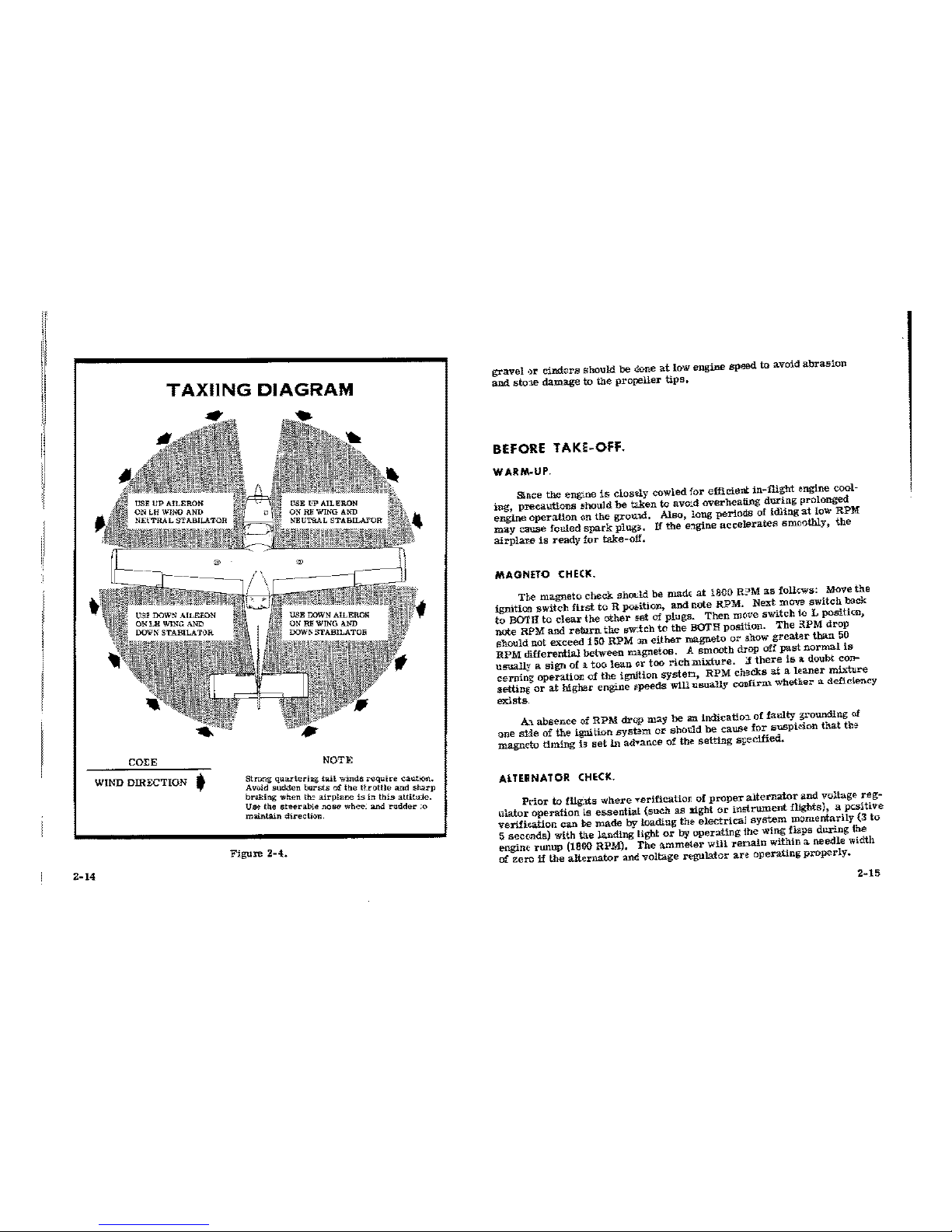
I
II
1!
TAXIING
DIAGRAM
COI:E
WIND DIRECTION '
2-14
NOTE
Stnmg
quar-lerillg
tail
winds
requir~
caution.
A vWd
sudden
bursts
oi
the
ttt"Ottle
and
sharp
br<.king
when
tiE
airplane
is
in
this
attitule.
U~
the
steerab!e
nose
whee.
and
raddttr
;o
miiintain
direction.
Figure
2-4.
gravel
•)r
cinders
should
be
done
at
tow
engine
speed
to
avoid
abrasion
and
sto:1e
damage
to
the
propeller
tips.
BEFORE TAKE-OFF.
WARM-UP.
Since
the
eng..ne
is
closely
cow
led
for
efficient
in-flight
engine cool-
ing,
precautions
!lhould
be
W!:en
to
avo:d
overheating
during
prolonged
engine
operation
on
the
grou."\d.
Also,
long
periods
of
idling
at
low RPM
may
cause
fouled
spark
plug3.
If
the
e:lgine
accelerates
smoothly,
the
airplar..e
is
ready
for
take-off.
MAGNETO
CHECK.
The
magneto
check
shrn
..
.ld
be
madE
at
1800
R?M
as
follcws:
Move
the
ignition
switch
first
to
R p06i.tion,
and
note
RPM.
Next
move
switch
back
to
BOTH
to
clear
the
other
set
of
plugs.
Then
mc•ve
switch
to L
positicc,
note
RPM
and
return
the
sw~teh
to
the
BOTH
position.
The
:tPM
drop
should
not
exceed
150
RPM
::m
either
magneto
or
show
greater
than
50
RPM
differential
between
magnetos. A smooth
drop
off
past
normal
is
usually
a
sign
of
a
too
lean
or
too
rich
mixture.
;I
there
is
a doubt
con-
cerning
operatior.
of
the
ignition
systen,
RPM
checks
at
a
leaner
mixture
setting
or
at
higher
engine
~peeds
will
usually
cODfi.rn<
whether
a deficiency
exists
A-1.
absence
of
RPM
drop
may
be
an
indicatio:l of
faulty
srounding
of
one
siie
-of
the
ignition
sy.sbm
or
shocl.d
be
cause
for
suspicion
that
the
magneto
timing
13
set
in
advance
of
the
setting
sr;ecified.
ALTEIINATOR
CHECK.
Prlor
to fllg.tts
where
verificatim:
of
proper
alternator
and
voltage
reg-
ulator
ope-ration ls
essential
{such
as
Aight
or
instrument
flights), a
pcsitive
verifieation
can
be
made
by
loading
the
electrical
system
momentarily
(3
to
5 secc.nds) with
th.e
landing
light
or
by
operating
ihe
wing
flaps
during
the
engine
runup
(1800 RPM). The
ammeter
will
renain
within a
needle
width
of
zero
if
the
alternator
and
voltage
regulator
are
operating
properly.
2-15
 Loading...