

Cessna C172S Nav III Training Manual
C172S Nav III!
Training Manual
Crosswinds Aviation
1st Edition!

Aircraft Systems 3 .....................................................................................................................
Engine 3 ..............................................................................................................................................................................................................
Oil 3 .....................................................................................................................................................................................................................
Propeller 3 ..........................................................................................................................................................................................................
Landing Gear 4 ..................................................................................................................................................................................................
Brakes 4 ..............................................................................................................................................................................................................
Flaps 4 ................................................................................................................................................................................................................
Pitot static system and instruments. 4 ..............................................................................................................................................................
Stall warning horn. 4 .........................................................................................................................................................................................
Fuel System. 5 .....................................................................................................................................................................................................
Electrical System. 6 ............................................................................................................................................................................................
Ignition System. 7 ..............................................................................................................................................................................................
G1000 System (and other avionics). 7 .............................................................................................................................................................
Performance, Weight & Balance 10 ..........................................................................................
Cessna 172s V speeds. 10 ....................................................................................................................................................................................
Weight and Balance. 10 .....................................................................................................................................................................................
C172S Procedures guide 11 ........................................................................................................
C172s Standard operaton procedures (SOP’s). 11 .............................................................................................................................................
Take off Procedures. 13 .............................................................................................................
Normal Takeoff (Flaps 0°) 13 ...........................................................................................................................................................................
Short field Takeoff (Flaps 10°) 14 ......................................................................................................................................................................
Soft field Takeoff (Flaps 10°) 15 .........................................................................................................................................................................
Landing Procedures. 16 .............................................................................................................
VFR Landing briefing procedure. 16 .................................................................................................................................................................
Before landing checklist. 16 ...............................................................................................................................................................................
Normal Landing procedure (Flaps 20°-FULL) 17 ............................................................................................................................................
Maneuver standards: +10-5 1.3x Vso approach, touchdown within 400’ of selected point. 17 .....................................................................
Short field Landing procedure (Flaps FULL) 18 ..............................................................................................................................................
Maneuver standards: +10-5 1.3x Vso approach, touchdown within 200 feet of selected point. 18 ...............................................................
Soft field Landing procedure (Flaps FULL) 19 .................................................................................................................................................
Maneuver standards: +10-5 1.3x Vso approach, touchdown with minimum sink rate. 19 ...........................................................................
Power off 180 procedure (Flaps as required) 20 ..............................................................................................................................................
Maneuver standards: N/A 20 ...........................................................................................................................................................................
Forward slips to land 21 ....................................................................................................................................................................................
Maneuver standards: touchdown within 400 feet of selected point. 21 .........................................................................................................
Emergency Procedures. 22 .......................................................................................................
Emergency Descent 22 .......................................................................................................................................................................................
Performance Maneuvers. 22 .....................................................................................................
Steep Turns 22 ....................................................................................................................................................................................................
Slow Flight 23 .....................................................................................................................................................................................................
Power On Stalls 23 .............................................................................................................................................................................................
Power Off Stalls 24 .............................................................................................................................................................................................
Ground Reference Maneuvers. 25 ............................................................................................
Rectangular Course 25 ......................................................................................................................................................................................
Turns around a point 26 ....................................................................................................................................................................................
S-Turns 27 ..........................................................................................................................................................................................................
C172S Quiz Questions. 29.........................................................................................................

Aircraft Systems
Engine
The C172S is equipped with a Lycoming, 4-cylinder, IO-360-L2A (Fuel injected, opposed,
360 cubic inch displacement) engine rated at 180 horsepower at 2700 RPM. The engine is
direct drive (crankshaft connected directly to the propeller), horizontally opposed (pistons
oppose each other), piston driven, fuel injected and normally aspirated (no turbo or
supercharging). Engine ignition is provided through the use of engine-driven magnetos, which
are independent of the aircraft's electrical system and each other and utilize impulse coupling.
The induction system has a spring loaded alternate air door inside the cowling (behind the
filter on the left hand side) that will automatically open if the air filter becomes plugged.
"
L Lycoming IO 360"
H Horizontally Opposed 4 cylinder "
A Air Cooled"
N Normally Aspirated"
D Direct Drive
Oil
The Acceptable range for oil in the C172S is 5-8 quarts. "
Never depart with the oil indicating below 5 quarts."
Use only oil approved by the flight school, never use open oil containers and risk
contamination. The engine has a full pressure wet sump type lubrication system. Oil is drawn
from the sump through an oil suction strainer screen into the engine-driven oil pump. From
the pump, oil is routed to a bypass valve. If the oil is cold, the bypass valve allows the oil to
bypass the oil cooler and go directly from the pump to the full flow oil filter. If the oil is hot,
the bypass valve routes the oil out of the accessory housing and into a flexible hose leading to
the oil cooler on the right, rear engine baffle. Pressure oil from the cooler returns to the
accessory housing where it passes through the full flow oil filter. The filter oil then enters a
pressure relief valve which regulates engine oil pressure by allowing excessive oil to return to
the sump while the balance of the oil is circulated to various engine parts for lubrication.
Residual oil is returned to the sump by gravity flow. An oil dipstick indicates the level of oil in
the tank. The dipstick is marked for US quarts.
Propeller
The C172S is equipped with a two-bladed, fixed pitch, one piece forged aluminum alloy
propellor which is anodized to retard corrosion. The propellor is 76 inches in diameter.

Landing Gear
The C172S is equipped with fixed tricycle type landing gear. The main gear is mounted to
tubalar spring struts mounted to the fuselage below the wings. The nose wheel consists of an
air oil type strut and is steerable with linkage to the rudder pedals.
Brakes
The airplane has a single-disc, hydraulically actuated brake on each main landing gear wheel.
Each brake is connected, by a hydraulic line, to a master cylinder attached to each of the
pilot's rudder pedals. The brakes are operated by applying pressure to the top of either the left
(pilot's) or right (copilot's) set of rudder pedals, which are interconnected. When the airplane
is parked, both main wheel brakes may be set by utilizing the parking brake which is operated
by a handle under the left side of the instrument panel. To apply the parking brake, set the
brakes with the rudder pedals, pull the handle aft, and rotate it 90° down.
Flaps
The single-slot type wing flaps, are extended or retracted by positioning the wing flap switch
lever on the instrument panel to the desired flap deflection position. The switch lever is moved
up or down in a slotted panel that provides mechanical stops at the 10°, 20° and 30° positions.
To change flap setting, the flap lever is moved to the right to clear mechanical stops at the 10°
and 20° positions. A scale and pointer to the left of the flap switch indicates flap travel in
degrees. The wing flap system circuit is protected by a 10- ampere circuit breaker, labeled
FLAP, on the left side of the control panel.
Pitot static system and instruments.
The pitot-static system uses a heated total pressure (pitot) head mounted on the lower surface
of the left wing, external static ports mounted on the left side of the forward fuselage and
associated plumbing to connect the GDC 74A Air Data Computer and the conventional pitotstatic instruments to the sources. The heated pitot system uses an electrical heating element
built in the body of the pitot head. The PITOT HEAT control switch is found on the switch
panel below the lower LH corner of the PFD. The PITOT HEAT circuit breaker (10 A) is
found on the circuit breaker panel at the lower LH side of the pilot panel. A static pressure
alternate source valve (ALT STATIC AIR) is located next to the throttle control. The ALT
STATIC AIR valve provides static pressure from inside the cabin if the external static pressure
source becomes blocked. If erroneous instrument readings are suspected due to water or ice in
the pressure line going to the standard external static pressure source, the alternate static
source valve should be pulled on. Pressures within the cabin will vary with open heaters/vents
and windows.
Stall warning horn.
The airplane is equipped with a pneumatic type stall warning system consisting of an inlet in
the leading edge of the left wing, an air-operated horn near the upper left corner of the

windshield, and associated plumbing. As the airplane approaches a stall, the low pressure on
the upper surface of the wings moves forward around the leading edge of the wings. This low
pressure creates a differential pressure in the stall warning system which draws air through the
warning horn, resulting in an audible warning at 5 to 10 knots above stall in all flight
conditions.
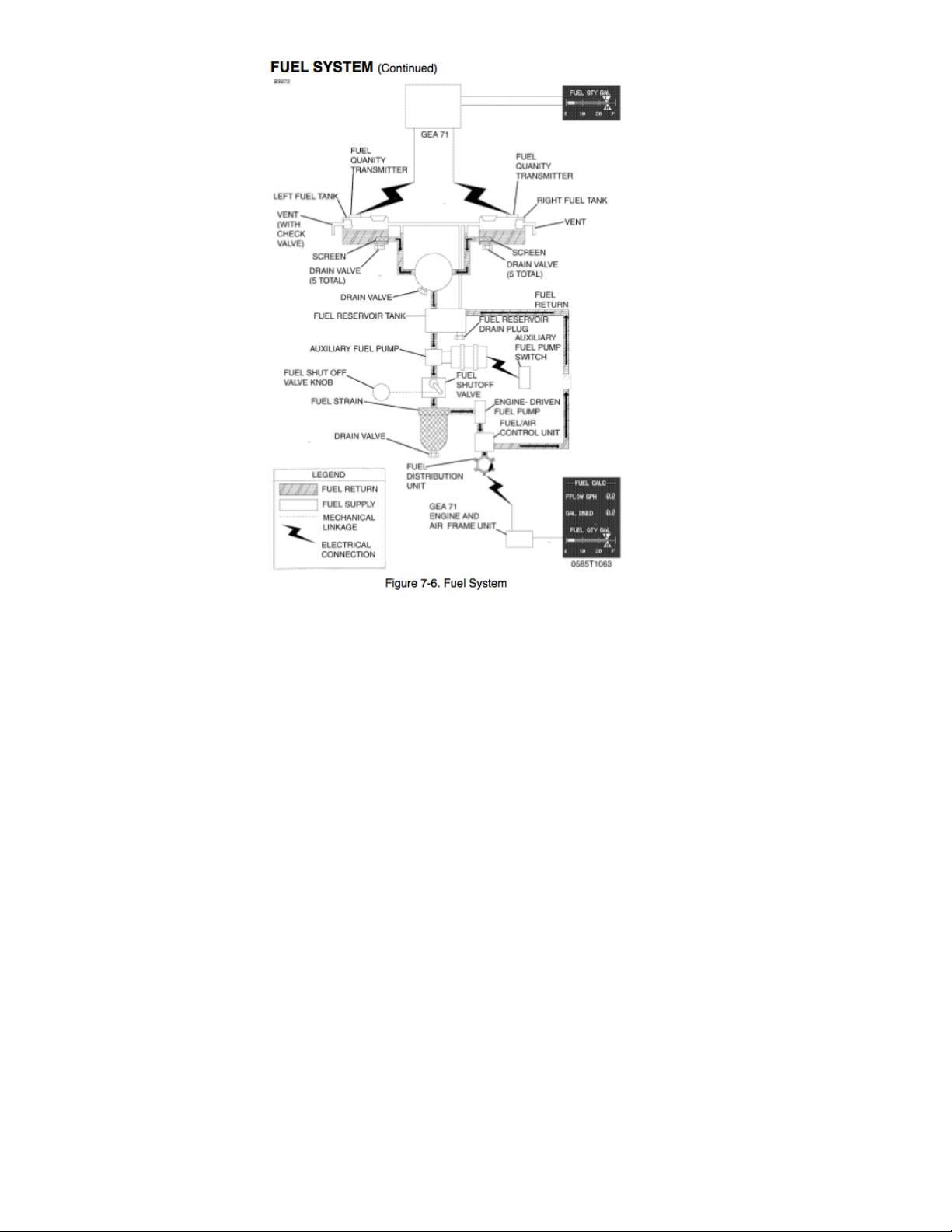
Fuel System.
Each C172S fuel tank holds 28 gallons of fuel, 26.5 is useable (56 gal total, 53 useable). The
tanks can also be fueled to the “bottom of the filler neck (“tabs”)” which is 17.5 gallons
useable per side, 35 useable gallons total. The aircraft should be serviced with blue, 100LL
fuel. The fuel should be checked for the correct fuel, contaminants, and water via the 13 fuel
sumps located on the aircraft (5 each wing, 3 under the belly going to the reservoir tank,
selector drain, and strainer).
Fuel flows by gravity from the two wing tanks to a three-position selector valve, labeled
BOTH, RIGHT and LEFT and on to the reservoir tank. From the reservoir tank fuel flows
through the auxiliary fuel pump, past the fuel shutoff valve, through the fuel strainer to an
engine driven fuel pump. From the engine-driven fuel pump, fuel is delivered to the fuel/air
control unit, where it is metered and directed to a fuel distribution valve (manifold) which
distributes it to each cylinder. Fuel flow into each cylinder is continuous, and flow rate is
determined by the amount of air passing through the fuel/air control unit. It is not necessary to
operate the auxiliary fuel pump during normal takeoff and landing, since gravity and the
engine-driven pump will supply adequate fuel flow.
The auxiliary fuel pump is used for engine priming, vapor suppression, and mechanical pump
failures.
Fuel system venting is essential to system operation. Blockage of the system will result in
decreasing fuel flow and eventual engine stoppage. The interconnected tanks vent thru the left
fuel tank vent line, which is equipped with a check valve, that protrudes from the bottom
surface of the left wing near the wing strut. Both fuel filler caps are also vented.
Instructors Note:!
Never dump sumped fuel back into
the aircraft unless your strainer has
been cleaned prior to taking a fuel
sample.
Electrical System.
The airplane is equipped with a 28-volt direct current (DC) electrical system consisting of a
belt-driven 60-ampere alternator and a 24- volt main storage battery. Individual system circuit
breakers are found on the circuit breaker panel below the pilot's control wheel. All circuit
breakers are "pullable" for electrical load management. The G1000 equipment has non-field
replaceable fuses (it is possible to blow an inline fuse and lose avionics in flight that can only
be replaced by maintenance. The storage battery is located inside the engine cowling on the
left firewall. The alternator and battery are controlled through the MASTER switch (ALT and
BAT) found near the top of the pilot's switch panel. Power is supplied to most electrical
circuits through two primary buses (ELECTRICAL BUS 1 and ELECTRICAL BUS 2), with
an Essential Bus and a crossfeed bus connected between the two primary buses to support
essential equipment. The avionics switches supply power to the avionics busses. The system is
equipped with a secondary or "standby" battery located between the firewall and the
instrument panel. The STBY BATT switch controls power to or from the standby battery. The
standby battery is available to supply power to the Essential Bus in the event that alternator
and main battery power sources have both failed.

If the alternator system fails, the MASTER switch may be set to the OFF position to preserve
Main Battery capacity for later in the flight. With the MASTER switch OFF and the STBY
BATT switch in the ARM position, the standby battery will power the Essential Bus for a
limited time. Time remaining may be estimated by monitoring Essential Bus Voltage. At 20
Volts, the standby battery has little or no capacity remaining.
The aircraft’s electrical system status is displayed to the crew via the voltmeter, ammeter, and
annunciators. Normal bus voltages with the alternator operating shall be about 28 volts. When
the voltage for either Main or Essential is at or below 24.5 volts, the numeric value and
VOLTS text turns red along with the "LOW VOLTS" annunciation. This is an indication that
the alternator is not supplying all the power that is required by the aircraft. (Indicated voltages
between 24.5 and 28 volts may occur during low engine RPM conditions).
Electric current (AMPS) indication for both the main and Standby batteries is provided at the
bottom of the EIS ENGINE or SYSTEM pages, labeled "M BATT S". Main battery current is
displayed below the "M". Standby battery current is displayed below the "S". A positive
current value (shown in white) indicates that the battery is charging. A negative current value
(shown in amber) indicates that the battery is discharging. In the event the alternator is not
functioning or the electrical load exceeds the output of the alternator, the main battery
ammeter indicates the main battery discharge rate.
In the event that Standby battery discharge is required, normal discharge should be less than 4
Amps. After engine start, with the STBY BATT switch in the ARM position, the Standby
Battery ammeter should indicate a charge showing correct charging of Standby Battery
System.
Ignition System.
The engine is provided with two independent ignition systems. The two engine driven
magnetos are independent from the power supply system, and are in operation as soon as the
propeller is turning and the ignition switch is not off. This ensures safe engine operation even
in case of an electrical power failure. When the MAGNETOS switch is rotated to the spring
loaded START position, (with the master switch in the ON position), the starter contactor is
closed and the starter, now energized, will crank the engine. When the switch is released, it
will automatically return to the BOTH position.
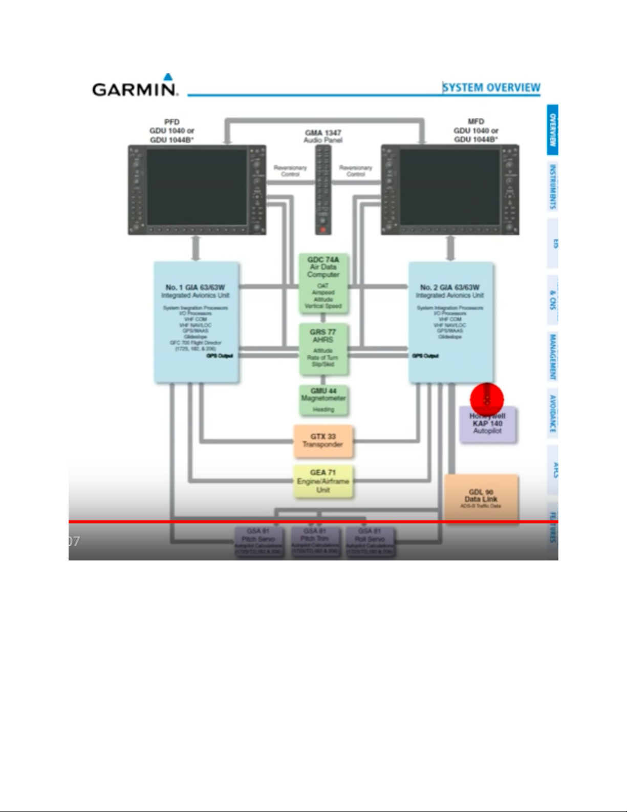
G1000 System (and other avionics).
The C172S avionics include a G1000, KAP 140 autopilot, and standby airspeed, altimeter, and
attitude indicators.
The G1000 is comprised of several main components:
Primary Flight Display (PFD, left) and Multi-Function Display (MFD, right)
Audio panel (also supplies connection between PFD & MFD for revisionary mode)
2 Avionics Units (each supplies both GPS and VHF information to G1000)

Attitude Heading Reference System (AHRS, sensors replace traditional gyros)
Magnetometer (supplies heading information to AHRS, located in left wing)
Air Data Computer (ADC, compiles info from pitot/static system and OAT)
Engine Monitor (compiles engine info and sends it to avionics unit)"
Transponder (ADS-B transponder that is operated on PFD)
XM data link (provides weather and radio data to MFD)
"
The PFD shows primary flight information in place of traditional pitot- static and gyroscopic
instruments, and also provides an HSI for navigation. A slip- skid indicator is located at the
top of the attitude indicator. Step on the “brick” instead of the “ball”. Use the reference lines
and the magenta line that appears above the heading indicator to identify a standard rate or
half-standard rate turn. Outside air temperature (OAT) displays on PFD under the airspeed
tape. Ground track can be identified on the heading indicator by a small magenta diamond
near the lubber line (only visible when ground track is different than heading). The digital
altitude and airspeed readouts are very sensitive and can cause some pilots to continuously
make corrections for insignificant deviations.
The MFD displays a large scaleable, moving map that corresponds to the airplane’s current
location. Data from other components of G1000 can be overlaid onto the MFD. The MFD is
also the principle display of engine information. Revisionary mode places basic flight info on
both PFD and MFD which allows for safe operation if a screen fails.

Performance, Weight & Balance
Cessna 172s V speeds.
Speeds listed below are in Knots Indicated Airspeed (KIAS).
Weight and Balance.
Formulas
• Weight × Arm = Moment
• Total Moment ÷ Total Weight = CG
• Max Ramp Weight – Zero Fuel Weight = Usable Fuel Weight
• Fuel Weight ÷ 6 = Fuel Gallons
• 100 LL (Blue) Fuel Weighs 6 lbs./gal.; Oil Weighs 7.5 lbs./gal.
• Unusable fuel and oil at full capacity are Included in Basic Empty Weight
Maximum Ramp Weight 2558lbs
Maximum Take off weight weight 2550lbs
Speed
KTS
Description
Airspeed indicator markings
Vso
40
Stall speed in landing configuration
Vs
48
Stall speed with zero flaps
Bottom of White Line
Vr
55
Rotation speed (start rotation)
Bottom of Green Line
Vx
62
Best angle of climb
Vy
74
Best rate of climb
VG
68
Best glide speed
Vfe
110
Maximum flap 10 degrees speed
Vfe
85
Maximum flap 20-FULL degrees speed
Top of White Line
Vno
129
Max Structural Cruising Speed
Top of Green Line
Vne
163
Never exceed speed
Red Line
Va
105
Maneuvering speed
 Loading...