

Page 1
Single Engine
MODIFICATION KIT
July 20, 2010 MK182-55-01B
TITLE
HORIZONTAL STABILIZER ABRASION BOOT INSTALLATION
EFFECTIVITY
Model Serial Numbers
182S 18280001 th
182T 18280945 and On
T182T T18208001 and On
DESCRIPTI
This modification kit provides parts and instructions for installation of abrasion boots on the leading edge of
the horizo
APPROVAL
FAA approval has been obtained on technical data in this publication that affects airplane type design.
REFERENCE
SNL06-7
WEIGHT AND
MODEL ................................ 182/T182
WEIGHTCHANGE ........................
ON
ntal stabilizer.
BALANCE INFORMATION
ru 18280944
+1.2 pounds
ARM .................................. 209.0 inch
RESULTANTMOMENT .....................
MOMENT/1000 ..........................
Original Issue: April 16, 1999 Page 1 of 6
To obtain satisfactory results, procedures specified in this publication must be accomplished in accordance with accepted methods and
prevailing government regulations. Cessna AircraftCompany cannot be responsible for the qualityof work performed in accomplishing the
requirements of this publication.
Cessna Aircraft Company, Customer Service, P.O. Box 7706, Wichita, Kansas 67277, U.S.A. (316) 517- 5800, Facsimile (316) 51 7-7271
www.cessnasupport.com
COPYRIGHT © 1999
244 inch-pounds
0.24 inch-pounds
es
Page 2
MATERIAL INFORMATION
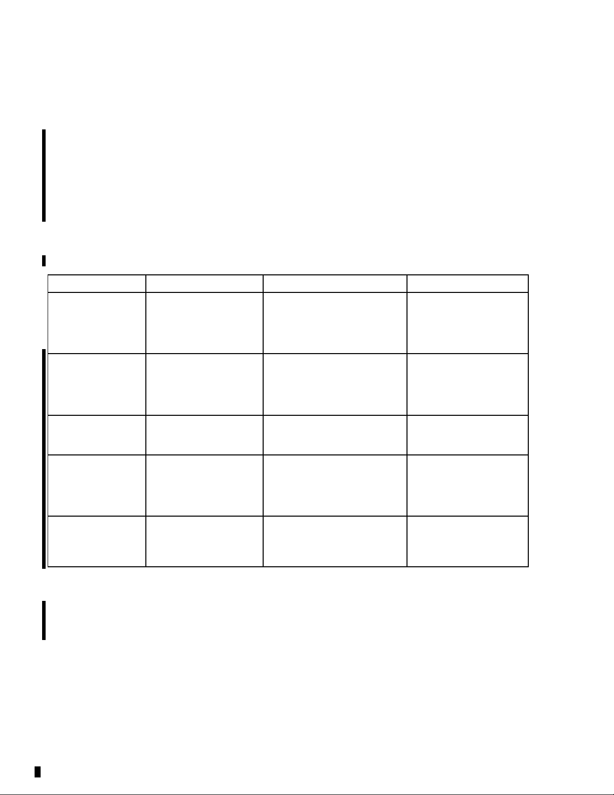
NOTE: The modification kit listed below will be necessary:
NEW P/N QUANTITY DESCRIPTION OLD P/N DISPOSITION
MK182-55-01B 1
0732042-3 1
0732042-4 1
1 Instructions
In addition to the above kit, the materials that follow, or equivalent, may be necessary:
NAME NUMBER
Alodine 1132
Marker
MPK
Masking Tape
U074093
Kit, consisting of the
following parts:
Boot, Left Stabilizer
Abrasion
Boot, Right Stabilizer
Abrasion
MANUFACTURER USE
Cessna Aircraft Company
Cessna Parts
5800 East Pawnee
PO Box 1521
Wichita, KS 6
Eastman Chemical Products
Wilcox Drive and Lincoln
Street
PO Box 1521
Kingsport, TN
Commerciall
Distribution
7218
y Available To protect boots during
1232040-5 (if
installed)
1232040-5 (if
installed)
To apply to bare metal
To remove the old
abrasion boo
application of paint
primer
Discard (if
installed)
Discard (if
installed)
ts
K000912
Scotch Brite Pad
(or 320-grit or
finer equivalent
abrasive)
ACCOMPLISHMENT INSTRUCTIONS
Corrosion
Resistant Primer
(1.5 gal kit)
Cessna Aircraft Company
Cessna Parts Distribution
5800 East Paw
PO Box 1521
Wichita, KS 67218
Commercially Available To abrade surface of
nee
To apply to bare area to
be covered by boots
horizontal stabilizer
WARNING: ELECTRICALLY GROUN D THE AIRPLANE TO PREVENT STATIC
SPARKS WHICH CAN IGNITE SOLVENT VAPORS. KEEP AIRPLANE
GROUNDED THROUGHOUT BOOT INSTALLATION.
1. Prepare the airplane for maintenance.
A. Make sure that all switches are in the OFF/NORM position.
B. Disconnect electrical power from the airplane.
(1) Disconnect the airplane battery.
(2) Disconnect external electrical power.
MK182-55-01B
Page 2 July 20, 2010
Page 3
C. Attach maintenance warning tags to the battery and external power receptacle that have "DO NOT
CONNECT ELECTRICAL POWER - MAINTENANCE IN PROGRESS" writtenonthem.
2. Make sure that the air temperature in the work area is no less than 50 °F (10 °C).
NOTE: For those airplanes that have complied with Cessna Modification Kit MK182-55-01 Original
Issue or MK182-55-01 Revision A, go to Step 3.
NOTE: For those airplanes that have not complied with Cessna Modification Kit MK182-55-01 Original
Issue or MK182-55-01 Revision A, go to Step 4.
3. Remove the 1232040-5 Left and Right Stabilizer Abrasion Boots as follows:
A. Carefully loosen one end of the 1232040-5 Left and Right Stabilizer Abrasion Boots.
B. Carefully pull the 1232040-5 Left and Right Stabilizer Abrasion Boots off of the horizontal stabilizer.
C. With Methyl n-Propyl Ketone (MPK) and a Scotch Brite pad (or equivalent), remove all signs of the
1232040-5 Left and Right Stabilizer Abrasion Boots (all of the neoprene rubber and the adhesive
that bonded it to the surface) from the surface of the horizontal stabilizer. (Refer to the Model
182/T182 Series 1997 and On Maintenance Manual, Chapter 20, General Solvents/Cleaners
- Maintenance Practices.)
D. If the leading edge of the stabilizer has no paint applied, prepare the surface as follows:
(1) Clean and prepare the surface where you will apply Alodine and corrosion resistant primer.
(Refer to the Model 182/T182 Series 1997 and On Maintenance Manual, Chapter 12, Airplane
Exterior - Cleaning/Painting.)
(2) Apply masking tape as necessary around the areas of the horizontal leading edge that are
not painted.
(3) Apply Alodine to the area.
(4) Apply a coating of corrosion resistant primer. (Refer to the Model 182/T182 Series 1997 and
On Maintenance Manual, Chapter 12, Airplane Exterior - Cleaning/Painting.)
(5) Allow the corrosion resistant primer to cure.
(6) Remove the masking tape.
4. Install the 0732042-3 Left Stabilizer Abrasion Boot and the 0732042-4 Right Stabilizer Abrasion Boot
as follows:
A. (Refer to Figure 1, Detail D.) Put masking tape on the centerline along the full length of the
0732042-3 Left Stabilizer Abrasion Boot and the 0732042-4 Right Stabilizer Abrasion Boot.
B. (Refer to Figure 1, View A-A.) With masking tape, temporarily attach the 0732042-3 Left Stabilizer
Abrasion Boot and the 0732042-4 Right Stabilizer Abrasion Boot to the horizontal stabilizer leading
edge in the correct installation position. Make sure that the centerline of the boot aligns with the
most forward edge of the horizontal stabilizer.
C. (Refer to Figure 1, Detail A, Detail B, and Detail C.) Adjust the position of the 0732042-3 Left
Stabilizer Abrasion Boot and the 0732042-4 Right Stabilizer Abrasion Boot as necessary to give
a clearance of no less than 0.10 inch between the inboard edge of the boots and the 0732614
Stabilizer Leading Edge Fairings and a clearance of no less than 0.10 inch between the outboard
edge of the boots and the 1232604 Stabilizer Tips.
NOTE: You can remove material from the 0732042-3 Left Stabilizer Abrasion Boot and the
0732042-4 Right Stabilizer Abrasion Boot as necessary to make the clearance of no less
than 0.10 inch between the inboard edge of the boots and the 0732614 Stabilizer Leading
Edge Fairings and the clearance of no less than 0.10 inch between the outboard edge of
the boots and the 1232604 Stabilizer Tips.
D. Put masking tape on the horizontal stabilizer to show the position of the edges of the 0732042-3 Left
Stabilizer Abrasion Boot and the 0732042-4 Right Stabilizer Abrasion Boot.
MK182-55-01B
July 20, 2010 Page 3
Page 4

E. Remove the 0732042-3 Left Stabilizer Abrasion Boot and the 0732042-4 Right Stabilizer Abrasion
Boot from the horizontal stabilizer.
F. As necessary, u
then clean the surface with a lint-free cloth. (Refer to the Model 182/T182 Series 1997 and On
Maintenance Manual, Chapter 20, General Solvents/Cleaners - Maintenance Practices.)
G. Remove the bac
H. Start from the inboard side of the horizontal stabilizer and attach the 0732042-3 Left Stabilizer
Abrasion Boot to the horizontal stabilizer. Remove any air that is caught between the 0732042-3 Left
Stabilizer Ab
I. Use a roller or equivalent tool to push down firmly on the surface of the 0732042-3 Left Stabilizer
Abrasion Boot.
J. Do Steps 4G thr
5. Do a paint touch-up as necessary around the 0732042-3 Left Stabilizer Abrasion Boot and the 0732042-4
Right Stabilizer Abrasion Boot.
6. Remove mainte
7. Make an entry in the airplane logbook stating that this Modification Kit has been installed.
se a Scotch Brite Pad to lightly abrade the surface of the installation area and
king from the 0732042-3 Left Stabilizer Abrasion Boot.
rasion Boot and the horizontal stabilizer.
u 4I again for the 0732042-4 Right Stabilizer Abrasion Boot.
nance warning tags and connect the airplane battery.
MK182-55-01B
Page 4 July 20, 2010
Page 5
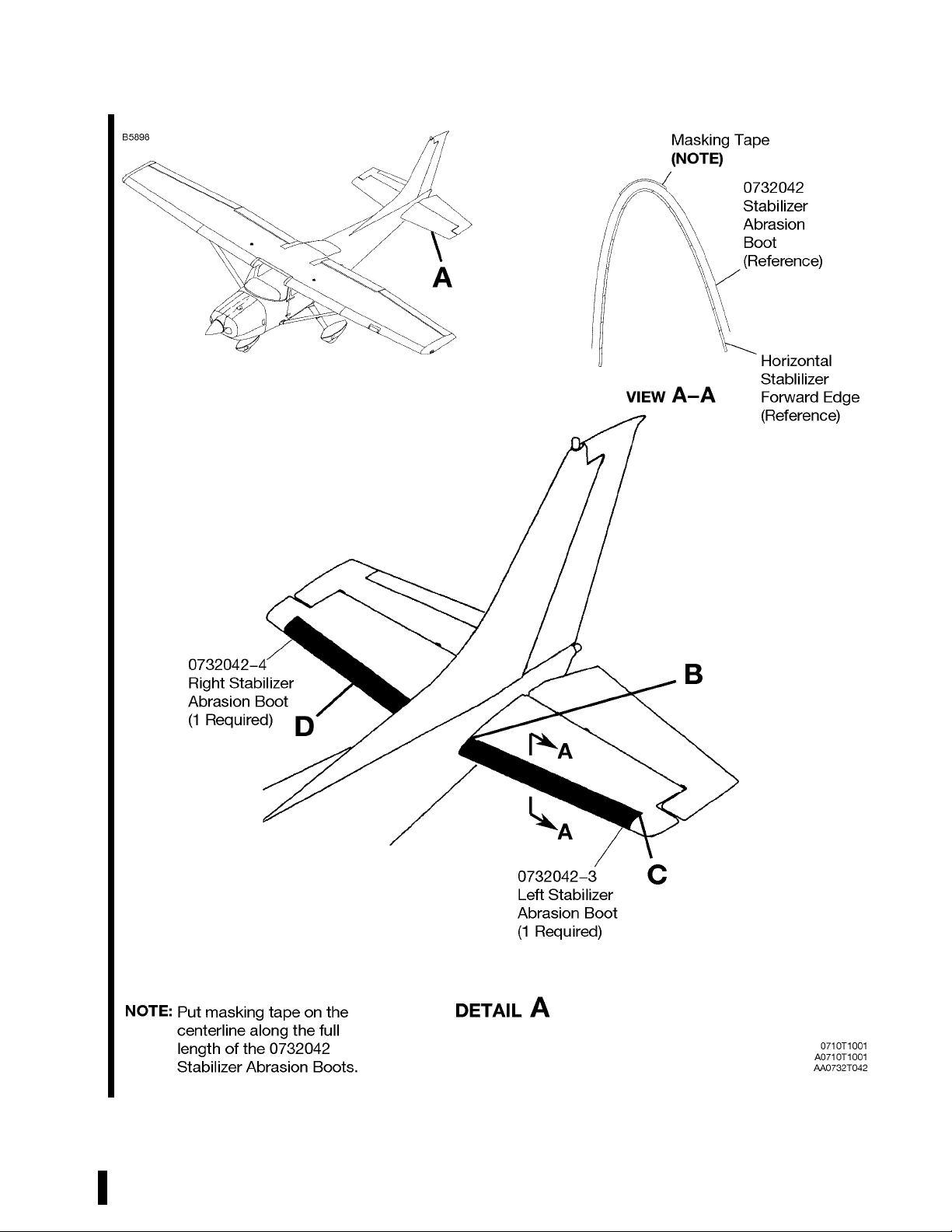
Figure 1. Horizontal Stabilizer Abrasion Boot Installation (Sheet 1)
MK182-55-01B
July 20, 2010 Page 5
Page 6
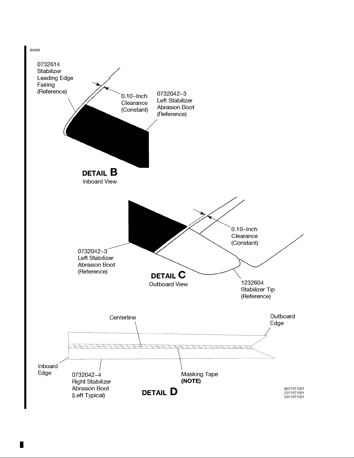
Figure 1. Horizontal Stabilizer Abrasion Boot Installation (Sheet 2)
MK182-55-01B
Page 6 July 20, 2010
 Loading...