

Page 1
Dreamfleet 2000
CESSNA MODEL 172 P
POH
THIS MANUAL IS INTENDED FOR
FLIGHT SIMULATION USE ONLY. NO
RESPONSIBILITY FOR TYPOGRAPHIC
OR OTHER ERRORS IS TAKEN.
Page 2

FOREWORD
I would like to extend my compliments and thanks to Alex
Franzen, who expended a great deal of time and talent to
produce this manual, based on the actual C-172P POH, for
the DF2000 / FSD Cessna 172P.
It is an outstanding effort! This manual is intended for use
along with the detailed documentation originally provided
with our C-172P panel, and also makes reference to certain
features of our panel.
FOREWORD
It is people such as Alex who make this hobby the great one
that it is, and we all hope you enjoy many happy hours
flying the 172, with this manual as your guide.
Happy Flying!
Louis J Betti
Executive Director - DreamFleet 2000
FLIGHT SIMULATION USE ONLY
Page 3

SECTION: | 1 | 2 | 3 | 4 | 5 | 6 | SUPP |
SECTION 1
TABLE OF CONTENTS
GENERAL INFORMATION
TOC
•Introduction
•Performance-Specifications
•Dimensions
•Descriptive Data
-Engine
-Propeller
-Fuel
-Oil
-Maximum Certificated Weight
-Standard Airplane Weight
1
1
2
3
3
3
3
3
4
4
FLIGHT SIMULATION USE ONLY
Page 4

SECTION: | 1 | 2 | 3 | 4 | 5 | 6 | SUPP |
INTRODUCTION
GENERAL INFORMATION
PAGE 1
This handbook includes the
material required to be furnished
to the pilot by CAR Part 3.
Section 1 provides basic data and
PERFORMANCE-SPECIFICATIONS
SPEED:
Maximum at sea level
Cruise, 75% power at 8000 ft
CRUISE: Recommended lean mixture with fuel allowance
for engine start, takeoff, climb and 45 minutes reserve
75% power at 8000 ft
40 gallons usable fuel
75% power at 8000 ft
50 gallons usable fuel
75% power at 8000 ft
62 gallons usable fuel
Maximum Range at 10000 ft
40 gallons usable fuel
Maximum Range at 10000 ft
50 gallons usable fuel
Maximum Range at 10000 ft
62 gallons usable fuel
RATE OF CLIMB AT SEA LEVEL
SERVICE CEILING
TAKEOFF PERFORMANCE
Ground Roll
Total Distance Over 50-ft Obstacle
LANDING PERFORMANCE (KCAS)
Ground Roll
Total Distance Over 50-ft Obstacle
STALL SPEESDS (KCAS)
Flaps Up, Power Off
Flaps Down, Power Off
MAXIMUM WEIGHT
Ramp
Takeoff or Landing
STANDARD EMPTY WEIGHT
Skyhawk
Skyhawk II
MAXIMUM USEFUL LOAD
Skyhawk
Skyhawk II
BAGGAGE ALLOWANCE
WING LOADING: Pounds/Sq Ft
POWER LOADING: Pounds/HP
FUEL CAPACITY
FLIGHT SIMULATION USE ONLY
PROPELLER: Fixed Pitch, Diameter
Standard Tanks
Long Range Tanks
Integral Tanks
123 Knots
120 Knots
440 NM
3.8 HRS
585 NM
5.0 HRS
755 NM
6.4 HRS
520 NM
5.6 HRS
680 NM
7.4 HRS
875 NM
9.4 HRS
700 FPM
13000 FT
890 FT
1625 FT
540 FT
1280 FT
51 Knots
46 Knots
2407 LBS
2400 LBS
1414 LBS
1440 LBS
993 LBS
967 LBS
120 LBS
13.8
15.0
43 GAL
54 GAL
68 GAL
75 IN
information of general interest.
NOTE:
The performance figures are
based on the indicated weights,
standard atmospheric conditions,
level, hard-surface, dry runways
and no wind. They are calculated
values derived from flight tests
conducted by the Cessna Aircraft
Company under carefully
documented conditions and will
vary with individual airplanes
and numerous factors affecting
flight performance.
Page 5
SECTION: | 1 | 2 | 3 | 4 | 5 | 6 | SUPP |
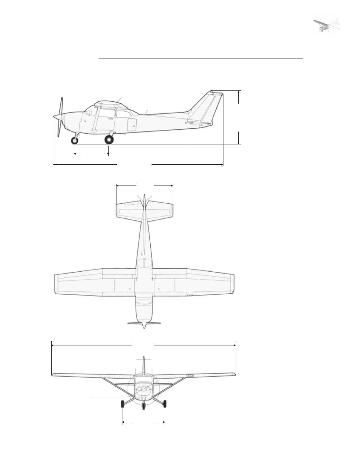
DIMENSIONS
5‘-4.15‘‘
26‘-11‘‘
11‘-4‘‘
GENERAL INFORMATION
PAGE 2
8‘-9 1/2‘‘
NOTES:
1. Wing span shown with strobe
lights installed.
2. Maximum height shown with
nose gear depressed, all tires
and nose strut properly
inflated and flashing beacon
installed
3. Proper ground clearance is
11 3/4‘‘
4. Wing area is 174 square feet
5. Minimum turning radius is
25‘-5 1/2‘‘
36‘-0‘‘
75‘‘ max
FLIGHT SIMULATION USE ONLY
8‘-4 1/2‘‘
Page 6

SECTION: | 1 | 2 | 3 | 4 | 5 | 6 | SUPP |
DESCRIPTIVE DATA
ENGINE
GENERAL INFORMATION
PAGE 3
- Number of engines: 1
- Engine Manufacturer: Avco
Lycoming
- Engine Model Number: O-320D2J
- Engine Type: Normally
PROPELLER
- Propeller Manufacturer:
McCauley Accessory Division.
- Propeller Model Number:
1C160/DTM7557
FUEL
Approved Fuel Grades:
100LL Grade Aviation Fuel (Blue)
100 (Formerly 100/130) Grade Aviation Fuel (Green)
Fuel Capacity:
Standard Tanks:
Total Capacity: 43 gallons
Total Capacity Each Tank: 21.5 gallons
Tatoal Usable: 40 gallons.
Long Range Tanks:
Total Capacity: 54 gallons
Total Capacity Each Tank: 27 gallons
Tatoal Usable: 50 gallons.
Integral Tanks:
Total Capacity: 68 gallons
Total Capacity Each Tank: 34 gallons
Tatoal Usable: 62 gallons.
aspirated, direct-drive, air-cooled,
horizontally opposed, carburetor
equipped, four-cylinder engine
with 319.8 cu.in. displacement
- Horsepower Rating and Engine
Speed: 160 rated HP at 2700 RPM
- Number of Blades: 2
- Propeller Diameter, Maximum:
75 inches, Minimum: 74 inches.
- Propeller Type: Fixed Pitch
NOTE:
Isopropyl alcohol or ethylene
glycol monomethyl ether may be
added to the fuel supply.
NOTE:
To ensure maximum fuel capacity
when refueling and minimize
cross-feeding when parked on a
sloping durface, place the fuel
selector valve in either LEFT or
RIGHT position.
OIL
Oil Grade (Specififications):
MIL-L-6082 Aviation Grade
Straight Mineral Oil: Use to
replenish supply during first 25
hours and at the forst 25-hour
oil change. Continue to use until
a total of 50 hours has
accumulated or oil consumption
has stabilized. MIL-L-22851
Ashless Dispersant Oil: This oil
must be used after first 50 hours
or oil consumption has stabilized.
FLIGHT SIMULATION USE ONLY
Page 7

SECTION: | 1 | 2 | 3 | 4 | 5 | 6 | SUPP |
MAXIMUM CERTIFICATED WEIGHT
GENERAL INFORMATION
PAGE 4
-Ramp
Normal Category: 2407 lbs
Utility Category: 2107 lbs
-Takeoff
Normal Category: 2400 lbs
Utility Category: 2100 lbs
STANDARD AIRPLANE WEIGHT
-Standard empty weight:
Skyhawk: 1414 lbs
Skyhawk II: 1440 lbs
-Maximum useful load:
Skyhawk
Normal Category: 993 lbs
Utility Category: 693 lbs
-Landing
Normal Category: 2400 lbs
Utility Category: 2100 lbs
Skyhawk II
Normal Category: 967 lbs
Utility Category: 667 lbs
NOTE:
The maximum combined weight
capacity for baggage areas 1 and
2 is 120 lbs
FLIGHT SIMULATION USE ONLY
Page 8

SECTION: | 1 | 2 | 3 | 4 | 5 | 6 | SUPP |
SECTION 2
TABLE OF CONTENTS
LIMITATIONS
TOC
•Airspeed Limitations
•Airspeed Indicator Markings
•Power Plant Limitations
•Power Plant Instrument Markings
•Weight Limits
-Normal Category
-Utility Category
•Center Of Gravity Limits
-Normal Category
-Utility category
•Maneuver Limits
-Normal Category
-Utility Category
•Flight Load Factor Limits
-Normal Category
-Utility Category
•Kinds of Operational Limits
•Fuel Limitations
1
1
2
2
3
3
3
3
3
4
4
4
5
5
FLIGHT SIMULATION USE ONLY
Page 9

SECTION: | 1 | 2 | 3 | 4 | 5 | 6 | SUPP |
AIRSPEED LIMITATIONS
LIMITATIONS
PAGE 1
Airspeed Limitations and their
operational significance are
shown in figure 2-1. Maneuvering
SPEED KCAS KIAS REMARKS
Never Exceed Speed
V
NE
Maximum Structural
V
NO
Cruising Speed
Maneuvering Speed:
V
A
2400 Pounds
2000 Pounds
1600 Pounds
FE
Maximum Flaps Extended
V
Speed:
10° Flaps
10° - 30° Flaps
speed shown apply to normal
category operations. The utility
category maneuvering speed is
Do not exceed this speed
97
91
81
84
158
in any operation
Do not exceed this speed
127
except in smooth air, and
then only with caution
Do not make full or abrupt
99
control movements above
92
this speed
82
Do not exceed this speed
110
with flaps down
85
152
123
108
102 KIAS at 2100 pounds.
Maximum Window Open
Speed
152
158
AIRSPEED INDICATOR MARKINGS
Airspeed Indicator markings and
their color code significance
MARKING KIAS VALUE SIGNIFICANCE
OR RANGE
White Arc
Green Arc
FLIGHT SIMULATION USE ONLY
Yellow Arc
Red Line
33 - 85
44 - 127
127 - 158
158
areshown in figure 2-2.
Full Flap Operating Range. Lower
limit is maximum weight V in
landing configuration. Upper limit
is maximum speed permissible with
flaps extended.
Normal Operating Range. Lower limit
is maximum weight V at most forward
C.G. with flaps retracted. Upper limit
is maximum structural cruising speed.
Operating must be conducted with
aution and only in smooth air.
Maximum speed for all operations.
Do not exceed this speed
with windows open
Figure 2-1. Airspeed Limitations
S0
S
Figure 2-2. Airspeed Indicator Makings
Page 10

SECTION: | 1 | 2 | 3 | 4 | 5 | 6 | SUPP |
POWER PLANT LIMITATIONS
LIMITATIONS
PAGE 2
-Engine Manufacturer:
Avco Lycoming.
-Engine Model Number:
O-320-D2J.
-Maximum Power:
160 BHP rating.
-Engine Operating Limits or
Takeoff and continous
Operations:
Maximum Engine Speed:
2700 RPM.
Maximum Oil Temperature:
245°F (118°C).
-Oil Pressure
Minimum: 25 psi.
Maximum: 115 psi.
-Fuel Grade: See Fuel
Limitations.
-Oil Grade (Specification):
MIL-L-6082 Aviation Grade
Streight Mineral Oil or MIL L-22851 Ashless Dispersant
Oil.
-Propeller Manufacturer:
McCauley Accessory
Division.
Propeller Model Number:
1C160/DTM7557.
-Propeller Diameter,
Maximum: 75 inches.
Minimum: 74 inches.
POWER PLANT INSTRUMENT MARKINGS
Power plant instrument markings
and their color code significance
are shown in figure 2-3
RED LINE GREEN ARC RED LINE
INSTRUMENT
MINIMUM NORMAL MAXIMUM
LIMIT OPERATING LIMIT
NOTE:
The static RPM range at full
throttle (carburetor heat off
and mixrure leaned to maximize
RPM) is 2300 tp 2420 RPM.
Tachometer:
Sea Level
5000 Feet
10000 Feet
Oil Temperature
Oil Pressure
Fuel Quantity
(Standard
Tanks)
Fuel Quantity
(Long Range
Tanks)
Fuel Quantity
(Integral
Tanks)
FLIGHT SIMULATION USE ONLY
Suction
(1.5 gal. Unusable
(2.0 gal. Unusable
(3.0 gal. Unusable
- - -
- - -
25 psi
E
Each Tank)
E
Each Tank
R
Each Tank)
- - -
Figure 2-3 Power Plant Instrument Markings
2100-2450 RPM
2100-2575 RPM
2100-2700 RPM
100°-245°F
60-90 psi
- - -
- - -
- - -
4.5 - 5.5 in. Hg
2700 RPM
245°F
115 psi
- - -
- - -
- - -
- - -
Page 11

SECTION: | 1 | 2 | 3 | 4 | 5 | 6 | SUPP |
WEIGHT LIMITS
LIMITATIONS
PAGE 3
NORMAL CATEGORY
-Maximum Ramp Weight:
2407 lbs.
-Maximum Takeoff Weight:
2400 lbs.
-Maximum Landing Weight:
2400 lbs.
-Maximum Weight in Baggage
Compartment:
Baggage Area 1 (or passenger
on child‘s seat) - Station 82
tp 108: 120lbs. See following
note.
Baggage Area 2 - Station 108
to 142: 50 lbs. See following
note.
UTILITY CATEGORY
-Maximum Ramp Weight:
2107 lbs.
-Maximum Takeoff Weight:
2100 lbs.
-Maximum Landing Weight:
2100 lbs.
-Maximum Weight in Baggage
Compartment:
In the utility category, the
baggage compartement and
rear seat must not be
occupied.
CENTER OF GRAVITY LIMITS
NORMAL CATEGORY
UTILITY CATEGORY
NOTE:
The maximum combined weight
capacity for baggage
areas 1 and 2 is 120 lbs.
-Center of Gravity Range:
Forward: 35.0 inches aft of
datum at 1950 lbs or less,
with straight line variation to
39.5 inches aft of datum at
2400 lbs.
Aft: 47.3 inches aft of datum
at all weights.
Reference datum: Lower
portion of front face of
firewall.
-Center of Gravity Range:
Forward: 35.0 inches aft of
datum at 1950 lbs or less,
with straight line variation to
36.5 inches aft of datum at
2100 lbs.
Aft: 40.5 inches aft of datum
at all weights.
Reference datum: Lower
portion of front face of firewall.
MANEUVER LIMITS
NORMAL CATEGORY
This airplane is certificated in
FLIGHT SIMULATION USE ONLY
both the normal and utility
category. The normal category is
applicable to aircraft intended
for non-aerobatic operations.
These include any maneuvers
incidental to normal flying,
stalls (except whip stalls), lazy
eights, chandelles, and turns in
which the angle of bank is not
more than 60°. Aerobatic
maneuvers, including spins,
are not approved.
Page 12

SECTION: | 1 | 2 | 3 | 4 | 5 | 6 | SUPP |
LIMITATIONS
PAGE 4
UTILITY CATEGORY
This airplane is not designed for
purely aerobatic flight. However,
in the aquisition of various
certificates such a commercial
pilot and flight instructor, certain
maneuvers are required by the
FAA. All of these maneuvers are
MANEUVER
Chandelles
Lazy Eights
Steep Turns
Spins
Stalls (except Whip Stalls)
*Abrupt use of the controls is prohibited above 99 knots
Aerobatics that may impose high
loads should not be attempted.
The important thing to bear in
mind in flight maneuveres is that
the airplane is clean in
aerodynamic design and will buils
up speed quickly with the nose
down. Proper speed control is an
essential requirement for
execution of any maneuver, and
care should always be exercised
permitted in this airplane when
operated in the utility category.
In the utility category, the
baggage compartment and rear
seat must not be occupied. No
aerobatic maneuvers are
approved except those listed
below:
RECOMMENDED ENTRY SPEED*
105 knots
105 knots
95 knots
Slow Deceleration
Slow Deceleration
to avoid excessive speed which
in turn can impose excessive
loads. In the execution of all
maneuvers, avoid abrupt use of
the controls. Intentional spins
with flaps extended are
prohibited.
FLIGHT LOAD FACTOR LIMITS
NORMAL CATEGORY
Flight Load Factors (maximum Takeoff Weight - 2400 lbs):
UTILITY CATEGORY
Flight Load Factors (maximum Takeoff Weight - 2100 lbs):
FLIGHT SIMULATION USE ONLY
*Flaps Up +3.8g, -1.52g
*Flaps Down +3.0g
*The design load factors are 150% of the
above, and in all cases, the structure meets
or exceeds design loads.
*Flaps Up +4.4g, -1.76g
*Flaps Down +3.0g
*The design load factors are 150% of the
above, and in all cases, the structure meets
or exceeds design loads.
Page 13

SECTION: | 1 | 2 | 3 | 4 | 5 | 6 | SUPP |
KINDS OF OPERATIONAL LIMITS
LIMITATIONS
PAGE 5
The airplane is equipped for day
VFR and may be equipped for
night VFR and/or IFR operations.
FAR Part 91 establishes the
minimum required
FUEL LIMITATIONS
Fuel Capacity:
Standard Tanks:
Total Capacity: 43 gallons
Total Capacity Each Tank: 21.5 gallons
Tatal Usable: 40 gallons
Long Range Tanks:
Total Capacity: 54 gallons
Total Capacity Each Tank: 27 gallons
Tatal Usable: 50 gallons
Integral Tanks:
Total Capacity: 68 gallons
Total Capacity Each Tank: 34 gallons
Tatal Usable: 62 gallons
instrumentation and equipment
for these operations. The reference to types of flight operations
on the operating limitations
placard reflects equipment
installed at the time of
Airworthiness Certificate issuance.
Flights into known icing
conditions is prohibited.
NOTE:
To ensure maximum fuel capacity
when refueling and minimize
cross-feeding when parked on a
sloping surface, place the fuel
selector valve either LEFT or
RIGHT position.
Takeoff and land with the fuel
selector valve handle in the BOTH
position
Maximum slip or skid duration
with one tank dry: 30 seconds.
With 1/4 tank or less, prolonged
imcoordinated flight is prohibited
when operating on either left or
right tank in level flight.
Fuel remaining in the tank after
the fuel quantity indicator reads
empty (red line) cannot be safely
used in flight.
FLIGHT SIMULATION USE ONLY
Page 14

SECTION: | 1 | 2 | 3 | 4 | 5 | 6 | SUPP |
SECTION 3
TABLE OF CONTENTS
EMERGENCY PROCEDURES
TOC
•Introduction
•Airspeeds for Emergency Procedures
•Engine Failures
-Engine Failure during Takeoff Run
-Engine Failure immediately after T/O
-Engine Failure during Flight
•Forced Landings
-Emergency Landing without Engine Power
-Precautionary Landing with Engine Power
-Ditching
•Fires
-During Start on Ground
-Engine Fire in Flight
-Electrical Fire in Flight
-Cabin Fire
-Wing Fire
•Landing with a Flat Main Tire
•Electrical Power Supply System Malfunctions
-Ecxessive rate of Discharge
-Low-Voltage Light illuminates
•Icing
-Inadverted Icing Encounter
-Static Source Blockage
1
1
1
1
2
2
2
3
3
4
4
4
4
5
5
5
6
6
FLIGHT SIMULATION USE ONLY
Page 15

SECTION: | 1 | 2 | 3 | 4 | 5 | 6 | SUPP |
INTRODUCTION
EMERGENCY PROCEDURES
PAGE 1
This Section provides checklists
and amplified procedures for
coping with emergencies that
might occur. Emergencies caused
by airplane or engine
malfunctions are extremely rare
if proper preflight inspections
and maintainance are practiced.
Enroute weather emergencies can
be minimized or eliminated by
careful flight planning and good
judgement when unexpected
weather is encountered. However,
should an emergency arise, the
AIRSPEEDS FOR EMERGENCY OPERATION
Engine Failure After Takeoff:
Wing Flaps Up
Wing Flaps Down
Maneuvering Speed:
2400 Lbs
2000 Lbs
1600 Lbs
Maximum Glide
Precautionary Landing With Engine Power
Landing Without Engine Power:
Wing Flaps Up
Wing Flaps Down
65 KIAS
60 KIAS
99 KIAS
92 KIAS
82 KIAS
65 KIAS
60 KIAS
65 KIAS
60 KIAS
basic guidelines described in this
section should be considered and
applied as necessary to correct
the problem. •
ENGINE FAILURES
ENGINE FAILURE DURING TAKEOFF RUN
[1] Throttle --- IDLE
[2] Brakes --- APPLY
[3] Wing Flaps --- RETRACT
[4] Mixture --- IDLE CUT-OFF
[5] Ignition Switch --- OFF
[6] Master Switch --- OFF
ENGINE FAILURE IMMEDIATELY AFTER
TAKEOFF
[1] Airspeed --- 65 KIAS (flaps up)
60 KIAS (flaps down)
[2] Mixture --- IDLE CUT-OFF
[3] Fuel Selector Valve --- OFF
FLIGHT SIMULATION USE ONLY
[4] Ignition Switch --- OF
[5] Wing Flaps --- AS REQUIRED
[6] Master Switch --- OFF
Page 16

SECTION: | 1 | 2 | 3 | 4 | 5 | 6 | SUPP |
ENGINE FAILURE DURING FLIGHT
[1] Airspeed --- 65 KIAS
[2] Carburetor Heat --- ON
[3] Fuel Selevtor Valve --- BOTH
[4] Mixture --- RICH
[5] Ignition Switch --- BOTH
[6] Primer --- IN and LOCKED
FORCED LANDINGS
EMERGENCY LANDING WITHOUT
ENGINE POWER
[1] Airspeed --- 65 KIAS (flaps up)
60 KIAS (flaps down)
[2] Mixture --- IDLE CUT-OFF
[3] Fuel Selector Valve --- OFF
[4] Igition Switch --- OFF
[5] Wing Flaps --- AS REQUIRED
(30° recommended)
[6] Master Switch --- OFF
[7] Doors --- UNLATCH PRIOR
TO TOUCHDOWN
[8] Touchdown --- SLIGHTLY TAIL LOW
[9] Brakes --- APPLY HEAVILY
EMERGENCY PROCEDURES
PAGE 2
PRECAUTIONARY LANDING WITH
ENGINE POWER
[1] Wing Flaps --- 20°
[2] Airspeed --- 60 KIAS
[3] Selected Field --- FLY OVER, noting terrain
and obstruction then retract
flaps upon reaching a safe
altitude and airspeed
[4] Avionics Power Switch
and Electrical Switches --- OFF
[5] Wing Flaps --- 30° (on final approach)
[6] Airspeed --- 60 KIAS
[7] Master Switch --- OFF
[8] Doors --- UNLATCH PRIOR
FLIGHT SIMULATION USE ONLY
[9] Touchdown --- SLIGHTLY TAIL LOW
[10] Ignition Switch --- OFF
[11] Brakes --- APPLY HEAVILY
TO TOUCHDOWN
Page 17

SECTION: | 1 | 2 | 3 | 4 | 5 | 6 | SUPP |
DITCHING
EMERGENCY PROCEDURES
PAGE 3
[1] Radio --- TRANSMIT MAYDAY on
121.5 MHz, giving location
and intentions and
SQUAWK 7700
[2] Heavy Objects) --- SECURE OR JETTISON
[3] Approach
High Winds, Heavy Seas --- INTO THE WIND
Lgt. Winds, Heavy Swells --- PARALLEL TO SWELLS
[4] Wing Flaps --- 20° - 30°
[5] Power --- ESTABLISH 300 FT/MIN
DESCENT AT 55 KIAS
[6] Cabin Doors --- UNLATCH
[7] Touchdown --- LEVEL ATTITUDE AT EST.
RATE OF DESCENT
[8] Face --- CUSHION at touchdown
with folded coat
[9] Airplane --- EVACUATE through cabin
doors.
[10] Life Vests and Raft --- INFLATE
REMEMBER:
Mayday 121.5 MHz
Squawk 7700
If necessary, open window and
flood the cabin to equalize
pressure so doors can be
opened.
FIRES
DURING START ON GROUND
[1] Cranking --- CONTINUE to get a start...
A. If engine starts
[2] Power --- 1700 RPM for a few minutes
[3] Engine --- SHUTDOWN and inspect
for damage
B. If engine fails to start
[4] Throttle --- FULL OPEN
[5] Mixture --- IDLE CUT-OFF
[6] Cranking --- CONTINUE
[7] Fire Extinguisher --- OBTAIN (have ground
attendants obtain if not
installed)
[8] Engine --- SECURE
a. Master Switch --- OFF
b. Ignition Switch --- OFF
c. Fuel Selector Valve --- OFF
[9] Fire --- EXTINGUISH using fire
FLIGHT SIMULATION USE ONLY
[10] Fire Damage --- INSPECT
extinguisher, wool blanket
or dirt
...which would suck the flames
and accumulated fuel through
the carburetor and into the
engine
repair damage or replace
damaged components or wiring
before conducting another flight
Page 18

SECTION: | 1 | 2 | 3 | 4 | 5 | 6 | SUPP |
ENGINE FIRE IN FLIGHT
[1] Mixture --- IDLE CUT-OFF
[2] Fuel Selector Valve --- OFF
[3] Master Switch --- OFF
[4] Cabin Heat and Air --- OFF (except overhead vents)
[5] Airspeed --- 100 KIAS
[6] Forced Landing --- EXECUTE
ELECTRICAL FIRE IN FLIGHT
[1] Master Switch --- OFF
[2] Avionics Power Switch --- OFF
[3] All other switches
(except ignition switch) --- OFF
[4] Vents/Cabin Air/Heat --- CLOSED
[5] Fire Extinguisher --- ACTIVATE (if available)
If fire appears out and electrical power is necessary for
continuance of flight:
EMERGENCY PROCEDURES
PAGE 4
If fire is not extinguished, increase glide speed to find an
airspeed which will provide an
incombustible mixture
WARNING:
After discharging an
extinguisher within closed cabin,
ventilate the cabin!
[6] Master Switch --- ON
[7] Circuit Breakers --- CHECK for faulty circuit
Do not reset
[8] Radio Switches --- OFF
[9] Avionics Power Switch --- ON
[10] Radio/Electrical Switches --- ON one at a time, with delay
after each until short circuit
is localized
[11] Vents/Cabin Air/Heat --- OPEN when it is ascertained
that fire completely
extinguished
CABIN FIRE
[1] Master Switch --- OFF
[2] Vents/Cabin Air/Heat --- CLOSED (to avoid drafts)
[3] Fire Extinguisher --- ACTIVATE (if available)
[4] Land the airplane as soon as possible to
inspect for damage
WING FIRE
FLIGHT SIMULATION USE ONLY
[1] Navigation Light Switch --- OFF
[2] Pitot Heat Switch (if installed) --- OFF
[3] Strobe Light Switch (if installed) --- OFF
WARNING:
After discharging an
extinguisher within closed cabin,
ventilate the cabin!
NOTE:
Perform a sideslip to keep the
flames away from the fuel tank
and cabin, and land as soon as
possible using wing flaps only
as required for final approach.
Page 19

SECTION: | 1 | 2 | 3 | 4 | 5 | 6 | SUPP |
LANDING WITH A FLAT MAIN TIRE
LANDING WITH A FLAT MAIN TIRE
[1] Approach --- NORMAL
[2] Touchdown --- GOOD TIRE FIRST
ELECTRICAL POWER SUPPLY SYSTEM
MALFUNCTIONS
AMMETER SHOWS EXCESSIVE RATE
OF DISCHARGE
EMERGENCY PROCEDURES
PAGE 5
NOTE:
Try to hold airplane off flat
tire as long as possible.
[1] Alternator --- OFF
[2] Alternator Circuit
Breaker --- PULL
[3] Nonessential Electrical
Equipment --- OFF
[4] Flight --- TERMINATE as soon
as practical
LOW-VOLTAGE LIGHT ILLUMINATES
DURING FLIGHT
(Ammeter Indicates Discharge)
[1] Avionics Power Switch --- OFF
[2] Alternator Circuit
Breaker --- CHECK IN
[3] Master Switch --- OFF
[4] Master Switch --- ON
[5] Low-Voltage Light --- CHECK OFF
[6] Avionics Power Switch --- ON
If low-voltage Light illuminates again:
[7] Alternator --- OFF
[8] Nonessential Radio and
Electrical Equipment --- OFF
[9] Flight --- TERMINATE as soon
as practical
NOTE:
Illumination of the lowvoltage light may occur during
low RPM conditions with an
electrical load on the system
such as during low RPM taxi.
Under these conditions, the
light will go out at higher RPM.
The master switch need not
be recycled since an overvoltage condition has not
occured to de-activate the
alternator system.
FLIGHT SIMULATION USE ONLY
Page 20

SECTION: | 1 | 2 | 3 | 4 | 5 | 6 | SUPP |
ICING
INADVERTED ICING ENCOUNTER
[1] Turn pitot heat switch ON (if installed)
[2] Turn back or change altitude to obtain an outside air tempera-
ture that is less conductive to icing.
[3] Pull cabin heat control full out and open defroster outlets to
obtain maximum windshield defroster airflow. Adjust cabin air
control to get maximum defroster heat and airflow.
[4] Open the throttle to increase engine speed and minimize ice
build up on propeller blades.
[5] Watch for signs of carburetor air filter ice and apply carburetor
heat as required. An unexplained loss in engine speed could be
caused by carburetor ice or air intake filter ice. Lean the mix-
ture for maximum RPM, if carburetor heat is used continously.
[6] Plan a landing at the nearest airport. With an extremely rapid
ice build-up, select a suitable „off airport“ landing site.
[7] With an ice accumulation of 1/4 inch or more on the wing
leading edges, be prepared for significantly higher stall speed.
[8] Leave wing flaps retracted. With a severe ice build-up on the
horizontal tail, the change in wing wake airflow direction
caused by wing flap extension could result in a loss of elevator
effectiveness.
[9] Open left window and, if practical, scrape ice from a portion of
the windshield for visibility in the landing approach.
[10] Perform a landing approach using a forward slip, if necessary,
for improved visibility.
[11] Approach at 65 to 75 KIAS depending upon the amount of the
accumulation.
[12] Perform a landing in level attitude.
EMERGENCY PROCEDURES
PAGE 6
STATIC SOURCE BLOCKAGE
(Erroneous Instrument Reading Suspected)
[1] Alternate Static Source
Valve --- PULL ON
[2] Airspeed --- Consult appropriate
calibration tables in Section 5
FLIGHT SIMULATION USE ONLY
Page 21

SECTION: | 1 | 2 | 3 | 4 | 5 | 6 | SUPP |
SECTION 4
TABLE OF CONTENTS
NORMAL PROCEDURES
TOC
•Introduction
•Speeds for Normal Operation
•Before Starting Engine
•Starting Engine
•Before Takeoff
•Takeoff
-Normal Takeoff
-Short Field Takeoff
•Enroute Climb
•Cruise
•Descents
•Before Landing
•Landing
-Normal Landing
-Short Field Landing
-Balked Landing
•After Landing
•Securing Airplane
1
1
1
2
2
3
3
3
3
4
4
4
5
5
5
5
FLIGHT SIMULATION USE ONLY
Page 22

SECTION: | 1 | 2 | 3 | 4 | 5 | 6 | SUPP |
INTRODUCTION
NORMAL PROCEDURES
PAGE 1
Section 4 provides checklists
and amplified procedures for
the conduct of normal
operation.
SPEEDS FOR NORMAL OPERATION
Unless otherwise noted, the
following speeds are based on
a maximum weight of 2400
pounds and may be used for
Takeoff, Flaps Up:
Normal Climb Out
Short Field Takeoff, Flaps 10°,
Speed at 50 Feet
Enroute Climb, Flaps Up:
Normal, Sea Level
Normal, 10000 Feet
Best Rate of Climb, Sea Level
Best Rate of Climb, 10000 Feet
Best Angle Of Climb, Sea Level
Best Angle Of Climb, 10000 Feet
Landing Approach:
Normal Approach, Flaps Up
Normal Approach, Flaps 30°
Short Fiel Approach, Flaps 30°
Balked Landing:
Maximum Power, Flaps 20°
Maximum Recommended Turbulent
Air Penetration Speed:
2400 lbs
2000 lbs
1600 lbs
Maximum Demonstrated Crosswind Velocity:
Takeoff or Landing
lesser weight. However, to
achieve the performance
specified in Section 5 for
takeoff distance, the speed
70 - 80 KIAS
75 - 85 KIAS
70 - 80 KIAS
65 - 75 KIAS
60 - 70 KIAS
15 KNOTS
appropriate to the particular
weight must be used.
56 KIAS
76 KIAS
71 KIAS
60 KIAS
65 KIAS
61 KIAS
55 KIAS
99 KIAS
92 KIAS
82 KIAS
BEFORE STARTING ENGINE
BEFORE STARTING ENGINE
[1] Preflight Inspection --- COMPLETE
[2] Seats, Seat Belts,
Shoulder Harnesses --- ADJUST and LOCK.
[3] Fuel Selector Valve --- BOTH
[4] Avionics Power Switch,
Autopilot,
FLIGHT SIMULATION USE ONLY
[5] Brake --- TEST and SET
[6] Circuit Breakers --- CHECK IN
Electrical Equipment --- OFF
CAUTION:
The Avionics Power Switch
must be OFF during engine
start to prevent possible
damage to avionics.
Page 23

SECTION: | 1 | 2 | 3 | 4 | 5 | 6 | SUPP |
STARTING ENGINE
STARTING ENGINE
[1] Mixture --- RICH
[2] Carburetor Heat --- COLD
[3] Master Switch --- ON
[4] Prime --- AS REQUIRED
[5] Throttle --- OPEN 1/8 INCH
[6] Propeller Area --- CLEAR
[7] Ignition Switch --- START
[8] Oil Pressure --- CHECK
[9] Flashing Beacon and
Navigation Lights --- ON as required
[10] Avionics Power Switch --- ON
[11] Radios --- ON
NORMAL PROCEDURES
PAGE 2
Prime 2 to 6 strokes; none if
engine is warm
BEFORE TAKEOFF
BEFORE TAKEOFF
[1] Parking Brake --- SET
[2] Cabin Doors and
Windows --- CLOSED and LOCKED
[3] Flight Controls --- FREE and CORRECT
[4] Flight Instruments --- SET
[5] Fuel Selector Valve --- BOTH
[6] Mixture --- RICH (below 3000 feet)
[7] Elevator Trim and
Rudder Trim --- TAKEOFF
[8] Throttle --- 1700 RPM
a. Magnetos --- CHECK
b. Carburetor Heat --- CHECK (for RPM drop)
c. Engine Instru-
ments and
Ammeter --- CHECK
d. Suction Gauge --- CHECK
[9] Throttle --- 1000 RPM or LESS
[10] Radios --- SET
[11] Autopilot (if installed) --- OFF
[12] Air Conditioner (if
FLIGHT SIMULATION USE ONLY
[13] Strobe Lights --- AS DESIRED
[14] Brakes --- RELEASE
installed) --- OFF
RPM drop should not exceed
125 RPM on either magneto or
50 RPM difference between
magnetos
Page 24

SECTION: | 1 | 2 | 3 | 4 | 5 | 6 | SUPP |
TAKEOFF
NORMAL TAKEOFF
[1] Wing Flaps --- 0° - 10°
[2] Carburetor Heat --- COLD
[3] Throttle --- FULL OPEN
[4] Elevator Control --- LIFT NOSE WHEEL
(at 55 KIAS)
[5] Climb Speed --- 70 - 80 KIAS
SHORT FIELD TAKEOFF
[1] Wing Flaps --- 10°
[2] Carburetor Heat --- COLD
[3] Brakes --- APPLY
[4] Throttle --- FULL OPEN
[5] Mixture --- RICH (above 3000 feet
LEAN for max RPM)
[6] Brakes --- RELEASE
[7] Elevator Control --- SLIGHTLY TAIL DOWN
[8] Climb Speed --- 56 KIAS (until obstacles
are cleared)
NORMAL PROCEDURES
PAGE 3
ENROUTE CLIMB
ENROUTE CLIMB
[1] Airspeed --- 70 - 80 KIAS
[2] Throttle --- FULL OPEN
[3] Mixture --- RICH (above 3000 feet
LEAN to obtain max RPM)
CRUISE
CRUISE
[1] Power --- 2100 - 2700 RPM
FLIGHT SIMULATION USE ONLY
[2] Elevator and Rudder
Trim (if installed) --- ADJUST
[3] Mixture --- LEAN
If a maximum performance
climb is necessary, use speeds
shown in the Rate of Climb
chart in Section 5.
(no more than 75%
recommended)
Page 25

SECTION: | 1 | 2 | 3 | 4 | 5 | 6 | SUPP |
DESCENT
DESCENT
[1] Fuel Selector Valve --- BOTH
[2] Mixture --- ADJUST for smooth
operation
[3] Power --- AS DESIRED
[4] Carburetor Heat --- FULL HEAT AS REQUIRED
BEFORE LANDING
BEFORE LANDING
[1] Seats, Seat Belts,
Shoulder Harnesses --- SECURE
[2] Fuel Selector Valve --- BOTH
[3] Mixture --- RICH
[4] Carburetor Heat --- ON
[5] Autopilot --- OF
[6] Air Conditioner
(if installed) --- OFF
NORMAL PROCEDURES
PAGE 4
LANDING
NORMAL LANDING
[1] Airspeed --- 65 - 75 KIAS (flaps up)
[2] Wing Flaps --- AS DESIRED (0° - 10° below
110 KIAS, 10° - 30°
below 85 KIAS)
[3] Airspeed --- 60 - 70 KIAS (flaps DOWN)
[4] Touchdown --- MAIN WHEELS FIRST
FLIGHT SIMULATION USE ONLY
[5] Landing Roll --- LOWER NOSE WHEEL
GENTLY
[6] Braking --- MINIMUM REQUIRED
Page 26

SECTION: | 1 | 2 | 3 | 4 | 5 | 6 | SUPP |
SHORT FIELD LANDING
[1] Airspeed --- 65 - 75 KIAS (flaps UP)
[2] Wing Flaps --- FULL DOWN
[3] Airspeed --- 61 KIAS (until flare)
[4] Power --- REDUCE to idle after
clearing obstacles
[5] Touchdown --- MAIN WHEELS FIRST
[6] Brakes --- APPLY HEAVILY
[7] Wing Flaps --- RETRACT
BALKED LANDING
[1] Throttle --- FULL OPEN
[2] Carburetor Heat --- COLD
[3] Wing Flaps --- 20° (immediately)
[4] Climb Speed --- 55 KIAS
[5] Wing Flaps --- 10° (until obstacles are
cleared)
RETRACT (after reaching
a safe altitude and
60 KIAS)
NORMAL PROCEDURES
PAGE 5
AFTER LANDING
AFTER LANDING
[1] Wing Flaps --- UP
[2] Carburetor Heat --- COLD
SECURING AIRPLANE
SECURING AIRPLANE
[1] Parking Brake --- SET
[2] Avionics Power Switch,
Electrical Equipment,
Autopilot --- OFF
[3] Mixture --- IDLE CUT-OFF
FLIGHT SIMULATION USE ONLY
[4] Ignition Switch --- OFF
[5] Master Switch --- OFF
[6] Control Locks --- INSTALL
Page 27

SECTION: | 1 | 2 | 3 | 4 | 5 | 6 | SUPP |
SECTION 5
TABLE OF CONTENTS
PERFORMANCE
TOC
•Example
•Takeoff
•Cruise
•Fuel Required
•Landing
•Airspeed Calibration
•Stall Speeds
•Takeoff Distance
•Maximum Rate of Climb
•Time, Fuel & Distance to Climb
•Cruise Performance
•Range Profiles
•Endurance Profiles
•Landing Distance
1
1
2
2
3
4
5
6
7
7
8
9, 10
10, 11
12
FLIGHT SIMULATION USE ONLY
Page 28

SECTION: | 1 | 2 | 3 | 4 | 5 | 6 | SUPP |
EXAMPLE
PERFORMANCE
PAGE 1
Throughout this Section we will
consider the following
specifications an example to
demonstrate usage of the
performance charts.
TAKEOFF
The takeoff distance chart, figure
5-4 should be consultet, keeping
in mind that that the distances
shown are based on the short
field technique. Conservative
TAKEOFF CONDITIONS
Field length
Field pressure altitude
Temperature
CRUISE CONDITIONS
Total distance
Pressure Altitude
Temperature
Expected wind enroute
LANDING CONDITIONS
Field length
Field pressure altitude
Temperature
distances can be established by
reading the chart at the next
higher value of weight, altitude
and temperature. For example, a
weight of 2400 pounds, pressure
3200 feet
2000 feet
30°C
320 nm
5500 feet
20°C
10 knot headwind
3000 feet
2000 feet
25°C
altitude of 2000 feet and a
temperature of 30°C should result
in the following: •
Ground roll
Total distance to clear a 50-foot obstacle
A correction for the effect of wind
may be based on Note 3 of the
12 Knots
9 Knots
This results in the following distances, corrected for wind:
Ground roll, zero wind
Decrease in ground roll
(1200 Feet 13%)
Corrected Ground Roll
Total distance to clear a
50-foot obstacle, zero wind
Decrease in total distance
(2220 Feet 13%)
Corrected total distance
to clear 50-foot obstacle
10% = 13% Decrease
takeoff chart. The correction for
a 12 knot headwind is:
FLIGHT SIMULATION USE ONLY
1200 Feet
2220 Feet
1200
156
1044
2220
289
1931
Page 29

SECTION: | 1 | 2 | 3 | 4 | 5 | 6 | SUPP |
CRUISE
PERFORMANCE
PAGE 2
The cruising altitude should be
selected based on a consideration
of trip length, winds aloft, and
the airplane‘s performance. A
typical cruising altitude and the
expected wind enroute have been
given for the sample problem.
However, the power setting
selection for cruise must be determined based on several
considerations. These include the
cruise performance
Power
True airspeed
Cruise fuel flow
FUEL REQUIRED
characteristics presented in figure
5-7, the range profile chart
presented in figure 5-8, and the
endurance profile chart presented
in figure 5-9.
The relationship between power
and range is illustrated by the
range profile chart. Considerable
fuel savings and longer range
result when lower power settings
are used. For thze sample
problem, a cruise power of
66%
112 knots
7.4 GPH
approximately 65% will be used.
The cruise performance chart,
figure 5-7, is centered at 6000
feet altitude and 20°C above
standard temperature. These
values most nearly correspond
to the planned altitude and
expected temperature conditions.
The engine speed chosen is 2500
RPM, which results in the
following: •
The total fuel requirement for
the flight may be estimated using
the performance information in
figzres 5-6 and 5-7. For the
sample problem, figure 5-6 shows
that a climb from 2000 feet to
6000 feet requires 1.6 gallons of
fuel. The corresponding distance
during the climb is 10 nautical
16°C
10°C
With this factor included, the fuel estimate would be calculated as follows:
Fuel to climb, standard temperature
FLIGHT SIMULATION USE ONLY
Increase due to non-standard temperature
(1.6 16%)
Corrected fuel to climb
10% = 16% Increase
miles. These values are for a
standard temperature and are
sufficiently accurate for most
flight planning purposes.
However, a further correction for
the effect of temperature may be
made as noted on the climb chart.
The approximate effect of a nonstandard temperature is to
increase the time, fuel, and
distance by 10% for each 10°C
above standard temperature, due
to the lower rate of climb. In this
case, assuming a temperature
16°C above standard, the
correction would be:
1.6
0.3
1.9 gal.
Page 30

SECTION: | 1 | 2 | 3 | 4 | 5 | 6 | SUPP |
PERFORMANCE
PAGE 3
Using a similar procedure for
the distance to climb results in
12 nautical miles. The resultant
cruise distance is:
With an expected 10 knot
headwind, the ground speed for
cruise is predicted to be:
Therefor, the time required for
the cruise portion of the trip is:
The fuel required for cruise is:
A 45-minute reserve requires:
The total estimated fuel required is as follows:
Total distance
Climb distance
Cruise distance
112
-10
knots
102
308 nm
102 knots
3.0 hours 7.4 gallons/hour = 22.2 gallons
45
60
= 3.0 hours
7.4 gallons/hour = 5.6 gallons
320
-12
308
nm
Engine start, taxi, takeoff
Climb
Cruise
Reserve
Total fuel required
Once the flight is underway,
ground speed checks will
provide a more accurate basis
LANDING
A procedure similar to takeoff
should be used for estimating the
landing distance at the
Ground roll
Total distance to clear a 50-foot obstacle
1.1
1.9
22.2
5.6
30.8
for estimating the time enroute
and the corresponding fuel
required to complete the trip
destination airport. Figure 5-10
presents landing distance
information for the short field
gallons
with ample reserve.
technique. The distance
corresponding to 2000 feet and
30°C are as follows:
610
feet
1390
feet
FLIGHT SIMULATION USE ONLY
A correction for the effect of
wind may be made based on
Note 2 of the landing chart
using the same procedure as
outlined for takeoff.
•
Page 31
SECTION: | 1 | 2 | 3 | 4 | 5 | 6 | SUPP |
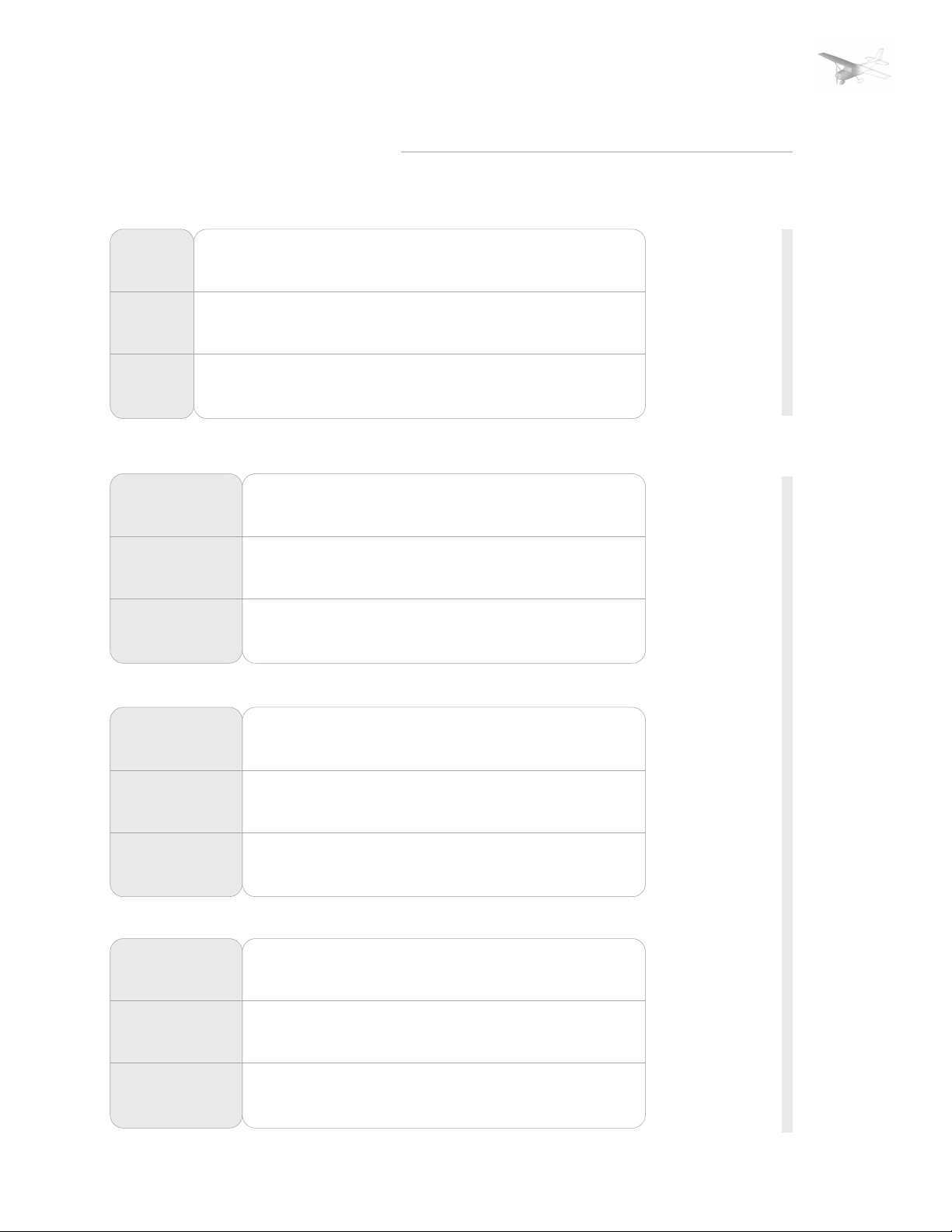
AIRSPEED CALIBRATION
CONDITION:
Power required for level flight or maximum rated RPM dive.
FLAPS UP
KIAS
KCAS
FLAPS 10°
KIAS
KCAS
FLAPS 30°
KIAS
KCAS
HEATER/VENTS AND WINDOWS CLOSED
FLAPS UP
NORMAL KIAS
ALTERNATE KIAS
FLAPS 10°
NORMAL KIAS
ALTERNATE KIAS
FLAPS 30°
NORMAL KIAS
ALTERNATE KIAS
50
56
40
49
40
47
60
62
50
55
50
53
50
51
40
40
40
48
70
70
60
62
60
61
60
61
50
51
50
50
80
79
70
70
70
70
70
71
60
61
60
60
90
89
80
79
80
80
80
82
70
71
70
70
100
98
90
89
85
84
90
91
80
81
80
79
110
107
100
98
---
---
100
101
90
90
85
83
120
117
110
108
---
---
110
111
100
130
126
99
---
---
---
---
---
---
120
121
110
108
---
---
140
135
---
---
---
---
130
131
---
---
---
---
150
145
---
---
---
---
140
141
---
---
---
---
160
154
---
---
---
---
PERFORMANCE
PAGE 4
NORMAL STATIC SOURCE
---
---
---
---
---
---
HEATER/VENTS OPEN AND WINDOWS CLOSED
FLAPS UP
NORMAL KIAS
ALTERNATE KIAS
FLAPS 10°
NORMAL KIAS
ALTERNATE KIAS
FLAPS 30°
NORMAL KIAS
ALTERNATE KIAS
WINDOWS OPEN
FLAPS UP
NORMAL KIAS
ALTERNATE KIAS
FLAPS 10°
NORMAL KIAS
ALTERNATE KIAS
FLIGHT SIMULATION USE ONLY
FLAPS 30°
NORMAL KIAS
ALTERNATE KIAS
40
36
40
38
40
34
40
26
40
25
40
25
50
48
50
49
50
47
50
43
50
43
50
41
60
70
59
60
59
60
57
60
57
60
57
60
54
80
70
80
70
80
69
79
70
80
67
77
70
80
70
82
70
80
69
80
70
80
67
78
Figure 5-1 Airspeed Calibration (Sheet 2 of 2)
90
89
90
88
85
81
90
93
90
91
85
84
100
99
100
97
---
---
100
103
100
101
---
---
110
108
110
106
---
---
110
113
110
111
---
---
120
118
---
---
---
---
120
123
---
---
---
---
130
128
---
---
---
---
130
133
---
---
---
---
ALTERNATE STATIC SOURCE
140
139
---
---
---
---
140
143
---
---
---
---
Page 32
SECTION: | 1 | 2 | 3 | 4 | 5 | 6 | SUPP |
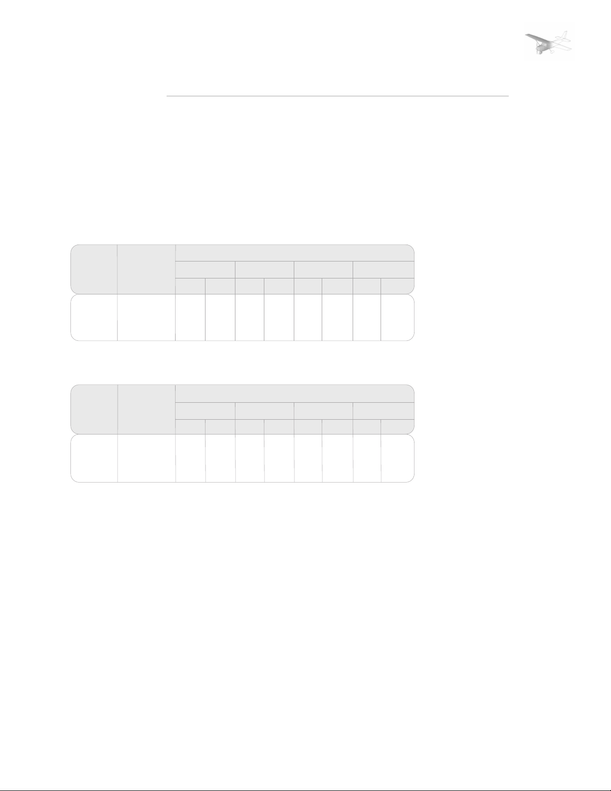
STALL SPEEDS
CONDITIONS:
Power Off
NOTES:
1. Altitude loss during a stall
recovery may be as much as 230
feet.
2. KIAS values are appoximate.
MOST REARWARD CENTER OF GRAVITY
ANGLE OF BANK
WEIGHT
LBS
2400
FLAP
DEFLECTION
UP
10°
30°
0° 30° 45° 60°
KIAS
KCAS
44
35
33
51
48
46
KIAS
47
38
35
KCAS
55
52
49
KIAS
52
42
39
KCAS
61
57
55
KIAS
62
49
47
PERFORMANCE
PAGE 5
KCAS
72
68
65
MOST FORWARD CENTER OF GRAVITY
WEIGHT
LBS
2400
FLAP
DEFLECTION
UP
10°
30°
0° 30° 45° 60°
KIAS
KCAS
44
52
37
49
33
46
ANGLE OF BANK
KIAS
KCAS
47
56
40
53
35
49
KIAS
KCAS
52
44
39
Figure 5-3 Stall Speeds
62
58
55
KIAS
62
52
47
KCAS
74
69
65
FLIGHT SIMULATION USE ONLY
Page 33

SECTION: | 1 | 2 | 3 | 4 | 5 | 6 | SUPP |
TAKEOFF DISTANCE
PERFORMANCE
PAGE 6
CONDITIONS:
FLAPS 10°
Full Throttle Prior to Brake
Release
Pavel, Level, Dry Runway
Zero Wind
Maximum Weight 2400 lbs
NOTES:
1. Short field technique as
specified in Section 4.
2. Prior to takeoff from fields
above 3000 feet elevation, the
TAKEOFF
SPEED
WEIGHT
LBS
KIAS
LIFT
OFFAT50 FT
56512400
54492200
PRESS
ALT
FT
S.L
1000
2000
3000
4000
5000
6000
7000
8000
S.L
1000
2000
3000
4000
5000
6000
7000
8000
GRND
ROLL
795
875
960
1055
1165
1285
1425
1580
1755
650
710
780
855
945
1040
1150
1270
1410
mixture should be leaned to give
maximum RPM in a full throttle,
static runup.
3. Decrease distances 10% for
each 9 knots headwind. For
operation with tailwinds up to 10
knots, increase distances by 10%
for each 2 knots.
4. For operation on a dry, grass
runway, increase distances by
15% of the „ground roll“ figure.
0°C 10°C 20°C 30°C 40°C
TOTAL
TO CLR
50 FT OBS
1460
1605
1770
1960
2185
2445
1755
3140
3615
1195
1310
1440
1585
1750
1945
2170
2440
2760
GRND
ROLL
860
940
1035
1140
1260
1390
1540
1710
1905
700
765
840
925
1020
1125
1240
1375
1525
TOTAL
TO CLR
50 FT OBS
1570
1725
1910
2120
2365
2660
3015
3450
4015
1280
1405
1545
1705
1890
2105
2355
1655
3016
GRND
ROLL
925
1015
1115
1230
1355
1500
1665
1850
2060
750
825
905
995
1100
1210
1340
1485
1650
TOTAL
TO CLR
50 FT OBS
1685
1860
2030
2295
2570
2895
3300
3805
4480
1375
1510
1660
1835
2040
2275
2555
2890
3305
GRND
ROLL
995
1090
1200
1325
1465
1620
1800
2000
- - - -
805
885
975
1070
1180
1305
1445
1605
1785
TOTAL
TO CLR
50 FT OBS
1810
2000
2220
2480
2790
3160
3620
4220
- - - -
1470
1615
1785
1975
2200
2465
2775
3155
3630
GRND
ROLL
1065
1170
1290
1425
1575
1745
1940
- - - -
- - - -
865
950
1045
1150
1270
1405
1555
1730
1925
50 FT OBS
TOTAL
TO CLR
1945
2155
2395
2685
3030
3455
3990
- - - -
- - - -
1575
1735
1915
2130
2375
2665
3020
3450
4005
525
S.L
51462000
1000
2000
3000
4000
5000
6000
7000
FLIGHT SIMULATION USE ONLY
8000
570
625
690
755
830
920
1015
1125
970
1080
1160
1270
1400
1545
1710
1900
2125
565
615
675
740
815
900
990
1095
1215
1035
1135
1240
1365
1500
1660
1845
2055
2305
605
665
725
800
880
970
1070
1180
1310
1110
1215
1330
1465
1615
1790
1990
2225
2500
650
710
780
860
945
1040
1150
1275
1410
1185
1295
1425
1570
1735
1925
2145
2405
2715
695
765
840
920
1015
1120
1235
1370
1520
1265
1385
1525
1685
1865
2070
2315
2605
2950
Figure 5-4. Takeoff Distance
Page 34
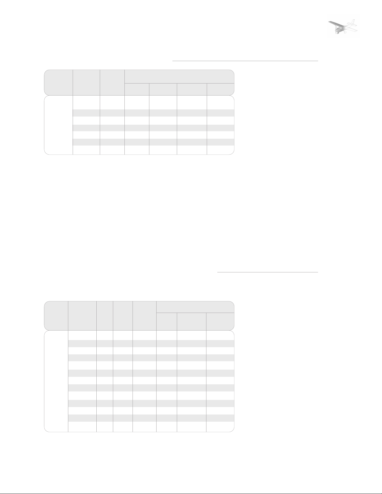
SECTION: | 1 | 2 | 3 | 4 | 5 | 6 | SUPP |
MAXIMUM RATE OF CLIMB
PERFORMANCE
PAGE 7
WEIGHT
LBS
2400
PRESS
ALT
FT
S.L.
2000
4000
6000
8000
10000
12000
CLIMB
SPEED
KIAS
76
75
74
73
72
71
70
RATE OF CLIMB - FPM
-20°
805
695
590
485
380
275
175
0°
745
640
535
430
330
225
125
Figure 5-5. Maximum Rate of Climb
20°
685
580
480
375
275
175
- - -
40°
625
525
420
320
220
- - -
- - -
CONDITIONS:
Flaps Up
Full Throttle
NOTE:
Mixture leaned above 3000
feet for maximum RPM:
TIME, FUEL AND DIATNCE TO CLIMB
MAXIMUM RATE OF CLIMB
WEIGHT
LBS
2400 S.L.
PRESSURE
ALTITUDE
FT
1000
2000
3000
4000
5000
6000
7000
8000
9000
10000
11000
12000
FLIGHT SIMULATION USE ONLY
CLIMB
TEMP
°C
15
13
11
9
7
5
3
1
-1
-3
-5
-7
-9
RATE OF
SPEED
KIAS
Figure 5-6. Time, Fuel, and Distance to Climb
76
76
75
75
74
74
73
72
72
71
71
70
70
CLIMB
FPM
700
655
610
560
515
470
425
375
330
285
240
190
145
FROM SEA LEVEL
TIME
MIN
0
1
3
5
7
9
11
14
17
20
24
29
35
FUEL USED
GALLONS
0.0
0.3
0.6
1.0
1.4
1.7
2.2
2.6
3.1
3.6
4.2
4.9
5.8
DISTANCE
NM
0
2
4
6
9
11
14
18
22
26
32
38
47
CONDITIONS:
Flaps Up
Full Throttle
Standard Temperature
NOTES:
1. Add 1.1 gallons of fuel
for engine start, taxi and
takeoff allowance.
2. Mixture leaned above
3000 feet for maximum RPM.
3. Increase time, fuel and
distance by 10% for each 10°C
above standard temp.
4. Distances shown are based
on zero wind.
Page 35

SECTION: | 1 | 2 | 3 | 4 | 5 | 6 | SUPP |
CRUISE PERFORMANCE
PERFORMANCE
PAGE 8
PRESS
ALT
FT
2000
4000
6000
RPM
2500
2400
2300
2200
2100
2550
2500
2400
2300
2200
2100
2600
2500
2400
2300
2200
2100
20°C BELOW
STANDARD TEMP
%
BHP KTAS GPH
- - 72
65
58
52
- - 72
69
62
56
51
- - 73
66
60
54
49
- - 110
104
- - 115
109
104
- - 114
108
103
99
92
98
91
96
90
- - -
8.1
7.3
6.6
6.0
- - -
8.6
7.8
7.0
6.3
5.8
- - -
8.2
7.4
6.7
6.1
5.7
STANDARD
TEMPERATURE
%
BHP KTAS GPH
76
69
62
55
50
76
73
65
59
54
48
77
69
63
57
52
47
114
109
103
117
114
108
102
119
113
107
101
97
91
96
89
95
88
8.5
7.7
6.9
6.3
5.8
8.5
8.1
7.3
6.6
6.1
5.7
8.6
7.8
7.0
6.4
5.9
5.5
20°C ABOVE
STANDARD TEMP
%
BHP KTAS GPH
72
65
59
53
48
72
69
62
57
51
47
72
66
60
55
50
46
114
108
102
116
113
107
101
118
112
106
96
89
94
88
99
92
86
8.1
7.3
6.6
6.1
5.7
8.1
7.7
7.0
6.4
5.9
5.5
8.1
7.4
6.7
6.2
5.8
5.5
CONDITIONS:
2400 Pounds
8000
10000
12000
2650
2600
2500
2400
2300
2200
2600
2500
2400
2300
2200
2550
250
2400
2300
77
70
63
57
52
74
67
61
55
50
67
64
59
53
- - 119
113
106
101
118
112
106
100
114
111
105
95
93
98
- - -
8.7
7.8
7.1
6.4
6.0
8.3
7.5
6.8
6.3
5.8
7.5
7.2
6.6
6.1
77
73
66
60
55
50
70
64
58
53
49
64
61
56
51
- - -
FLIGHT SIMULATION USE ONLY
121
118
112
106
100
117
111
105
112
109
103
8.6
8.2
7.4
6.7
6.2
93
5.8
7.8
7.1
6.5
98
6.0
91
5.7
7.1
6.8
6.3
96
5.9
Figure 5-7. Cruise Performance
73
69
63
58
53
49
66
61
56
51
47
61
59
54
50
120
117
111
104
97
91
115
109
102
96
89
111
107
100
94
8.1
7.8
7.1
6.5
6.0
5.7
7.4
6.8
6.3
5.9
5.6
6.9
6.6
6.1
5.8
Page 36
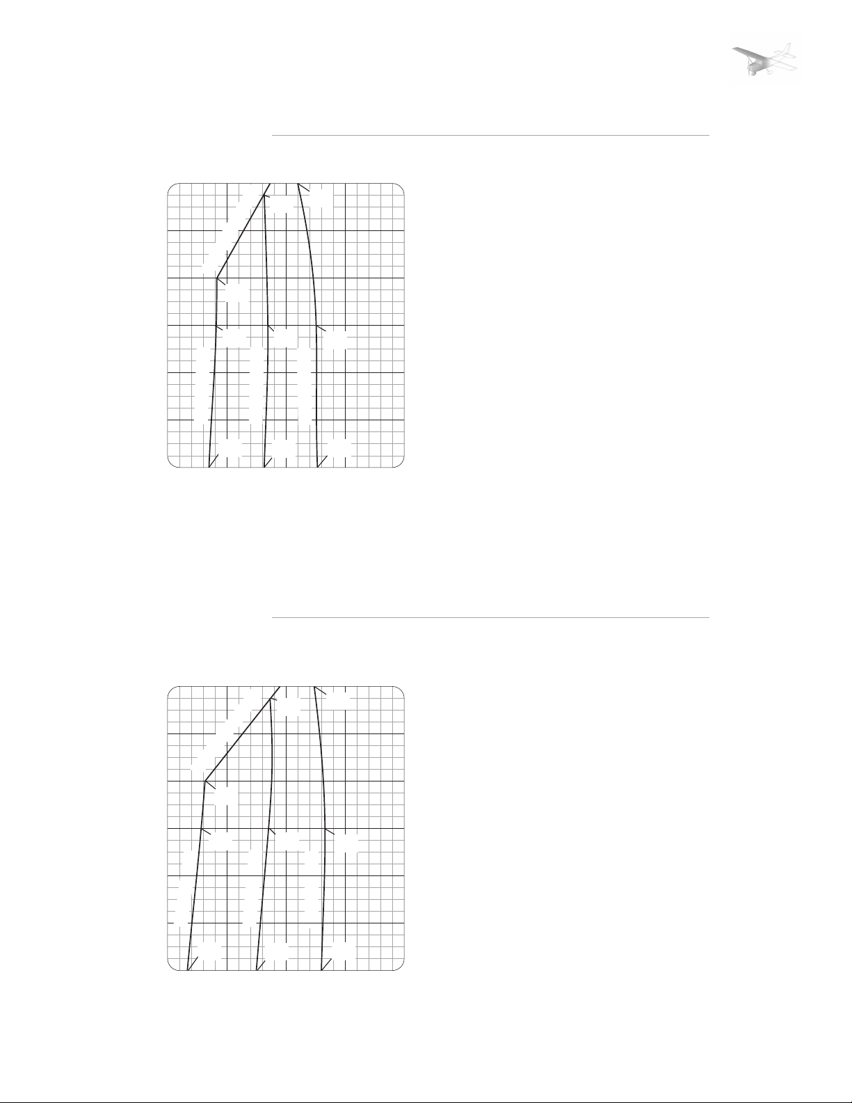
SECTION: | 1 | 2 | 3 | 4 | 5 | 6 | SUPP |
RANGE PROFILE
PERFORMANCE
PAGE 9
12000
10000
8000
6000
ALTITUDE - FEET
4000
2000
S.L.
101
114
KIAS
KIAS
FULL THROTTLE
120
KIAS
118
KIAS
75% POWER
112
KIAS
109
KIAS
65% POWER
105
KIAS
55% POWER
99
KIAS
96
KIAS
RANGE - NAUTICAL MILES
45 MINUTE RESERVE
40 GALLONS USABLE FUEL
CONDITIONS:
2400 Pounds
Recommended Lean Mixture for
Cruise
Standard Temperature
Zero Wind
Note:
This chart allows for the fuel used
for engine start, taxi, takeoff and
climb, and the
distance during climb
600550500450400
RANGE PROFILE
12000
114
KIAS
10000
FULL THROTTLE
8000
6000
ALTITUDE - FEET
4000
2000
FLIGHT SIMULATION USE ONLY
S.L.
120
KIAS
118
KIAS
75% POWER
112
KIAS
109
KIAS
65% POWER
105
KIAS
RANGE - NAUTICAL MILES
101
KIAS
99
KIAS
55% POWER
96
KIAS
45 MINUTE RESERVE
50 GALLONS USABLE FUEL
CONDITIONS:
2400 Pounds
Recommended Lean Mixture for
Cruise
Standard Temperature
Zero Wind
Note:
This chart allows for the fuel used
for engine start, taxi, takeoff and
climb, and the
distance during climb
750700650600550
Page 37
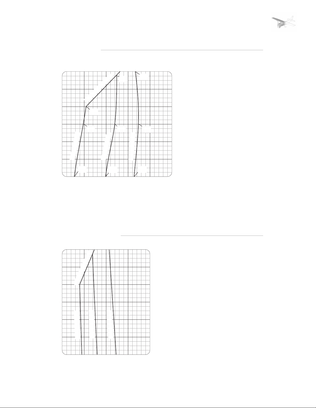
SECTION: | 1 | 2 | 3 | 4 | 5 | 6 | SUPP |
RANGE PROFILE
PERFORMANCE
PAGE 10
12000
10000
8000
6000
ALTITUDE - FEET
4000
2000
S.L.
FULL THROTTLE
120
KIAS
118
KIAS
75% POWER
112
KIAS
65% POWER
105
KIAS
RANGE - NAUTICAL MILES
114
KIAS
109
KIAS
101
KIAS
99
KIAS
55% POWER
96
KIAS
900850800750700
45 MINUTE RESERVE
62 GALLONS USABLE FUEL
CONDITIONS:
2400 Pounds
Recommended Lean Mixture for
Cruise
Standard Temperature
Zero Wind
Note:
This chart allows for the fuel used
for engine start, taxi, takeoff and
climb, and the
distance during climb
950
ENDURANCE PROFILE
12000
10000
8000
FULL THROTTLE
6000
ALTITUDE - FEET
4000
65% POWER
2000
75% POWER
55% POWER
S.L.
FLIGHT SIMULATION USE ONLY
ENDURANCE - HOURS
45 MINUTE RESERVE
40 GALLONS USABLE FUEL
CONDITIONS:
2400 Pounds
Recommended Lean Mixture for
Cruise
Standard Temperature
Note:
This chart allows for the fuel used
for engine start, taxi, takeoff and
climb, and the
distance during climb
76543
Page 38
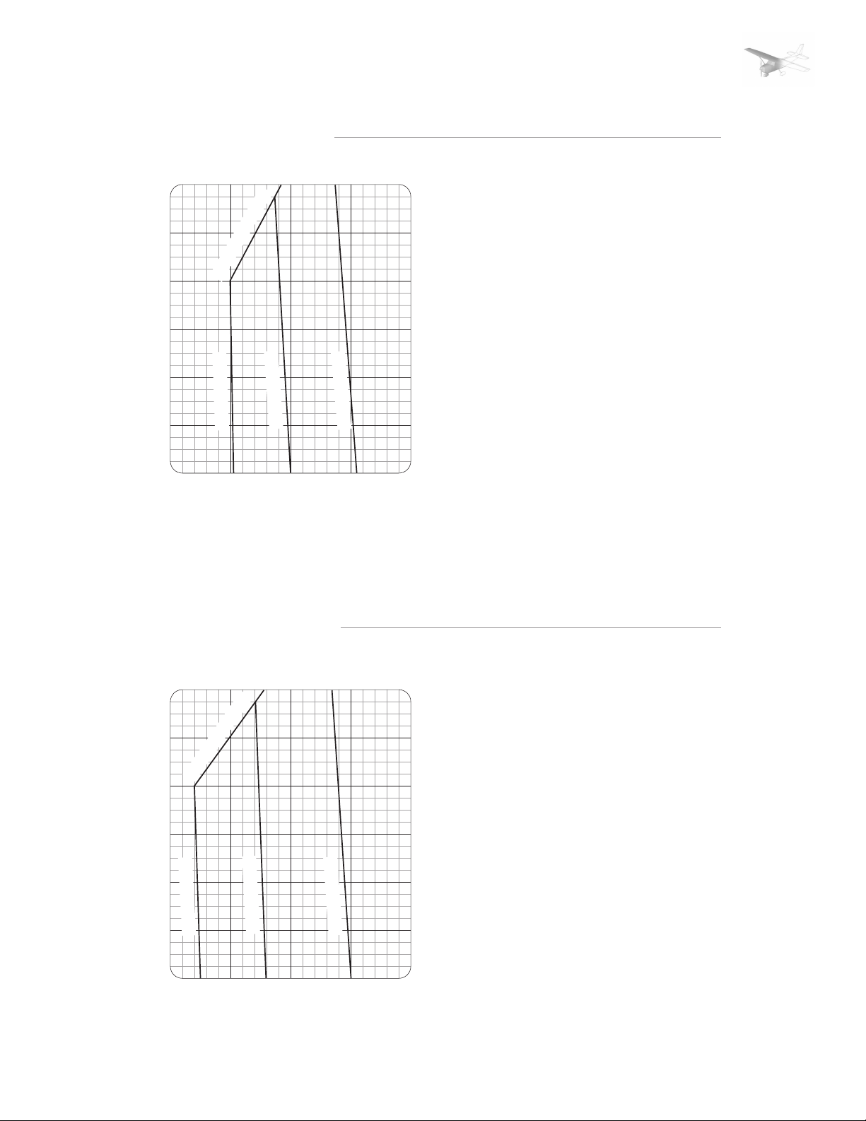
SECTION: | 1 | 2 | 3 | 4 | 5 | 6 | SUPP |
ENDURANCE PROFILE
PERFORMANCE
PAGE 11
12000
10000
8000
6000
ALTITUDE - FEET
4000
2000
S.L.
FULL THROTTLE
75% POWER
ENDURANCE - HOURS
65% POWER
55% POWER
87654
45 MINUTE RESERVE
50 GALLONS USABLE FUEL
CONDITIONS:
2400 Pounds
Recommended Lean Mixture for
Cruise
Standard Temperature
Note:
This chart allows for the fuel used
for engine start, taxi, takeoff and
climb, and the
distance during climb
ENDURANCE PROFILE
12000
10000
8000
6000
ALTITUDE - FEET
4000
2000
FLIGHT SIMULATION USE ONLY
S.L.
FULL THROTTLE
75% POWER
65% POWER
ENDURANCE - HOURS
55% POWER
45 MINUTE RESERVE
62 GALLONS USABLE FUEL
CONDITIONS:
2400 Pounds
Recommended Lean Mixture for
Cruise
Standard Temperature
Note:
This chart allows for the fuel used
for engine start, taxi, takeoff and
climb, and the
distance during climb
109876
Page 39

SECTION: | 1 | 2 | 3 | 4 | 5 | 6 | SUPP |
LANDING DISTANCE
CONDITIONS:
Flaps 30°
Power Off
Maximum Braking
Paved, Level, Dry Runway
Zero Wind
NOTES:
1. Short field technique as
specified in Section 4.
2. Decrease distances 10% for
each 9 knots headwind. For
operation with tailwinds up to 10
knots, increase distances by 10%
for each 2 knots.
4. For operation on a dry, grass
runway, increase distances by
15% of the „ground roll“ figure.
PERFORMANCE
PAGE 12
WEIGHT
LBS
2400
SPEED
AT
50 FT
KIAS
61
PRESS
ALT
FT
S.L
1000
2000
3000
4000
5000
6000
7000
8000
0°C 10°C 20°C 30°C 40°C
GRND
ROLL
510
530
550
570
595
615
640
665
690
TOTAL
TO CLR
50 FT OBS
1235
1265
1295
1330
1365
1400
1435
1475
1515
GRND
ROLL
530
550
570
590
615
640
660
690
715
TOTAL
TO CLR
50 FT OBS
1265
1295
1330
1360
1400
1435
1470
1515
1555
GRND
ROLL
550
570
590
615
635
660
685
710
740
TOTAL
TO CLR
50 FT OBS
1295
1325
1360
1395
1430
1470
1510
1550
1595
GRND
ROLL
570
590
610
635
660
685
710
735
765
TOTAL
TO CLR
50 FT OBS
1325
1360
1390
1430
1470
1510
1550
1590
1635
Figure 5-10. Landing Distance
GRND
ROLL
585
610
630
655
680
705
730
760
790
TOTAL
TO CLR
50 FT OBS
1350
1390
1425
1460
1500
1540
1580
1630
1675
FLIGHT SIMULATION USE ONLY
Page 40

SECTION: | 1 | 2 | 3 | 4 | 5 | 6 | SUPP |
SECTION 6
TABLE OF CONTENTS
AIRPLANE & SYSTEMS DESCRIPTION
TOC
•Instrument Panel
•Engine Oil System
•Inition-Starter System
•Air Induction System
•Carburetor and Priming System
•Cooling System
•Propeller
•Fuel System
•Brake System
•Electrical System
•Lighting
•Stall Warning System
•Avionivs Support Equipment
•Static Dischargers
•Pitot Static System and Instruments
•Vacuum System and Instruments
1
2
2
2
2
3
3
3
4
4
6
6
6
6
7
7
FLIGHT SIMULATION USE ONLY
Page 41
SECTION: | 1 | 2 | 3 | 4 | 5 | 6 | SUPP |
AIRPLANE & SYSTEMS DESCRIPTION
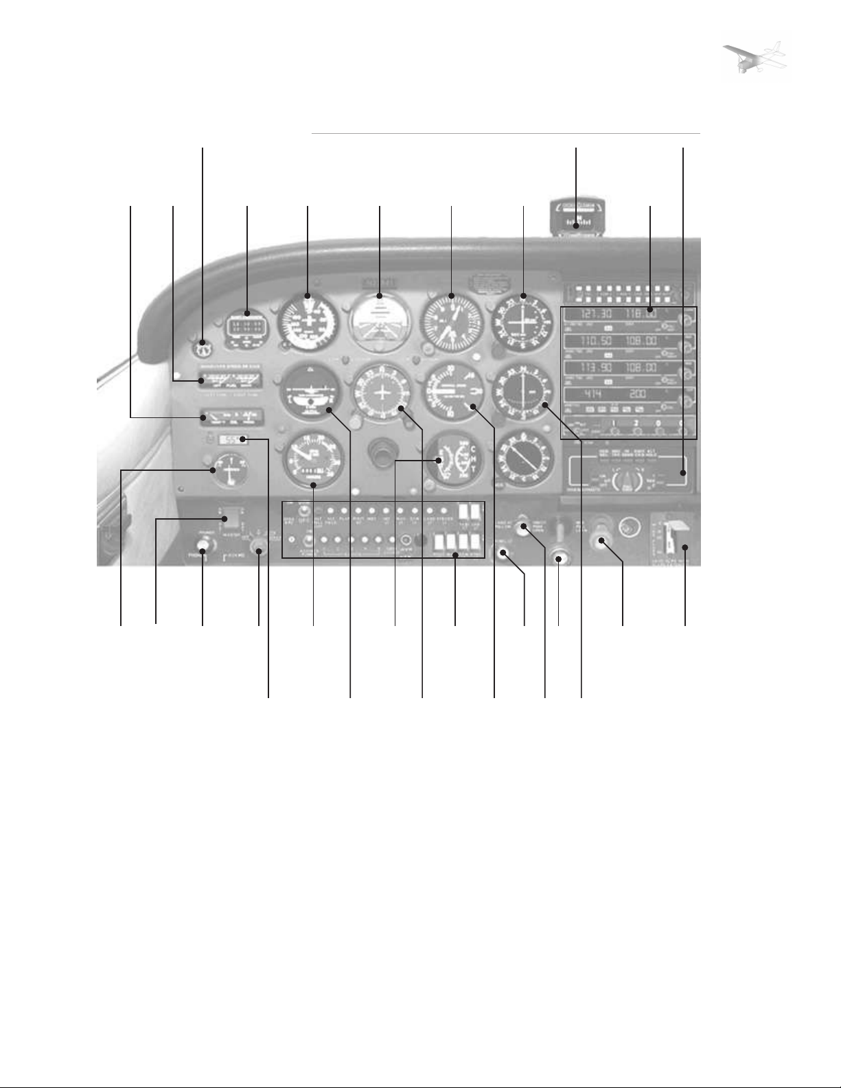
INSTRUMENT PANEL
3 9 11
1 2 4 5 6 7 8 10
PAGE 1
12 13 14 15 17 19 21 23 25 27 28
16 18 20 22 24 26
1. Oil Temperature/Oil Pressure
2. Fuel Quantity Indicators
3. Suction gage
4. Clock/Timer
5. Air Spee Indicator
6. Attitude Indicator
7. Altimeter
8. Course Deviation Indicator
9. Magnetic Compass
10. COM/NAV Radios
11. Autopilot
12. Ammeter
13. Master Switch
14. Primer
15. Ignition Switch
16. Thermometer
17. Tachometer
18. Turn Coordinator
19. RGT / CHT
20. Heading Indicator
21. Circuit Breakers/Light
Switches
22. Vertical Speed Indicator
23. Instrument Lighting Dimmer
24. Carburetor Heat
25. Throttle Control
26. Course Deviation Indicator
27. Mixture Control
28. Wing Flap Switch
FLIGHT SIMULATION USE ONLY
Page 42

SECTION: | 1 | 2 | 3 | 4 | 5 | 6 | SUPP |
ENGINE OIL SYSTEM
AIRPLANE & SYSTEMS DESCRIPTION
PAGE 2
Oil for the engine lubrication is
supplied from a sump at the
bottom of the engine. The
capacity of the enfine sump is
seven quarts (one additional
quart is contained in the full flow
oil filter. Oil is drawn from the
sump through an oil suction
strainer screen into the enginedriven oil pump. From the pump
oil is routed to a bypass valve. If
the oil is cold, the bypass valve
allows the oil to bypass the oil
cooler and go directly from the
pump to the full flow oil filter. If
the oil is hot, the bypass valve
routes the oil out of the accessory
housing and into a flexible hose
leading to the oil cooler on the
right rear engine baffle. Pressure
oil from the cooler returns to the
accessory housing where it passes
through the full flow oil filter.
The filter oil then enters a
pressure relief valve which
regulates engine oil pressure by
allowing excessive oil to return
to the sump while the balance of
the oil is circulated to various
engine parts for lubrication.
IGNITION-STARTER SYSTEM
Engine ignition is provided by
two engine-driven magnetos, and
two spark plugs in each cylinder.
The right magneto fires the lower
right and upper right spark-plugs.
Normal operation is conducted
with both magnetos due to the
more complete burning of the
fuel-air mixture with dual
ignition.
Ignition and starter operation is
controlled by a rotary type switch
located on the left switch and
control panel. The switch is
labelled clockwise: OFF, R, L,
BOTH and START. The engine
should be operated on BOTH
magnetos except for
magnetochecks. The R and L
position are for checking
Residual oil is returned to sump
by gravity flow.
An oil filter cap/oil dipstick is
located at the right rear of the
engine. The filler cap/dipstick is
accesible through an access door
on the top right side of the engine
cownling. The engine should not
be operated on less that five
quarts of oil. For extended flight
fill to seven quarts (dipstick
indication only). •
purposes and emergency use
only. When the switch is rotated
to the spring-loaded STARTposition, the starter contactor is
energized and the starter will
crank the engine. When the
switch is released, it will
automatically return to the BOTHposition. •
AIR INDUCTION SYSTEM
The engine air induction system
receives ram air through an
intake in the lower front portion
of the engine cowling. The intake
is covered by an air-filter which
removes dust and other foreign
matter from the induction air.
Airflow passing through the filter
enters an airbox. After passing
through the airbox, induction air
enters the inlet in the carburetor
which is under the engine, and
is then ducted to the engine
cylinders through intake manifold
tubes. In the event carburetor ice
is encountered or the intake filter
becomes blocked, alternate
heated air can beobtained from
a shroud around an exhaust riser
through a duct to a valve in the
CARBURETOR AND PRIMING SYSTEM
The engine is equipped with an
up-draft, float-type, jetcarburetor
mounted on the bottom of the
engine. The carburetor is
equipped with an enclosed
accelerator pump, an idle cut-off
mechanism and a manual mixture
FLIGHT SIMULATION USE ONLY
control. Fuel is delivered to the
carburetor by gravity flow from
the fuel system. In the carburetor,
fuel is atomized, properly mixed
with intake air and delivered to
the cylinders through intake
manifold tubes. The proportion
of atomized fuel to air may be
controlled, within limits, by the
mixture control on the instrument
panel.
airbox operated by the carburetor
heat control on the instrument
panel. Heated air from the shroud
is obtained from an unfiltered
outside source. Use of full
carburetor heat at full throttle
will result in a loss of
approximately 75 to 150 RPM.
•
For easy starting in cool weather,
the engine is equipped with a
manual primer. The primer is
actually a small pump which
draws fuel from the fuel strainer
when the plunger is pulled out,
and injects it into the cylinder
intake ports when the plunger is
pushed back in. •
Page 43
SECTION: | 1 | 2 | 3 | 4 | 5 | 6 | SUPP |
COOLING SYSTEM
AIRPLANE & SYSTEMS DESCRIPTION
PAGE 3
Ram air for engine cooling enters
through two intake openings in
the front of the engine cowling.
The cooling air is directed around
the cylinders and other areas of
the engine by baffling, and is then
exhausted through an opening at
the bottom aft edge of the
PROPELLER
The airplane is equipped with a
two-bladed, fixed-pitch, one-piece
forged aluminium alloy propeller
wich is anodized to retard
FUEL SYSTEM
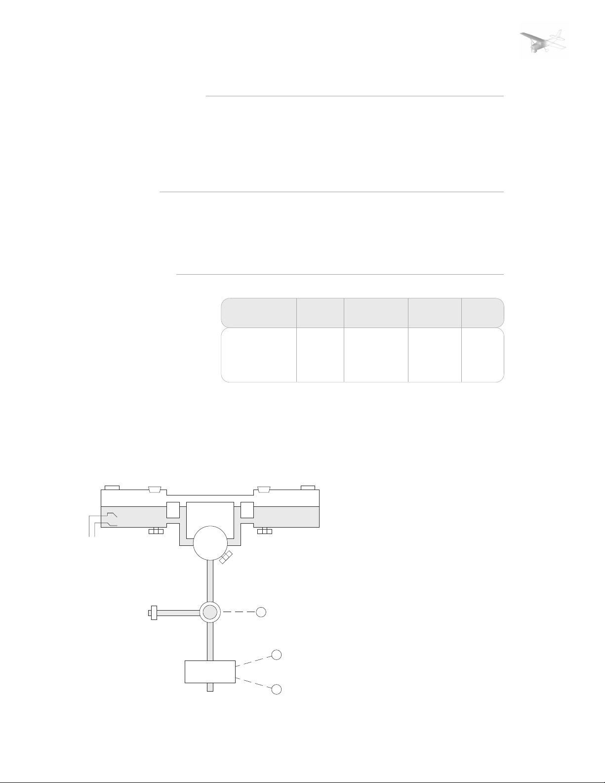
The airplane may be equipped
with a standard fuel system or
either of two long range systems.
Each system consists of two
vented fuel tanks (one tank each
wing), a four-position selector
valve, fuel strainer, manual
primer, and carburetor. The 68gallon long-range system utilizes
integral tanks and the other two
systems employ removable
aluminium tanks. Fuel flows by
gravity from the two wing tanks
to a four-position selector valve
labelled BOTH, LEFT, RIGHT and
fuel quantity
tansmitter
left fuel tank
vent with
check valve
to engine
drain
valve
fuel
strainer
engine
primer
carburetor
selector
valve
FUEL TANKS
STANDARD
LONG RANGE
LONG RANGE
(INTEGRAL)
OFF. With the selector valve in
either the BOTH, LEFT or RIGHT
position, fuel flows through a
strainer to the carburetor. From
the carburetor, mixed fuel and
air flows to the cylinders through
vented filler capfiller cap
drain
valve
selector valve
drain plug
FLIGHT SIMULATION USE ONLY
to
engine
fuel quantity
tansmitter
right fuel tank
fuel
strainer
crain
control
throttle
control
mixture
control
FUEL
LEVEL
FULL
FULL
FULL
cowling. No manual cooling
system control is provided.
•
corrosion. The propeller is 75
inches in diameter. •
TOTAL FUEL
TOTAL
UNUSABLE
43
54
68
3
4
6
intake manifold tubes. The
manual primer draws its fue from
the fuel strainer and injects it
into the cylinder intake ports.
Fuel system venting is essential
to system operation. Blockage
of the system will result in
decreasing fuel flow and eventual
engine stoppage. Venting is
accomlished by an
interconnecting line from the
right fuel tank to the left fuel
tank. The left fuel tank is vented
overboard through a vent line,
equipped with a check valve,
which protrudes from the bottom
surface of the left wing near the
wing strut. The right fuel tank
filler cap is also vented.
When long range integral tanks
are installed, the airplane may be
serviced to a reduced capacity to
permit heavier cabin loadings.
This is accomplished by filling
each tank to the bottom edge of
the fuel filler collar, thus giving
a reduced fuelload of 24 gallons
in each tank.
Fuel Quantity is measured by two
float-type fuel quantity
transmitters and indicated by two
elictrically-operated fuel quantity
TOTAL
USABLE
40
50
62
Page 44

SECTION: | 1 | 2 | 3 | 4 | 5 | 6 | SUPP |
AIRPLANE & SYSTEMS DESCRIPTION
PAGE 4
indicators on the left side of the
instrument panel. An empty tank
is indicated by a red line and the
letter E. When an indicator shows
an empty tank, approximately
1.5 gallons remain in a standard
tank, and 2 gallons remain in a
long range tank (3 gallons when
long range integral tanks are
installes) as unusable fuel. The
indicators cannot be relied upon
for accurate readings during
skids, slips, or unusual attitudes.
The fuel selector valve should be
in BOTH position for takeoff,
climb, landing and maneuvers
that involve prolonged slips or
skids. Operation from either LEFT
or RIGHT tank is reserved for
cruising flight.
NOTE1:
When the fuel selector valve
handle is in the BOTH position in
cruising flight, unequal fuel flow
from each tank may occur if the
wings are not maintained exactly
level. Resulting wing heaviness
can be alleviated gradually by
turning the selector valve handle
to the tank in the heavy wing.
NOTE2:
When the fuel tanks are 1/4 full
or less, prolonged uncoordinated
flight such as slips or skids can
cover the fuel tank outlets.
Therefor, if operating with one
fuel tank dry or if operating on
LEFT or RIGHT tank when 1/4 full
or less, do not allow the airplane
to remain in uncoordinated flight
for periods in excess of 30
seconds.
NOTE3:
It is not practical to measure the
time required to consume all of
the fuel in one tank, and, after
switching to the opposite tank,
expect an equal duration from
the remaining fuel. The airspace
in both fuel tanks is
interconnected by a vent line and,
therefor, some sloshing of fuel
between tanks can be expected
when the tanks are nearly full
and the wings are not level.
The fuel system is equipped with
drain valves to provide a means
for the examination of fuel in the
system foe contamination and
grade. The system should be
examined before the first flight
of every day and after each
refueling, by using the sampler
cup provided to drain fuel from
the wing tank sumps, and by
utilizing the fuel strainer drain
under an access door on the aft
right side of the top engine
cowling. If takeoff weight
limitations for the next flight
permit, the fuel tanks shoul be
filled after each flight to prevent
condensation.
•
BRAKE SYSTEM
The airplane has a singe -disc,
hydraulically-actuated brake on
ech main landing gear wheel.
Each brake is connected, by a
hydraulic line, to a master
cylinder attached to each of the
pilot‘s rudder pedals. The brakes
are operated by applying
pressure to the top of either the
left (pilot‘s) or right (copilot‘s)
set of rudder pedals, which are
interconnected. When the
airplane is parked, both main
wheel brakes may be set by
utilizing the parking brake which
is operated by a handle under
the left side of the instrument
panel. To apply the parking
brake, set the brakes with the
rudder pedals, pull the handle
aft, and rotate it 90° down.
For maximum brake life, keep the
brake system properly
maintained, and minimize brake
usage during taxi operations and
landings.
Some of the symtoms of
impending brake failure are:
gradual decrease in braking
action after brake application,
noisy or dragging brakes, soft or
spongy pedals, and excessive
ELECTRICAL SYSTEM
The airplane is equipped with a
28-volt, direct-current, electrical
system. The system is powered
by a belt-driven, 60-amp
alternator and a 24-volt battery,
located on the left forward side
FLIGHT SIMULATION USE ONLY
of the firewall. Power is supplied
to most general electrical and all
avionics circuits through the
primary bus bar and the avionics
bus bar, which is interconnected
by an avionics power switch. The
primary bus is on anytime the
master switch is turned on, and
is not affected by starter or
external power usage. Both bus
travel and weak braking action.
If any of these symptoms appear,
the brake system is in need of
immediate attention. If, during
taxi or landing roll, braking action
decreases, let up on the pedals
and then re-apply the brakes with
heavy pressure. If the brakes
become spongy or pedal travel
increases, pumping the pedals
should build braking pressure. If
one brake becomes weak or fails,
use the other brake sparingly
while using opposite rudder, as
required, to offset the good brake.
•
bars are on anytime the master
and avionics power switches are
turned on.
CAUTION:
Prior to turning the master switch
on or off, starting the engine or
applying an external power
Page 45

SECTION: | 1 | 2 | 3 | 4 | 5 | 6 | SUPP |
AIRPLANE & SYSTEMS DESCRIPTION
PAGE 5
source, the avionics power switch,
labeled AVIONICS POWER, should
be turned off to prevent any
harmful transient voltage from
damaging the avionics
equipment.
MASTER SWITCH
The master switch is a split
rocker-type switch labeled
MASTER, and is ON in the up
position. The right half of the
switch labeled BAT controls all
the electrical power to the
airplane. The left half, labeled
ALT controls the alternator.
Normally, both sides of the master
switch should be used
simultaneously; however, the BAT
side of the switch could be turned
on seperately to check equipment
while on the ground. To check or
use avionics equipment or radios
while on the ground, the avionics
power switch must also be turned
on. The ALT side of the switch,
when placed in the OFF position,
removes the alternator from the
electrical system. While this
switch in the OFF position, the
entire electrical load is placed on
the battery. Continued operation
with the alternator switch in the
OFF position will reduce battery
power low enough to open the
battery contactor, remove power
from the alternator field, and
prevent alternator restart.
AVIONICS POWER SWITCH
Electrical power from the airplane
primary bus to the avionics bus
is controlled by a toggle
switch/circuit braker labeled
AVIONICS POWER. The switch is
located on the left side of the
switch and control panel and is
ON in the up position. With the
switch in the OFF position, no
electrical power will be applied
to the avionics equipment,
regardless of the position of the
master switch or the individual
equipment switches. The avionics
power switch also functions as a
circuit breaker. If an electrical
malfunction should occur and
cause the circuit braker to open,
FLIGHT SIMULATION USE ONLY
electrical power to the avionics
equipment will be interrupted
and the switch will automatically
move to OFF position. If this
occurs, allow the circuit breaker
to cool for about two minutes
before placing the switch in the
ON position again. If the circuit
breaker opens again, do not reset
it. The avionics power switch
should be placed in the OFF
position prior to turning the
master switch ON or OFF, starting
the engine, or applying an
external power sourve, and may
be utilized in place of the
individual avionics equipment
switches.
AMMETER
The ammeter, located on the
lower left side of the instrument
panel, indicates the amount of
current in amperes, from the
alternator to the battery or from
the battery to the airplane
electrical system. When the
engine is operating and the
master switch is turned on, the
ammeter indicates the charging
rate applied to the battery. In the
event the alternator is not
functioning or the elctrical load
exceeds the output of the
alternator, the ammeter indicates
the battery discharge rate.
ALTERNATOR CONTROL UNIT
AND LOW-VOLTAGE
WARNING LIGHT
The airplane is equipped with a
combination alternator regular
high-low voltage control unit
mounted on the engine side of
the firewall and a red warning
light , labeled LOW VOLTAGE, on
the left side of the instrument
panel below the ammeter.
In the event an over-voltage
condition occurs, the alternator
control unit automatically
removes alternator field current
which shuts down the alternator.
The battery will then supply
system current as shown by a
discharge rate on the ammeter.
Under these conditions,
depending on electrical system
load, the low-voltage warning
light will illuminate when system
voltage drops below normal. The
alternator control unit may be
reset by turning the master switch
off and back on again. If the
warning light does not illuminate
again, a malfunction has occured,
and the flight should be
terminated as soon as practical.
CIRCUIT BREAKERS AND
FUSES
Most of the elecrical circuits in
the airplane are protected by
„push-to-reset“ type circuit
breakers mounted on the left side
of the switch and control panel.
However, circuit breakers
protecting the alternator output
and the strobe light/avionics
cooling fan circuits are the „pulloff“ type. In addition to the
individual circuit breakers, a
toggle switch/circuit breaker,
labeled AVIONICS POWER, on the
left side of the switch and control
panel, also protects the avionics
system. The control wheel map
light (if installed) is protected by
the NAV LT circuit breaker and
a fuse behind the instrument
panel. Electrical circuits which
are not protected by circuit
breakers are the battery contactor
closing (external power) circuit,
clock circuit, and flight hour
recorder circuit. These circuits
are protected by fuses mounted
adjacent to the battery. •
Page 46

SECTION: | 1 | 2 | 3 | 4 | 5 | 6 | SUPP |
LIGHTING
AIRPLANE & SYSTEMS DESCRIPTION
PAGE 6
Conventional navigation lights
are located on the wing tips and
top of the rudder. A single
landing light is located in the
cowl nose cap. Dual landing/taxi
lights are available and also
located in the cowl nose cap.
Additional lighting is available
and includes a flashing beacon
mounted on top of the vertical
fin, a strobe light on each wing
tip, and a courtesy light recessed
into the lower surface of each
wing slightly outboard of the
cabin doors.
The flashing beacon should not
be used when flying through
clouds or overcast; the flashing
light reflected from the water
droplets or particles in the
atmosphere, particularly at night
can produce vertigo and loss of
orientation. •
STALL WARNING SYSTEM
The airplane is equipped with a
pneumatic-type stall warning
system consisting of an inlet in
the leading edge of the left wing
and an air-operated horn near
the upper left corner of the
windshield. As the airplane
approaches a stall, the low
pressure on the upper surface of
the wings moves forward around
the leading edge of the wings.
This low pressure creates a
AVIONICS SUPPORT EQUIPMENT
If the airplane is equipped with
avionics, various avionics support
equipment may also be installed.
Equipment available includes an
avionics cooling fan, microphoneheadset installations and control
STATIC DISCHARGERS
If frequent IFR flights are planned,
installation of wick-type static
dischargers is recommended to
improve radio communications
FLIGHT SIMULATION USE ONLY
during flight through dust or
various forms of precepitation.
Under these conditions, the build-
up and discharge of static
electricity from the trailing edges
of the wings, rudder, elevator,
propeller tips and radio antennas
can result in loss of usable radio
signals on all communications
and navigation equipment.
differential pressure in the stall
warning system which draws air
through the warning horn,
resultig in an audible warning at
5 to 10 knots above stall. •
surface dischargers. •
Usually the ADF is first to be
affected and VHF communication
equipment is the last to be
affected. •
Page 47
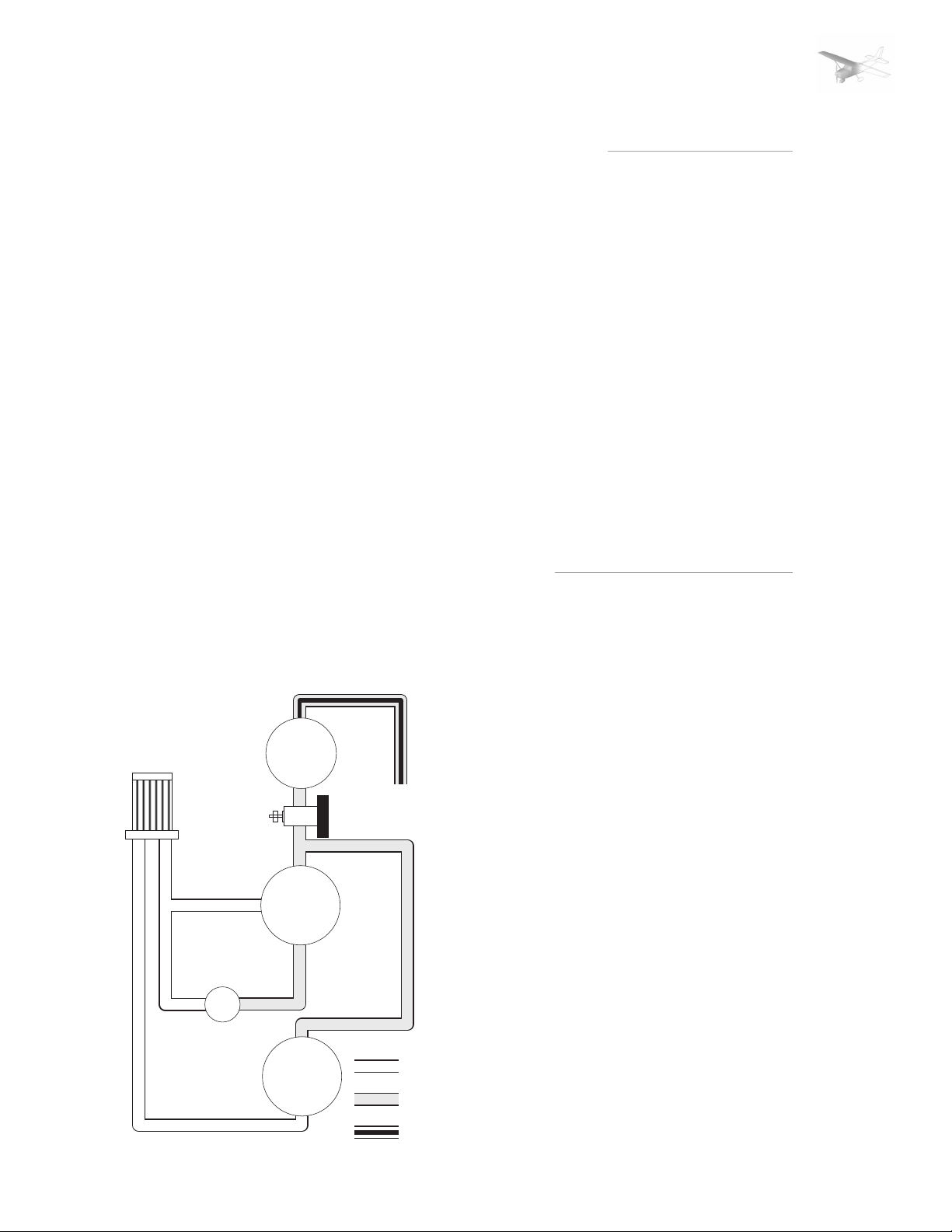
SECTION: | 1 | 2 | 3 | 4 | 5 | 6 | SUPP |
AIRPLANE & SYSTEMS DESCRIPTION
PITOT STATIC SYSTEM AND INSTRUMENTS
PAGE 7
The pitot-static system supplies
ram air pressure to the airspeed
indicator and static pressure to
the air speed indicator, vertical
speed indicator and altimeter.
The system is composed of either
an unheated or heated pitot tube
mounted on the lower surface of
the left wing, an external static
port on the lower left side of the
forward fuselage, and the
associated plumbing necessary
to connect the instruments to the
sources. The heated pitot system
(if installed) consists of a heating
element in the pitot tube, a rocker
switch labeld PITOT HT, a 5-amp
circuit breaker, and associated
wiring.
A static pressure alternate source
valve may be installed on the
switch and control panel below
the throttle, and can be used if
the external static pressure source
is malfunctioning.
AIRSPEED INDICATOR
The airspeed indicator is
calibrated in knots. Limitation
and range markings include the
white arc, green arc, yellow arc
and a red line.
VERTICAL SPEED INDICATOR
The vertical speed indicator
depicts airplane rate of climb and
descent in feet per minute. The
pointer is actuated by
atmospheric pressure changes
resulting from changes of altitude
VACUUM SYSTEM AND INSTRUMENTS
An engine-driven vacuum system
provides the suction necessary
to operate the attitude indicator
and directional indicator. The
system consistes of a vacuum
pump mounted on the engine, a
vacuum system
air filter
suction
gage
FLIGHT SIMULATION USE ONLY
vacuum
pump
attitude
indicator
directional
indicator
vacuum relief valve and vacuum
system airfilter on the left side
of the firewall below the
instrument panel, and
instruments on the left side of
the instrument panel.
overboard
vent line
vacuum relief
valve
inlet air
vacuum
discharge air
as supplied by static source.
ALTIMETER
Airplane altitude is depicted by
a barometric type altimeter. A
knob near the lower left portion
of the indicator provides
adjustment of the instrument‘s
barometric scale to the current
altimeter setting. •
ATTITUDE INDICATOR
The attitude indicator gives a
visual indication of flight attitude.
Bank attitude is presented by a
pointer at the top of the indicator
relative to the bank scale which
has index marks at 10°, 20°, 30°,
60° and 90° either side of the
center mark. Pitch and roll
attitudes are presented by a
miniature airplane superimposed
over a symbolic horizon area
divided into two sections by a
white horizon bar.
DIRECTIONAL INDICATOR
A directional indicator displays
airplane heading on a compass
card in relation to a fixed
simulated airplane image and
index. The indicator will precess
slightly over a period of time.
Therefor the compass card should
be set in accordance with the
magnetic compass just prior to
takeoff, and occasionally readjusted on extended flights.
SUCTION GAGE
The suction gage is calibrated in
inches mercury and indicates
suction available for operation of
the attitude and directional
indicators. •
Page 48

SECTION: | 1 | 2 | 3 | 4 | 5 | 6 | SUPP |
SUPPLEMENT
TABLE OF CONTENTS
SUPLEMENTS
TOC
•Digital Clock/Timer
•Cessna 400 Glide Slope
•Autopilot
•Autopilot Procedures
-Before Takeoff and Landing
-Inflight Wings Leveling
-NAV Intercept (VOR/LOC)
-NAV Tracking (VOR/LOC)
-Heading Select
1
1
2
2
2
2
3
3
3
FLIGHT SIMULATION USE ONLY
Page 49
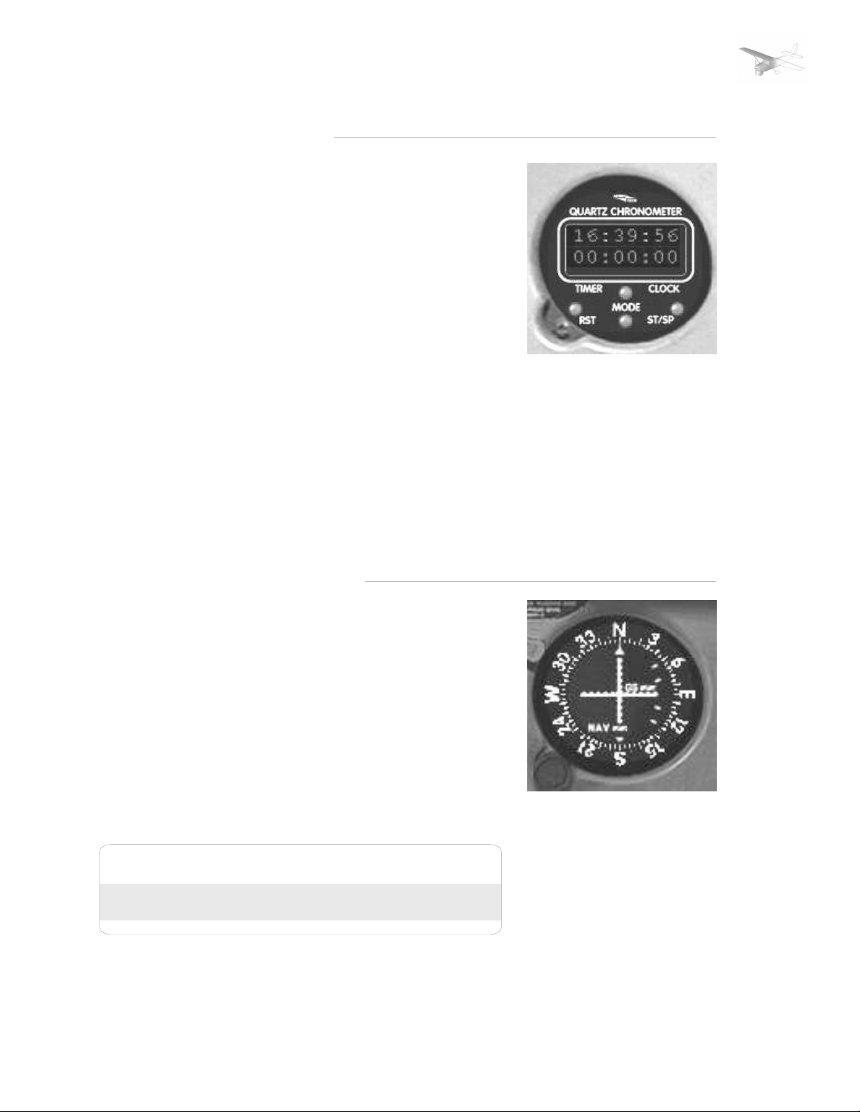
SECTION: | 1 | 2 | 3 | 4 | 5 | 6 | SUPP |
DIGITAL CLOCK/TIMER
SUPPLEMENTS
PAGE 1
The Astro Tech LC-2 Quartz
Chronometer is a precision, solid
state time keeping device which
will display to the pilot the timeof-day, the calendar date, and
the elapsed time interval between
a series of selected events, such
as in-flight check points or legs
of a cross-country flight, etc.
These three modes of operation
fuction independently and can
be alternately selected for viewing
in the liquid crystal display (LCD)
on the front face of the
instrument. Four push button
type switches directly below the
display control all time keeping
functions.
The digital display features an
internal light to ensure good
visibility under low cabin lighting
conditions or at night.
Buttons:
ST/SP
Starts and Stops the Stopwatch
RST
Resets the Stopwatch
Lower MODE
Toggles between Stopwatch /
Simulation Speed / Zoom Factor
Upper Mode
Switches between Local Time and
Zulu Time (indicated by a yellow
spot)
CESSNA 400 GLIDE SLOPE
The Cessna 400 Glide Slope is an
airborne navigation receiver
which receives and interprets
glide slope signals from a groundbased Instrument Landing System
(ILS). It is used with the localizer
function of a VHF navigation
system when making instrument
approaches to an airport. The
glide slope provides vertical path
guidance while the localizer
provides horizontal track
guidance.
TO RECEIVE GLIDE SLOPE SIGNALS
[1] NAV Frequency
Select Knob --- Select desired localizer
The Cessna 400 Glide Slope
system consists of a remotemounted receiver coupled to an
existing navigation system, a
panel-mounted indicator and an
externally mounted antenna.
Operation of the Cessna 400 Glide
Slope system is controlled by the
associated navigation system.
FLIGHT SIMULATION USE ONLY
Page 50
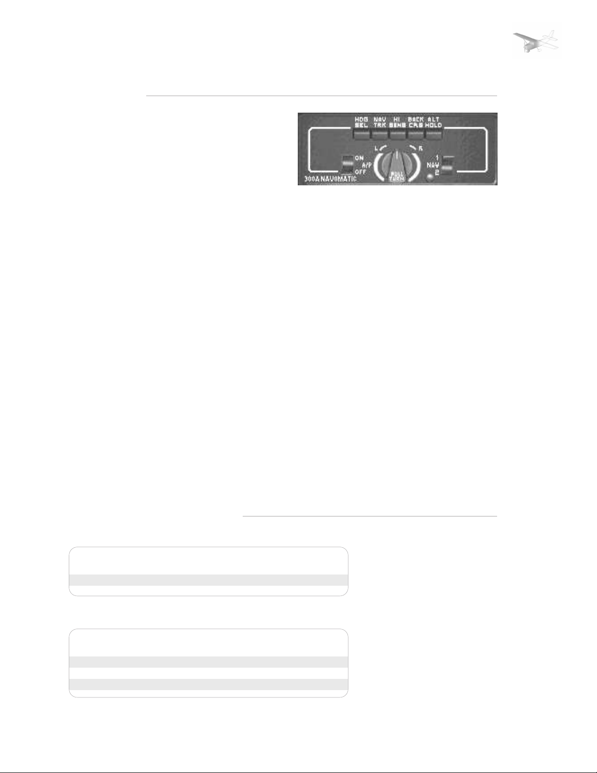
SECTION: | 1 | 2 | 3 | 4 | 5 | 6 | SUPP |
AUTOPILOT
SUPPLEMENTS
PAGE 2
GENERAL INFORMATION
The installed autopilot is a singleaxis (aileron control) autopilot
with an additional altitude hold
and glide slope hold function.
Roll and yaw motions of the
airplane are sensed by the turn
coordinator gyro. Deviation from
the selected heading are sensed
by the directional gyro. The
computer-amplifier electronically
computes the necessary
correction and signals the
actuator to move the ailerons to
maintain the airplane in the
commanded lateral attitude or
heading.
BUTTONS
ON/OFF
The autopilot can be activated
via the on/off switch located to
the left of the large center knob.
The switch will turn to the offposition when the battery is
switched off.
HDG SEL
By engaging this button the
airplane will turn to and maintain
the heading
selected via the
bug on the
directional
indicator.
NAV TRK
By engaging this
button the airplane will hold a
radial selected on NAV1. It is
possible to engage both HDG SEL
and NAV TRK simultanously. HDG
SEL is given priority until a VOR
radial is intercepted, at which
point the HDG SEL button will
disengage and the aircraft will
turn to and track the radial. This
mode is generally unavailable if
an active frequency is not
selected.
HI SENS
By depressing this button the
aircraft will track a localizer
frontcourse and also the glide
slope.
BCK CRS
This mode permits tracking of
the back course localizer.
generally unavailable if an active
frequency is not selected.
CENTER BANK KNOB
The center knob provides variable
aileron control to execute a
standard rate turn. In the default
state, the knob is off (pushed in).
Clicking on the center of the knob
will pull it in the on position,
engaging the wing leveler.
With the knob pulled out moving
it into the right position the
aircraft will enter a standard rate
turn to the right. Moving it into
the left position the aircraft will
enter a standard rate turn to the
left. Re-centering the knob from
either the left or right position
will re-engage the wing leveler.
AUTOPILOT PROCEDURES
BEFORE TAKE-OFF AND LANDING
[1] A/P on/off switch --- OFF
INFLIGHT WINGS LEVELING
[1] Rudder Trim --- ADJUST for zero slip
[2] A/P turn knob --- CENTER and PULL out
FLIGHT SIMULATION USE ONLY
[3] A/P on/off switch --- ON
Page 51

SECTION: | 1 | 2 | 3 | 4 | 5 | 6 | SUPP |
NAV INTERCEPT (VOR/LOC)
[1] A/P turn knob --- CENTER and PULL
[2] NAV Receiver OBS --- SET desired course
[3] Heading Selector --- ROTATE bug to selected
course
[4] Directional Gyro --- SET for magnetic
heading
[5] HI SENS button --- PUSH for localizer
intercepts
[6] BCK CRS button --- PUSH ONLY if inter-
cepting front course
outbound or back
course inbound
[7] A/P turn knob --- PUSH
NAV TRACKING (VOR/LOC)
SUPPLEMENTS
PAGE 3
CAUTION:
With BCK CRS button pushed
in and localizer frequency
selected, the CDI on selected
nav radio will be reversed
even when the autopilot
switch is OFF.
NOTE:
Airplane will automatically
turn to a 45° intercept
angle.
[1] NAV TRK button --- PUSH when CDI centers
and airplane heading
is within 10° of course
heading
[2] HI SENS button --- Disengage for enroute
omni tracking
HEADING SELECT
[1] Directional Gyro --- SET to magnetic heading
[2] Heading Selector --- ROTATE bug to desired
heading
[3] HD SEL Button --- PUSH
FLIGHT SIMULATION USE ONLY
 Loading...