

Page 1

Specifications
Input Voltage 5.15- 30 VDC
Current Drain 3.5mA Typ No Load
Frequency Range 67.00 to 254.1 Hz
Encode Frequency Accuracy 0.05%
Encode Time <12mS Typical
Tone Distortion < 1.5% THD
Output Tone Voltage Level 3.1 V P-P No Load
Encode Output Impedance 20 K Ohms
Limited Warranty
CES Wireless Technologies (CES) warrants it's products to be free of defects in material and workmanship
and extends this warranty under intended use and normal service conditions to the original owner for a
period of two (2) years from the date of purchase.
This warranty does not apply to any product that has been subjected to repairs or alteration not authorized
by CES, or for any product that has been damaged due to accident, abuse, neglect, vandalism, loss,
unreasonable use, improper installations, lightning, fire, or water damage, or any acts of God.
The obligations of CES are limited to repairing or replacing, at the option of CES, any product or
component that is returned to the factory all transportation charges prepaid, accompanied by proof of
purchase and which examination reveals to have been defective within the warranty period stated above.
CES does not assume, nor is any person authorized to assume for it, any obligation other than that stated
herein.
CES shall not be liable under this warranty, or any implied warranty, for the loss of use of the product or for
any other consequential loss or damage incurred by the purchaser, or fitness for a particular purpose.
For technical support call CES at the numbers below:
CES Wireless Technologies
925-122 S. Semoran Blvd.
Winter Park, FL 32792 USA
Phone: lnt. + 407-679-9440
Fax: Int. + 407-679-8110
E-Mail: sales@cesusa.com
Web Site: http://www.ceswireless.com
Copyright CES 1996. All rights reserved. Not to be reproduced in whole or in part without the written consent of CES. All information
contained in this document is carefully prepared and offered in good faith as a guide in the installation, use, and servicing of our products.
Installers must ensure that the final installation operates satisfactorily, within the relevant regulatory requirements. We accept no
responsibility for incorrect installation. We reserve the right to change products, specifications, and installation data at any time, without
notice. Printed in the USA.
Installation Instructions
(Ref Man81)
ARi-51 CTCSS ENCODER
GENERAL DESCRIPTION
The ARi-51 is an exceptional sub-miniature CTCSS encoder device, providing 50
CTCSS tones plus 14 factory configurable tones. Selection is achieved through solder
bridges.
INSTALLATION
Installation and programming of this CES product must be completed by a qualified
two-way radio technician or engineer. CES is not responsible for any operational
problems caused by system design, outside interference, or improper installation.
Observe static prevention practices.
Before Installing
The ARi-51 may be installed in almost any mobile or portable radio. The encoder
should be programmed prior to performing the actual installation into the radio.
Output Level Adjustment
The output tone level can be adjusted by turning R7 to increase or decrease the output
level. See Figure 1 for component layout diagram. The setting may vary from radio to
radio. Adjust the output level to achieve 500hz deviation on a 25khz system, 250Khz
on a 12.5Khz system. Verify that the modulation does not go into limiting when the
CTCSS tone is being transmitted.
TX Tone Phase Reversal
Tone Phase Reversal can be enabled or disabled on the ARi-51 using JP2. See Figure
1 for location diagram. Tone Phase Reversal is enabled when JP2 is open. The unit is
shipped with JP2 open. To disable, short JP2. If JP2 is short (disabled), Tone Phase
Reversal can be enabled/disabled externally by using pin 5 of the input/output wiring
harness, see Table 2.
Programmable Input Polarity
The active phase of the PTT Input can be programmed with JP1. Solder the jumper for
active high, leave open for active low.
Tone Selection
Following Table 1 place solder bridges on the specified coding pads. X means solder
bridge required, blank means leave bridge open. The location of the solder bridges on
the PCB are shown in Figure 1.
Page 2
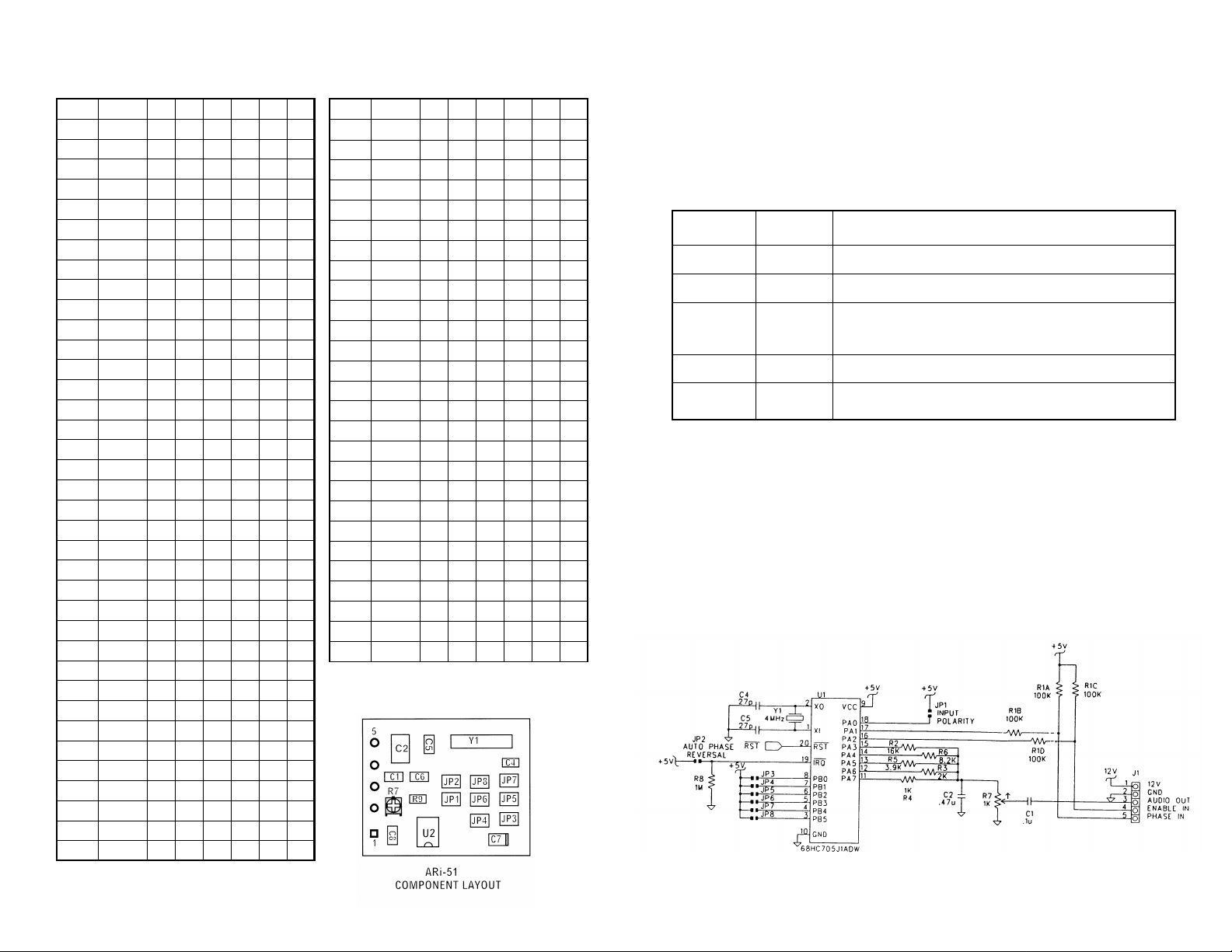
Table 1. Program Jumpers
Tone Number JP8 JP7 JP6 JP5 JP4 JP3
67.0 0
69.3 1 X
71.9 2 X
74.4 3 X X
77.0 4 X
79.7 5 X X
82.5 6 X X
85.4 7 X X X
88.5 8 X
91.5 9 X X
94.8 10 X X
97.4 11 X X X
100.0 12 X X
103.5 13 X X X
107.2 14 X X X
110.9 15 X X X X
114.8 16 X
118.8 17 X X
123.0 18 X X
127.3 19 X X X
131.8 20 X X
136.5 21 X X X
141.3 22 X X X
146.2 23 X X X X
151.4 24 X X
156.7 25 X X X
159.8 26 X X X
162.2 27 X X X X
165.5 28 X X X
167.9 29 X X X X
171.3 30 X X X X
173.8 31 X X X X X
177.3 32 X
179.9 33 X X
183.5 34 X X
186.2 35 X X X
189.9 36 X X
Tone Number JP8 JP7 JP6 JP5 JP4 JP3
192.8 37 X X X
196.6 38 X X X
199.5 39 X X X X
203.5 40 X X
206.5 41 X X X
210.7 42 X X X
218.1 43 X X X X
225.7 44 X X X
229.1 45 X X X X
233.6 46 X X X X
241.8 47 X X X X X
250.3 48 X X
254.1 49 X X X
50 X X X
51 X X X X
52 X X X
53 X X X X
54 X X X X
55 X X X X X
56 X X X
57 X X X X
58 X X X X
59 X X X X X
60 X X X X
61 X X X X X
62 X X X X X
63 X X X X X X
Figure 1. PCB Layout
Wiring Interface
This sub miniature module will easily fit in almost all popular mobile and portable
radios. Most radio manufacturers provide recommended hook up points in their radios
for CTCSS. Where possible follow the manufacturers instructions. See Table 2 for
wiring details.
Table 2. Wiring Diagram
Pin # Color Description
Pin 1 Red
Pin 2 Black
Pin 3 Orange
Pin 4 Light Green
Pin 5 Blue/White
Mounting Details
Place the provided heatshrink tubing around the ARi-51 module and shrink the tubing
with a heat gun (preferred). Mount the encoder to a suitable location in the radio,
preferably away from high RF and sensitive receiving stages, with the provided
double-sided tape. Note: Do not overheat the encoder while using a heat gun. You
will melt the solder and the SMD components on the circuit board will become
dislodged, causing failure of the encoder, and voiding of the warranty.
Figure 2. Circuit Diagram ARi-51
12 V: Connect to the radio’s switched transmit voltage source.
Ground: Connect to the radio 0 volt point (ground).
Tone Out: Connect to a (transmit) audio point after the limiter/
clipper stage but before the radio’s modulator. Do not connect to the
radio’s microphone input as distortion will occur.
PTT In: Connect to microphone PTT switch.
Phase Reversal Input: This input can be used to activate Phase
Reversal (JP1 must be shorted).
 Loading...