

Page 1
XLS-12S & XLS-15S SUBWOOFERS
User Manual
Page 2

CERWIN-VEGA’S LIMITED WARRANTY
W
elcome to the family
First off, you have great taste in loudspeakers. At Cerwin-Vega!,
deep bass and great highs are a way of life. Nice to know there
are a few people out there who share our passion for music. You’ll
be glad to know that this company has been in business since
1953. And we consider you to be the newest member of the family.
We hope your speakers give you years of enjoyment. Of course,
in the event of a problem, make sure you familiarize yourself with
this warranty. We like to think that while you’re sitting in front of
your speakers, we’re standing behind them. And now a few choice
words from our lawyer. (Hey, every family has one).
Who’s
Cerwin-Vega’s Limited Warranty on residential speakers extends
only to the original purchaser as evidenced by the original
Bill of Sale and only to the residential speakers purchased from
authorized Cerwin-Vega! dealers.
Ten words of advice:
W
Cerwin-Vega! warrants that all new residential speakers shall
be free from defects in material and workmanship, under normal
and proper use. Cerwin-Vega! agrees to repair or replace (at our
option) all such defective parts at no charge for labor or materials.
W
This Limited Warranty does not apply to defective equipment
that: has been altered or repaired by other than factory approved
procedures; has been subjected to negligence, misuse or
accident; has been damaged by improper line voltage; had its
serial number or any part of it altered, defaced, or removed; has
been used for other than home entertainment purposes; or has
been used in a way that is contrary to Cerwin-Vega’s written
instructions.
Except as provided by statute, this Limited Warranty does not
cover losses, consequential or otherwise, resulting from the
improper use of, or inability to operate, any Cerwin-Vega! product.
hoW
Cerwin-Vega’s Limited Warranty extends for a period of (5)
years for all system speaker components , two (2) years for
all associated electronics components, including amplifier and
controller devices, and one (1) year for speaker stands and wall
mount brackets, from the date of purchase as shown on the
original Bill of Sale.
The warranty period will be extended if the warranty repairs
have not been performed due to delays caused by Cerwin-Vega!
or a representative of Cerwin-Vega!, or if the warranty repairs
did not remedy the defect and the original purchaser notifies
Cerwin-Vega! or the original dealer or an Authorized Cerwin-Vega!
Service Center of the failure of the repairs within 30 days after they
were completed.
covered by this Warranty
Retain the original bill of sale, in a safe place!
hat’s covered by this Warranty
hat’s not covered by this Warranty
long does the Warranty extend
!
?
?
?
?
hoW do
In order to obtain warranty service, contact your original dealer or
distributor, or an Authorized Cerwin-Vega! Service Center. If, for
some reason, you have trouble locating a service representative,
contact Cerwin-Vega’s Customer Service Department for
assistance:
Cerwin-Vega! Customer Service Dept.
772 S. Military Trail
Deerfield Beach, FL 33442
In some cases, the Customer Service Department can
solve a service problem without any return of equipment,
thereby avoiding transit delays. For more information visit
http://www.cerwin-vega.com/service_support.php
W
If the Customer Service Department determines that the
equipment must be returned to Cerwin-Vega! for service, a
Return Authorization will be issued by mail, and the defective
merchandise may be shipped directly to the above address freight
prepaid, along with a copy of both the Return Authorization and the
original Bill of Sale.
The product will be replaced or repaired (at our option) and
returned to the original purchaser. Only the return postage will
be paid by Cerwin-Vega! Cerwin-Vega! will not be responsible for
damage occurring in shipment from the original purchaser or due
to improper packing materials. Remember to pack all equipment
carefully and in the original carton if possible. Additional charges
may be added if new packing materials are required for return
shipment.
W
The exercise of any of the provisions under the Limited Warranty
does not affect the protections or remedies of the original
purchaser under other laws. If you have additional questions
about service, write or call the Customer Service Department.
This Limited Warranty applies to all residential speakers, and
supersedes all previous warranty statements. Cerwin-Vega!
reserves the right to make changes in product design and
specifications at any time.
EXCEPT AS PROVIDED HEREIN AND BY APPLICABLE LAW,
CERWIN-VEGA! MAKES NO ADDITIONAL REPRESENTATION
OR WARRANTY OF ANY NATURE WHATSOEVER, EXPRESSED
OR IMPLIED, AS TO THE EQUIPMENT, INCLUDING BUT
NOT LIMITED TO, THE MERCHANTABILITY, FITNESS
FOR A PARTICULAR PURPOSE, DESIGN CONDITION OR
WORKMANSHIP OF THE EQUIPMENT, OR THE QUALITY
OF THE MATERIAL INCLUDED THEREIN, THIS LIMITED
WARRANTY CONSTITUTES THE SOLE AND ENTIRE
AGREEMENT BETWEEN CERWIN-VEGA! AND THE ORIGINAL
PURCHASER.
you get Warranty service
hat if the product must be returned
Save your original packing materials!
hat are other remedies under the laW
?
?
?
ii
Page 3
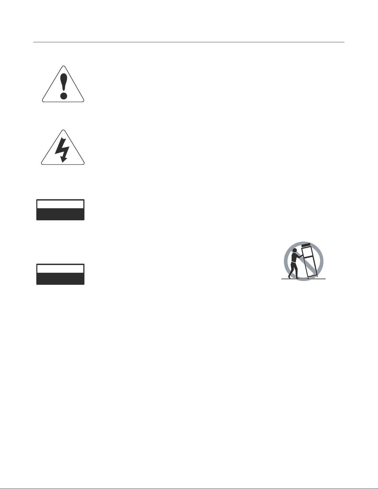
IMPORTANT SYMBOLS AND SAFETY INSTRUCTIONS
e
xplanation of graphic symbols
i
mportant safety instructions
CAUTION
RISK OF ELECTRIC SHOCK
DO NOT OPEN!
DO NOT EXPOSE
TO RAIN OR MOISTURE!
The exclamation point within an
equilateral triangle is intended to
alert the users to the presence of
important operating and maintenance
(servicing) instructions in the literature
accompanying the product.
The lightning flash with the arrowhead
symbol, within an equilateral triangle,
is to alert the user to the presence of
insulated “dangerous voltage” within
the products enclosure that may be of
sufficient magnitude to constitute a risk
of electric shock to humans.
CAUTION: TO REDUCE THE RISK
OF ELECTRONIC SHOCK - DO NOT
REMOVE COVER.
NO USER SERVICEABLE PARTS
INSIDE. REFER SERVICING TO
QUALIFIED PERSONNEL.
1. Read and keep these instructions.
2. Heed all warnings and follow instructions
3. Do not use this apparatus near water.
4. Clean only with a dry cloth.
5. Do not block any ventilation openings.
6. Do not install near any heat sources such as radiators, heat
registers, stoves, or other apparatus that produce heat.
7. Do not defeat the safety purpose of the polarized or grounding
type plug. A polarized plug has two blades with one wider
than the other. A grounding-type has two blades and a third
grounding prong. The wide blade or the third prong is provided
for your safety. If the provided plug does not fit your outlet,
consult a electrician for replacement of the obsolete outlet.
8. Protect the power cord from being pinched, particularly at
plugs, convenience receptacles, and the point where they exit.
9. Only use attachments / accessories specified by the
manufacturer.
10. Use only with a cart, stand, bracket, or table specified by the
manufacturer or sold with the apparatus. When a cart is used,
use caution when moving the cart /apparatus combination to
avoid injury from tip-over.
CAUTION
RISK OF ELECTRIC SHOCK
DO NOT OPEN!
DO NOT EXPOSE
TO RAIN OR MOISTURE!
ATTENTION: POUR EVITER LES
RISQUES DE CHOC ELECTRIQUE,
NE PAS ENLEVER LE COUVERCLE
AUCUN ENTRETIEN DE PIECES
INTERIEURES PAR L’USAGER
CONFIER L’ENTRETIEN AU
PERSONNEL QUALFIE. AVIS: POUR
EVITER LES RISQUES D’INCENDIE
OU D’ELECTROCUTION, N’EXPOSEZ
PAS CET ARTICLE A LA PLUIE OU A
L’HUMIDITE.
11. Unplug this apparatus during lightning storms or when unused
for long periods of time.
12. Refer all servicing to qualified service personnel. Servicing is
required when a apparatus has been damaged in any way,
such as power-cord or plug is damaged, liquid has been spilled,
or objects have fallen into the apparatus, the apparatus has
been exposed to rain or moisture, does not operate normally,
or has been dropped.
13. To reduce the risk of fire or electric shock, do not expose this
apparatus to rain or moisture.
14. The apparatus shall be connected to a main socket outlet with
a protective connection.
a) Mains plug is used as the disconnect device. It shall remain
readily operable and should not be obstructed during intended
use.
b) The apparatus shall not be exposed to dripping or splashing
and that no objects filled with liquids, such as vases, shall be
placed near/on the apparatus.
iii
Page 4

CONTENTS
1. Introduction ......................................................................................................................................................................................... 1
2. Subwoofer Installation ....................................................................................................................................................................... 1
2.1. Prior to Installation ..................................................................................................................................................................... 1
2.2. Installation ................................................................................................................................................................................... 1
2.3. Control Descriptions ................................................................................................................................................................... 1
2.4. Placement ................................................................................................................................................................................... 2
3. Connecting your Subwoofer ............................................................................................................................................................. 3
3.1. Line Level Connections ............................................................................................................................................................. 3
3.2. Speaker Level Connections ...................................................................................................................................................... 3
4. Troubleshooting ................................................................................................................................................................................. 4
5. Specifications ...................................................................................................................................................................................... 4
1. introduction
This manual covers operation information for the Cerwin-Vega’s XLS-12S & XLS-15S Subwoofers. Illustrations of control locations and
hook-up wiring may differ in physical appearance and location than those shown on the actual product you own. However, the operation
information is still the same.
2. subWoofer installation
2.1 prior to installation
Carefully unpack your subwoofer and save the box and all of the packing material. At some point, you may need to transport, ship, or move
your subwoofer. Before continuing with the installation, please make sure the subwoofer is unplugged and the power switch is turned “OFF.”
Warning: Severe damage may result from improperly selected voltage.
Refer to qualified service personnel to select voltage.
2.2 installation
Please read the following to determine which installation procedure is best for your audio/video system. For additional hook-up connections,
you may want to refer to your A/V receiver, processor, preamplifier, or amplifier’s manual.
Note: Read carefully the “Important Symbols and Safety Instructions” page before starting the installation.
2.3 CONTROL DESCRIPTIONS
The following controls are located on the XLS subwoofer’s rear panel (Figure 1), page 2.
Attention! The Cerwin-Vega’s XLS Subwoofers have LFE, Line Level, and SPEAKER-LEVEL input connections. Please choose one option
only for hook-up. Do not hook up more than one option!
1. LFE INPUT: Mono “low frequency effects” connection. Use this input if receiver/preamp/processor has a dedicated LFE or subwoofer
OUT. Refer to the owner’s manual provided by your receiver/preamp/processor manufacturer. Set receiver’s crossover to 150 Hz.
2. LINE LEVEL INPUT: Stereo low-level input to subwoofer. Connect to “LINE-OUT”, “MAIN-OUT or PREAMP-OUT,” of your receiver/
preamp/processor using a dual RCA patchcord (not supplied). Refer to the owner’s manual provided by your receiver/preamp/processor
manufacturer. Set receiver’s crossover to 150 Hz.
3. SPEAKER LEVEL INPUT: Stereo high-level inputs to subwoofer. Use these terminals when line level connections are not available from
A/V receiver/preamp/processor. Connect to SPEAKER outputs on receiver using high-quality speaker wire (16-gauge or heavier). Set the
front left and right speaker settings to large or full range.
4. SPEAKER LEVEL OUTPUT: Audio loop of stereo high-level (SPEAKER LEVEL) inputs. Use to loop (continue) signal to speaker
connections to the left and right main speakers.
5. VOLUME CONTROL: Controls volume level of subwoofer. Use to balance the output of the subwoofer with the main speaker output.
6. CROSSOVER FREQUENCY: The crossover control allows you to adjust the upper limit of the subwoofer’s frequency response from 50 to
150 Hz. The subwoofer’s response will begin rolling off above the set frequency.
Note: Crossover control does not function when LFE input is used.
1
Page 5

2.3 CONTROL DESCRIPTIONS (CONT.)
Figure 1
7. PHASE: This switch allows you to compensate for having the subwoofer in a different location than the main speakers. This control allows
the signal to be delayed 180 degrees so the output of the subwoofer will blend in with the main speakers. Slide the PHASE switch to “180.”
At the listening position, listen to the mid bass output. If it sounds weak, set PHASE back to “0.”
8. POWER LED: Power indicator lamp. Glows green in “ON” mode if audio signal is present. Glows red in both “OFF” mode and “ON” mode
if receiving AC power, and if audio signal is not present after approximately 30 minutes.
9. POWER: Two-position power switch. In the “ON” mode, the subwoofer’s amplifier is automatically activated if an audio signal is present
and will automatically become inactive when there is no audio signal present after approximately 30 minutes. In the “OFF” mode, power is
shut off to the amplifier.
10. VOLTAGE SELECTION: XLS products have 120 V and 240 V capabilities and are shipped with voltage specific fuses:
(110 V – 120 V – T6.3AL / 220 V – 240 V – T3.15ALAC).
Warning: Severe damage may result from improperly selected voltage.
11. POWER CORD RECEPTACLE: Connect the IEC cord to this receptacle (supplied with the subwoofer). If the IEC cord does not fit in
your AC outlet, please purchase another AC cord from your audio dealer or electrical supply store.
12. REPLACEABLE FUSE: Protects system from overload.
Refer to qualified service personnel to change the fuse.
Refer to qualified service personnel to select voltage.
2.4 placement
Your XLS Series Powered Subwoofer produces low frequencies which are omnidirectional. As a result, placement requirements for your
subwoofer are flexible and subject to your listening room’s acoustic characteristics. To determine the best position for your subwoofer, start
by positioning it along the same wall, or plane, as your main speakers. Experiment with various locations until you find the location that
sounds best to you.
Note: Typically, your powered subwoofer will sound best when placed between the front main satellites.
Caution! Do not place heavy objects of any type, such as televisions on top of any Cerwin-Vega! speaker unless otherwise recommended
by Cerwin-Vega! XLS Series speakers are for residential applications only.
* Refer to the owner’s manual provided by your main speaker manufacturer to determine your main speaker’s low-end frequency response.
2
Page 6

3. CONNECTING YOUR SUBWOOFER
3.1 line level connections
Connect the LFE Output of an A/V receiver to the LFE Input (1) of the XLS subwoofer, or connect the left and right line level outputs of an AV
receiver to the left and right Line Level Inputs (2) of the XLS subwoofer. (Figure 2). See your A/V receiver’s bass management instructions
for proper integration into your system.
Figure 2
3.2 speaKer level connections
Connect the left and right speaker-level outputs of an A/V receiver to the Left and Right Speaker-Level Inputs (3) of the XLS subwoofer.
Then connect the Left and Right Speaker Level Outputs (4) of the XLS subwoofer to the left and right speakers on your system. Remember
to maintain left to left, right to right, (+) to (+) and (-) to (-) connections. (Figure 3).
Figure 3
Note: The signal coming from Speaker Level Inputs (3) through the Speaker Level Outputs (4) is high-pass filtered at 100 Hz*. This removes
the bass below 100 Hz from your left and right speakers. The subwoofer is used to reproduce the frequencies below 100 Hz*.
*The passive high pass filter used in the speaker level output is dependent on your speaker impedance for the actual crossover frequency.
Because of this, we recommend that you start with a crossover frequency (6) setting of 100 Hz, and then adjust Volume (5) and Phase
(7). If there is too little midbass, turn the crossover frequency up (6). If there is too much midbass, turn the crossover frequency down (6).
Experimentation and listening are the keys to proper subwoofer integration.
3
Page 7

4. TROUBLESHOOTING
s
ymptoms
Bass sounds distorted
Distortion with volume control near
minimum
c
auses
Amplifier is at maximum output
Receiver tone controls are set too high
Defective receiver or preamplifier, or
shorted speaker wires
s
olutions
Lower volume or receiver level control
Set bass flat; use tone controls sparingly
Repair defective receiver, preamplifier or
replace speaker wires
Distortion on music peaks or sound
effects
Buzz, hum, or crackle when connecting
wires
Buzz or hum when system is On
No sound after listening at high-levels
5. SPECIFICATIONS
Dynamic soundtrack (e.g., explosions)
Connecting wires with power on causes
transient signal spikes
Grounding problem or ground loop
Amplifier’s thermal protection has been
temporarily activated
Turn down volume control to lower overall
range
Connect wires only when system power
is Off
Check receiver or preamplifier manual for
help in eliminating a ground loop
Lower subwoofer volume and allow
amplifier to cool down; sound should
resume automatically
XLS-12S XLS-15S
Speaker Type 12” Ported Design Subwoofer 15” Ported Design Subwoofer
±3 dB 43 Hz to 300 Hz LFE in,
Frequency Response
Frequency Range (-10 dB) 1: 28 Hz – 150 Hz (-10 dB) 1: 25 Hz – 150 Hz
Amplifier Power 250 W RMS 250 W RMS
Dimensions
(HxWxD)
Net Weight 48 lbs / 21.7 kg 68 lbs / 30.8 kg
LF Driver 12” Paper cone foam half roll cast
Input Connectors L&R + LFE RCA, and speaker
44 Hz to 180 Hz left or right in
±10 dB 38 Hz to 350 Hz LFE in,
39 Hz to 225 Hz left or right in
18.2” x 13.8” x 20.5”
460 mm x 350 mm x 520 mm
frame woofers
level barrier strips
±3 dB 40 Hz to 300 Hz LFE in,
41 Hz to 190 Hz left or right in
±10 dB 34.5 Hz to 430 Hz LFE in,
35.5 Hz to 225 Hz left or right in
24.1” x 17” x 22.9”
610 mm x 430 mm x 580 mm
15” Paper cone foam half roll cast
frame woofers
L&R + LFE RCA, and speaker
level barrier strips
4
Page 8

772 S. Military Trail • Deerfield Beach, FL 33442
www.cerwin-vega.com
LITH00011 8/14/2009
 Loading...