

Page 1

Operation and Installation Manual
CERWIN-VEGA!
MOBILE AUDIO
POWER AMPLIFIER
XL 150.2
XL 300.2
XL 300.4
CV XL150_300.2.4 Manual 5/21/04 4:40 PM Page 1
Page 2

CERWIN-VEGA! XL150.2 | XL300.2 | XL300.4 POWER SYSTEM AMPLIFIERS
This section lists Mounting and Wiring
Precautions for installing Cerwin-Vega! XL Series
amplifiers. Combined with the experience of a
professional installer, these safeguards provide
enough detail to successfully complete an
installation. If you do not have the necessary
skills, do not install the amplifier yourself.
Instead, see your authorized Cerwin-Vega! dealer
for installation recommendations.
MOUNTING PRECAUTIONS
Although Cerwin-Vega! EXL Series amplifiers
incorporate heat sinks and protection circuits,
mounting the amplifier in a tight space without any
air movement can still damage internal circuitry
over time. Choose a site that provides adequate
ventilation around the amplifier. For easy system
set-up, mount the amplifier so the front panel
controls will be accessible after installation. In
addition, observe the following precautions:
1. For the most efficient cooling, mount the
amplifier so cool air runs along the length of
the fins rather than across them. Remember,
any moving air will dissipate heat.
2. Mount the amplifier on a rigid surface.Avoid
mounting to subwoofer enclosures or areas
prone to vibration. Do not install the
amplifier on plastic or other combustible
materials.
3. Prior to drilling, make sure proposed
mounting holes will not cut into the fuel
tank, fuel lines,brake lines (under chassis) or
electrical wiring.
WIRING PRECAUTIONS
Read all wiring precautions. If you are not sure of
the connections, contact your authorized CerwinVega! dealer.
1. Before installation, make sure the source
unit Power switch is in the OFF position.
2. Disconnect the negative (-) lead of the battery
before making any power connections.
3. When making connections, be sure that
each connection is clean and secure.
Insulate final connections with electrical
INTRODUCTION
Thank you for purchasing a Cerwin-Vega! car
audio amplifier. This power amplifier has been
designed to provide high quality performance
with a minimum of maintenance. However, it’s
performance will only be as good as the care
and quality of components with which it is
installed. We therefore advise that you read
these instructions very carefully to familiarize
yourself with the product and it’s features.
Before installing the power amplifier please read
this instruction manual carefully. The instructions
for mounting and connecting the unit have to be
followed precisely. If necessary, a service center
should be consulted.
All connections for DC power, signal input and
speaker outputs can be carried out easily and
safely by way of RCA and screw terminals.
INSTALLATION INSTRUCTIONS
CV XL150_300.2.4 Manual 5/21/04 4:40 PM Page 2
Page 3
OPERATION AND INSTALLATION MANUAL
1
•2 & 4 Channel power amplifier
•4 Ohm stable in bridge mode
•2 Ohm stable in stereo mode
• Low&High level input
• X-over control
• Crossover Switch
• Gain (input level) controls
• Bass boost control
•Thermal protection
• Short circuit protection
• Remote Turn-on
• Protection LED indicator
•Power on LED indicator
FEATURES
tape or shrink tubing. Failure to do so may
damage your equipment.
4. A secure clean ground connection is critical
to the performance of your Cerwin-Vega!
amplifier. Use the shortest ground wire
possible and securely connect to the car
chassis to minimize resistance and avoid
noise problems.
5. Add an external fuse on the amplifier’s
positive (+) power lead and connect it as
close as possible to the vehicle’s (+) battery
terminal. Use a rating that equals the total
current consumption at full output of all
amplifiers in the system. Adding an external
fuse will protect the electrical system from
short circuits that can cause a fire.
CV XL150_300.2.4 Manual 5/21/04 4:40 PM Page 1
Page 4

CERWIN-VEGA! XL150.2 | XL300.2 | XL300.4 POWER SYSTEM AMPLIFIERS
2
If the fuse blows, check the power connection and
replace the fuse. If the fuse blows again after
replacement, there may be an internal malfunction.
In this case, consult your dealer.
Warning
Use the specified amperage fuse. Use of a higher
amperage fuse may cause serious damage.
Protection Circuit
This amplifier is provided with a protection circuit
which operates when:
- the unit is overheated or when the speaker
terminals are short circuited.
•This unit is designed for negative ground 12V
DC operation only.
• Use speakers with an impedance of 2 or 4 Ohms
• Avoid installing the unit where:
- It would be subject to high temperatures, such as
from direct sunlight or hot air from the heater.
- It would be exposed to rain or moisture.
- It would be subject to dust or dirt.
• If your car is parked in direct sunlight and there
is a considerable rise in temperature inside the
car, allow the unit to cool off before operation.
• When installing the unit horizontally, be sure not
to cover the heatsink fins with the floor carpet.
• If this unit is placed too close to the car radio,
an interference may occur. In this case,
separate the amplifier from the car radio.
•This power amplifier employs a protection
circuit to protect the transistors and speakers if
the amplifier malfunctions. Do not attempt to
test the protection circuits by covering the
heatsink or connecting improper loads.
• Do not use the unit with a weak auto battery as
its optimum performance depends on a normal
battery supply voltage.
•For safety reasons, keep the volume of your car
audio system moderate so that you can still
hear normal traffic sounds outside your car.
PRECAUTIONS
FUSE REPLACEMENT
CV XL150_300.2.4 Manual 5/21/04 4:40 PM Page 2
Page 5

OPERATION AND INSTALLATION MANUAL
3
POWER CONNECTION
•The battery terminal (BATT) must be connected
directly to the positive terminal of the vehicle
battery to provide an adequate voltage source
and minimize noise. Connecting the battery
terminal lead to any other point (such as the
fuse block) will reduce the power output and
may cause noise and distortion. Use only #12
gauge or thicker (smaller gauge #) wire for this
lead and connect it to the terminal of the
battery after all other wiring is completed. This
connection must be fused at the battery
terminal.
GROUND CONNECTION
•The ground terminal (GND) connection is also
critical to the correct operation of the amplifier.
Use a wire of the same gauge as the power
connection (#12 or thicker) and connect it
between the ground terminal (GND) of the
amplifier and a metal part of the vehicle close
to the mounting location. This wire should be
as short as possible and any paint or rust at the
grounding point should be scraped away to
provide a clean metal surface to which the end
of the ground wire can be screwed or bolted.
REMOTE TURN-ON CONNECTION
•The amplifier is turned on by applying +12V to
the remote turn-on terminal (REM). The wire
lead to this terminal should be connected to
the “Auto-Antenna” lead from the car stereo
which will provide the +12V only when the car
stereo is turned on . If the car stereo does not
provide an “Auto-Antenna” lead, the remote
turn-on lead may be wired to an “Accessory”
or “Radio” terminal in the car’s fuse block.This
will turn the amplifier on and off with the
ignition key, regardless of whether the car
stereo is on or off. The remote turn-on lead
does not carry large currents. So #20 gauge
wire may be used for this application.
SPEAKER CONNECTIONS
• Depending on the type and number of speakers
used with the amplifier wire them to the
speaker terminals as per the appropriate wiring
diagram. For most applications # 18 gauge wire
should be used for the speaker leads but in no
case thinner than #20 gauge. For leads is excess
of 10 feet #16 gauge is recommended. When
wiring the speakers,pay careful attention to the
polarity of the terminals on the speakers and
make certain they correspond to the polarity of
the corresponding terminals on the amplifier.
Do not ground any speaker leads to the chassis
of the vehicle. Please see your authorized
Cerwin-Vega! dealer for specific wire
recommendations.
INPUT CONNECTIONS
•This amplifier features both and high low-level
input capability. Use either the low-level or
high- level inputs, not both.
• If the car stereo does not provide low-level
outputs, the amplifier may be connected via the
speaker (high-level). Outputs from the stereo.
Wire the speaker leads from the car stereo to
the 5-pin adapter harness as shown in the
diagram (shielded cables is not required for this
application) and plug the connector into the
mating high level input connector on the
amplifier. Carefully splice and insulate all wire
connection.
CAUTION: Use either the low-level or the highlevel inputs on the amplifier. Do not use both
input levels at the same time.
WIRING INSTRUCTIONS
CV XL150_300.2.4 Manual 5/21/04 4:40 PM Page 3
Page 6

CERWIN-VEGA! XL150.2 | XL300.2 | XL300.4 POWER SYSTEM AMPLIFIERS
4
XL 150.2
XL 300.2
XL 300.4
INPUT WIRING DIAGRAM
CV XL150_300.2.4 Manual 5/21/04 4:40 PM Page 4
Page 7

OPERATION AND INSTALLATION MANUAL
5
XL 150.2
XL 300.2
XL 300.4
SPEAKER CONNECTIONS
CV XL150_300.2.4 Manual 5/21/04 4:40 PM Page 5
Page 8

CERWIN-VEGA! XL150.2 | XL300.2 | XL300.4 POWER SYSTEM AMPLIFIERS
6
XL 150.2
XL 300.2
XL 300.4
BRIDGED MODE
CV XL150_300.2.4 Manual 5/21/04 4:40 PM Page 6
Page 9

OPERATION AND INSTALLATION MANUAL
7
POWER CONNECTION LEADS
NOTES ON THE POWER SUPPLY
• Connect the +12V power input lead only after
all other leads have been connected.
• Be sure to connect the ground wire of the unit
securely to a metal part of the car.A lose connection
may cause a malfunction of the amplifier.
• REM: The unit is turned on by applying +12
Volts to this terminal. This terminal does not
draw heavy current like the tow Power
Terminals so a thinner connecting wire is
acceptable. Standard 18 GAUGE is fine and the
standard color is yellow. If the radio is
equipped with a Power Antenna control wire, it
can drive this terminal. If the Power Antenna
wire is already in use, you can still splice into it.
With this method, the unit will turn on
automatically with the radio.
• Use the power supply lead with a fuse attached
whose value is the same as original fuse.
• Place the fuse in the power supply lead
as close as possible to the car battery.
• During a full power operation, Maximum current
will run through the system. Therefore, make
sure that the leads to be connected to the +12V
and GND terminals of the unit respectively must
be larger than 10-Gauge (AWG.10).
CV XL150_300.2.4 Manual 5/21/04 4:40 PM Page 7
Page 10

CERWIN-VEGA! XL150.2 | XL300.2 | XL300.4 POWER SYSTEM AMPLIFIERS
8
After the amplifier has been installed and all
connections have been secured, turn the radio on
so that the amplifier is switched on automatically.
After a short power-on period, the amplifier
reaches its full performance.
Now turn up the volume slowly using the volume
control of the radio. If there is no sound or only
distortion, switch off the radio immediately. The
amplifier will also switch off automatically - and
check if all connections have been made correctly.
• POWER = LED POWER INDICATOR
After the orderly connection of the three power
terminals, the LED indicator shines green and
goes out with off.
• PROTECT = LED PROTECTION INDICATOR
This unit is equipped with an overload
protection. Immediately upon overloading (due
to short circuit or extreme temperature) the
overload protection is activated, and the red
LED indicator is illuminated. The amplifier is
now protected against damage. In case of
thermal protection a short cooling time must
be allowed after which the amplifier
automatically resumes operation.
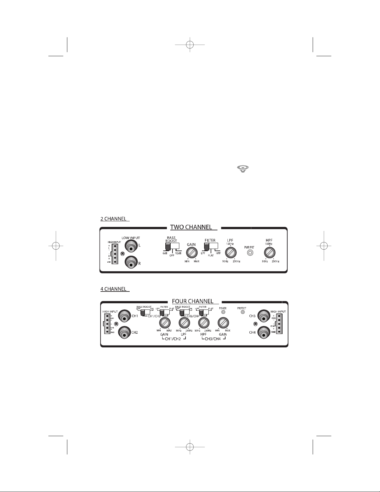
• GAIN = INPUT LEVEL CONTROL
The input level control allows the system to
work well within a wide range of output level.
Choose the adjustment in the way that you
achieve a sound most possibly without any
distortion. As a guideline the following
procedure is recommended: If you use several
amplifier, the adjustment has to be made for
each set separately tune in the volume of your
car radio to 2/3 of the maximum volume. Now
turn the gain control of the amplifier from “Min”
to “Max” direction until you can hear distortions.
Then turn the level control a little back to “Min”.
The gain control adjustment is finished now.
Attention!:
If you use 2 Ohm speakers in stereo
mode. Tri-mode or 4 Ohm speakers in bridge mode
and the overload protection is triggered out, turn
the gain control to “Min” direction, until the
operation is free of trouble.
• LPF & HPF CONTROL
a. When the crossover control is in the LPF
position, this control becomes active allowing
your to select your crossover point. For
example: If you select 50Hz the amplifier will
operate below 50Hz.
b. When the crossover control is in the HPF
position, this control becomes active allowing
you to select your crossover point. For
example: If your select 50Hz the amplifier will
operate above 50Hz.
• CROSSOVER SWITCH
Flat: Full range frequency
Low pass:
the lower frequency under setting
point can be pass.
High pass:
the higher frequency above setting
point can be pass.
•BASS BOOST CONTROLS
Boosts bass frequencies
OPERATION
CV XL150_300.2.4 Manual 5/21/04 4:40 PM Page 8
Page 11

OPERATION AND INSTALLATION MANUAL
9
• NO FUNCTION:
The connection cable is not connected
correctly (=terminal +12V/GND/REM). Ensure
that all connections and mechanical contact
are firmly in place. The fuse is defective-pay
attention to the correct value of a new fuse!
• NO SOUND:
Speaker cable or speaker plug are not
connected correctly.
• NO SOUND / RED LED
PROTECTION ILLUMINATES:
The plus and minus wires of the speaker
cable have contact, thus eliminate the short
circuit. If you use a 2 Ohm speaker in stereo
mode, a 4 Ohm speaker in bridge mode or
tri-mode and the set is overloaded, then
turn the gain control to “min” until the
operation is free of trouble.
•POOR SOUND QUALITY (DISTORTIONS):
The speakers are overloaded, therefore turn
down the volume level and check the
volume control positions.
• NO STEREO SOUND AND A WEAK BASS:
One or more speaker connections ( (+) and
(-) are reversed) are wired out of phase.
• GND(-) = GROUND CONNECTION
Connect the GND terminal to the chassis
ground of your car and take care of best
electrical and mechanical contact. In doing
so, drill a hole in to the car chassis near the
amplifier then remove color, dirt or any other
substance from the ground point . After that
fasten the cable end with added ring
terminal by using a screw. Ensure that the
ground connection is as short as possible and
that the cable diameter is sufficient (min
4mm”). Route the ground cables from the
radio and all other equipment parts. like
equalizer. active crossover network or other
amplifiers, to the same ground point.
• +12V = POWER SUPPLY
Connect the BATT terminal to the positive
pole of the battery with a lead cable and add
a fuse into the power cable in a distance of
not more then 12” from the battery.
• REM(ON/OFF) = REMOTE CONTROL
Connect the REM terminal to the automatic
antenna connector of your car radio. Now
when turning on and off your car radio. the
amplifier automatically switches ON and OFF.
• FUSE
The amplifier is equipped with a plug-in auto
fuse protecting the set against fault
conditions. Do not use a fuse with a higher
value and never bridge the fuse over, as this
may void the warranty.
OPERATION(cont.)
HOW TO PROCEED IN CASE OF FAULTS
CV XL150_300.2.4 Manual 5/21/04 4:40 PM Page 9
Page 12

CERWIN-VEGA! XL150.2 | XL300.2 | XL300.4 POWER SYSTEM AMPLIFIERS
10
INTERFERENCE
All cables are sources of interference. The power
cable and RCA audio cable are very prone to
interference; the remote cables are less prone.
There is often interference caused by the
generator (piping), ignition (cracking) or other car
electronic parts. Most of these problems can be
eliminated with correct and careful cable
installation. These are the following guidelines:
• Use only a quality audio cable for the wiring
between “low level in” of the amplifier and
RCA or DIN output of the radio.
• Lay the signal, speaker and power cables
separately with enough distance from another
and also from each other car cable. If not
possible, you can lay the circuit and ground
cable together with the serial cables.Audio and
speaker cable should be as far away from these
as possible. The REM cable to the automatic
antenna output of the radio can be laid
together with the signal cables.
• Avoid ground loops by laying the ground
wiring of all components to a center point. You
can find the best central point in measuring the
voltage directly at the battery and comparing
this voltage value with the chosen ground
point and the (+) terminal of the amplifier.
With the amplifier playing, if there is little or no
voltage diference at the amplifier input from
the battery, then you have found a good
location. You should measure with the ignition
being switched on as well as the (rear window
heating and light).
• If there are pickups from external electrical
sources into the speaker cables,divide the core
leads and twist them together.
• If there are noises from the car electronics, add
an interference suppression choke into the
power wiring.
• If there are humming noises, use thicker ground
cables or add further ground cables to the chassis.
•To reduce contact resistance and loose
contacts, please tie the cable ends or use multi
core cable ends, spade terminals or others.
• In the event that these steps are unsuccesful,
the use of a ground loop isolator may solve the
problem.
XL150.2 XL300.2 XL300.4
Frequency Response 10Hz - 60kHz, +0db -3 dB 10Hz - 60kHz, +0db -3 dB 10Hz - 60kHz, +0db -3 dB
Signal Noise Ratio, 4 ohm ref. >85 dB >85 dB >85 dB
THD, 4 ohm, - typical 0.05% 0.05% 0.05%
Input Sensitivity Low Level 250mV ~ >4V 250mV ~ >4V 250mV ~ >4V
4 Ohm Power output 2 x 50W @ 0.05% THD typical 2 x 10⁵W @ 0.05% THD typical 4 x 50W @ 0.05% THD typical
2 Ohm Power output 2 x 75W @ 0.05% THD typical 2 x 150W @ 0.05% THD typical 4 x 75W @ 0.05% THD typical
4 Ohm Bridged Power 1 x 150W @ 0.05% THD typical 1 x 300W @ 0.05% THD typical 2 x 150W @ 0.05% THD typical
Dimensions 2.25" H X 10.5" W X 11" L 2.25" H X 10.5" W X 13.25" L 2.25" H X 10.5" W X 13.25" L
PRODUCT SPECS
CV XL150_300.2.4 Manual 5/21/04 4:40 PM Page 10
Page 13

NOTES
11
CV XL150_300.2.4 Manual 5/21/04 4:40 PM Page 11
Page 14

9340 De Soto Ave., Chatsworth, CA 91311
Phone: 1-805-584-9332 • Fax: 1-805-583-0865 • Email: info@cerwin-vega.com
CV XL150_300.2.4 Manual 5/21/04 4:40 PM Page 12
 Loading...