

Page 1
Page 2

IT
SERIES
SUBWOOFERS
Attention!
PLEASE READ ALL WARNINGS FOUND IN THIS MANUAL.
THIS
INFORMATION IS HIGHLIGHTED IN BOLD ITALIC TYPE AND IS INCLUDED
TO INFORM YOU OF THE POTENTIAL FOR PERSONAL INJURY OR
DAMAGE TO PROPERTY.
Hearing Damage
CONTINUOUS, EXCESSIVE EXPOSURE TO SOUND PRESSURE
LEVELS IN EXCESS OF 85 dB CAN CAUSE A LOSS OF HEARING. CERWIN-
VEGA IT SERIES COMPONENTS ARE CAPABLE OF PRODUC/NG SOUND
PRESSURE LEVELS GREATER THAN 85 dB.
Volume and Driver Awareness
USE OF INTENSE TECHNOLOGY SERIES SUBWOOFERS CAN IMPAIR
YOUR ABILITY TO HEAR NECESSARY TRAFFIC SOUNDS AND MAY
CONSTITUTE A HAZARD WHILE DRIVING. WE RECOMMEND USING LOW
VOLUME LEVELS WHEN DRIVING YOUR VEH/CLE.
CERWIN-VEGA ACCEPTS NO LIABILITY FOR HEARING LOSS,
BODlLY INJURY, OR PROPERTY DAMAGE AS A RESULT OF USE OR
MISUSE OF THlS PRODUCT.
Installation Warning
USE EXTREME CAUTION WHEN TIGHTENING MOUNTING SCREWS,
AS SCREW HEADS CAN CATCH ON THE SURROUND AND CAUSE
DELAMINATION OF THE SPEAKER ASSEMBLY.
Cerwin-Vega is constantly striving to maintain the highest consumer standards. As a result of these efforts, modifications may
be made from time to time to existing products without prior notice. Specifications and appearance may differ from those listed
or shown in this manual. Cerwin-Vega is a registered trademark of Cerwln-Vega, Inc Dacron and Nomex are registered
trademarks of E.I. Du I’ont De Nemours & Co., Inc.
i
Page 3

I T SERIES SUBWOOFERS
For nearly 50 years, Cerwin-Vega has set the standard for
subwoofer performance worldwide. Established in 1954, CerwinVega was designing subwoofers before most competitors’ engineers
were born. Cerwin-Vega’s goal is to reproduce and even improve the
live musical experience. To this end, we have pioneered a design
philosophy which combines high efficiency with high power
handling, resulting in performance unequaled in dynamic capability.
Dynamics are, first and last, fundamental to the very purpose of
sound reproduction:
“To provide the listener with the highest order
of artistic and subjective resemblance to the condition of a live
rendition.”
Intense TechnologyTkl (IT) competition subwoofers are
designed for optimum performance in small sealed enclosures with
low frequency accuracy without sacrificing output. Each IT
subwoofer utilizes new engineering concepts and technological
innovations such as:
Infused Kevlar and Crystalline Oxide Fiber Cone with
Polypropylene Coating: Extremely rigid and strong with
exceptionally fast transient performance for “tight” natural
sounding bass and low distortion even at high power levels.
Natural Butyl Rubber Surround: Outstanding linearity under
hard drive/high power applications. Long throw with minimum
cone “drift” results in wide dynamic range and low distortion.
Resists ultraviolet radiation.
Nomex’r”’ Spider Material: Vastly stronger than conventional
cloth. Resists tearing or warping under high power conditions
for improved long-term reliability.
Deep-Draw Diecast Frame: More rigid than stamped steel so
frame distortion and resonances are effectively eliminated. Nonmagnetic so all the magnetic energy is used to tightly control the
diaphragm for increased output with prolonged reliability. High
efficiency combines with excellent transient response and
acoustic definition.
Proprietary Integrated Dust Dome: Dust dome is designed as a
7
Page 4
IT
SERIES
SUBWOOFERS
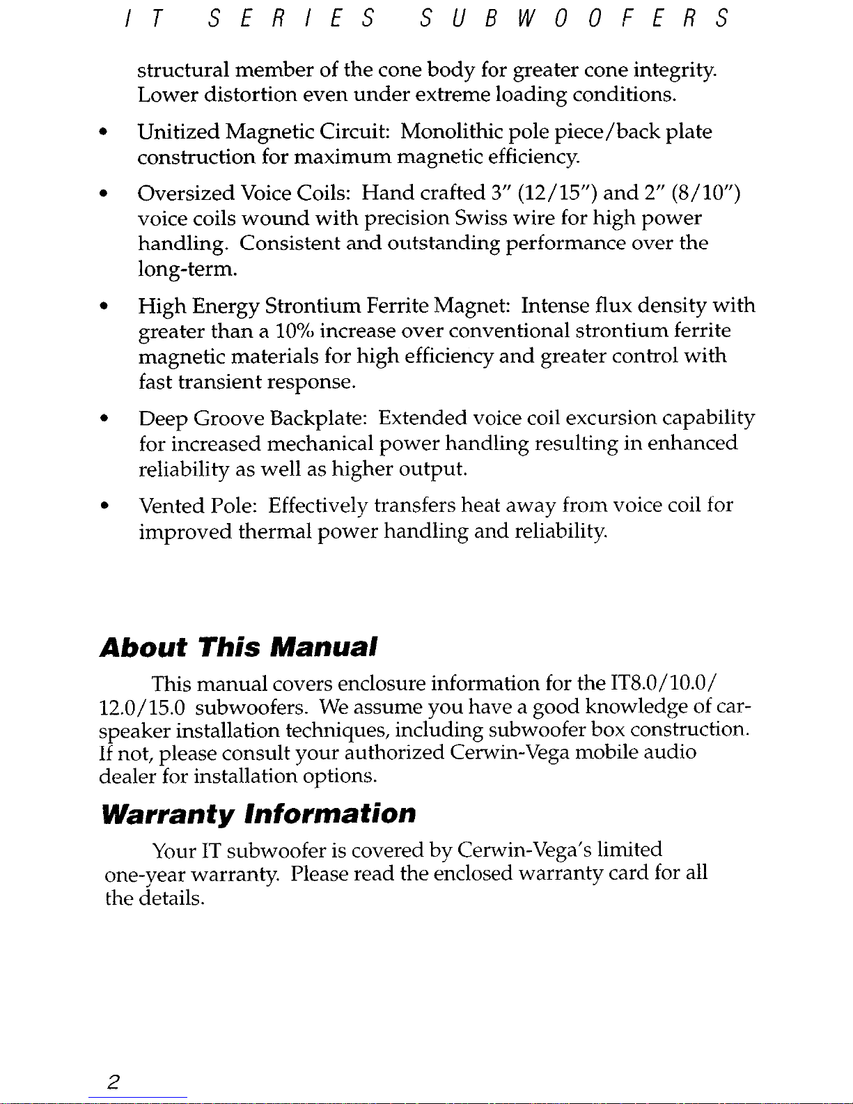
structural member of the cone body for greater cone integrity.
Lower distortion even under extreme loading conditions.
Unitized Magnetic Circuit: Monolithic pole piece/back plate
construction for maximum magnetic efficiency.
Oversized Voice Coils: Hand crafted 3” (12/15”) and 2” (S/lo”)
voice coils wound with precision Swiss wire for high power
handling. Consistent and outstanding performance over the
long-term.
High Energy Strontium Ferrite Magnet: Intense flux density with
greater than a 10% increase over conventional strontium ferrite
magnetic materials for high efficiency and greater control with
fast transient response.
Deep Groove Backplate: Extended voice coil excursion capability
for increased mechanical power handling resulting in enhanced
reliability as well as higher output.
Vented Pole: Effectively transfers heat away from voice coil for
improved thermal power handling and reliability.
About This Manual
This manual covers enclosure information for the ITS.O/lO.O/
12.0/15.0 subwoofers. We assume you have a good knowledge of carspeaker installation techniques, including subwoofer box construction.
If not, please consult your authorized Cerwin-Vega mobile audio
dealer for installation options.
Warranty information
Your IT subwoofer is covered by Cerwin-Vega’s limited
one-year warranty. Please read the enclosed warranty card for all
the details.
2
Page 5
IT
SERIES
SUBWOOFERS
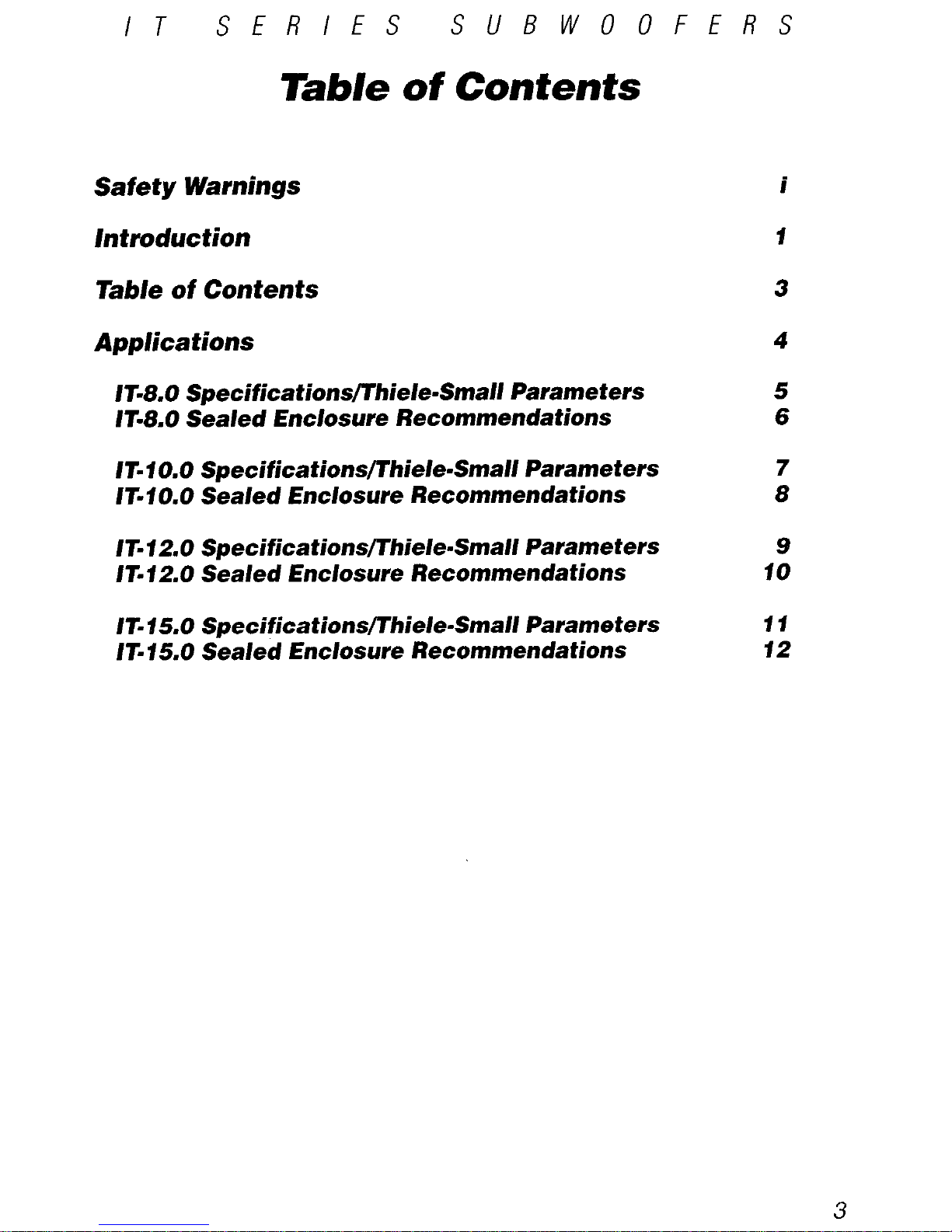
Table of Contents
Safety Warnings
introduction
Table of Contents
Applications
IF8.0 SpecificationslThiele-Small Parameters
5
W8.0 Sealed Enclosure Recommendations 6
IrIO. Specificationsflhiele-Small Parameters
7
IWO.0 Sealed Enclosure Recommendations 8
IT-120 Specificationsflhiel-Small Parameters
Irl2.0 Sealed Enclosure Recommendations
IT-15.0 SpecificationslThiele-Small Parameters
/T-15.0 Sealed Enclosure Recommendations
i
f
3
4
9
10
3
Page 6
I T
SERIES
SUBWOOFERS
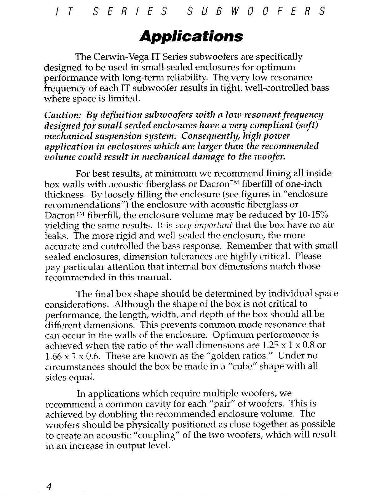
Applications
The Cerwin-Vega IT Series subwoofers are specifically
designed to be used in small sealed enclosures for optimum
performance with long-term reliability. Thevery low resonance
frequency of each IT subwoofer results in tight, well-controlled bass
where space is limited.
Caution: By definition subwoofers with a low resonantfrequency
designed for small sealed enclosures have a very compliant (soft)
mechanical suspension system. Consequently, high power
application ijz enclosures which are larger than the recommended
volume could result in mechanical damage to the woofer.
For best results, at minimum we recommend lining all inside
box walls with acoustic fiberglass or DacronT” fiberfill of one-inch
thickness. By loosely filling the enclosure (see figures in “enclosure
recommendations”) the enclosure with acoustic fiberglass or
DacronTM fiberfill, the enclosure volume may be reduced by lo-15943
yielding the same results. It is ZW~J importrrvzf that the box have no air
leaks. The more rigid and well-sealed the enclosure, the more
accurate and controlled the bass response. Remember that with small
sealed enclosures, dimension tolerances are highly critical. Please
pay particular attention
that
internal box dimensions match those
recommended in this manual.
The final box shape should be determined by individual space
considerations. Although the shape of the box is not critical to
performance, the length, width, and depth of the box should all be
different dimensions. This prevents common mode resonance that
can occur in the walls of the enclosure. Optimum performance is
achieved when the ratio of the wall dimensions are 1.25 x 1 x 0.8 or
1.66 x 1 x 0.6. These are known as the “golden ratios.” Under no
circumstances should the box be made in a “cube” shape with all
sides equal.
In applications which require multiple woofers, we
recommend a common cavity for each “pair” of woofers. This is
achieved by doubling the recommended enclosure volume. The
woofers should be physically positioned as close together as possible
to create an acoustic “coupling” of the two woofers, which will result
in an increase in output level.
4
Page 7
IT
SERIES
SUBWOOFERS
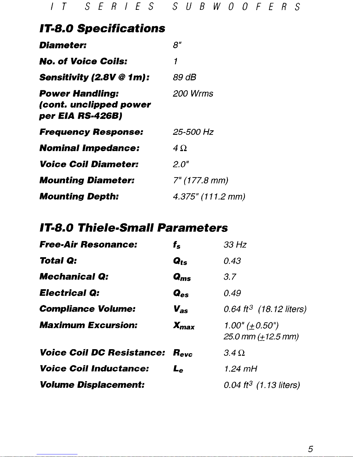
1F8.0 Specifications
Diameter:
No. of Voice Coils:
Sensitivity (2.8V 8 7m) :
Power Handling:
(cont. unclipped power
per HA RS-4266)
Frequency Response:
Nominal Impedance:
Voice Coil Diameter:
Mounting Diameter:
Mounting Depth:
8”
1
89 dB
200 Wrms
25-500 Hz
4fi
2.0”
7” (177.8 mm)
4.375” (111.2 mm)
1F8.0 Thiele-Small Parameters
Free-Air Resonance:
fs
Total 9:
Qts
Mechanical 9:
0
ms
Electrical 9:
Q
es
Compliance Volume:
V
as
Maximum Excursion:
X
max
Voice Coil DC Resistance: Rev=
Voice Coil Inductance:
Le
Volume Displacement:
33 Hz
0.43
3.7
0.49
0.64 ft3 (18.12 liters)
1.00” (*0.50’)
25.0 mm (2 12.5 mm)
3.4 R
1.24 mH
0.04 ft3 (1.13 liters)
Page 8

IT
SERIES
SUBWOOFERS
ma0 sealed F
rrequem=YRespovrse
Normalized Amplitude Response (d&SPUHz)
cln
6
0
-6
-12
-18
-24
-30
-36
I I I llllll
I I I
5HZ 10 50 100 500
Total Box Volume*:
0.4 ft3 (11.33 liters)
*Includes driver displacement of 0.04 ft3 (1.33 liters)
Page 9

IT
SERIES
SUBWOOFERS
IT-f 0.0 Specificat ions
Diameter:
No. of Voice Coils:
Sensitivity (2.W 8 lm):
Power Handling:
(cont. unclipped power
per E/A RS-4268)
Frequency Response:
Nominal Impedance;
Voice Coil Diameter:
Mounting Diameter:
Mounting Depth:
10”
1
91 dB
250 Wrms
20-500 Hz
4L2
2.0”
9” (228.6 mm)
5” (117.0 mm)
IT-f 0.0 Thiele-Small Parameters
Free-Air Resonance:
fs
Total Q:
Qts
Mechanical 9:
Q
ms
Electrical Q:
Q
es
Compliance Volume:
V
as
Maximum Excursion:
X
max
Voice Coil DC Resistance: Rev,
Voice Coil Inductance: Le
Volume Displacement:
26 Hz
0.59
4.0
0.69
1.95 ft3 (55.22 liters)
1.34”
(~0.67’)
34.Omm (*17.0mm)
3.4Q
1.4 mH
0.07 ft3 (1.98 liters)
7
Page 10

IT
SERIES
SUBWOOFERS
ITI10.0 Seaki F
-yRes;pourse
Normalized Amplltude Response (dB-SPL/Hz)
d0
6
n
-6
-12
-18
-24
30
-36
1 I
I I1
5w
10
60
100
500
Total Box Vo/ume*:
0.75 fts (2 1.24 liters)
*Includes driver displacement of 0.07 fP (1.98 liters)
IFiO.0 ‘cFilkf’ Sea/&d F
WY Resposrse
Normalized Amplitude
Response (dBSPL/Hr)
dB
6
0
6
-12
-18
Total Box Vo/ume*:
0.6 fp (17.00 liters)
*Includes driver displacement of 0.07 fP (1.98 liters)
8
Page 11

IT SERIES
SUBWOOFERS
lT= f 2.0 Specifications
Diameter:
12”
No. of Voice Coils:
1
Sensitivity (2.W 8 1~~7):
93 dB
Power Handing;
350 Wrms
(cont. unclipped power
per E/A RS-4266)
Frequency Response:
20-500 Hz
Nominal impedance:
4R
Voice Coil Diameter:
3.0”
Mounting Diameter:
11” (279.4 mm)
Mom ting Depth:
5.625” (142.9 mm)
T- 12.0 Thiele-Small Parameters
Free-Air Resonance:
f*
Total 9:
Qts
Mechanical 9:
Q
ms
EIectrical 9:
Q
es
Compliance Volume:
V
as
Maximum Excursion:
X
max
Voice Coil DC Resistance: Rev=
Voice Coil Inductance:
Le
Volume Displacement:
23 Hz
0.44
3.68
0.49
4.43 ft3 (125.44 liters)
1.0” (kO.5’)
25.0 mm b12.5 mm)
3.6R
2.09 mH
0.13 ft3 (3.68 liters)
9
Page 12

IT
SERIES SUBWOOFERS
dB
6
0
-6
-12
-18
-24
-30
36
5HZ
10
50 100
500
Total Box Vo/ume*:
7.00 ft3 (28.32 liters)
*Includes driver displacement of 0.13 ft3 (3.68 liters)
I7V 20 ccFiled’3ealed Fkxpency Response
LIB
6
0
b
12
18
24
30
-38
3n2
IO
100
300
Total Box Volume*:
0.8 fP (22.65 liters)
*Includes driver displacement of 0.13 fp (3.68 liters)
10
Page 13

IT
SERIES
SUBWOOFERS
lT45.0 Specifications
Diameter:
No. of Voice Coils:
Sensitivity (2.W 8 dm):
Power Handling:
(cont. unclipped power
per E/A RS-4266)
Frequency Response:
Nominal Impedance:
Voice Coil Diameter:
Mounting Diameter:
Mounting Depth:
15”
1
95 dB
400 Wrms
20-500 Hz
4Q
3.0”
73.75” (349.25 mm)
6.5 (165.15 mm)
IT-f 5.0 The/e-Small Parameters
Free-Air Resonance:
G
Total 9:
Qts
Mechanical 9:
Q
ms
Electrical Q:
Q
es
Compliance Volume:
V
as
Maximum Excursion:
X
max
Voice Coil DC Resistance: Rev=
Voice Coil Inductance:
Le
Volume Displacement:
23 Hz
0.60
3.50
0.73
9.18 ft3 (260.0 liters)
1.34” (20.67”)
34.0mm (*17.0mm)
3.30
2.0 mH
0.26 ft3 (7.36 liters)
Page 14

IT
SERIES SUBWOOFERS
IT-s.0 Seakf Fkquency Mspmse
Normalized Amplitude Response ~d6SPUHz~
I I
da
6
0
-6
-12
-18
-24
-30
-36
5HZ
10
50 100
500
Total Box Volume*: 2.75 ft3 (77.87 liters)
*Includes driver displacement of 0.26 ft3 (7.36 liters)
Normalized Amplitude Response (dBSPL/Hr~
CJB
6
0
.u
-12
1U
-24
-30
-36
5 Hz 10 50
100
500
Total Box Volume*: 2.25 ft3 (63.71 liters)
*Includes driver displacement of 0.26 fP (7.36 liters)
12
Page 15

Cerwin-Vega, 555 E. Easy Street, Simi Valley, CA 93065
Phone: 805-584-9332, Fax: 805-583-0865
Cerwin-Vega Canada, 1655 Feldspar Court #2, Pickering, Ontario Ll W 3R7
Phone: 905-837-7000, Fax: 905-837-0712
Cerwin-Vega Europe, Dali AlIe 1, DK-9610 Norager, Denmark
Phone: +45-98-551799, Fax: +45-98-551670
wwwzerwin-vega.com
TDMKL1160 0600
Page 16

IT
SERIES
SUBWOOFERS
Attention!
BY NATURE, BASS-REFLEX ENCLOSURES UNLOAD (THE BOX
BECOMES ACOUSTICALLY TRANSPARENT) AT f/2 OCTAVE BELOW THE
TUNlNG FREQUENCY.
THIS CAN RESULT IN OVER-EXCURSION OF THE
WOOFER CONE WH/CH CAN CAUSE MECHANICAL FAILURE.
TO PREVENT
OVER-EXCURSION WHEN USlNG AN IT SERIES WOOFER IN ITS
RECOMMENDED BASS-REFLEX ENCLOSURE, USE A SUBSONIC H/GHPASS FILTER WITH 25-35 HZ CUTOFF 0 12 DB PER OCTAVE.
Excursion Threshold
BassBox 6 Pro
in
0.63
0.55
5 Hz 10
I
50
100 500
Tuning Frequency
Example A: IT-72.0 SVC woofer cone excursion at 350 Watts RMS in
recommended ported enclosure without a subsonic filter.
BassBox 6 Pro
0.65
I !!!!I
I
/
0.47
0.39
I i iii
CL31
0.24
0.15
0.08
I I I Ill
I d I I11111
I
5 Hz
10
I
50
100 500
Tuning Frequency
Example B: IT- 12.0 SVC woofer cone excursion at 350 Watts RMS in
recommended ported enclosure with a subsonic filter.
CERWIN-VEGA
Page 17

IT
SERIES
SUBWOOFERS
IT-8.0 SVC/DVC Vented j.34
ft3
total
Enclosure Vol.: VBox =1.25
ft3
(net) + .04 ft3 + .05
ft3
IT-IO.0 SVC/DVC Vented 1.77 ft3 total
Enclosure Vol.: V
BOX=7.60ft3(net)+.07ft3+.70ft3
IT-72.0 SVC/DVC Vented 2.27
ft3
total
Enclosure Vol.: V
Box =2.00
ft3
(net) + .13 ft3 + .08 ft3
IT=i5.0 SVC/DVC Vented 3.93
ft3
total
Enclosure Vol.: V
Box =3.50
ft3
(net) + .26 ft3 + .17 ft3
V aox = vol. net + driver displacement + port displacement
W-8.0
Tuning Frequency:
35 Hz
Port Dimensions:
3.0” dia.
Port Area:
7.07 in2
Number of Ports:
I
Port Length:
10.50”
Port Displacement:
0.05 ft3
Total Box Volume:
1.34 ft3
Frequency Response
snz 10
50 100
- IT-8.0 svc - - - - IT-O.0 DVC
IT-10.0
35 Hz
4.0” dia.
12.57 in2
1
13.25”
0. IO fP
1.77 ft3
IT-12.0
35 Hz
4.0” dia.
12.57 in2
1
10.75”
0.08 ft3
2.21 ft3
mi5.0
35 Hz
4.0” dia.
25.73 in2
2
11.69”
0.17 ft3
3.93 ft3
- IT-IO.0 SVC - - - - IT-IO.0 DVC
- IT-150 SVC - - - - IT-15.0 DVC
TDJKL1163 ll/Oi
Page 18

CERWIN-VEGA!’
Tz Lm?
it
Z,Lqx
Page 19

WELCOME TO THE FAMILY!
First off. you have great taste ill Iouclq)eukt~r~. At (:(,I.\\ iu-\cy;l. 1lt’r11 I)il~ atltl >c,rciamillg >itx~, ure ii \\in or III;..
Xice to know there are a frx p~plt~ oltt there n-ho 41are oitr I)a~~ic~tl for music,. \i,iill IW .c C
crl‘ul to hno\\ Illal Illi. I. s
family cornpan! (has IWPII yincr 10.3). .\nd nc c~ou3itlcr you 11) I)(* I lit IWW~I menil)t~r of the fattlil\. \\c II~IIIC, !g 61
speakers give you yars of c~njoyrlcnt. Of co~~rs~. ill tl~c &II~ of a l)rol,lctn. tlkakt* sure
y,t~
f’atniliarizc~ !oIII..c.II
with this warranty. WP likt> to tllink that while \olirt* yittitrg it1 front of’ \oitr q)~~akt~r~. ~vt;rc stanclitl? I)(4lill(l IIIC.~II
And now a few c-lloice words (71.5. to IW (7~1ct) ?rc,ni our lan.!cl~. (I It>!. &r! Iflltlil! has OW.)
WHO’S COVERED BY THIS WARRANTY?
Cerwin-Vega’s J,imited \Varrarlt!~ 011 r1101,ile atrtlic) y,vaktar+ C.\II~III~
c only to 111~ origirral f~~~rcltaser it, (‘1 ~IJI*II~.I.II
by the original Rill of Sale and onl! to the q)eakc*r\ J~~rcha~tl l’ron~ abtllorizc~tl (Ier\\ ita-\iya (I~l~~r~.
Ten words of advice: retain the oripinal J)ill of zalc ill a ~fc l)la~.e!
WHAT’S COVERED BY THIS WARRANTY?
C&win-Vega warrants that all new mohilc all(lio q,rakt~r~ 41all 1~ I’IW 0. 10,tl clcfcc?+ it1 nratcrial alit1 \~o~~\III~III-~II~~
under normal and JxoJjpr I~W. (&win-Vt ya aprccb to rrpair or rc~J)lac3~
(al
our olbtion) all hii(.li dcl’c~cti\c~ ICII’~- :I!
no charge for labor or matcrial~.
WHAT’S NOT COVERED BY THIS WARRANTY?
This Limited Wbxmty does not
q)pl~-
to tlef~c.tivr equipme~~t that:
II;I~
IWCI~
al~~~rc-tl
or rt*l~airc~cI I)! o~II(.I. tf1;11!
factory approl-ed procedures: ha3 I~~rn sul)jectc~(l to nrpligenc~c~. miiuhfb or ac~c~itlcnt: Ita+ 11~11 cla~nap~l In ittll)t~~lti 1’
line voltage; had its serial numh~r or
am
Jbart of it altered. tl&~cetl. or rtlino\etl: has I)cen u~tl for ot ticsr ll~iit~
home entertainment purpobc~: or INI, IIWII uhcd iii a n-ay that I ‘7 c’olltrar\- to (.+ra.ili-b
p's v.rittcrl ill+lrllc.tioti-.
Except as provided by statute. thi- I>imitc(l Warranty does not (‘over lo&. c.orl~c.cl~~t’t~ti~ll or 0thc.r~ ibct. lx,\1111 iI,,
from the improper use of. or inal,ilit!- to oprratt~. any (Zerwill-Ciya Ixo(1uc.t.
HOW LONO DOES THE WARRANTY EXTEND?
Cerwin-Vegas Limited Warrant\- rstrndi for a period of one ( 1) \-ear for all s~cm spcakcr c~o~rr~,onc*nt~.
(‘1~0111 (IillC
of purchase as shon-n on the original Bill of Sale. If a defect exih;k within the. \varrantv J)eriocl. IIW \\:II’WIII! M ill
not expire until the defect has been fixed. The warrantv period will &o 1~. extended if t11e warra~~t\ 1.cl)ait.y II;I\c’
not been performed due to tlrlays caused b>- circmmstanrrs bt,yoncl the control of the original l~~r~~l&~r. 01’ il’ tl~(.
R-arranty repairs did not remedy the defect and the original purchaser
trot
ifies (:ttr\\ in-\1 ‘apa or t 111. ori,gillitl ~lc;tl~~r
or an Authorized Cerwin-Vega Srrvicc Crntc~r of the faihlre of the repairs \vithin :30 tl+h aftr~r IIW! \\(‘I’(’ I.(IIII~~~.I(.I~.
HOW DO YOU GET WARRANTY SERVICE?
In order to obtain warrant! srrvirr. c.ontac’t your original tlt.aler or tlistributor. or a11 .\uthori/c~~l ( :(.I,\\ it{-\(:;;I
Service Center. If. for
sorue
rca+cm. ?ou havr ‘trouble locatinp it her\ ic,e rt’lll.(.,t’iitiiti\(L.
~v~illit~~l ( i*n+
ilti-\t.zii.
(:ustomer Service DPpartltiPnt for aA5taricc:
CERWIN-VEGA! ~‘/r.s/o///c~/~ .s’cwi/~c~ /h/,/.
5% I!% st Eu.Y,\ St
wrt
Si/,/i ldlq,: (’
I o:M,.r
III 5ome cases. the Customc~r 517 ict* Dqtart mcnt (xii sc~lvc a
.cr\ iota l~rol~l~~1t1 Lx it
hot11
ikrl\ r(‘l11171 14
(~llliil)llll,tlt
to &win-&pa. therebv avoitlirrg transit &la\ s. Plron~:
805-S84-5300 Iin: 80’5-S26-3653
NOW, WHAT IF THE PRODUCT MUST BE RETURNED?
If the Customer Service JIcf);trtlttcllt ~ktcwuinrs that the r~cJ~liJ)rltctrt IIN~-I IW II~IIII~~II~<~ IO (:~br\\ itti-\(‘,za lip ,<‘I I it.1,.
a Return .i\uthorization will Ibts ia,llf’tl t)y mail. ant1 IIIC (Iv~‘(v.I ivf* rnc’rr~ll;till~li~t~
IIIU!
IN& l Ililq)t~~l tlirt*(.tl\ to 1111, ~IIIO\I.
address freight prepaid. alon
g with
ii
cop\- of both 11~.
Heli~rtl
\utl~ori7atioll ;IINI tllc oripiilill Ilill of lialc. ‘I 1111 11roduct will be repaired or replac~rtl (at our ootiolt) UIMI rt‘tur.lrc.cl 10 ttrc, oripimtl INII~I’~I~WI’. OnI\ IIW t’(‘tt1r11 oo*t;t:l’
will be paid bp (:erwin-Vega. ( Ierwi n-G
ga will riot IN’ r~~y)o~iGtA~ for ~la~tli~y o(.(.llrrittg iI1 9ll’il)lll(~rlt ~I~IIII 1111,
,2~‘i,g-
nal purchaser or due to improper Jjackin,
0 rnatcrial~. Kt’ttIcItIhcr
10 IKI,,~,
alI (‘(lilil)ltlcIit ~.ilrcF~~ll! iill~l io
1111.
Ibrigill;ll
carton if possible. ~idditional charges may be a(l~lc~l il’ IMW oacAilr,c rtl;lrc,ri;tl-
itw rt~(lliirt~(l Ior
wl11r11
.llifbttl~.lll.
SAVE YOUR ORIGINAL P;M:KIX M.~TTERIJ.S!
OTHER RCMEDIES UNDER THE LAW
The exercise of any of the pro&ion5 under the I .illlitc’ll \\;II.~~IIII!
(lot.
+ 1101 afl;v~l
tll(s
~)I~II(Y’I
ioIl> or r4.ltl4.lli4.. 01’
the original purchaser under other Ia~vs. If ~011 ha\c, utklit ional (III~~~I ioll
_I :I bcbut wrt i1.t.. \\
rilf, 01’
(,itll 111~ ( ‘IIY~OIIN~I.
I
Service Department. This I,imited Warrant! appli
t+ to all Itlol~ilr iill(lic, y~~~ak(~r+. alItI QIIH.~W(II.~ all lhr(‘\ iota. \\a~‘-
rant? statements. Cerain-%:?a reserves the right to 1tlakc3 4,hallzc,* itI
~woO1~~1 tleigu
at~tl q)t~c~iI’i(~;ll iolly al it~b\ I illi(..
EXCEPT AS PROVIDED HEREIN AND RI APPLICABLE LAW, CERWIN-VEGA MAKES NO ADDITIONAL REPRESENTATION OR WARRANTY OF ANY
NATURE WHATSOEVER, EXPRESSED OR IMPLIED, AS TO THE EQUIPMENT, INCLUDING BUT NOT LIMITED TO, THE MERCHANTARlllTY. FITNESS
1011 A PARTICULAR PURPOSE, DESIGN CONDITION
OR
WORKMANSHIP OF THE EQUIPMENT, OR THE QUALITY OF THE MATERIAL lNCLUDED
THEREIN, THIS LIMITED WARRANTY CONSTITUTES THE SOLE AND ENTIRE AGREEMENT BETWEEN CERWIN-VEGA AND THE ORlGlNAL PURCHASER
Page 20

PLETE AND RETURN WITHIN 10 DAYS OF PURCFlASE
PLEASE SEND ME FREE INFORMATION ON OT#ER CERWIN-VEGA PRODUCTS
H:~ ;
‘.I I)IO I 01 I)bI’I.\hl 114 ~~
MI l.I’t\II I)1 \ IOI 11.1’1 \hl I:- .~~~-
I.
b
bill \I,
IlO\I I
I Ill \I I / lOI I)>I’I\hl-I<*.-
I ‘.\ :t ’ I I I 0’ -01 \ h I I:-
_ MOHII I, \I I)IO t 01 l)*l’l \hl I(-
__. ~~~.
PliO! i
. -IO\ ?I I’I \\ I<\( h
_ PI<0
501 \I) REl\
Cl I:\;1 \ I ‘.\ ~llII<I* II\1-
I’()\ I
I I:+
& 1.: \Hl’l.I c:> l~‘Oli
I/ I/,,/ !,i/lC,‘.\ *,I ,,,l,S.il f/C, ,WMI liL.c~.- .~
/I I,<,/ / ,:lii u/ I,,,,,,,~ ~/l/r/;,, s, “,,‘,I, ,I,. I jr,, lI<ll I,.’
/I /;,,I I, ,. ,:I ,,/ ,,,, ,lU/,~ *,//<I;0 ,~,X,, I,, (10 ,\‘O,I l/rrrY,.-
()I%( I\II \ I
I’ll I
\ 1; I ,, I I 1% () I: * _. .__
Page 21

i,,” V,‘, ,.,, ill,,!
 Loading...