

Page 1

CERWIN-VEGA!
MOBILE AUDIO
POWER AMPLIFIER
Operation and Installation Manual
EXL 1200D
EXL 1200D Manual.qxd 4/25/05 9:30 AM Page 1
Page 2

CERWIN-VEGA! EXL1200D POWER SYSTEM AMPLIFIER
TABLE OF CONTENTS
Description . . . . . . . . . . . . . . . . . . . . . . . . . . . . . . . . . . . . . . . . . . . . . . . . . . . . . . . . . . . . . . . . . . . . . . . . 1
Input Connections and Audio Controls . . . . . . . . . . . . . . . . . . . . . . . . . . . . . . . . . . . . . . . . . . . . . . . . . . . 2
Connections for Power and Speakers . . . . . . . . . . . . . . . . . . . . . . . . . . . . . . . . . . . . . . . . . . . . . . . . . . . . 3
Installation . . . . . . . . . . . . . . . . . . . . . . . . . . . . . . . . . . . . . . . . . . . . . . . . . . . . . . . . . . . . . . . . . . . . . . . . 4
Mounting Precautions . . . . . . . . . . . . . . . . . . . . . . . . . . . . . . . . . . . . . . . . . . . . . . . . . . . . . . . . . . . . . . . . 4
Wiring Precautions . . . . . . . . . . . . . . . . . . . . . . . . . . . . . . . . . . . . . . . . . . . . . . . . . . . . . . . . . . . . . . . . . . 6
Setting the Gain . . . . . . . . . . . . . . . . . . . . . . . . . . . . . . . . . . . . . . . . . . . . . . . . . . . . . . . . . . . . . . . . . . . 10
Final System Checks . . . . . . . . . . . . . . . . . . . . . . . . . . . . . . . . . . . . . . . . . . . . . . . . . . . . . . . . . . . . . . . . 11
Troubleshooting . . . . . . . . . . . . . . . . . . . . . . . . . . . . . . . . . . . . . . . . . . . . . . . . . . . . . . . . . . . . . . . . . . . 11
Product Specs . . . . . . . . . . . . . . . . . . . . . . . . . . . . . . . . . . . . . . . . . . . . . . . . . . . . . . . . . . . . . . . . . . . . . 12
The Cerwin-Vega! EXL1200D is a full-featured
two-channel amplifier incorporating
the following features:
• Advanced circuit design that features
bridgeable and mixed mode operation for use
in various systems, including those with
bridged amplifiers and dual voice coil
subwoofers
•Variable subsonic/lowpass crossover with
24dB per octave slope and full adjustable
range (from 15Hz to 150Hz) to aid in audio
system design
•Variable bass boost circuit to reinforce low
frequency signals that may be lost due to
subwoofer box design
• Adjustable input level control with ground loop
isolation accepting a wide range of input signals
• Remote turn-on with “soft start” muting to
prevent turn-on “thump”
• Pulse-width modulated (PWM) MOSFET
power supply with low AM RFI and protection
circuits for overheating and speaker shorts
• 1-ohm load capability to drive a variety of
speaker systems
• Gold-plated input/output connectors and an
internal fuse bank
•Power save lowers the current drawn when
system volume is reduced
• Phase Select Switch
• Master / Slave Ability
To start enjoying your new Cerwin-Vega! ClassD monoblock amplifier, please read the
instructions listed in this manual. Keep all
instructions for future reference. Please fill out
and send in the enclosed warranty card to
protect your purchase and aid in warranty
service. Also, save your original sales receipt as
proof of purchase.
INTRODUCTION
ABOUT THE MANUAL AND WARRANTY
Thank you for purchasing a Cerwin-Vega! car audio amplifier. This power amplifier has been
designed to provide high quality performance with a minimum of maintenance. However, it’s
performance will only be as good as the care and quality of components with which it is installed.
We therefore advise that you read these instructions very carefully to familiarize yourself with the
product and it’s features.
EXL 1200D Manual.qxd 4/25/05 9:30 AM Page 2
Page 3

OPERATION AND INSTALLATION MANUAL
1
Congratulaitons on your purchase of this quality
CERWIN VEGA car audio amplifier. The EXL1200D
amplifier has been engineered in the UNITED
STATES with the latest technology to give you the
best most efficient operation available today.
We want you listening for a lifetime. That means
you should be a responsible listener and take care
of your ears. This amplifier is capable of producing
sound pressure levels that can cause PERMANENT
HEARING damage if caution is not used. Louder
levels can cause hearing damage in a very short
time period while much lower levels can cause
damage through prolonged exposure.
Over time the human ear adapts to the levels of
sound pressure causing loud sounds to sound more
normal and become more dangerous. Here is a list
of some sound pressure examples. Please note
that it has been determined that continued
exposure to sounds above 90 dB are hazardous.
The louder the sound the shorter the duration of
hazardous exposure!!!
40 dB Refridgerator
50 dB Light traffic, conversation
60 dB Air conditioner at 20 feet
70 dB Vacuum cleaner
80 dB Noisy traffic corner
90 dB Subway, motorcycle, lawn mower
100 dB Garbage truck, chain saw
120 dB Live Band, riveter
140 dB Gunshot blast, jet plane
CONGRATULATIONS!
The Cerwin-Vega! EXL1200D Class-D Monoblock
amplifier provides 500 watts of power into a 4 ohm
load and 900 watts of power into a 2 ohm load and
1,200 watts into mono at 1 ohm. This full featured
model is an excellent choice for a variety of car
audio sound system configurations.
The EXL1200D uses an unregulated MOSFET
power supply for superior control of output
wattage. Dual toroid-coil transformers yield
maximum power transfer with minimum heat loss.
Careful attention to circuit design keeps AM RFI at
low levels, so you won’t hear unwanted noise
when the level is cranked up. Protection circuits
safeguard the amplifier when overheating and
speaker shorts or improper load conditions occur.
All connections and controls of the EXL1200D are
on the end panels and are easy to understand. We
use gold-plated RCA and barrier connectors to
ensure the best electrical connection for your
system. Included is an external automotive type
fuse that is easy to replace.
DESCRIPTION
EXL 1200D Manual.qxd 4/25/05 9:30 AM Page 1
Page 4
CERWIN-VEGA! EXL1200D POWER SYSTEM AMPLIFIER
2
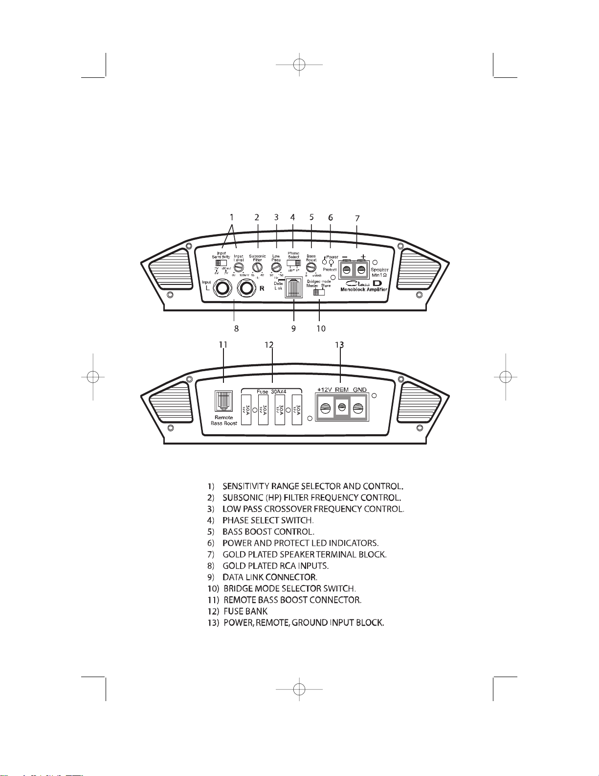
FRONT AND REAR CONNECTIONS AND AUDIO CONTROLS
The front panel of the EXL1200D contains
connections for RCA Inputs, Speaker and Audio
Controls as shown below.
EXL 1200D Manual.qxd 4/25/05 9:30 AM Page 2
Page 5

OPERATION AND INSTALLATION MANUAL
3
SENSITIVITY RANGE SELECTOR AND
CONTROL – The switch allows you to select and
adjust the nominal operating level of the
amplifier. The range is selectable from either 100
mV to 2.0 V. or 2 V. to 8.0 V.
SUBSONIC FILTER – This allows you to tune the
response of the amplifier at very low frequencies.
This can increase efficiency of your system and
even protect your drivers from over excursion in
vented boxes.
LOW PASS FREQUENCY CONTROL – This
allows you to tune the response of the amplifier at
higher BASS frequencies to match your systems
requirements.
PHASE SWITCH – Used to invert the Phase of
the output to the speaker.
BASS BOOST CONTROL – Again used to tune
amplifier response by adding up to 18 decibels of
Boost at 42 HZ.
POWER and PROTECT led indicators – When
the unit is powered on and operating correctly the
POWER led will illuminate. When the unit is on
but in a fault condition the PROTECT led will
illuminate
SPEAKER TERMINAL BLOCK – GOLD PLATED
solid brass machined terminals for delivering very
high current to the speakers.
GOLD PLATED RCA INPUTS – The RCA input
terminals are GOLD PLATED to ensure the highest
quality contacts and the lowest noise in your
audio system.
DATA LINK - The best way to use two amplifiers
is to use the DATA LINK cable provided. This
feature synchronizes the POWER SUPPLY and
HIGH CURRENT OUTPUT STAGE of the SLAVE
amplifier to the MASTER amplifier. This in turn
increases efficiency, and SPL while reducing noise
and eliminating the need for any adjustments of
the slave amplifier controls.
BRIDGE MODE SELECTOR SWITCH - For
installations using one amplifier set this to
MASTER. When installations include two
amplifiers setting this switch to SLAVE (in
conjunction with using the DATA LINK CABLE) will
cause the SLAVE amplifier to function identical to
the MASTER amplifier.
REMOTE BASS CONTROL – Use this control to
control BASS levels from the comfort your of
drivers seat.
FUSE BANK – These are the fuses.
POWER, REMOTE, GROUND INPUT BLOCK –
Battery power, Ground, and Remote input
connections are made here.
EXL 1200D Manual.qxd 4/25/05 9:30 AM Page 3
Page 6

CERWIN-VEGA! EXL1200D POWER SYSTEM AMPLIFIER
4
INSTALLATION
This section lists Mounting and Wiring
Precautions for installing a Cerwin-Vega!
EXL1200D. Combined with the experience of a
professional installer, these safeguards provide
enough detail to successfully complete an
installation. If you do not have the necessary
skills, do not install the amplifier yourself.
Instead, see your authorized Cerwin-Vega!
dealer for installation recommendations.
MOUNTING PRECAUTIONS
Although the Cerwin-Vega! EXL1200D
incorporates heat sinks and protection circuits,
mounting the amplifier in a tight space without
any air movement can still damage internal
circuitry over time. Choose a site that provides
adequate ventilation around the amplifier. For easy
system set-up, mount the amplifier so the front
panel controls will be accessible after installation.
In addition, observe the following precautions:
1. For the most efficient cooling, mount the
amplifier so cool air runs along the length of
the fins rather than across them. Remember,
any moving air will dissipate heat.
2. Mount the amplifier on a rigid surface.
Avoid mounting to subwoofer enclosures
or areas prone to vibration. Do not install
the amplifier on plastic or other
combustible materials.
3. Prior to drilling, make sure proposed
mounting holes will not cut into the fuel
tank, fuel lines, brake lines (under chassis)
or electrical wiring.
WIRING PRECAUTIONS
Read all wiring precautions. If you are not sure
of the connections, contact your authorized
Cerwin-Vega! dealer.
1. Before installation, make sure the source
unit Power switch is in the OFF position.
2. Disconnect the negative (-) lead of the battery
before making any power connections.
3. When making connections, be sure that
each connection is clean and secure.
Insulate final connections with electrical
tape or shrink tubing. Failure to do so may
damage your equipment.
4. A secure clean ground connection is
critical to the performance of your CerwinVega! amplifier. Use the shortest ground
wire possible and securely connect to the
car chassis to minimize resistance and
avoid noise problems.
5. Add an external fuse on the amplifier’s
positive (+) power lead and connect it as
close as possible to the vehicle’s (+)
battery terminal. Use a rating that equals
the total current consumption at full
output of all amplifiers in the system.
Adding an external fuse will protect the
electrical system from short circuits that
can cause a fire.
EXL 1200D Manual.qxd 4/25/05 9:30 AM Page 4
Page 7

OPERATION AND INSTALLATION MANUAL
5
6. Refer to Figure 6 when making electrical
connections. Connect the amplifier’s positive
(+) lead via a fuse directly to the positive (+)
terminal on the battery. Do not connect this
wire to the car’s fuse panel. Use red-insulated
10-gauge (or larger) wire for the amplifier’s
positive (+) power lead and the same-gauge
black-insulated wire for the ground.
7. When replacing the amplifier’s fuse, always use
one having the same current rating. Substituting
a higher-rated fuse or a slow-blow type can
result in serious damage to the amplifier.
8. Never ground the speakers to the vehicle
chassis or body.
9. Make sure that your vehicle’s electrical
system (alternator, battery, etc.) is capable of
handling the additional load. If you are
planning a multi-amplifier system, you may
need to add a second battery and possibly
upgrade the alternator with a higher-output
rated model. Consult your authorized CerwinVega! dealer for recommendations.
10. To avoid noise problems, run the amplifier’s
positive (+) power lead along one side of the
vehicle to the battery.Run the remote turn-on
wire and RCA audio cables down the center,
and route the speaker wires along the
remaining side. If wires must cross, run them
perpendicular to each other.
11. When creating passage holes for the power
wire, use grommets to eliminate any sharp
edges created during drilling. This will protect
the wire from being nicked and causing a
short circuit.
12. Extra cable can cause signal loss and act as
an “antenna” for noise. Use only high-quality
RCA cables that are no longer than necessary
to make a direct connection with the source
unit or equalizer.
WIRING PRECAUTIONS (cont.)
EXL 1200D Manual.qxd 4/25/05 9:31 AM Page 5
Page 8

CERWIN-VEGA! EXL1200D POWER SYSTEM AMPLIFIER
6
WIRING
Front
Rear
EXL 1200D Manual.qxd 4/25/05 9:31 AM Page 6
Page 9

OPERATION AND INSTALLATION MANUAL
7
WIRING
EXL 1200D Manual.qxd 4/25/05 9:31 AM Page 7
Page 10

CERWIN-VEGA! EXL1200D POWER SYSTEM AMPLIFIER
8
WIRING
EXL 1200D Manual.qxd 4/25/05 9:31 AM Page 8
Page 11

OPERATION AND INSTALLATION MANUAL
9
WIRING
EXL 1200D Manual.qxd 4/25/05 9:31 AM Page 9
Page 12

CERWIN-VEGA! EXL1200D POWER SYSTEM AMPLIFIER
10
Set the SUBSONIC filter control to the minimum
frequency. Set the LOW PASS control to the
maximum frequency. Set the BASS BOOST control
to 0. Adjust the INPUT LEVEL control so you can
clearly hear the response of the system. Adjust
the LOW PASS control to the desired frequency
for the best system response. Adjust the
SUBSONIC filter slowly until the reduction in
BASS output becomes audible. Adjust the BASS
BOOST as desirable.
After completing the installation, follow these
steps to set the Gain Control and then perform
the Final System Checks.
1. Turn the Gain Control all the way counterclockwise.
2. Turn the vehicle’s Ignition Switch to the ON
position. Then turn the ON/OFF Switch on
the source units to the ON position. Set all
Tone or Equalization Controls to “flat”
positions and turn Loudness off.
3. Play a CD or Tape and set the Volume
Control at 75% of full level. Note: If the
system uses an equalizer, set its frequency
controls to “flat” positions.
4. Slowly increase the Gain Control. Stop when
you hear a slight distortion of audio.
SETTING THE GAIN
SETTING UP THE AMPLIFIER CONTROLS
EXL 1200D Manual.qxd 4/25/05 9:31 AM Page 10
Page 13

OPERATION AND INSTALLATION MANUAL
11
TROUBLESHOOTING
1. Start the engine and turn on the source unit.
After a two-second delay, slowly increase the
Volume Control and listen to the audio. If you
hear any noise, static, distortion or no sound at
all, check the connections, and also refer to
Troubleshooting. Depending on your system
design, the levels may become quite loud even
at low Volume Control settings. Until you get an
“audio feel” of the system’s power, use care
when adjusting controls.
2. Turn the Balance Controls to their extreme
positions and listen to the results. Audio
imaging should match control settings (audio
from the left speaker when balance is left).
3. Increase the volume and verify that the
amplifier reproduces audio (at full frequencies)
without distortion. If you hear distortion, check
the connections and verify that the Gain
Control is set correctly. Another possibility is
damaged speakers or under-powered speakers.
Once again refer to Troubleshooting for
additional help.
Problem: No Audio.
Solution:
• Low or no remote turn-on voltage. Check
remote connections at amplifier and source unit.
• Blown amplifier fuse. Replace with new fastblow fuse (same rating). Power wires not
connected. Check battery and ground wiring
at amplifier; also check battery connections.
• Speaker leads shorted. Check speaker
continuity to ground, it should not show a
common ground.
• Speakers not connected or are blown. Check
speaker connections at amplifier, measure coil
impedance.
Problem: Audio cycles on and off.
Solution: Thermal protection circuits are
shutting amplifier off. Check location for
adequate ventilation; consult an authorized
Cerwin-Vega! Audio Dealer.
Problem: Distorted audio.
Solution: Gain is not set properly, or damaged
speaker cones. Review Setting Gain; inspect
each speaker cone for signs of damage (i.e.
frozen cone, burning smell, etc.)
FINAL SYSTEM CHECKS
EXL 1200D Manual.qxd 4/25/05 9:31 AM Page 11
Page 14

CERWIN-VEGA! EXL1200D POWER SYSTEM AMPLIFIER
12
Frequency Response
Signal Noise Ratio
THD
Input Sensitivity Low Level
Cont. Power Output
Current Consumption at output @ max power
Dimensions
Weight
15Hz ~ 150Hz +/- 1 dB
>87 db
.05% @ 100Hz
100mV ~ 8 V
1200w (1200w x 1) @.05% THD, 1-Ohm load
120A @ 1200 Watts
2-1/2”H x 9-1/2 “ W x 19-1/4” L
13 lbs.
PRODUCT SPECS FOR THE EXL1200D
Problem: Audio lacks punch.
Solution: Speakers wired incorrectly, which
causes cancellation of bass frequencies.
Check polarity of wires from amplifier to each
speaker as defined by the system design.
Problem: Amplifier fuse keeps blowing.
Solution: Incorrect wiring or short circuit.
Review Installation and check all wiring
connections.
Problem: Whining or ticking noise in the
audio with engine on.
Solution: Amplifier is picking up alternator
noise or radiated noise.Turn down input gain;
move audio cables away from power wires.
Check power and ground connections on
amplifier; install an in-line noise filter on
source unit’s power wire; check alternator
and/or voltage regulator; test for weak
battery or add water to battery.
TROUBLESHOOTING (Cont.)
EXL 1200D Manual.qxd 4/25/05 9:31 AM Page 12
Page 15

OPERATION AND INSTALLATION MANUAL
13
Notes
EXL 1200D Manual.qxd 4/25/05 9:31 AM Page 13
Page 16

9340 De Soto Ave., Chatsworth, CA 91311
Phone: 1-805-584-9332 • Fax: 1-805-583-0865 • Email: info@cerwin-vega.com
EXL 1200D Manual.qxd 4/25/05 9:31 AM Page 14
 Loading...