

Page 1

CVM-1224FXUSB
CVM-1624FXUSB
PROFESSIONAL AUDIO MIXER
TABLE DE MIXAGE AUDIO PROFESSIONNELLE
MESA DE MEZCLAS PROFESIONAL
PROFESSIONELLEN AUDIO-MIXER
C
(p. 2)
(p. 58)
(S. 86)
(p. 30)
Page 2
IMPORTANT SAFETY INSTRUCTIONS
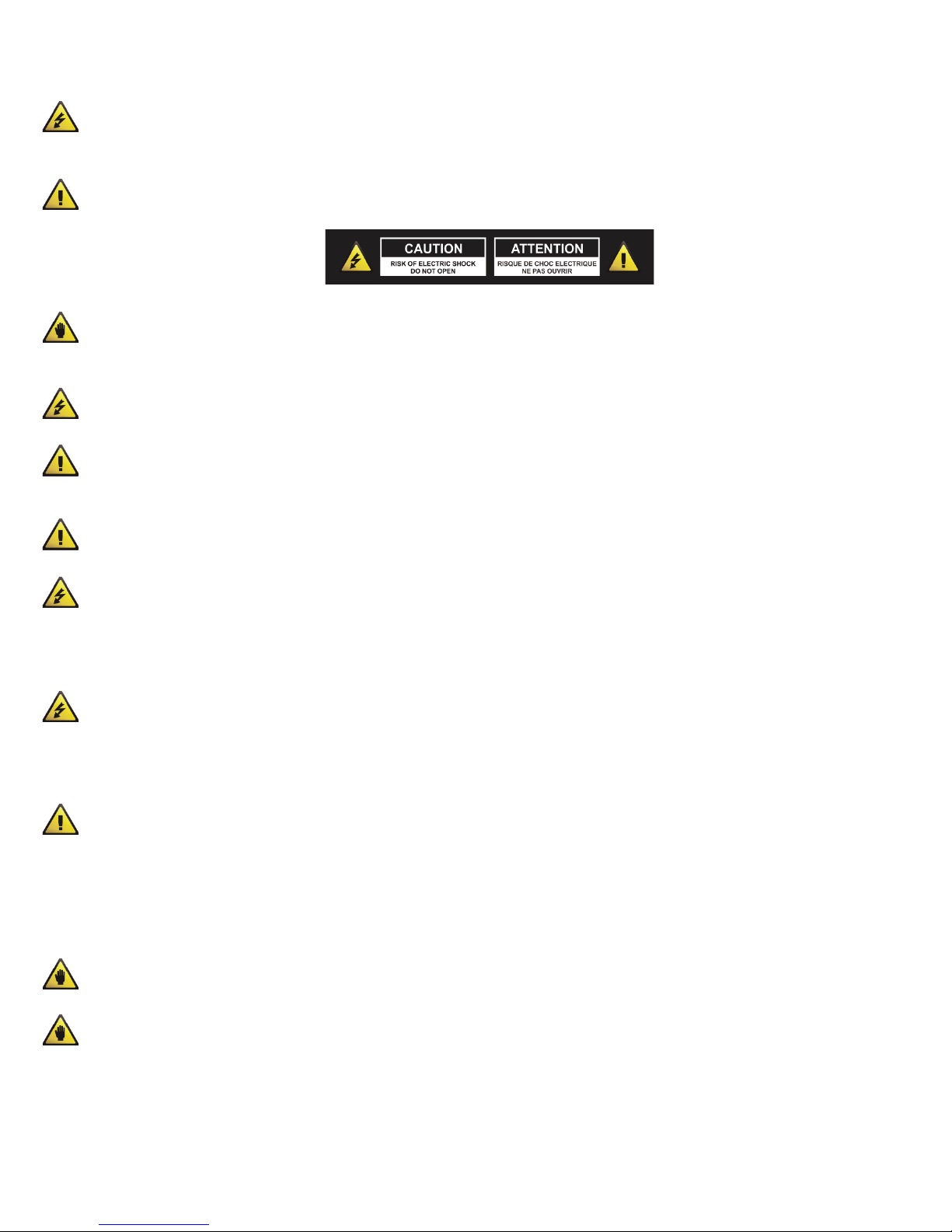
CAUTION: THE LIGHTNING FLASH WITH AN ARROWHEAD SYMBOL WITHIN AN EQUILATERAL TRIANGLE IS INTENDED TO ALERT
THE USER TO THE PRESENCE OF UN-INSULATED DANGEROUS VOLTAGE WITHIN THE UNITS ENCLOSURE THAT MAY BE OF
SUFFICIENT MAGNITUDE TO CONSTITUTE A RISK OF ELECTRIC SHOCK TO PERSONS.
WARNING: THE EXCLAMATION POINT WITHIN AN EQUILATERAL TRIANGLE IS INTENDED TO ALERT THE USER TO THE PRESENCE
OF IMPORTANT OPERATING AND MAINTENANCE (SERVICING) INSTRUCTIONS IN THE LITERATURE ACCOMPANYING THE
PRODUCT.
NOTE: THE HAND WITHIN AN EQUILATERAL TRIANGLE IS INTENDED TO ALERT THE USER TO SPECIFIC GUIDANCE AND
INFORMATION REGARDING THE OPERATION OF THE UNIT, AND SHOULD BE READ FULLY BEFORE USING THE UNIT FOR THE
FIRST TIME.
CAUTION: TO REDUCE THE RISKS OF FIRE OR ELECTRIC SHOCK DO NOT REMOVE ANY COVERS, OR OPEN THE UNIT. THERE ARE
NO USER-SERVICABLE PARTS INSIDE. ALL SERVICING SHOULD BE REFERRED TO QUALIFIED SERVICE ENGINEERS.
WARNING: READ AND FOLLOW ALL THE SAFETY AND OPERATING INSTRUCTIONS BEFORE CONNECTING OR USING THIS UNIT.
RETAIN THIS USER MANUAL FOR FUTURE REFERENCE. ALL WARNINGS ON THE UNIT AND ITS PACKAGING SHOULD BE READ AND
FOLLOWED.
WARNING: This product contains a chemical known to the State of California to cause cancer and birth defects or other
reproductive harm.
CAUTION: To reduce the risks of fire or electric shock do not expose this product to rain or moisture. Do not use this product
near water; for example, near a bath tub, washbowl, kitchen sink, laundry tub, in a wet basement or near a swimming pool.
Unplug the unit from the wall outlet before cleaning. Never use thinner, cleaning fluids, solvents or chemically impregnated
cloths. For cleaning always use a soft dry cloth. Unplug this product during lightning storms or when unused for long periods of
time.
CAUTION: The unit should be installed so that its location or position does not interfere with its proper ventilation. For example,
it should not be situated on a bed, sofa, rug or similar surface that may block the ventilation openings; or placed in a built-in
installation, such as a bookcase or cabinet, that may impede the flow of air through its ventilation openings. The unit should be
situated from heat sources such as radiators, heat registers, stoves or other devices (including amplifiers) that produce heat. No
naked flame sources, such as lighted candles, should be placed on, or near the unit.
WARNING: Do not place this unit on an unstable surface, cart, stand or tripod, bracket or table. The unit may fall, causing
serious injury to a child or adult and serious damage to the unit. Use only with a cart, stand, tripod, bracket or table
recommended by the manufacturer or sold with the unit. Any mounting of the device on a wall or ceiling should follow the
manufacturer’s instructions and should use a mounting accessory recommended by the manufacturer. An appliance and cart
combination should be moved with care. Quick stops, excessive force and uneven surfaces may cause the appliance and cart
combination to overturn. Use only with the cart, stand, tripod, bracket, or table specified by the manufacturer, or sold with the
apparatus. When a cart is used, use caution when moving the cart/apparatus combination to avoid injury from tip-over.
NOTE: Should the unit become damaged beyond repair, or reaches the end of its life, please con sult the regulations regarding
disposal of electronic products in your region.
NOTE: Cerwin-Vega cannot be held responsible for damage, and, or including data loss caused by improper use of the unit and
or the applications provided for use with the unit.
2
Page 3

IMPORTANT SAFETY INSTRUCTIONS
CAUTION TO PREVENT ELECTRIC SHOCK, MATCH WIDE BLADE OF PLUG TO WIDE SLOT FULLY INSERT.
ENGLISH: The apparatus shall be connected to a Mains socket outlet with a protective earthing connection.
GERMAN: Das Gerät ist eine Wandsteckdose mit einem Erdungsleiter angeschlossen werden.
FRENCH: L’appareil doit être connecté à une prise secteur avec connexion à la terre.
SPANISH: El aparato estará conectado a una toma de red eléctrica con una conexión a tierra.
ITALIAN: L’apparecchio deve essere collegato a una presa di rete con una connessione a terra protettiva.
1. The unit and power supply should only be connected to a power supply outlet only of the voltage and frequency marked on
its casing.
2. Protect the power cable from being walked on or pinched particularly at plugs, convenience receptacles, and the point where
they exit from the apparatus.
3. Do not defeat the safety purpose of the polarized or grounding-type plug. A polarized plug has two blades with one wider
than the other. A grounding type plug has two blades and a third grounding prong.
The wide blade or the third prong is provided for your safety. If the provided plug does not fit into your outlet, consult a
qualified electrician for replacement of the obsolete outlet.
4. If the mains plug supplying this product incorporates a fuse then it should only be replaced with a fuse of identical or lower
rupture value.
5. Never use a damaged or frayed power cable; this can introduce serious risk of exposing lethal voltages.
6. The power supply cable of the unit should be unplugged from the wall outlet when it is to be unused for a long period of time.
7. Only use attachments/accessories specified by the manufacturer.
DO NOT ATTEMPT SERVICING OF THIS UNIT YOURSELF. REFER SERVICING TO QUALIFIED SERVICE PERSONNEL.
Upon completion of any servicing or repairs, request the assurance that only Factory Authorized Replacement Parts with the
same characteristics as the original parts have been used, and that the routine safety checks have been performed to guarantee
that the equipment is in safe operating condition.
REPLACEMENT WITH UNAUTHORIZED PARTS MAY RESULT IN FIRE, ELECTRIC SHOCK OR OTHER HAZARDS.
ATTENTION POUR …VITER LES CHOC ELECTRIQUES, INTRODUIRE LA LAME LA PLUS LARGE DE LA FICHE DANS LA BORNE
CORRESPONDANTE DE LA PRISE ET POUSSER JUSQUíAU FOND.
This unit should be serviced by qualified service personnel when:
The power cord or the plug has been damaged
Objects have fallen, or liquid has been spilled into the unit
The unit has been exposed to rain or liquids of any kind
The unit does not appear to operate normally or exhibits a marked change in performance
The device has been dropped or the enclosure damaged.
3
Page 4

REGULATORY CERTIFICATION
Cerwin-Vega declares under our sole responsibility that this product, to which this declaration relates, is in conformity with the
following standards:
The Declarations of Conformity can be obtained from Gibson Europe BV - Kamerlingh Onnesweg, 2 - 4131 PK Vianen - The
Netherlands Tel : +31 347 32 40 10 - Fax : +31 347 32 40 15
This device complies with Part 15 of the FCC Rules. Operation is subject to the following two conditions: (1) this device may not
cause harmful interference, and (2) this device must accept any interference received, including interference that may cause
undesired operation.
Warning: Changes or modifications to this unit not expressly approved by the party responsible for compliance could void the user's
authority to operate the equipment.
NOTE: This equipment has been tested and found to comply with the limits for a Class B digital device, pursuant to Part 15 of the FCC
Rules.
These limits are designed to provide reasonable protection against harmful interference in a residential installation. This equipment
generates, uses, and can radiate radio frequency energy and, if not installed and used in accordance with the instructions, m ay cause
harmful interference to radio communications. However, there is no guarantee that interference will not occur in a particular
installation. If this equipment does cause harmful interference to radio or television reception, which can be determined by turning
the equipment off and on, the user is encouraged to try to correct the interference by one or more of the following measures:
– Reorient or relocate the receiving antenna.
– Increase the separation between the equipment and receiver.
– Connect the equipment into an outlet on a circuit different from that to which the receiver is connected.
– Consult the dealer or an experienced radio TV technician for help.
This Class B digital apparatus complies with Canadian ICES-003.
4
Page 5

INTRODUCTION
UNPACKING & INSTALLATION
FEATURES
Thank you for your decision to purchase Cerwin-Vega’s new CV Mixer Series professional audio mixer! Engineered for
superior sound reproduction, the CV Mixer Series line of professional audio mixers deliver top quality audio at an
affordable price. The CV Mixer Series offer a standard of reliability and efficiency that makes them the perfect solution
for every DJ, musician, and sound engineer. Welcome to a new level of professional quality sound performance!
Although it is neither complicated to install, nor difficult to operate your new mixer, a few minutes of your time are
required to read this manual for a properly wired installation, and to become familiar with the unit’s features. Please
take great care in unpacking the unit and do not discard the carton and other packing materials. They may be needed
when moving the unit and are required if it ever becomes necessary to return the unit for service. Never place the unit
near a radiator, in front of heating vents, in direct sunlight, in excessive humidity, or dusty locations to avoid damages
and to guaranty a long reliable use. Connect the unit with the system components according to the description on the
following pages.
• 4 Mono and 4 Stereo line input with 6 XLR microphone inputs (12-Channel CVM-1224FXUSB)
• 8 Mono and 4 Stereo line input with 10 XLR microphone inputs (16-Channel CVM-1624FXUSB)
• Main L/R ¼” jack and XLR output and ALT 3/4 ¼” jack output
• 3-Band channel equalizer designed for ±15 dB (HF, LF) and ±12 dB (MF) control on input channel
• Phantom power (+48V) switch for easy connection of condenser microphones that typically require an external
power supply
• Detachable rack ears for mounting in a standard 19” rack enclosure
• Peak LED indicator to check on the signal input of each microphone channel
• Gain (trim) level control with sensitivity markings for both microphone and line inputs
• Low Cut (HPF) switch toggles the filter, with a cut-off frequency at 75Hz, to eliminate background microphone
rumble
• Pre/Post switch to set the aux signal as pre- or post-fader for foldback/monitoring mix or to preserve the
wet-to-dry ratio on aux sends
• Aux and EFX controls to adjust the level of the signal sent to the respective bus
• Pan control (mono channel) to position the signal across the master left and right bus
• Balance control (stereo channel) to adjust the level between left and right signals
• PFL (pre-fade listen) switch with adjacent indicator to allow the mixer to listen to each channel before it reaches
the main mix
• Built-in Vega-effects 24-bit digital signal processor with 100 selectable programs including reverb, echo, chorus
and flange
• Vega-effects master or footswitch on/off control
• USB input and output for laptop computer playback and recording
• Tape in stereo RCA jacks for connection to a CD or MP3 player
• Record out stereo RCA jacks for connection to a audio recorder
• Individual channel and main level control using 60mm faders
• Level control for headphone and control room connections
5
Page 6
FRONT PANEL CONTROLS
– CHANNEL CONTROL SECTION
CONTROL
MAX.
BOOST/CUT
FREQUENCY
TYPE
HIGH
±15dB
12kHz
Shelving
MID
±12dB
2.5kHz
Peaking
LOW
±15dB
80Hz
Shelving
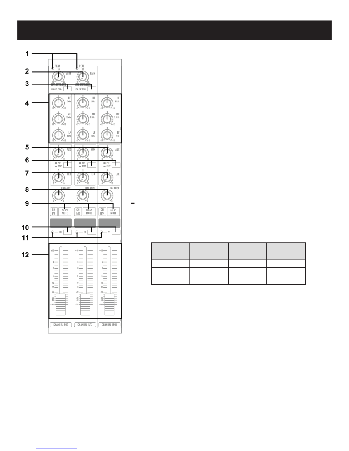
(1). PEAK LED INDICATOR
This LED indicators lets you check the level of the signal input to the channel.
The peak indicator lights when the input signal reaches 5dB below the
channel’s clipping point. This indicator shows the level of the Post-EQ /
pre-fader signal. If the PEAK indicator lights more than briefly on high-level
transients, you should use the GAIN control to decrease the input sensitivity
of the channel. If this does not work, reduce the output level of the connected
source.
(2). GAIN CONTROL
According to the level of the input signal, use this knob to adjust the input to
an appropriate level. The best balance of S/N and dynamic range will be
achieved if you adjust the GAIN control so that the peak indicator lights
occasionally. This control adjusts the channel’s mic input sensitivity between
-50dB and -6dB and the line input sensitivity between -30dB and +14dB. The
mono/stereo combination input channels have a sensitivity of +20dB to
-20dB.
(3). HPF (High-Pass Filter, cut frequencies below 75Hz)
This switch toggles the HPF on or off. To turn the HPF on, press the switch in
).
(
(4). 3 BAND EQUALIZER CONTROLS
This is a 3-band equalizer with center frequencies, range and type as shown
below. The frequency response is flat when all knobs are in the “0” position.
(5). AUX CONTROLS
This knobs control the level of the signals sent to AUX bus.
(6).PRE/POST SWITCH
This button determines whether the AUX signal is Pre or Post fader. Pre
means not affected by the position of the channel fader. Post means is
affected by the position of the channel fader.
(7). EFX CONTROLS
This knobs control the level of the signals sent to EFX bus. The channel signals mixed by this bus have their overall level
set by the EFX SEND Control to the EFX SEND jack on the front panel. The EFX bus signal is also fed into the internal
digital signal processor. Since this control is placed after the channel fader, the signal level will be affected by the
channel fader setting.
6
Page 7

FRONT PANEL CONTROLS
– CHANNEL CONTROL SECTION (continued)
(8). PAN/BAL CONTROL
PAN (Mono Channel)
This control pans the channel signal across the master L and R buses, thus determining the perceived position of the
sound from that channel in the output stereo sound field. If a PAN control is set all the way to the left, for example, the
sound from that channel will be heard from the left speaker system only. If it is set all the way to the right, the sound
will be heard from the right speaker system only. Intermediate settings will cause the sound to appear at corresponding
locations in the stereo sound field.
BALANCE (Stereo Channel)
This control adjusts the balance or the L/R position of the stereo input signal. Turning the BALANCE control to the left of
center moves the apparent source toward the MAIN MIX L moves the source toward the MAIN MIX R bus.
(9). MUTE/ALT 3/4 SWITCH
When the Mute/ALT 3/4 switch is depressed, a channel output will be routed to the ALT 3/4 output instead of the MAIN
L/R output. ALT 3/4 bus offers you a second independent stereo sub mix with its own sub master stereo fader.
(10). PFL SWITCH
When this switch is depressed, the channel input signal can be routed to the PFL bus. This switch allows you to monitor
the pre-fader channel input signal through headphone outputs and control room outputs.
(11). PFL INDICATOR
This indicator lights when the PFL switch is turned on.
(12). CHANNEL FADER
This is the channels main level control. It determines the level of the signal that is sent from the channel to the master
mixing and effect buses. It is the settings of the input channel faders that determine the mix, or the balance of sound
levels between the instruments or other sources connected to the inputs. When a channel is not being used, its volume
should be set at the minimum position to prevent the addition of unwanted noise to the main program signal.
7
Page 8
FRONT PANEL CONTROLS
– MAIN CONTROL SECTION
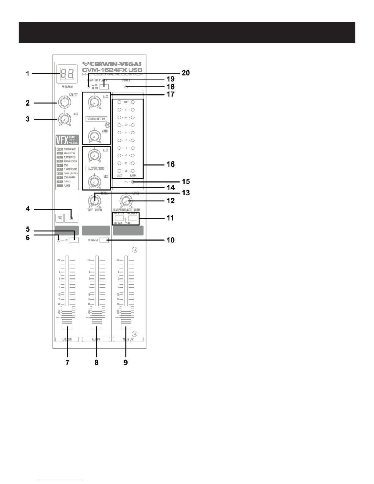
(1). VFX PROGRAM DISPLAY
The Program LED displays the number of the
selected effects program. Use the table located
above the VFX (EFX)ON/OFF switch to lookup the
desired effects.
(2). VFX PROGRAM SELECT SWITCH
This program knob selects one of the 100 built-in
digital effects, for each number you select. The VFX
programs feature a 24 Bit Digital Effects processor
with high quality, studio grade effects like Delay,
Chorus and Reverb.
(3). AUX PRE CONTROL
Adjust the level of the signal sent from the internal
digital effect to the AUX bus.
(4). VFX (EFX) ON/OFF SWITCH
This switch turns the internal digital effect on/off.
(5). PFL SWITCH
Set this switch on if you wish to output the effect
signal to the PFL bus.
(6). PFL INDICATOR
This indicator lights when the PFL switch is turned
on.
(7). EFX RTN Fader
Adjust the level of the signal sent from the internal
digital effect to the main bus.
(8). ALT 3/4 OUTPUT FADER
This fader adjusts the final level of the combined
stereo signal sent to the ALT 3/4 output jacks.
(9). MAIN L/R MASTER FADER
These faders adjust the final level of the combined
signals from all channels.
(10). TO MAIN L/R SWITCH
When this switch is on, the signal of each ALT 3/4 will
be sent to the MAIN L/R buses.
8
Page 9
FRONT PANEL CONTROLS
– MAIN CONTROL SECTION (continued)
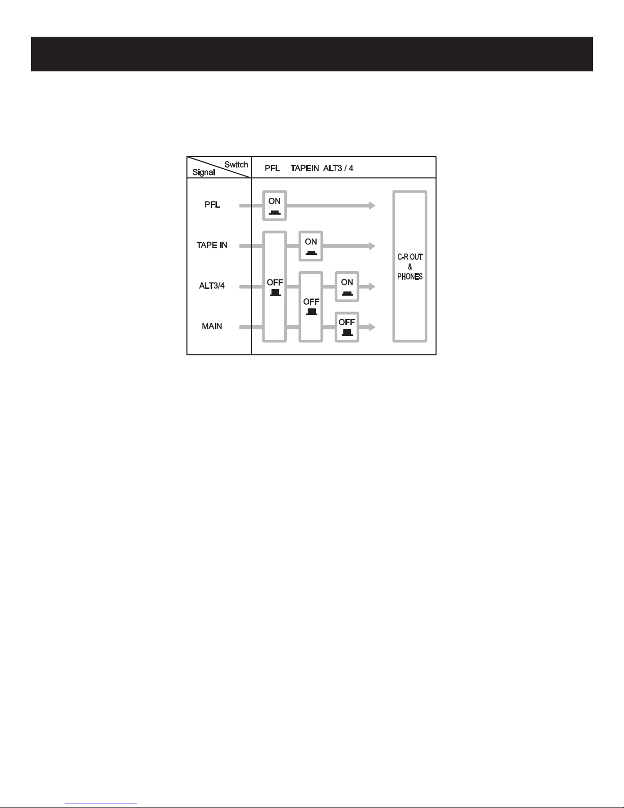
(11). Level-Meter Signal Switches (MAIN-ALT 3/4 Toggle Switch and TAPE IN Switch)
These level-meter switches, together with the channel PFL switches, select the signal that is sent through the CTRL
ROOM/HEADPHONE control to the CONTROL ROOM out jacks, the HEADPHONE jack, and the level meter. The following
illustration shows how the switch settings correspond to the signal selection.
(12). CTRL ROOM /PHONES CONTROL
Controls the level of the signal output to the HEADPHONE jack and CONTROL ROOM L and R jacks.
(13). TAPE IN CONTROL
This control adjusts the level of the playback signal that is inserted to the master mixing bus from the TAPE IN RCA
jacks on the top panel.
(14). MASTER SEND
* Master AUX Control
Adjust the level of the signal on the AUX bus to the corresponding AUX SEND jack.
* Master EFX Control
Adjust the level of the signal on the EFX bus. This is the signal that is output through the EFX SEND jack.
(15). PFL INDICATOR
This indicator lights when the PFL switch is turned on.
(16). OUTPUT LEVEL METER
A vertical row of ten LED shows the continuous output level of MAIN OUTPUT L/R. This type of display is highly visible
under poor lighting conditions. The 0 LED means an output level of +4dB for +4dB output (that’s the rated level).
(17). STEREO RETURN CONTROL
* AUX CONTROL
Adjust the level of the mixed L/R signal sent from the RETURN jack (L (MONO) and R) to the AUX bus.
* MAIN CONTROL
Adjust the level of the mixed L/R signal sent from the RETURN jack (L (MONO) and R) to the MAIN L/R bus.
9
Page 10

FRONT PANEL CONTROLS
– MAIN CONTROL SECTION (continued)
(18). POWER INDICATOR
This indicator lights when the power switch is turned on.
(19). PHANTOM POWER SWITCH
This switch toggles phantom power on or off. If you set the switch on, the mixer supplies power to all channels that
provide XLR microphone input jacks. Set this switch on when using one or more condenser microphones.
WARNING, be sure the microphone you are using is compatible or will not be affected by phantom power. Failure
to do so may result in equipment damage. Please see the notes below:
NOTE: When this switch is on, the mixer supplies DC +48V power to pins 2 and 3 of all XLR-type MIC INPUT jacks.
NOTE: Be sure to leave this switch off (
NOTE: When the switch is pressed on (
jacks. Note, however, that the switch may be left on without problem when connecting to balanced dynamic
microphones. Be sure the balanced dynamic microphone you are using is not affected by phantom power in any way
before connection is made. The same applies with ribbon microphones.
NOTE: When the switch is pressed on (
XLR input jacks. Do not plug instrument outputs into the XLR input jack unless you know for certain it is safe to do so.
NOTE: To avoid damage to the speakers, be sure to turn off the amplifier (or powered speakers) before turning this
switch on or off. We also recommend that you turn all controls (MAIN L/R, CTRL ROOM / HEADPHONE, etc) to minimum
settings before operating the switch, to avoid risk of loud noises that could cause hearing loss or device damage.
(20). PHANTOM POWER INDICATOR
This indicator lights when the phantom power switch is turned on.
) if you do not need phantom power.
), be sure that only condenser microphones are connected to the XLR input
), do not use single-ended (unbalanced) microphones or instruments into the
10
Page 11

FRONT PANEL CONTROLS
– INPUT/OUTPUT CONNECTORS
(1). Channel Input Jacks
MIC JACKS
A 3-pin XLR-type connector is used for balanced low impedance microphone inputs. (pin 1: sleeve, 2: hot, 3:cold)
BALANCED LINE IN JACKS
A standard 1/4” phone jack is used for balanced or unbalanced line level signals. Examples of line level signals include
most electronic keyboards, synthesizers, turn-tables (with appropriate pre-amps), tape decks and the line outputs from
other mixers.
(2). CHANNEL INSERT I/O JACK
These are input/output jacks located between the head-amplifier and the high pass filter. These jacks allow you to use
graphic equalizers, compressors, noise filters, or other devices.
(3). CHANNEL INPUT JACKS
These are unbalanced stereo line input jacks. Two jack types are provided phone type and RCA pin type.
(4). STEREO RETURN L (MONO), R Jack
These are unbalanced ¼” phone-type line input jacks. The signal received by these jacks is sent to the MAIN bus and AUX
bus. These jacks are typically used to receive a return signal from an external effect (reverb, delay, etc.)
NOTE: These jacks can also be used as an auxiliary stereo input. If you connect to the L (MONO) jack only, the mixer
will recognize the signal as monaural and will propagate the identical signal on both L and R jacks.
11
Page 12

FRONT PANEL CONTROLS
– INPUT/OUTPUT CONNECTORS (continued)
(5). TAPE IN JACKS
These RCA pin jacks input a stereo sound source. Use these jacks when you want to connect a CD or DAT directly to the
mixer for monitoring.
NOTE: You can adjust the signal level using the TAPE IN control in MAIN control section.
(6). REC OUT JACKS
The REC OUT jacks send the pre-fader signal from the master bus for recording by the tape deck.
(7). SEND JACKS
* AUX: These are unbalanced phone jacks-type output jack. This jack output the signal form AUX bus, respectively. You
use this jack, for example, to connect to an effector or to a cue box or other such monitoring system.
* EFX: These are unbalanced phone jacks-type output jack that output the signal form the EFFECT bus. You use this jack,
for example, to connect to an external effector
(8). FOOT SWITCH JACK
This phone input jack can connect to a foot switch. With the foot switch connected, you can use your foot to toggle the
digital effects ON and OFF.
(9). ALT 3/4 OUTPUT JACKS
These are unbalanced 1/4” phone-type output jacks which output the signals of the ALT 3/4 bus. Use these jacks to
connect to the input jack of a digital recorder, external mixer, or other such device.
(10). MAIN L/R OUTPUT JACKS
These jacks deliver stereo output of the mixer signal. You use these jacks, for example, to connect to the power
amplifiers driving your main speakers. You also use these jacks when you wish to record the signal utilizing the level
control applied by the main fader in the main control section. TRS phone-type balanced output jack.
(11). CONTROL ROOM OUTPUT JACKS
Use these stereo phone-type output jacks to connect to your monitor system.
NOTE: The signal monitored by these jacks is selected by the settings of the MAIN-ALT 3/4 toggle switch, the TAPE IN
switch, and the PFL switches on the input channels.
(12). HEADPHONE JACK
Connect for headphones. This is stereo phone-type output jack (3-conductor TRS).
NOTE: The signal monitored by these jacks is selected by the settings of the MAIN-ALT 3/4 toggle switch, the TAPE IN
switch, and the PFL switches on the input channels.
12
Page 13

REAR PANEL CONTROLS
USB Compatibility*
Windows 7
Windows Vista
Windows XP
MAC OS X
*For compatibility on new operating
systems, please contact Customer Service.
(1). AC ADAPTOR IN CONNECTOR
Connects to the included power adaptor.
NOTE: Use only the adaptor included with this mixer. Use of a different adaptor may result in fire or electric shock.
(2). POWER SWITCH
Use this switch to turn mixer power to ON or OFF.
(3). MAIN L/R OUTPUT XLR JACK
These jacks deliver stereo output of the mixer signal. You use these jacks, for example, to connect to the power
amplifiers driving your main speakers. You also use these jacks when you wish to record the signal utilizing the level
control applied by the main fader in the main control section.
(4). USB PORT
A standard Type-A to Type-B cable is required to connect the mixer to a computer or laptop. The built-in stereo USB
audio interface allows you to record and playback from a desktop or laptop computer using virtually any digital
recording software. Payback adjustment is made using the TAPE IN/USB level knob. Connecting the audio mixer to your
computer is a simple procedure that takes just a few minutes. Since the Cerwin-Vega audio mixer is USB compliant, you
can use either a MAC or Windows-based PC. You will find detailed instructions on setting up the audio mixer in either
MAC or Windows-based computers in the following sections of this manual.
13
Page 14

USB AUDIO INTERFACE (Windows 7)
1. The first time you plug the audio mixer into a USB
port, Windows will install the universal drivers for that
port. A balloon tip will pop-up, telling you it recognizes
the connection and will install the device driver.
2. When the drivers have finished installing, the balloon
tip will refresh itself and tell you installation is
complete.
Note: This balloon will not pop up again once the driver
has been installed.
3. Most of the time, you’ll want the output volume from
the computer at the maximum position, but sometimes
it defaults to the middle of the slider, making the output
very quiet. The volume can be increased in several
ways. The simplest is to click the loudspeaker icon in the
system tray and adjust the slider volume level.
4. Press ‘Mixer’ in the volume slider window to open up
the Volume Mixer window. To use the audio mixer as
your default output device, ensure that it is set for
speakers in the Volume Mixer window by setting the
default device to ‘USB Audio CODEC’.
5. Another way to set the default record and playback
to the audio mixer is in the Control Panel. Select the
Sound icon to open up a new window. Right-click on the
icon that lists ‘USB Audio CODEC’ and select ‘Set as
default’. A check mark on the icon indicates the device
is set to default.
6. To prevent system sounds from coming through the
audio mixer, select a different sound device for the
system default, and then choose the audio mixer
manually within your DAW software.
14
Page 15

USB AUDIO INTERFACE (
Windows XP)
1. The first time you plug the audio mixer into a USB
port, Windows will install the universal drivers for that
port. A balloon tip will pop-up, telling you it has found
the USB Audio codec.
2. When the drivers have finished installing, it will say
“Your new hardware is installed and ready to use”
Note: This balloon will not pop up again once the driver
has been installed.
3. Most of the time, you’ll want the output volume from
the computer at the maximum position, but sometimes
it defaults to the middle of the slider, making the output
very quiet. The volume can be increased in several
ways. The simplest is to click the loudspeaker icon in the
system tray and drag the slider to the top.
4. To use the audio mixer as your default input/output
device (for system sounds and programs like Sound
Recorder), ensure that it is set for playback and
recording in the Properties window by setting the
default device to ‘USB Audio CODEC’. Go to Control
Panel and open Sounds, Speech and Audio Devices.
5. In the Properties window, set sound playback to ‘USB
Audio CODEC’. And set sound recording playback to
‘USB Audio CODEC’.
A new window will appear showing a volume slider.
6. To prevent system sounds from coming through the
audio mixer, select a different sound device for the
system default, and then choose the audio mixer
manually within your DAW (digital audio workstation)
software.
15
Page 16

USB AUDIO INTERFACE (MAC
OS X)
1. Connect the audio mixer to your MAC using a
standard USB cable. The LED will light to indicate it is
receiving USB power. The MAC will recognize the USB
audio device and automatically install a universal driver.
2. To select the audio mixer as the computer’s audio
input, open the System Preferences from the dock or
the main Apple Menu.
3. Next open the Sound preference.
4. Now, click in the Input tab and select USB Audio
CODEC. You may notice that the Volume slider sets
itself to the full level. This will allow you to have full
range using audio mixer hardware input level controls.
5. Next, click in the Output tab and select USB Audio
CODEC. You may notice that the Volume slider sets
itself to the full level. This will allow you to have full
range using audio mixer hardware MAIN Volume
control.
At this point you can begin using your audio mixer with
most any audio recording software, but you need to
select it as an input and output device within the DAW.
When selecting the inputs and outputs just look for and
select the USB Audio CODEC.
16
Page 17

POINTS TO REMEMBER
- In all cases, use good quality twin screened audio cable. Check for instability at the output.
- Always connect both conductors at both ends, and ensure that the screen is only connected at one end.
- Do not disconnect the mains earth from each piece of equipment. This is needed to provide both safety and
screen returns to the system start point.
- Equipment which has balanced inputs and outputs may need to be electrically isolated from the equipment rack
and/or other equipment, to avoid earth loops.
It is important to remember that all equipment which is connected to the mains is a potential source of hum and
interference and may radiate both electrostatic and electromagnetic radiation. In addition, the mains will also act as a
carrier for many forms of RF interference generated by electric motors, air-conditioning units, thyristor light dimmers
etc. Unless the earth system is clean, all attempts to improve hum noise levels will be futile. In extreme cases there will
be no alternative but to provide a completely separate and independent ‘technical earth’ to replace the incoming ‘noisy
earth’. However, always consults your local electricity supply authority to ensure that safety regulations are not being
infringed.
17
Page 18

CONNECTIONS
Insert
Screen
Return
Send
Balanced Line
Ground
Cold (-)
Hot (+)
Unbalanced Line
Ground
n/a
Hot (+)
Headphones
Sleeve
Right
Left
XLR
Shield/Ground
Cold (-)
Hot (+)
Table A (1/4” TRS) Sleeve Ring Tip
Table B (XLR) Pin 1 Pin 2 Pin 3
18
Page 19

CONNECTIONS
– CONNECTOR AND CABLE CONFIGURATIONS
19
Page 20

APPLICATIONS
– HOME RECORDING
Setup Procedure
1. Before connecting to microphones and instruments, be sure that all devices are turned off. Also be sure that all
of the mixer’s channel fader and master control faders are set all the way down.
2. For each connection, connect one end of the cable to the relevant microphone or instrument and connect the
other end to the appropriate input jack on the mixer.
3. To avoid causing damage to the speaker, power up the devices in the following order: Peripheral devices ->
mixer -> power amps (or powered speakers)
NOTE: When shutting the system down, turn off the power in the opposite order: Power amps (powered speakers) ->
mixer -> peripheral devices.
NOTE: Where an input channel provides both a MIC INPUT jack and a LINE INPUT jack, you may use either one of these
jack but you may not use both at the same time. Please connect to only one of these jacks on each channel.
20
Page 21

APPLICATIONS
– LIVE PERFORMANCE
21
Page 22

BLOCK DIAGRAM
22
Page 23

GENERAL S
PECIFICATIONS
Maximum Output Level
(0.5% T.H.D. at 1kHz)
+26dB (MAIN L/R), +20dB (ALT 3/4, AUX, EFX, CTRL ROOM)
+20dB (INSERT) more than 100mW (HEADPHONES) @ 33Ω
T.H.D.
<0.1% @ +14dB 20Hz~20kHz (MAIN L/R, ALT 3/4, AUX SEND, EFX SEND, CTRL ROOM)
Frequency Response
20Hz~20kHz, +1/-2dB (MIX L/R, ALT 3/4, AUX SEND, EFX SEND, CTRL ROOM)
Hum and Noise (Average,
20kHz LPF Rs = 150Ω)
-127dB equivalent input noise, -95dB residual noise (MAIN L/R, ALT 3/4, AUX/EFX SEND,
CTRL R
, AUX/EFX send, CTRL ROOM OUT) * Master
fader at nominal level and all channel fader Minimum.
Maximum Voltage Gain
74dB MIC IN to MAIN L/R, 74dB MIC IN to ALT 3/4, 66dB MIC IN to AUX (PRE)
76dB MIC IN to AUX (POST), 76dB MIC IN to EFX (REV), 80dB MIC IN TO CONTROL ROOM
52.5dB MIC IN to REC L/R, 54dB LINE IN to MAIN L/R, 54dB LINE IN to ALT 3/4
46dB LINE IN to AUX (PRE), 56dB LINE IN to AUX (POST), 56dB LINE IN to EFX (REV),
60dB LINE IN to CONTROL ROOM L/R, 44dB ST IN to MAIN L/R, 44dB ST IN to ALT 3/4
16dB AUX RETURN IN to MAIN L/R, 20dB TAPE IN to MAIN L/R
Crosstalk (at 1kHz)
-70dB between input channels, -70dB between input/output channels
Gain Control (mono Input
channel)
44dB Variable (
Gain Control (mono/stereo
combination Input channel)
40dB Variable (
Input Channel Equalization
HIGH: 12kHz shelving, MID: 2.5kHz peaking, LOW: 80Hz shelving * turnover/roll off
frequencies: located 3dB below maximum boost/cut
LED Meters
10-segment LED x2 MAIN L/R, ALT 3/4, PFL, TAPE IN
Channel Indicators
Peak: An indicator for each channel turns on when the pre-channel fader signal is 5dB
below clipping.
Phantom Power
+48V DC
Power Supply
USA/Canada 120VAC / 60Hz
Australia 240VAC / 50Hz
Europe 230VAC / 50Hz
Power Consumption
36W
Weight
3.4 kg (7.5 lbs) CVM-1224FXUSB
5.6 kg (12.3 lbs) CVM-1624FXUSB
Dimension (W x H x D)
328 x 90 x 420 mm (12.9 x 3.5 x 16.5 in) CVM-1224FXUSB
436 x 90 x 420 mm (17.2 x 3.5 x 16.5 in) CVM-1624FXUSB
*0dB=0.775Vrms, 0dBV=1VRMS
OOM OUT), -88dB (MAIN L/R, ALT 3/4
-50dB ~ -6dB), (-30dB ~ +14dB)
-20dB ~ +20dB)
*Specifications and design subject to change without notice for improvements.
23
Page 24

SPECIFICATIONS
Input Impedance
Nominal
Impedance
Rated Input Level
Phone Jack (TRS)
T=Hot R=Cold S=GND
Mono Channel Insert
Input
Phone Jack (TRS)
T=Out R=In S=GND
Output
Impedance
Nominal
Impedance
Rated Output
Level
Mono Channel Insert
Output
Phone Jack (TRS)
T=Out R=In S=GND
INPUT
Input Connector
Connector Type
CH Mic 4 kΩ 50 ~ 600 Ω -50 dB XLR 3-31 Type Balanced
CH Line 10 kΩ 600 Ω -30 dB
Stereo Input Mic 3 kΩ 600 Ω -44 dB XLR 3-31 Type Balanced
Stereo Input Line 5 kΩ 600 Ω -20 dB Unbalanced Phone Jack
10 kΩ 600 Ω 0 dB
Tape In 10 kΩ 600 Ω -10 dBV RCA pin Jack
OUTPUT
Output Connector
Connector Type
MAIN L/R 75 Ω 10 kΩ +4 dB Balanced Phone Jack
ALT 3/4 75 Ω 10 kΩ +4 dB Unbalanced Phone Jack
CTRL Room Out 75 Ω 10 kΩ +4 dB Unbalanced Phone Jack
AUX Send 75 Ω 600 Ω +4 dB Unbalanced Phone Jack
100 Ω 10 kΩ 0 dB
REC Out 600 Ω 10 kΩ -10 dBV RCA pin Jack
HEADPHONES Out 100 Ω 33 Ω 3mW Stereo Phone Jack
*Specifications and design subject to change without notice for improvements.
24
Page 25

WARRANTY
Thank you for choosing one of Gibson Pro Audio’s brands (Stanton, KRK, or Cerwin Vega!).
Your satisfaction is extremely important to us. We proudly stand behind the quality of our work and appreciate that you
put your trust in us. Registering your merchandise will help us guarantee that you are kept up to date on our latest
advances.
To Register Merchandise Purchased from an Authorized Gibson Pro Audio Dealer in the U.S.:
Please go to: http://www.gibson.com and register online.
Or you may send your warranty card to:
Gibson Customer Service
309 Plus Park Blvd.
Nashville, TN 37217
If you have any questions you may contact customer service at:
1-800-4GIBSON (1-800-444-2766)
e-mail: service@gibson.com
FOR MERCHANDISE PURCHASED FROM AN AUTHORIZED GIBSON PRO AUDIO DISTRIBUTOR OUTSIDE OF THE US, PLEASE
CONTACT THE DISTRIBUTOR FROM WHOM YOU PURCHASED YOUR MERCHANDISE FOR TO REGISTER YOUR WARRANTY
AND FOR HANDLING AND RESOLUTION OF ALL WARRANTY-RELATED ISSUES.
Gibson Pro Audio Warranty
If at any time your Gibson Pro Audio product (which includes Stanton, KRK, or Cerwin Vega! brands) malfunctions as a
result of faulty materials or workmanship, Gibson Pro Audio or one of Gibson Pro Audio’s Authorized Service Centers in
the US will repair the defect(s) or replace the merchandise, as it deems appropriate at its sole discretion.
Warranty Period (from date of Purchase as listed on the Bill of Sale):
Stanton
One (1) year for all Stanton products.
KRK
Three (3) years from all studio monitors.
One (1) year all headphones, computer audio devices, including room correction devices.
Cerwin Vega!
Five (5) years for all passive speaker systems.
Three (3) years for all active speaker systems.
Three (3) years for all mixers.
Gibson will warrant all replacement parts and repairs for ninety (90) days from the date of original shipment.
In the unlikely event that your merchandise is destroyed, lost or damaged beyond repair while in the possession of
Gibson or one of Gibson Pro Audio’s Authorized Service Centers for repair, Gibson will replace that merchandise with
one of the same or most similar style of a value not in excess of the original purchase price of your merchandise. Any
insurance covering the merchandise, including but not limited to collector's value insurance, must be carried by owner
at owner's expense.
For the fastest and safest merchandise return, please use the original shipping carton and packaging materials. Gibson
cannot be responsible for any damages incurred during the shipping process due to poor or inadequate packing.
25
Page 26

WARRANTY (continued)
THIS WARRANTY IS EXTENDED TO THE ORIGINAL RETAIL PURCHASER ONLY AND MAY NOT BE TRANSFERRED OR
ASSIGNED TO SUBSEQUENT OWNERS. IN ORDER TO VALIDATE YOUR WARRANTY, AND AS A CONDITION PRECEDENT TO
WARRANTY COVERAGE HEREUNDER, YOU MUST REGISTER YOUR WARRANTY WITHIN FIFTEEN (15) DAYS FOLLOWING
THE ORIGINAL DATE OF PURCHASE.YOUR PROOF OF PURCHASE OR SALES RECEIPT MUST ACCOMPANY ALL REQUESTS
FOR WARRANTY COVERAGE.
This warranty is subject to the following limitations:
THIS WARRANTY DOES NOT COVER
1. Any merchandise that has been altered or modified in any way or upon which the serial number has been tampered
with or altered.
2. Any merchandise whose warranty card has been altered or upon which false information has been given.
3. Any merchandise that has been damaged due to misuse, negligence, or improper operation.
4. Any merchandise that has been damaged by accident, flood, fire, lightening, or other acts of God.
5. Shipping damage of any kind.
6. Any merchandise that has been subjected to extremes of humidity or temperature.
7. Any merchandise that has been purchased from an unauthorized dealer, or upon which unauthorized repair or service
has been performed.
GIBSON MAKES NO OTHER EXPRESS WARRANTY OF ANY KIND WHATSOEVER. ALL IMPLIED WARRANTIES, INCLUDING
WARRANTIES OF MERCHANTABILITY AND FITNESS FOR A PARTICULAR PURPOSE, EXCEEDING THE SPECIFIC PROVISIONS
OF THIS WARRANTY ARE HEREBY DISCLAIMED AND EXCLUDED FROM THIS WARRANTY. SOME STATES AND/OR
COUNTRIES DO NOT ALLOW THE EXCLUSION OR LIMITATION OF IMPLIED WARRANTIES SO THAT THE ABOVE MAY NOT
APPLY TO YOU.
GIBSON SHALL NOT BE LIABLE FOR ANY SPECIAL, INDIRECT CONSEQUENTIAL, INCIDENTAL OR OTHER SIMILAR DAMAGES
SUFFERED BY THE PURCHASER OR ANY THIRD PARTY, INCLUDING WITHOUT LIMITATION, DAMAGES FOR LOSS OF
PROFITS OR BUSINESS OR DAMAGES RESULTING FROM USE OR PERFORMANCE OF THE MERCHANDISE, WHETHER IN
CONTRACT OR IN TORT, EVEN IF GIBSON OR ITS AUTHORIZED REPRESENTATIVE HAS BEEN ADVISED OF THE POSSIBILITY
OF SUCH DAMAGES, AND GIBSON SHALL NOT BE LIABLE FOR ANY EXPENSES, CLAIMS, OR SUITS ARISING OUT OF OR
RELATING TO ANY OF THE FOREGOING.
FOR MERCHANDISE PURCHASED FROM AN AUTHORIZED GIBSON PRO AUDIO DISTRIBUTOR OUTSIDE OF THE US, PLEASE
CONTACT THE DISTRIBUTOR FROM WHOM YOU PURCHASED YOUR MERCHANDISE FOR THE HANDLING AND
RESOLUTION OF ALL WARRANTY ISSUES. FOR THESE PURCHASES, THE ABOVE-DESCRIBED WARRANTY IS NOT
APPLICABLE.
26
Page 27

WARRANTY (continued)
How to Obtain Warranty Service
Warranty Service outside the United States:
To initiate a warranty repair, please contact the Authorized Gibson Pro Audio distributor from whom you purchased
your merchandise, and follow the distributor’s return/warranty policy.
Warranty Service for Merchandise Purchased from an Authorized Gibson Pro Audio Dealer in the U.S:
In the event of malfunction of your Gibson Pro Audio merchandise, the Dealer or Owner must call Customer Service @
1-800-4GIBSON (1-800-444-2766) and obtain a Return Authorization number from the customer service agent. No
merchandise may be returned to Gibson without such prior Return Authorization, and the Return Authorization number
must be written on the outside of the shipping package. The Customer Service agent will provide the address and
additional shipping instructions. Owner must ship the merchandise, freight, and insurance pre-paid to the address
provided by the customer service representative. Only Authorized Gibson Pro Audio Service Centers may perform
warranty service and any service performed by unauthorized persons will void this warranty. Gibson disclaims liability
for defects or damage caused by services performed by unauthorized persons or non-warranty service not performed by
Gibson or an Authorized Gibson Pro Audio Service Center.
When contacting Gibson, you must include a complete written description of the malfunction of the merchandise. If
non-warranty work is required or recommended, a quotation will be issued and must be approved by you before any
non-warranty work is commenced. You should consider quotations obtained for non-warranty work immediately and
advise the Authorized Gibson Pro Audio Service Center or Gibson of your wishes. You are not required to purchase
non-warranty work in order to obtain service on materials covered by this warranty. Following its inspection of
merchandise upon its arrival, Gibson or the Authorized Gibson Pro Audio Service Center will advise you or your dealer of
the approximate date of completion. The repaired merchandise or part will be returned to you or your dealer, freight
collect insured.
No representative or other person is authorized to assume for Gibson any liability except as stated in this warranty. This
warranty gives you specific rights which vary from state to state or from country to country.
For further information, write:
Customer Service Dept.,
Gibson Customer Service
309 Plus Park Blvd.
Nashville, TN 37217
Or call:
1-800-4GIBSON
27
Page 28

GLOSSARY
attenuate to reduce or make quieter. decrease the signal level
auxiliary (aux) send an output signal from the mixer to supplemental equipment that provide additional
capabilities. typically the feeds to the mix are implemented on rotary level controls. an aux
return on the mixer is intended to connect to the output of the supplemental equipment.
balance the relative levels of the left and right channels of a stereo signal.
balanced a method of audio connection which ‘balances’ the wanted signal between two wires and a
screen which carries no signal. any interference is picked up equally by the two wires, which
results in cancellation of the unwanted signal.
clipping the onset of severe distortion in the signal path, usually caused by the peak signal voltage being
limited by the circuit’s power supply voltage.
DAT Digital Audio Tape, a cassette-based digital recording format.
dB (decibel) a ratio of two voltages or signal levels, expressed by the equation dB=20Log10 (V1/V2). Adding
the suffix ‘u’ denotes the ratio is relative to 0.775V RMS.
DI (direct injection) the practice of connecting an electric musical instrument directly to the input
of the /DI Box mixing console, rather than to an amplifier and loudspeaker which is covered by a
microphone feeding the console.
direct output a post fade line level output from the input channel, bypassing the summing amplifiers, typically
for sending to individual tape tracks during recording.
equalizer a device that allows the boosting or cutting of selected bands of frequencies in the signal path.
fader a linear control providing level adjustment.
feedback the `howling’ sound caused by bringing a microphone too close to a loudspeaker driven from its
amplified signal.
foldback a feed sent back to the artistes via loudspeakers or headphones to enable them to monitor the
sounds they are producing.
frequency response the variation in gain of a device with frequency.
gain the amount of amplification in level of the signal.
headroom the available signal range above the nominal level before clipping occurs.
highpass filter a filter that rejects low frequencies and passes only high frequencies. the cut-off frequency
determines the limit that frequencies are rejected or allowed to pass through.
impedance balancing a technique used on unbalanced outputs to minimize the effect of hum and interference when
connecting to external balanced inputs.
28
Page 29

GLOSSARY (continued)
insert a break point in the signal path to allow the connection of external devices, for instance signal
processors or other mixers at line level signals. Nominal levels can be anywhere between -10dBu
to +6dBu, usually coming from a low impedance source.
pan (pot) abbreviation of ‘panorama’: controls levels sent to left and right outputs.
peaking the point at which a signal rises to its maximum instantaneous level, before falling back down
again. It can also describe an equalizer response curve affecting only a band of frequencies, (like
on a graphic equalizer), “peaking” at the centre of that band.
peak LED a visual indication of the signal peaking just before the onset of clipping.
PFL a function that allows the operator to monitor the pre-fade signal (pre-fade listen) in a channel
independently of the main mix.
phase a term used to describe the relationship of two audio signals. In-phase signals reinforce each
other, out-of-phase signals result in cancellation.
polarity a term used to describe the orientation of the positive and negative poles of an audio
connection. Normally connections are made with positive to positive, negative to negative. If
this is reversed, the result will be out-of-phase signals (see ‘phase’ above).
post-fade the point in the signal path after the monitor or master fader and therefore affected by fader
position.
pre-fade the point in the signal path before the monitor or master fader position and therefore
unaffected by the fader position.
rolloff a fall in gain at the extremes of the frequency response.
shelving an equalizer response affecting all frequencies above or below the break frequency i.e. a
highpass or lowpass derived response.
spill acoustic interference from other sources.
transient a momentary rise in the signal level.
unbalanced a method of audio connection which uses a single wire and the cable screen as the
signal return. This method does not provide the noise immunity of a balanced input (see above).
+48V the phantom power supply, available at the channel mic inputs, for condenser
microphones and active DI boxes.
29
Page 30

CERWIN-VEGA! IS A REGISTERED TRADEMARK OF CERWIN-VEGA, LLC.
CERWIN-VEGA! EST UNE MARQUE DÉPOSÉE DE CERWIN-VEGA, LLC.
CERWIN-VEGA! ES UNA MARCA COMERCIAL REGISTRADA DE CERWIN-VEGA, LLC.
CERWIN-VEGA! LST EN REGISTRIERTES WARENZEICHEN VON CERWIN-VEGA, LLC.
CVM-1224FXUSB, CVM-1624FXUSB REV C © 2012 CERWIN-VEGA, LLC.
A member of the Gibson family of brands.
Membre de la famille des marques Gibson.
Miembro de la familia de marcas Gibson.
Ein Mitglied der Gibson-Markenfamilie.
This document is copyright protected. No part of this manual may be copied or reproduced in any form
without prior written consent from CERWIN-VEGA. CERWIN-VEGA shall not be liable for operational,
technical, or editorial errors/omissions made in this document.
Ce document est protégé par les lois sur les droits d'auteur. Aucune partie de ce manuel ne peut être
copiée ou reproduite sous quelque forme que ce soit sans le consentement écrit préalable de
CERWIN-VEGA. CERWIN-VEGA ne peut être tenu responsable des erreurs ou omissions opérationnelles,
techniques ou éditoriales faites dans ce document.
Este documento está protegido por derechos de autor. Ninguna parte de este manual puede ser copiada
ni reproducida en forma alguna sin el consentimiento previo por escrito de CERWIN-VEGA.
CERVIN-VEGA no se responsabilizará de los errores/omisiones funcionales, técnicos o editoriales
encontrados en este documento.
Dieses Dokument ist urheberrechtlich geschützt. Kein Teil dieses Handbuchs darf kopiert oder
vervielfältigt werden in irgendeiner Form ohne die vorherige schriftliche Zustimmung von Cerwin-Vega.
Cerwin-Vega übernimmt keine Haftung für die betriebliche, technische oder redaktionelle Fehler /
Auslassungen in diesem Dokument gemacht.
116
 Loading...