

Cerwin-Vega CVA-115X User manual

ACTIVE SUBWOOFER
CVA-115
2
Manual_CVA115-A Originator: Tamera Hanna 1/24/2008 Size 8.5” x 11” Pages 20 (Fully Translated)
CAUTION
RISK OF ELECTRIC SHOCK
DO NOT OPEN!
DO NOT EXPOSE
TO RAIN OR MOISTURE
CERWIN-VEGA! PROFESSIONAL ACTIVE SERIES
Introduction
Congratulations! Welcome to the Cerwin-Vega! family. You've made a great move by joining a growing group of
audio professionals who have turned to Cerwin-Vega! for the most advanced audio reproduction systems available. All Cerwin-Vega! systems are thoroughly tested to ensure that they meet or exceed our performance specifications. Backed by the best service in the industry, Cerwin-Vega! is dedicated to quality and reliability. What this all
means to you is that your system will rock! For a complete overview of Cerwin-Vega! products and services, check
us out at www.cerwin-vega.com.
Table Of Contents
Before You Begin - Important Information 3
Specifications 4
Back Panel Controls, Connectors and Indicators 5
System Configurations 6
Contact Information Back Cover
Important Symbols and Safety Instructions
Explanation of Graphic Symbols
The exclamation point in a triangle is
intended to alert you to the presence of
important operating and maintenance
(servicing) instructions in this document.
The lightning flash with the arrowhead
symbol, within an equilateral triangle, is to
alert you to the presence of insulated
“dangerous voltage” within the product’s
enclosure that may be of sufficient
enough magnitude to constitute a risk of
electric shock.
CAUTION: TO REDUCE THE RISK OF
ELECTRONIC SHOCK - DO NOT REMOVE
COVER. NO USER SERVICEABLE PARTS
INSIDE. REFER SERVICING TO QUALIFIED
PERSONNEL.
The IEC fuse symbol pictured at the left
represents an approved user replaceable
fuse. When replacing a fuse, make sure
to replace with only the correct type and
rating.
English
Important Safety Instructions
1. Read and keep these instructions.
2. Heed all warnings and follow instructions.
3. Do not use this apparatus near water.
4. Clean only with a dry cloth.
5. Do not block any ventilation openings.
6. Do not install near any heat sources such as radiators, heat registers,
stoves, or other apparatus that produce heat.
7. This product is equipped with a polarized alternating-current line plug (a plug
having one blade wider than the other). This plug will fit into the power outlet only one way. This is a safety feature. If you are unable to insert the plug
fully into the outlet, try reversing the plug. If the plug should still fail to fit,
contact an electrician to replace your outlet. The plug is configured this way
for your safety.
8. Protect the power cord from being pinched, particularly at plugs,
convenience receptacles, and the point where they exit.
9. Only use attachments / accessories specified by the
manufacturer.
10. Use only with a cart, stand, bracket, or table specified
by the manufacturer or sold with the apparatus. When
a cart is used, use caution when moving the cart /appratus combination to avoid injury from tip-over.
11. Unplug this apparatus during lightning storms or
when unused for long periods of time.
12. Refer all servicing to qualified service personnel.
Servicing is required when a liquid has been spilled, or objects have fallen, into
the apparatus; the apparatus has been exposed to rain or moisture; the appartus does not operate properly or has been dropped; or if it has been damaged
in any other way.
13. To reduce the risk of fire or electric shock, do not expose this apparatus to rain or moisture.
14. The apparatus shall be connected to a main socket outlet with a protective
connection.
a.) Mains plug is used as the disconnect device. It shall remain readily
operable and should not be obstructed during intended use.
b.) Ensure that the apparatus is not exposed to dripping or splashing and that
no objects filled with liquids, such a vases, are placed on the apparatus.
#?!*@

3
Manual_CVA115-A Originator: Tamera Hanna 1/24/2008 Size 8.5” x 11” Pages 20 (Fully Translated)
CERWIN-VEGA! PROFESSIONAL ACTIVE SERIES
Before You Begin
The Cerwin-Vega! subwoofer covered by this manual is designed for portable applications in which the speaker will be
stacked directly on the floor, stage, or a solid, stable platform. Cerwin-Vega! does not support suspension of the subwoofer model covered by this manual nor is this model intended for fixed installation in outdoor or high moisture environments. Moisture can damage the speaker cone and surround and cause corrosion of electrical contacts. If this happens, your speaker will stop working and no one will be able to hear your awesome sound. So, avoid exposing the
speakers to direct moisture. Keep speakers out of extended or intense direct sunlight. The driver suspension will prematurely dry out and finished surfaces may degrade from long-term exposure to intense ultra-violet (UV) light.
Cerwin-Vega! subwoofers can generate considerable energy. When placed on a slippery surface such as polished wood
or linoleum, the speaker may move due to its acoustical energy output. Precautions should be taken to ensure that the
speaker does not fall off a stage or table on which it is placed. The last thing you want is a speaker falling on someone in
the front row...that might really damage your equipment and ruin your night!
Some Cerwin-Vega! subwoofers include a receptacle cup to allow mounting of a satellite speaker on top of the subwoofer using a standard speaker pole shaft. When using a standard speaker pole shaft, be sure to observe the following
precautions:
o Check the speaker pole shaft for specification to be certain it is designed to support the weight of the speaker.
o Observe all safety precautions specified by the speaker pole shaft manufacturer.
o Always verify that the subwoofer is placed on a flat, level, and stable surface.
o Route cables so that performers, production crew, and audience will not trip over them, toppling the speaker.
o Always be cautious in windy, outdoor conditions as the stability of the entire system may be compromised.
Cerwin-Vega! subwoofers are easily capable of generating sound pressure levels (SPL) sufficient to cause permanent
hearing damage to performers, production crew and audience members. Caution should be taken to avoid prolonged
exposure to SPL in excess of 90 dB.
Built-in Amplifier Precautions
Do not attempt to service this unit beyond instructions contained in this manual. Refer all servicing to a CerwinVega!/Stanton Authorized Service Center. Servicing is required when a liquid has been spilled, or objects have fallen, into
the apparatus; the apparatus has been exposed to rain or moisture; the apparatus does not operate properly or has been
dropped; or if it has been damaged in any other way. Keep your Cerwin-Vega! subwoofer amplifier module away from
sources of heat, such as a radiator or oven. Do not cover or surround your Cerwin-Vega! subwoofer amplifier module
with material that may retain heat, such as a blanket or curtain. Be certain that the vents on the panel of the amplifier
module are clear of all obstructions during operation.
WARNING: This apparatus presents the risk of a shock hazard. To reduce risk of fire or electric shock, do not expose this
unit to rain or moisture. Do not immerse your Cerwin-Vega! subwoofer amplifier module in any liquid. Do not operate
your Cerwin-Vega! subwoofer near a pool, bathtub or other standing water. Do not bypass or defeat the grounding or
polarization means used on the Cerwin-Vega! subwoofer amplifier module. Make sure all blades on the polarized power
plug can be fully inserted into the receptacle or other outlet that will be used with the unit. Your Cerwin-Vega! subwoofer amplifier module should be cleaned only with a dry cloth. Take care of the power cord attached to your CerwinVega! subwoofer amplifier module. Avoid situations where your cord might be stretched, pinched, or otherwise abused.
Route it to avoid foot traffic. Pay special attention to the cord connector and attachment points.

4
Manual_CVA115-A Originator: Tamera Hanna 1/24/2008 Size 8.5” x 11” Pages 20 (Fully Translated)
Specifications
CERWIN-VEGA! PROFESSIONAL ACTIVE SERIES
Subwoofer
System Type
Power Capacity Continuous
Peak
Frequency Response (±3 dB)
Frequency Range (-10 dB)
Max SPL
Sensitivity (1w/1m)
LF Driver
Voice Coil
Construction
Finish
Dimensions (H x W x D)
Net Weight
Amplifier Module
Power Rating
Input Connectors
Output Connectors
Crossover
Controls
Power Consumption at Idle
CVA-115
15-inch active subwoofer
700 W
1400 W
41 Hz - 122 Hz
39 Hz - 150 Hz
130 dB at 1200 W
99 dB
SW15B, 15 in
3 in
18 mm Hardwood
Coolex Polyurethane Paint
22.5 in x 18.3 in x 21.9 in
572 mm x 466 mm x 555 mm
93.2 lb (42.3 kg)
700 W / 1400 W peak
XLR / F Balanced (x2)
1/4” TRS (x2)
XLR / M (x2)
1/4” TRS (x2)
XLR / M Slave
Variable LPF: 65 Hz - 130 Hz
HPF: 25 Hz
HPF: 65 Hz, 85 Hz, 130 Hz
Variable LPF: 65 Hz - 130 Hz
Polarity Switch, 0-180
Not to exceed 20 W
Specifications subject to change without notice.
5
Manual_CVA115-A Originator: Tamera Hanna 1/24/2008 Size 8.5” x 11” Pages 20 (Fully Translated)
CERWIN-VEGA! PROFESSIONAL ACTIVE SERIES
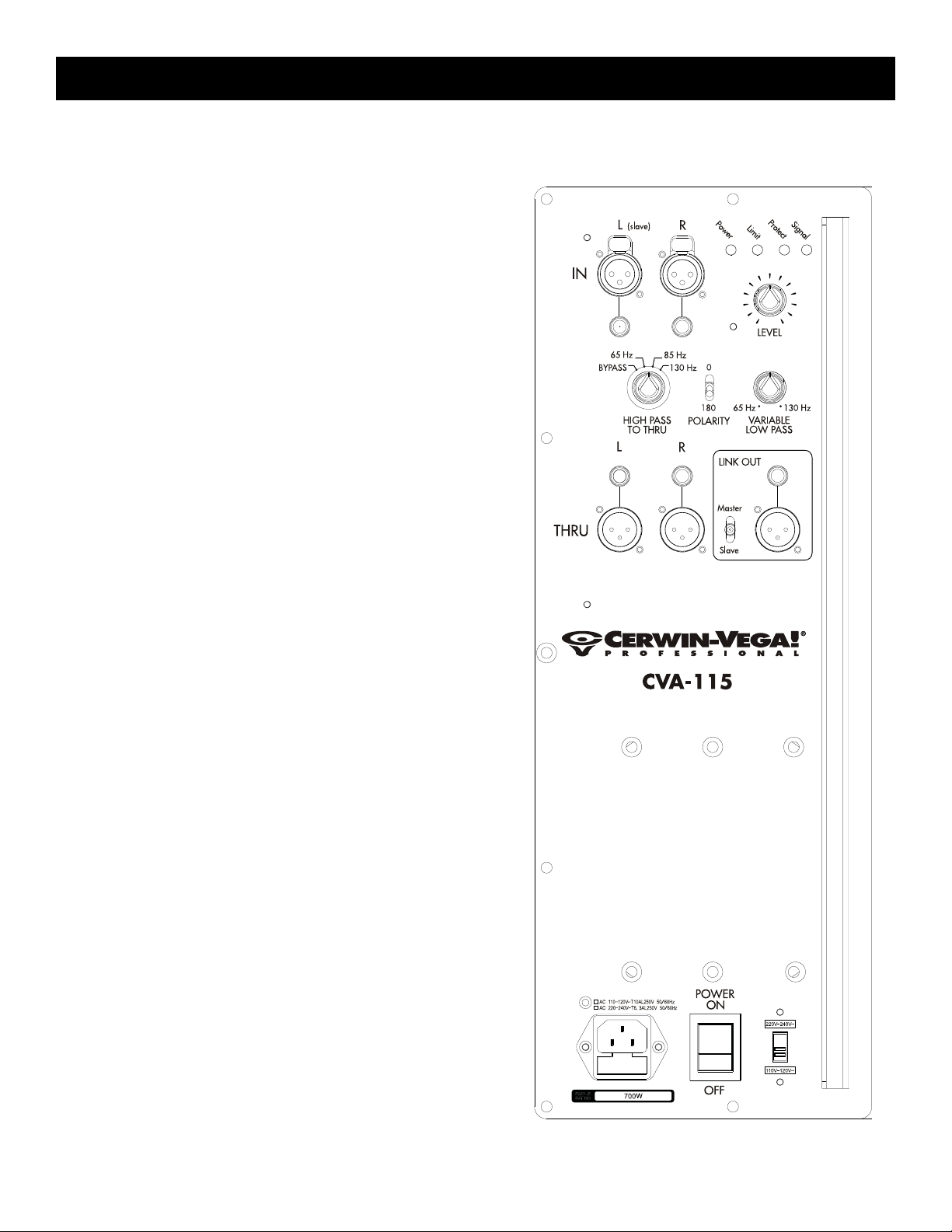
Back Panel Controls, Connectors and Indicators
INDICATORS: Illumination of LED indicates status of amplifier.
Power: Electric current is live and present in the system
Limit: This LED lights when the limiter is engaged to pre-
vent the amplifier from clipping. As a visual warning, it stays lit for a short period after the limiter has
turned off
Protect: The built-in amplifier has shut down to protect
itself
Signal: A line-level signal is present in the system
IN L & R inputs: Electronically balanced XLR and 1/4” phono
connectors accept input signal from line-level sources. IN L & R
also routes to THRU L & R outputs.
LEVEL: Controls the master volume at the pre-amp stage.
HIGH PASS FILTER: When sending a full range signal
through the subwoofer to top cabinet, the HPF blocks LF signals below
indicated frequencies from reaching the top cabinet.
VARIABLE LOW PASS FILTER: When sending a full range
signal to the subwoofer, the variable LPF blocks HF signals
above indicated frequencies from reaching the subwoofer.
THRU L & R outputs: Provide a loop-thru of the signals coming in on the L and R inputs. The High Pass filter is active on
these outputs. These outputs and the High Pass filter area
always active regardless of whether the unit is in master or
slave mode. Typically these outputs are used for top cabinets.
POLARITY SWITCH: Changes the polarity of the subwoofer,
also referred to as the “phase”. Listen and adjust for maximum
bass.
MASTER/SLAVE: This mode is used to provide the ability to
adjust multiple sub units from the master sub. When switched
to MASTER, all sub controls are functional and both L and R
inputs are operational. The LINK OUT connector sums the
input signals from both L and R inputs and is used to send a
signal to a sub in SLAVE mode. When set to SLAVE mode, only
the L input connector is active and the LEVEL, POLARITY, and
LOW PASS FILTER are inactive. To attach more subs, set them
to SLAVE mode, use the LINK OUT of the previous sub, and
send this signal to the L IN on the SLAVE.
LINK OUT: Used to send a signal to a sub set to SLAVE mode.
When the sub is set to SLAVE mode, the LINK OUT provides a
summed signal of the L and R inputs. (See MASTER/SLAVE for
more information.)
POWER SWITCH: Turns the AC power of the unit on and off.
AC INPUT: Input for attachment of the IEC power cord.
6
Manual_CVA115-A Originator: Tamera Hanna 1/24/2008 Size 8.5” x 11” Pages 20 (Fully Translated)
CERWIN-VEGA! PROFESSIONAL ACTIVE SERIES
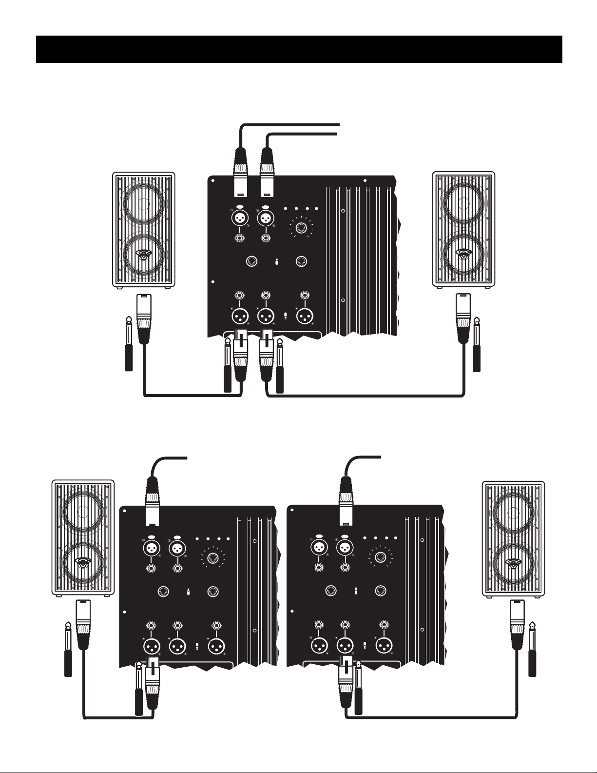
System Configurations
One Cerwin-Vega Active Subwoofer with Two Active Speakers
Cerwin-Vega! Active Sub
Protect
THRU
L
Power
R
IN
BYPASS
65 Hz
HIGH PASS
L
TO THRU
0
85 Hz
130 Hz
180
POLARITY
R
LINK OUT
Master
Signal
Limit
LEVEL
65 Hz
130 Hz
VARIABLE
LOW PASS
Slave
Bypass
From Mixer
Two Cerwin-Vega Active Subwoofers with Two Active Speakers
From Mixer
Cerwin-Vega! Active Sub #2
Protect
Power
Limit
LEVEL
65 Hz
130 Hz
VARIABLE
LOW PASS
LINK OUT
Master
Slave
THRU
From Mixer
Cerwin-Vega Active Sub #1
Protect
L
Power
R
IN
BYPASS
65 Hz
HIGH PASS
L
TO THRU
0
85 Hz
130 Hz
180
POLARITY
R
LINK OUT
Master
Signal
Limit
L
R
IN
LEVEL
65 Hz
VARIABLE
LOW PASS
130 Hz
BYPASS
65 Hz
HIGH PASS
L
TO THRU
0
85 Hz
130 Hz
180
POLARITY
R
THRU
Slave
Bypass
Signal
Bypass
 Loading...