

Cervis Warrior MCB-9XL User Manual

MCB-9XL Transmitters
™
U106.3.0
2019 Cervis, Inc.
MCB-9XL Transmitters
Cervis, Inc. reserves the right to change this manual or edit, delete, or modify any information without prior notification.
FCC Statements
Industry Canada Statement
radiofrequency-exposure-guidelines-environmental-workplace-health-health-canada.html.
Industry Canada Statement
si le brouillage est susceptible d'en compromettre le fonctionnement.
Industry Canada Unlicensed Devices EIRP Statements for Removable Antennas
supérieur au gain maximal indiqué, sont strictement interdits pour l'exploitation de l'émetteur.
This document is the property of Cervis, Inc. and cannot be copied, modified, e-mailed, or reproduced without the express
prior written consent of Cervis, Inc.
15.19 – Two Part Warning
This device complies with Part 15 of the FCC rules. Operation is subject to the following two conditions:
(1) This device may not cause harmful interference and
(2) This device must accept any interference received, including interference that may cause undesired operation.
15.21 – Unauthorized Modification
NOTICE: The manufacturer is not responsible for any unauthorized modifications to this equipment made by the user. Such modifications could
void the user’s authority to operate the equipment.
15.105(b) – Note:
This equipment has been tested and found to comply with the limits for a Class B digital device, pursuant to Part 15 of the FCC Rules. These
limits are designed to provide reasonable protection against harmful interference in a residential installation. This equipment generates, uses and
can radiate radio frequency energy and, if not installed and used in accordance with the instructions, may cause harmful interference to radio
communications. However, there is no guarantee that interference will not occur in a particular installation. If this equipment does cause harmful
interference to radio or television reception, which can be determined by turning the equipment off and on, the user is encouraged to try to
correct the interference by one or more of the following measures:
Reorient or relocate the receiving antenna.
Increase the separation between the equipment and receiver.
Connect the equipment into an outlet on a circuit different from that to which the receiver is connected.
This device complies with RSS-210 of Industry Canada.
The installer of this radio equipment must ensure that the antenna is located or pointed such that it does not emit RF field in excess of Health Canada limits
for the general population; consult Safety Code 6, obtainable from Health Canada’s website https://www.canada.ca/en/healthcanada/services/environmental-workplace-health/reports-publications/radiation/safety-code-6-health-canada-radiofrequency-exposure-guidelinesenvironmental-workplace-health-health-canada.html.
Le présent appareil est conforme à la norme CNR-210 d'Industrie Canada.
Le programme d’installation de cet équipement radio doit s’assurer que l’antenne est située ou fait telle qu’elle n’émet pas de champ RF dépassant les
limites de Santé Canada pour la population générale ; consulter le Code de sécurité 6, disponible auprès de Santé Canada site Web
https://www.canada.ca/en/health-canada/services/environmental-workplace-health/reports-publications/radiation/safety-code-6-health-canada-
This device complies with Industry Canada licence-exempt RSS standard(s). Operation is subject to the following two conditions: (1) this device may not
cause interference, and (2) this device must accept any interference, including interference that may cause undesired operation of the device.
Le présent appareil est conforme aux CNR d'Industrie Canada applicables aux appareils radio exempts de licence. L'exploitation est autorisée aux deux
conditions suivantes : (1) l'appareil ne doit pas produire de brouillage, et (2) l'utilisateur de l'appareil doit accepter tout brouillage radioélectrique subi, même
Part 1: Under Industry Canada regulations, this radio transmitter may only operate using an antenna of a type and maximum (or lesser) gain
approved for the transmitter by Industry Canada. To reduce potential radio interference to other users, the antenna type and its gain should be so
chosen that the equivalent isotropically radiated power (EIRP) is not more than that necessary for successful communication.
Partie 1 : Conformément à la réglementation d'Industrie Canada, le présent émetteur radio peut fonctionner avec une antenne d'un type et d'un gain maximal
(ou inférieur) approuvé pour l'émetteur par Industrie Canada. Dans le but de réduire les risques de brouillage radioélectrique à l'intention des autres
utilisateurs, il faut choisir le type d'antenne et son gain de sorte que la puissance isotrope rayonnée équivalente (p.i.r.e.) ne dépasse pas l'intensité
nécessaire à l'établissement d'une communication satisfaisante.
Part 2: This radio transmitter (LOBSRF-310) has been approved by Industry Canada to operate with the antenna type listed below with the
maximum permissible gain and required antenna impedance for each antenna type indicated. Antenna types not included in this list, having a
gain greater than the maximum gain indicated for that type, are strictly prohibited for use with this device.
Partie 2 : Cet émetteur radio (LOBSRF-310) a été approuvé par Industrie Canada pour fonctionner avec les types d'antenne énumérés ci-dessous et ayant
un gain admissible maximal et l'impédance requise pour chaque type d'antenne. Les types d'antenne non inclus dans cette liste, ou dont le gain est

User Manual
i
Table of Contents
Table of Contents .......................................................................................................................... i
List of Figures ............................................................................................................................... i
List of Tables ................................................................................................................................. i
Cervis, Inc. Safety Precautions .................................................................................................. ii
1.0 Warrior MCB-9XL Transmitter (MCB-9XL) ......................................................................... 1
2.0 Warrior MCB-9XL Layout .................................................................................................... 3
2.1 Standard Joysticks, Toggle Switches, and Pushbuttons ............................................. 3
2.2 LEDs ................................................................................................................................... 3
2.3 Neck/Shoulder Harness ................................................................................................... 4
2.3.1 Adjusting the Harness .................................................................................................. 5
2.3.2 Attaching the Harness to the MCB-9XL ....................................................................... 5
3.0 MCB-9XL Battery Installation .............................................................................................. 9
3.1 Low Battery and Auto Shutdown .................................................................................... 9
4.0 Warrior MCB-9XL Operation ............................................................................................. 10
4.1 MCB-9XL System Startup .............................................................................................. 10
4.2 Associating an MCB-9XL with a Receiver .................................................................... 11
4.2.1 Associating an MCB-9XL Using the DIP Switch Unlock Method. .............................. 11
4.2.2 Associate an MCB-9XL to a Receiver ........................................................................ 12
4.3 Adjusting MCB-9XL Inactivity Timeout ........................................................................ 15
4.4 Tilt Fault Mode................................................................................................................. 18
5.0 Warrior MCB-9XL Specifications ...................................................................................... 21
Appendix A: Exposure to Radio Frequency Energy .............................................................. 22
Appendix B: RF Exposure Considerations ............................................................................. 22
Appendix C: Agency Label........................................................................................................ 23
List of Figures
Figure 1. Warrior MCB-9XL Three- and Four-Joystick Transmitters ........................................ 1
Figure 2. MCB-9XL Battery Installation ........................................................................................ 9
Figure 3. MCB-9XL Turn ON/OFF................................................................................................ 10
Figure 4. Method 2 Virtual Unlock Switch S07 ─ Push and Hold Down .................................. 11
Figure 5. Warrior MCB-9XL Agency Label ................................................................................. 23
List of Tables
Table 1. MCB-9XL Standard Switches ......................................................................................... 3
Table 2. MCB-9XL LEDs ................................................................................................................. 3
Table 3. MCB-9XL Advanced LED Diagnostics ........................................................................... 3
Table 4. Warrior MCB-9XL Receiver Specifications ................................................................. 21
2019 Cervis, Inc.

Warrior MCB-9XL Transmitters
ii
Cervis, Inc. Safety Precautions
Read and follow all instructions.
Failure to abide by Safety Precautions may result in equipment failure, loss of
authority to operate the equipment, and personal injury.
Use and maintain proper wiring. Follow equipment manufacturer instructions.
Improper, loose, and frayed wiring can cause system failure, equipment damage, and
intermittent operation.
Changes or modifications made to equipment not expressly approved by the
manufacturer will void the warranty.
Equipment owner/operators must abide by all applicable Federal, State, and Local
laws concerning equipment installation and operation. Failure to comply could result
in penalties and could void user authority to operate the equipment.
Make sure that the machinery and surrounding area is clear before operating. Do not
activate the transmitter control system until certain that it is safe to do so.
Turn off the mini console box transmitter and remove power from the machine unit
before attempting any maintenance. This will prevent accidental operation of the
controlled machinery.
Use a damp cloth to keep units clean. Remove mud, concrete, dirt, etc. after use to
prevent obstructing or clogging the buttons, levers, wiring, and switches.
Do not allow liquid to enter the mini console box or machine unit enclosures. Do not
use high-pressure equipment to clean the mini console box transmitter or machine
unit. Liquid will damage the interior circuitry.
Disconnect the radio machine unit before welding on the machine. Failure to
disconnect the machine unit may result in destruction of or damage to the machine
unit.
Operate and store units only within the specified operation and storage temperatures
defined in this document’s specifications.
Keep high-energy radio frequency (RF) devices away from mini console box
transmitters. Activating high-power communication radios, for instance, in close
proximity to mini console box transmitters can cause interference and “false” circuit
activation.
Do not key two-way radios while using the mini console box transmitter.
U106.3.0
User Manual
1
S09 Start/Horn/MLC
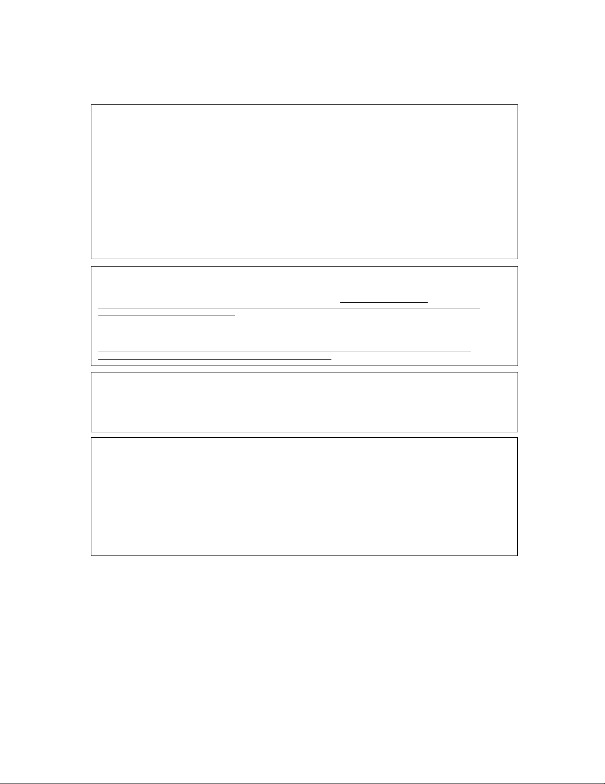
1.0 Warrior MCB-9XL Transmitter (MCB-9XL)
The Warrior MCB-9XL transmitter is a compact remote control unit that interfaces with Warrior
machine unit (MU) receivers. The MCB-9XL is available as either a three-joystick- or fourjoystick transmitter, both powered by four type “AA” cell batteries. Each version includes two
toggle switches, a push-pull Single-Pole/Single-Throw (SPST) Professional STOP switch, and a
green multi-purpose pushbutton. Both MCB-9XL designs have four red diagnostic/status LightEmitting Diodes (LEDs) that indicate wireless link (or radio frequency, “RF”) activity, Battery
(“Bat.”) condition, trolley/hoist “A” selection, and trolley/hoist “B” selection. The rugged MCB-9XL
enclosure is made of glass-filled nylon designed to meet an IP55 ingress protection rating, as
defined by IEC 60529.
Using line-of-sight Direct Sequence Spread Spectrum (DSSS) technology, the mini console
box’s (MCB’s) transmission power permits a generous control distance in crowded radio
environments. The rugged enclosure and water-resistant switches and joysticks ensure reliable
operation in harsh weather environments – operating in temperatures as low as -4°F (-20°C) to a
maximum of 158°F (70°C). Warrior MCBs transmit RF signals via an internal antenna, while
status is conveyed to the user via the four LEDs.
MCB-9XL transmitter functions can be configured by manipulating the MU receiver DIP Switch
(S01) mode settings.
Figure 1. Warrior MCB-9XL Three- and Four-Joystick Transmitters
Warrior MU-9X15 Features
Three or Four 2-Step, Single-Axis Joysticks
Two Toggle Switches and an Activate Pushbutton
900MHz @ 100mW Operation
Push/Pull Professional Stop Switch
Four System Status/Diagnostics LEDs
2019 Cervis, Inc.

Warrior MCB-9XL Transmitters
2
Operates Using Four “AA” Cell Batteries
Mounting by Custom Shoulder Harness
U106.3.0
User Manual
3
Switch
Function
Type
Switch Type/Description
JS1 through JS4
Trolley/Hoist Motion
Control
Analog Joystick
Single-axis, Two-step
S01
A/B Select
Toggle
Three-Position Maintained
S07
Aux/Select/Next
Toggle
Three-Position Momentary
S09
Horn/Start/ON
Pushbutton
Green, SPST
STOP
STOP
2-Position Maintained
Pull up to ENABLE;
Push down to STOP
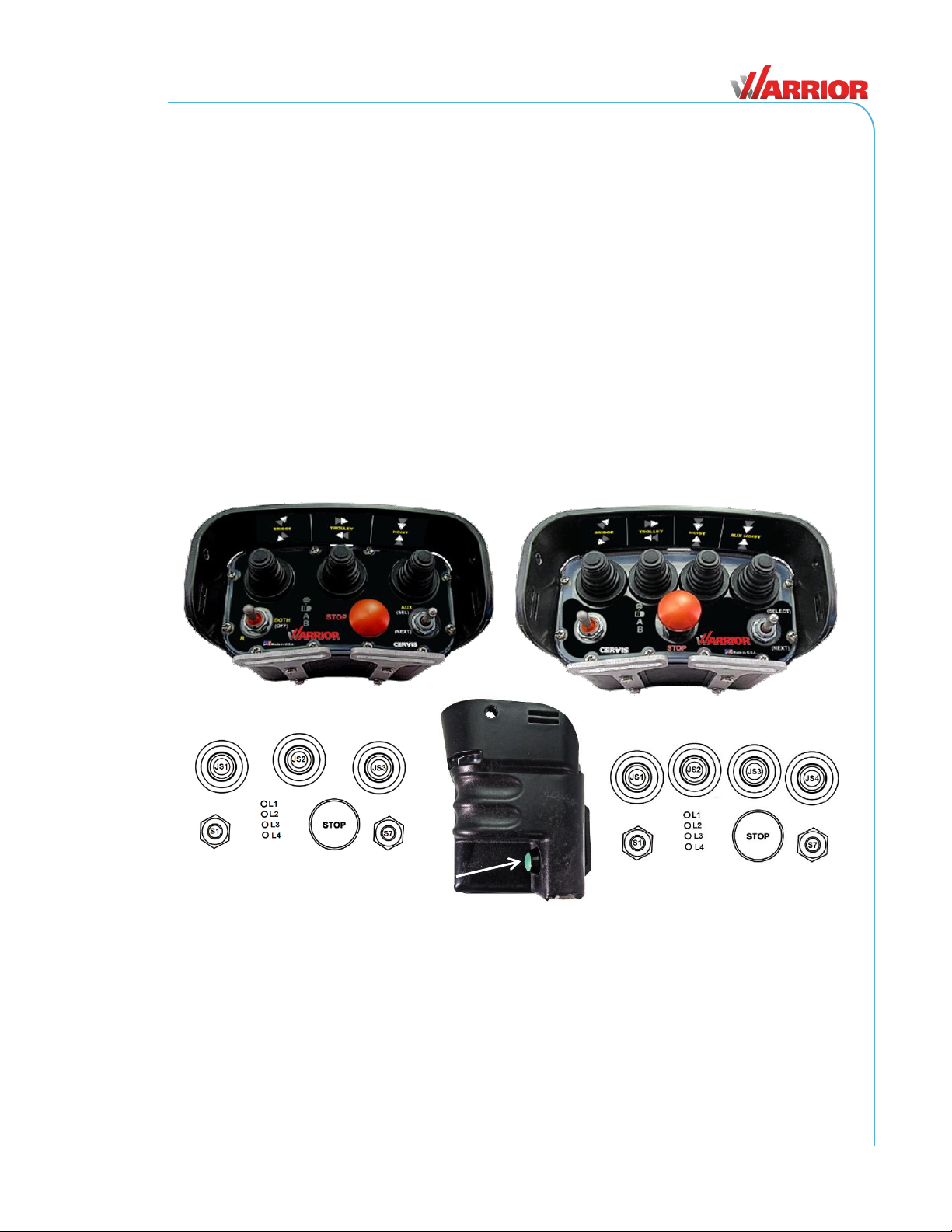
LED
Icon
Function
Action
L1
Transmit indication (radio
frequency or “RF”)
Flashes when message is sent
Solid with switch motion
L2
Low Battery indication (“Bat.”)
Slow Blinks when <2.2V
L3
A Selection
Lights when A trolley/hoist is selected
L4
B Selection
Lights when B trolley/hoist is selected
LEDs
Indication
Diagnostic
RF
RF Solid
Transmitting, looking for receiver.
RF Blinking
Transmitting to and receiving from the mounted receiver.
Bat
RF/A ↔ Bat/B
↔
M-Stop Check: Cycle M-Stop, Blinks back-and-forth.
2.0 Warrior MCB-9XL Layout
2.1 Standard Joysticks, Toggle Switches, and Pushbuttons
Table 1 lists the standard MCB-9XL switches.
Table 1. MCB-9XL Standard Switches
2.2 LEDs
Table 2 lists the MCB-9XL LEDs. Table 3 lists advanced LED diagnostic functions.
Table 2. MCB-9XL LEDs
Table 3. MCB-9XL Advanced LED Diagnostics
2019 Cervis, Inc.
Warrior MCB-9XL Transmitters
4
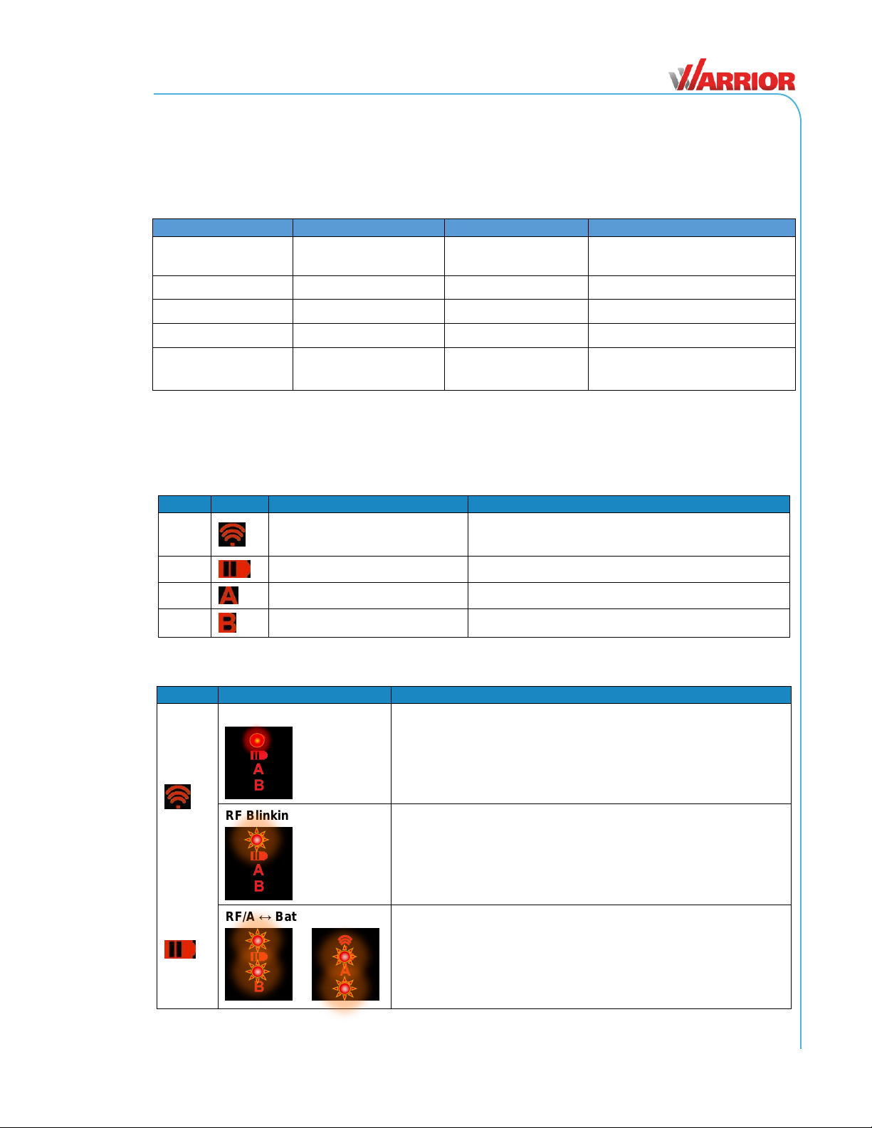
LEDs
Indication
Diagnostic
RF/Bat ↔ A/B
↔
Stuck switch: Check switches/proportional not neutral.
RF→Bat→A→B→RF→Bat
Scrolling: Tilt Mode active.
B→A→Bat→RF→B
Scrolling: Signifies Maintenance Mode
Bat
Blinking: Batteries low, replace with fresh batteries soon.
Select
RF/BAT/A/B
Shutting Off: Unit is shutting down:
Inactivity timeout
M-Stop engaged
Keyswitch moved to OFF
Unit wake-up without switch S12
Select
Bat
Shutting Off: Batteries below operating level; unit shutting down;
replace batteries with fresh set.
A/B
Shutting Off: Joystick/Lever command reached out-of-bounds.
Condition unsafe, operation turning off.
2.3 Neck/Shoulder Harness
The 1¾" wide neck/shoulder harness lets you conveniently and comfortably strap the MCB-9XL
around your neck or shoulder for easy access and operation. Adjustable to lengths up to 60
inches (~1.5m), the harness conforms to most body lengths; and its rugged, heavy-duty
construction and quick-release fasteners keep a single MCB-9XL securely against your body.
Plus, its polypropylene webbing resists wear, and its bright orange color gives it high visibility
against even the lightest colored garments.
U106.3.0
User Manual
5
2.3.1 Adjusting the Harness
Before you attach the harness to your MCB-9XL, adjust the blue strap to the most comfortable
operating length for your individual body type.
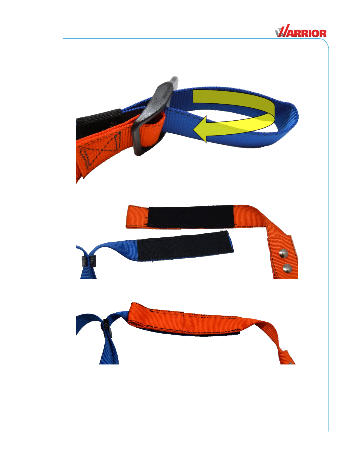
The harness’ left strap features a 6" (152mm) long quick release hook-and-loop Nylon rip cord.
Connect the two parts of the rip cord together, and press down to secure the connection.
2.3.2 Attaching the Harness to the MCB-9XL
Both ends of the high-visibility orange straps feature a pair of heavy-duty metal button snaps at
the ends.
2019 Cervis, Inc.
 Loading...