

Cervis SBU900, SHH900 User Manual

SmaRT 902
Remote Control System
Manual
U007.0-SmaRT902_system-R
It2 ©2007 Cervis, Inc.

SmaRT Remote Control System
This document is the property of Cervis, Inc. and cannot be copied, modified,
or reproduced without the express prior written consent of Cervis, Inc.
Cervis, Inc. reserves the right to change this manual or edit, delete, or modify
any information without prior notification.
FCC Statements
15.19 – Two Part Warning
This device complies with Part 15 of the FCC rules. Operation is subject to the following two conditions:
(1) This device may not cause harmful interference and
(2) This device must accept any interference received, including interference that
may cause undesired operation.
15.21 – Unauthorized Modification
NOTICE: The manufacturer is not responsible for any unauthorized modifications to
this equipment made by the user. Such modifications could void the user’s authority
to operate the equipment.
Cervis, Inc.
Visit our Web site at: www.cervisinc.com
© 2007 Cervis, Inc. All rights reserved. Content is subject to change without notice.

User Manual
Contents
FCC Statements ............................................................................................................................ i
1.0 SmaRT 902 Remote Control System.................................................................................. 1
1.1 Features............................................................................................................................. 1
1.2 PT0-902 Handheld Remote .............................................................................................. 2
1.3 BU-902F Base Unit............................................................................................................ 2
1.4 Communication Configuration Options ......................................................................... 3
1.4.1 Associate Handheld to Base Unit Procedure...............................................................3
1.4.2 Disassociate Handheld to Base Unit Procedure.......................................................... 4
2.0 Handheld Battery Installation or Change .......................................................................... 6
3.0 Base Unit Installation ..........................................................................................................7
4.0 Using the SmaRT PTO-902 Handheld Remote.................................................................. 8
To operate the system:................................................................................................................ 8
5.0 Wiring Harness..................................................................................................................... 9
6.0 Specifications..................................................................................................................... 10
6.1 Handheld.......................................................................................................................... 10
6.2 Base Unit ......................................................................................................................... 11
Figures
Figure 1. PTO-902 Handheld Remote and BU-902F Base Unit..................................................1
Figure 2. PTO-902 (without bumper)............................................................................................2
Figure 3. Female Twelve (12) Pin Connector...............................................................................3
Figure 4. BU-902F LEDs ................................................................................................................3
Figure 5. Handheld PTO Buttons..................................................................................................4
Figure 6. Handheld Battery Installation .......................................................................................6
Figure 7. Base Unit.........................................................................................................................7
Figure 8. Wiring Harness Cable....................................................................................................7
Figure 9. PTO-902 Front Panel Buttons and Diagnostic LEDs..................................................8
Tables
Table 1 - Handheld Specifications..............................................................................................10
Table 2 - Base Unit Specifications..............................................................................................11
©2007 Cervis, Inc.
i

SmaRT 902 Remote Control System
Notes:
U007.0-SmaRT902_system-R
ii
Product Name
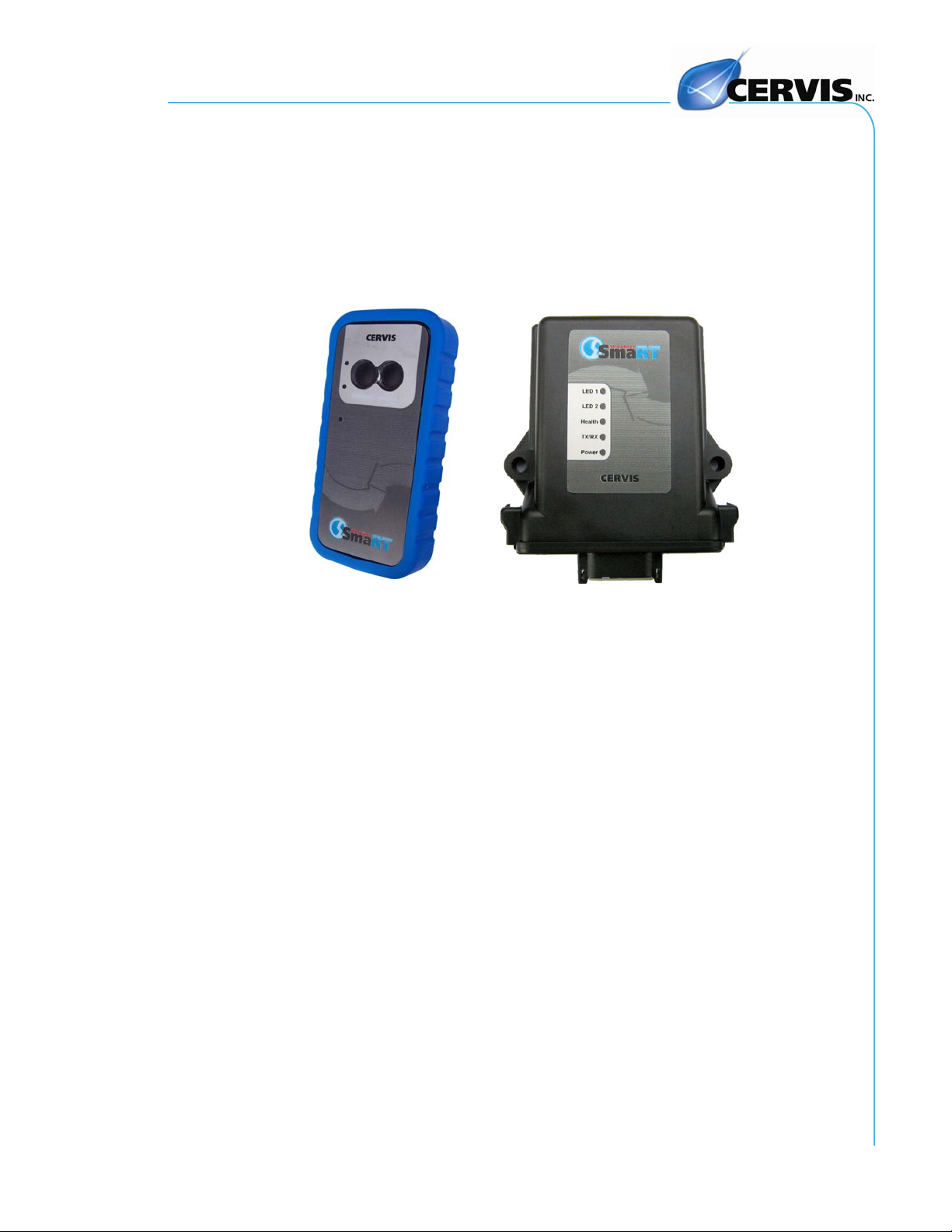
1.0 SmaRT 902 Remote Control System
The standard SmaRT 902 Remote Control System consists of a 2-button PTO-902
wireless handheld transmitter, a BU-902F base unit, and the wiring harness that is used
to connect the base unit to the controlled apparatus. A single base unit is capable of
communicating with up to eight PTO-902 Handheld units. The rugged construction,
compact size, and multiple output versatility allow for SmaRT Systems to be used for
many applications that require remote operation.
Figure 1. PTO-902 Handheld Remote and BU-902F Base Unit
1.1 Features
• IP65 Enclosure
• Operating Temp: -20°C to +55°C
• Storage Temp: -40°C t o +85°C
• PTO-902 Handheld has two Push-to-Operate (PTO) buttons
• Handheld powered by t hree AAA Batteries (+3.6VDC to 4.5 VDC)
• Base Unit +9VDC to +1 6VDC Input Power
• Two FET high side switching outputs (8A max.)
• License Free Frequency, 900MHz Spread Spectrum Technology
• 300’ (100m) Range
• Rugged high-impact polymer enclosure
• Remo vable rubber bumper (handheld)
• Lanyard
• Compact W eatherproof Design
• Five base unit and three handheld diagnostic LEDs
• Single connector interface for ease of wiring
©2007 Cervis, Inc.
1
SmaRT 902 Remote Control System
K
–
1.2 PT0-902 Handheld Remote
The SmaRT PTO-902 Handheld Remote features a 300’ handheld-to-base unit communication range providing two function press-to-operate (PTO) control. Using direct
sequence spread spectrum (DSSS) wireless technology at 900MHz, the handheld unit
provides a robust link with a base unit in congested radio environments. SmaRT hand-
held units feature seamless association to a SmaRT BU-902F Base Unit without the
need to open either case.
The handheld enclosure is constructed of rugged high-impact polymer with a polycarbonate face plate securely sealed and attached by eight screws. It is further protected
by a removable rubber bumper that covers the back and sides of the unit extending beyond the recessed faceplate. A convenient lanyard that attaches to the remote is provided.
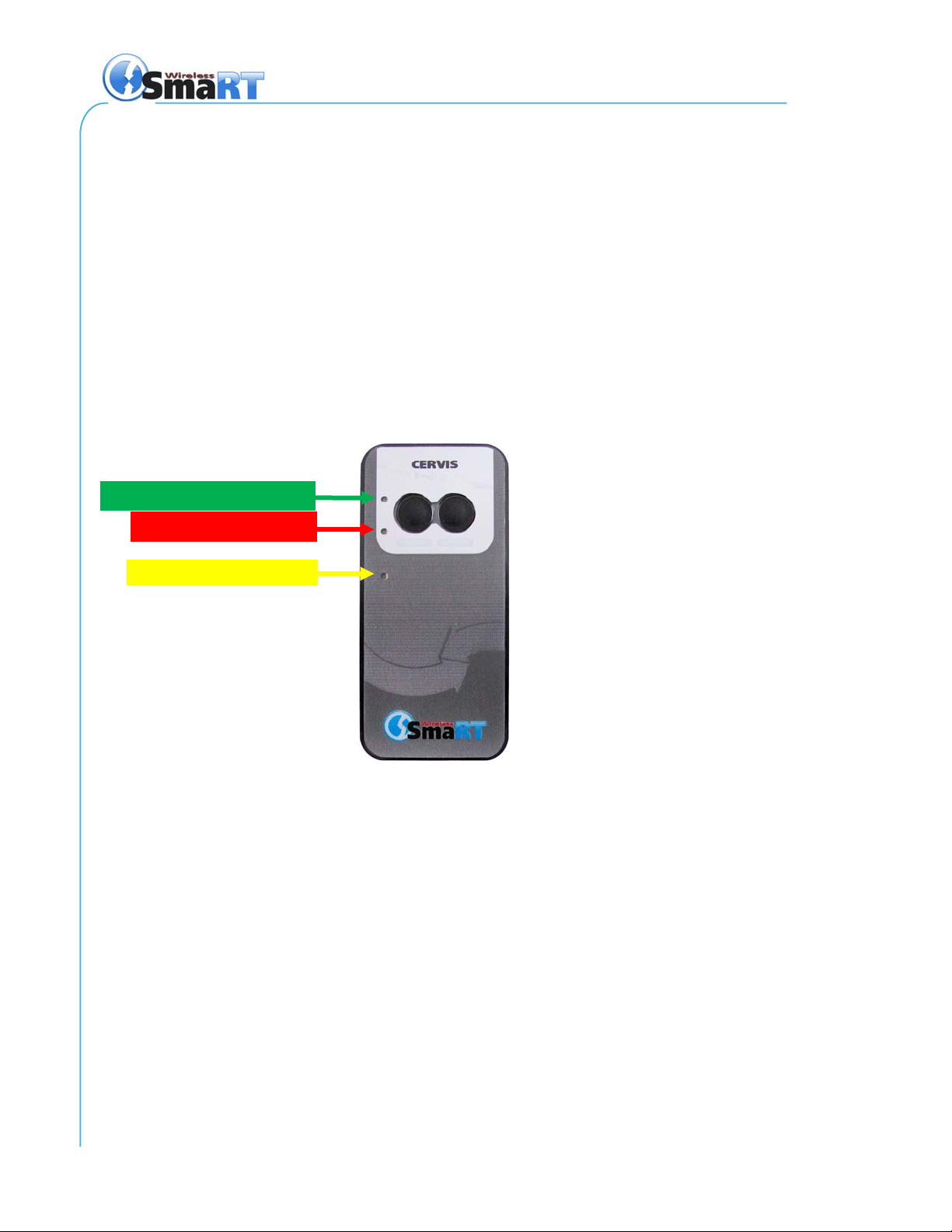
The handheld is powered by three size AAA batteries. Three status/diagnostic LEDs
are visible on the handheld faceplate as shown in Figure 2 below.
TX – Green when transmitting
RX – Red when receiving
LIN
Yellow while linking
Figure 2. PTO-902 (without bumper)
1.3 BU-902F Base Unit
The SmaRT BU-902F Base Unit features two FET, 8A max high-side switching outputs.
It accepts an input power operating voltage range from +9 to +16VDC. Using Direct Sequence Spread Spectrum (DSSS) wireless technology at 900MHz, the base unit provides a robust link with a handheld in congested radio environments
SmaRT base units feature seamless association to a SmaRT handheld unit without the
need to open either the remote or base unit case. All controlled apparatus connections
to the base unit are made via a single cable.
The base unit compact enclosure is constructed of rugged, heavy duty high impact
plastic—the type commonly used by the automotive industry. VDC power to the unit
and output signals are ported via the heavy duty twelve (12) pin automotive-type connector.
U007.0-SmaRT902_system-R
2
 Loading...