

Cervis MCB Series, MCB-9H02JS, MCB-9H02JS-UMB, MCB-9H04JS-UMB, MCB-9H04JS User Manual
...
Mini Console Box Remote
MCB User Manual
™
U092.1.1
2019 Cervis, Inc.
SmaRT MCB
Cervis, Inc. reserves the right to change this manual or edit, delete, or modify any information without prior notification.
FCC Statements
Connect the equipment into an outlet on a circuit different from that to which the receiver is connected.
Industry Canada Statement
environmental-workplace-health-health-canada.html.
Industry Canada Statement
susceptibles de causer un fonctionnement non désiré de l'appareil.
IC Unlicensed Devices EIRP Statements for Removable Antennas
appareil un type d'antenne ne figurant pas dans cette liste ou ayant un gain supérieur au gain maximum indiqué pour ce type.
RoHS Compliance Statement
Phone: 724.741.9000 Fax: 724.741.9001
This product may contain material that may be hazardous to human health and the environment. In
compliance with EU Directive 2002/96/EC on Waste Electrical and Electronic Equipment (WEEE):
This product may be returnable to the distributor for recycling. Contact your distributor
This document is the property of Cervis, Inc. and cannot be copied, modified, e-mailed, or reproduced without the express
prior written consent of Cervis, Inc.
15.19 – Two Part Warning
This device complies with Part 15 of the FCC rules. Operation is subject to the following two conditions:
(1) This device may not cause harmful interference and
(2) This device must accept any interference received, including interference that may cause undesired operation.
15.21 – Unauthorized Modification
NOTICE: The manufacturer is not responsible for any unauthorized modifications to this equipment made by the user. Such modifications could
void the user’s authority to operate the equipment.
15.105(b) – Note:
This equipment has been tested and found to comply with the limits for a Class B digital device, pursuant to Part 15 of the FCC Rules. These
limits are designed to provide reasonable protection against harmful interference in a residential installation. This equipment generates, uses and
can radiate radio frequency energy and, if not installed and used in accordance with the instructions, may cause harmful interference to radio
communications. However, there is no guarantee that interference will not occur in a particular installation. If this equipment does cause harmful
interference to radio or television reception, which can be determined by turning the equipment off and on, the user is encouraged to try to
correct the interference by one or more of the following measures:
Reorient or relocate the receiving antenna.
Increase the separation between the equipment and receiver.
This device complies with Canadian RSS-210.
The installer of this radio equipment must ensure that the antenna is located or pointed such that it does not emit RF field in excess of Health Canada limits
for the general population; consult Safety Code 6, obtainable from Health Canada’s website https://www.canada.ca/en/health-
canada/services/environmental-workplace-health/reports-publications/radiation/safety-code-6-health-canada-radiofrequency-exposure-guidelinesenvironmental-workplace-health-health-canada.html.
Le présent appareil est conforme à la norme CNR-210 d'Industrie Canada.
L'installateur de cet équipement radio doit s'assurer que l'antenne est située ou orientée de façon à ne pas émettre un champ RF dépassant les limites de
Santé Canada pour la population générale; consulter le Code de sécurité 6, disponible sur le site Web de Santé Canada https://www.canada.ca/en/health-
canada/services/environmental-workplace-health/reports-publications/radiation/safety-code-6-health-canada-radiofrequency-exposure-guidelines-
This device complies with Industry Canada licence-exempt RSS standard(s). Operation is subject to the following two conditions: (1) this device may not
cause interference, and (2) this device must accept any interference, including interference that may cause undesired operation of the device.
Le présent appareil est conforme aux CNR d'Industrie Canada applicables aux appareils radio exempts de licence. Le fonctionnement est soumis aux deux
conditions suivantes : (1) cet appareil ne doit pas causer d'interférences, et (2) cet appareil doit accepter toute interférence, y compris les interférences
Part 1: Under Industry Canada regulations, this radio transmitter may only operate using an antenna of a type and maximum (or lesser) gain
approved for the transmitter by Industry Canada. To reduce potential radio interference to other users, the antenna type and its gain should be so
chosen that the equivalent isotropically radiated power (e.i.r.p.) is not more than that necessary for successful communication.
Partie 1 : Conformément à la réglementation d'Industrie Canada, le présent émetteur radio peut fonctionner avec une antenne d'un type et d'un gain maximal
(ou inférieur) approuvé pour l'émetteur par Industrie Canada. Dans le but de réduire les risques de brouillage radioélectrique à l'intention des autres
utilisateurs, il faut choisir le type d'antenne et son gain de sorte que la puissance isotrope rayonnée équivalente (p.i.r.e.) ne dépasse pas l'intensité
nécessaire à l'établissement d'une communication satisfaisante.
Part 2: This radio transmitter (LOBSRF-305 or LOBSRF-309) has been approved by Industry Canada to operate with the antenna type listed below
with the maximum permissible gain and required antenna impedance for each antenna type indicated. Antenna types not included in this list,
having a gain greater than the maximum gain indicated for that type, are strictly prohibited for use with this device.
Partie 2 : Cet émetteur radio (LOBSRF-305 ou LOBSRF-309) a été approuvé par Industrie Canada pour fonctionner avec le type d'antenne indiqué cidessous avec le gain maximal admissible et l'impédance d'antenne requise pour chaque type d'antenne indiqué. Il est strictement interdit d'utiliser avec cet
Cervis, Inc. complies with the requirements of Restriction of Hazardous Substances (RoHS/WEEE) Specification based on in-house practice and
declaration of compliance from our vendors. For additional information concerning RoHS compliance, please contact Cervis, Inc. at:
170 Thorn Hill Road Warrendale, PA 15086
Do not dispose of the product as unsorted municipal waste.
This product should be recycled in accordance with local regulations. Contact local
authorities for detailed information.
for details.
CERVIS, Inc.

User Manual
i
Table of Contents
Table of Contents .......................................................................................................................... i
List of Figures ............................................................................................................................... i
List of Tables ................................................................................................................................. i
Cervis, Inc. Safety Precautions ................................................................................................. iii
1.0 Introduction .......................................................................................................................... 1
2.0 Mini Console Box Layout .................................................................................................... 4
2.1 Standard Joysticks, Toggle Switches, and Pushbuttons ............................................. 4
2.2 LEDs ................................................................................................................................... 4
2.3 Optional Mini Console Box Umbilical Connection ........................................................ 6
2.4 Neck/Shoulder Harness ................................................................................................... 6
2.4.1 Adjusting the Harness .................................................................................................. 6
2.4.2 Attaching the Harness to the MCB ............................................................................... 7
3.0 Mini Control Box Battery ................................................................................................... 11
3.1 Battery Installation and Replacement .......................................................................... 11
3.2 Low Battery and Auto Shutdown .................................................................................. 11
4.0 MCB ON/OFF ...................................................................................................................... 12
5.0 MCB Associate Mode......................................................................................................... 13
6.0 MCB Joystick Adjustments ............................................................................................... 15
6.1 Enter Adjust Mode .......................................................................................................... 15
6.2 Low End Calibration (Min) ............................................................................................. 16
6.3 High End Calibration (Max) ............................................................................................ 16
6.4 To Abandon Adjust Mode .............................................................................................. 16
6.5 Exit Adjust Mode ............................................................................................................. 16
7.0 MCB Product Family Listing ............................................................................................. 18
8.0 Mini Console Box Specifications ..................................................................................... 19
Appendix A: Exposure to Radio Frequency Energy .............................................................. 20
Appendix B: Agency Identification Label Locations .............................................................. 20
Appendix C: Declaration of Conformity for MCB-2H0xJS ..................................................... 21
List of Figures
Figure 1. MCB-xH04JS Mini Console Box Example ................................................................... 2
Figure 2. Standard Console Box Can Umbilical .......................................................................... 6
Figure 3. MCB-9H02JS Battery Installation ............................................................................... 11
Figure 4. Turn MCB On and Off .................................................................................................. 12
Figure 5. MCB Switch Actuation for Associate Mode .............................................................. 13
Figure 6. Enter Adjust Mode ....................................................................................................... 15
Figure 7. Agency Identification Label Locations ...................................................................... 20
Figure 8. Declaration of Conformity for MCB-2H0xJS ............................................................. 21
List of Tables
Table 1. Mini Console Box Switches ............................................................................................ 4
Table 2. Mini Console Box LEDs .................................................................................................. 4
Table 3. Common MCB Product Family Features ..................................................................... 18
2019 Cervis, Inc.

SmaRT MCB
ii
Table 4. MCB Model Specific Features ...................................................................................... 18
Table 5. MCB Specifications ....................................................................................................... 19
U092.1.1

User Manual
iii
Cervis, Inc. Safety Precautions
Read and follow all instructions.
Failure to abide by Safety Precautions may result in equipment failure, loss of
authority to operate the equipment, and personal injury.
Use and maintain proper wiring. Follow equipment manufacturer instructions.
Improper, loose, and frayed wiring can cause system failure, equipment damage, and
intermittent operation.
Changes or modifications made to equipment not expressly approved by the
manufacturer will void the warranty.
Equipment owner/operators must abide by all applicable Federal, State, and Local
laws concerning equipment installation and operation. Failure to comply could result
in penalties and could void user authority to operate the equipment.
Make sure that the machinery and surrounding area is clear before operating. Do not
activate the remote control system until certain that it is safe to do so.
Turn off the handheld remote and remove power from the base unit before attempting
any maintenance. This will prevent accidental operation of the controlled machinery.
Remove power from a base unit either by detaching the 12-pin cable(s) from the base
unit connectors or by removing the source power from the circuit.
Use a damp cloth to keep units clean. Remove mud, concrete, dirt, etc. after use to
prevent obstructing or clogging the buttons, joysticks, wiring, and switches.
Do not allow liquid to enter the handheld or base unit enclosures. Do not use high-
pressure equipment to clean the handheld remote or base unit.
Disconnect the radio base unit before welding on the machine. Failure to disconnect
the base unit may cause destruction of or damage to the base unit.
Operate and store units only within the specified operation and storage temperatures
defined in this document’s specifications.
Keep high-energy radio frequency (RF) devices away from handheld remotes.
Activating high-power communication radios—for instance—in close proximity to
handheld remotes can cause interference and “false” circuit activation.
Do not key two-way radios while using the handheld remote.
2019 Cervis, Inc.


User Manual
1
1.0 Introduction
This manual guides users in the SmaRT™ Mini Console Box Remote’s (commonly referred to as
the “MCB”) general use and practices. Because of the extensive amount of options available and
the numerous possible standard and custom configurations, creating a single general user
manual that includes all possible configurations is impractical. However, this manual describes
standard configuration features including:
Switch and joystick positions.
Common procedure for setting up the communications link between remotes and base
units (Associate).
Pulse Width Modulation (PWM) joystick/potentiometer calibrations.
The standard MCB switch and joystick options include those illustrated with the example in
Figure 1.
Note: Documents included with the SmaRT system when it is sent to you include an MCB’s
specific operational details.
2019 Cervis, Inc.
SmaRT MCB
2
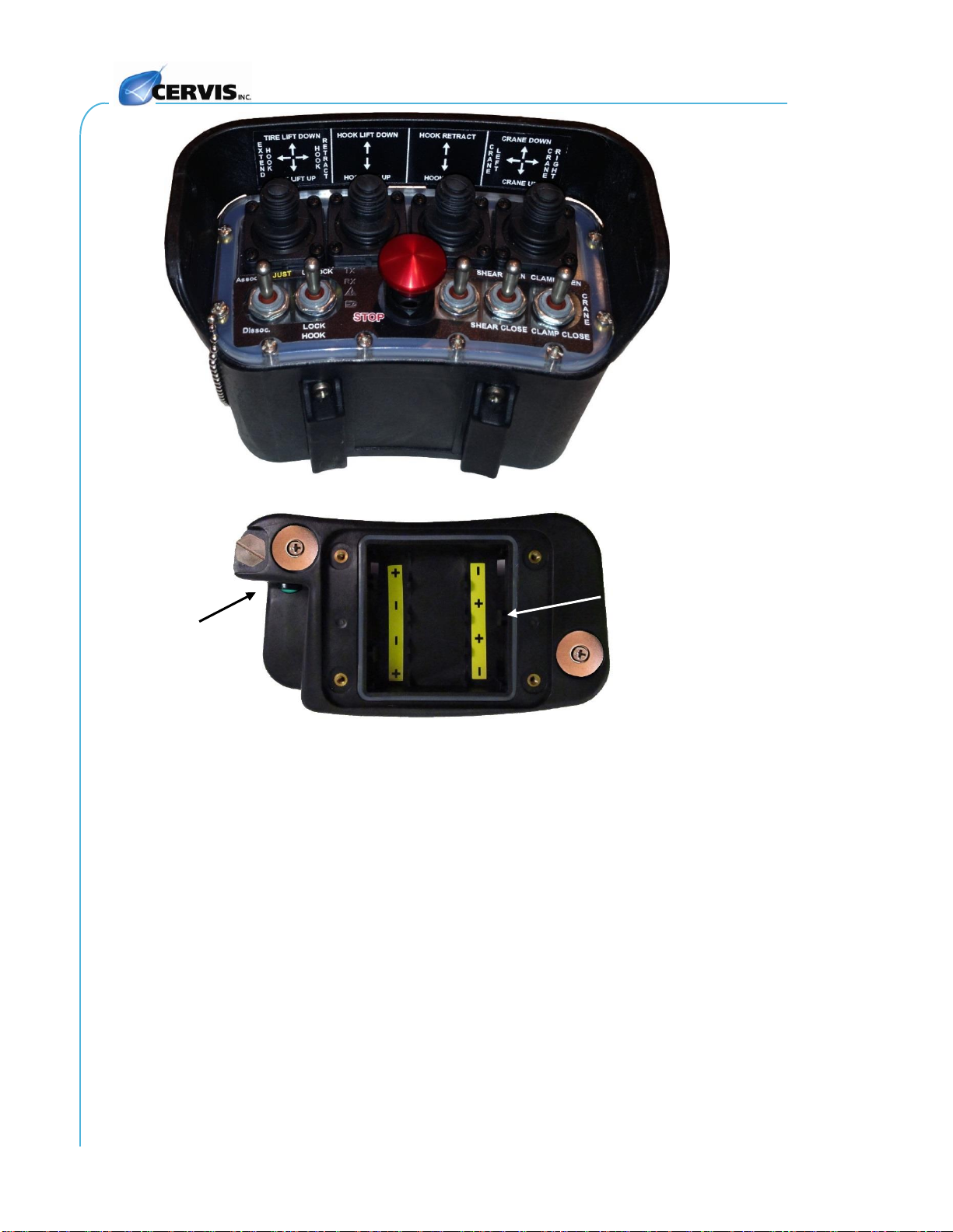
PB
Power Button
S9
Battery
Compartment
(cover removed)
Magnet
Magnet
Figure 1. MCB-xH04JS Mini Console Box Example
U092.1.1

User Manual
3
SmaRT MCBs communicate with and control a variety of SmaRT base units in either the
900MHz or 2.4GHz frequency ranges. MCB frequency range options are:
906–924MHz @ 10mW (900MHz)
2405–2480 MHz @ 100mW (2.4GHz)
Using line-of-sight Direct Sequence Spread Spectrum (DSSS) technology, both broadcast
ranges offer a generous control distance in crowded radio environments. Plus, neither broadcast
range requires a license for use. The rugged enclosure and water-resistant components ensure
reliable operation in harsh weather environments and temperatures as low as -20°C (-4°F) and
as high as 55°C (131°F). Standard SmaRT mini console boxes broadcast using an internal
antenna. You can also connect a Control Area Network (CAN) Bus umbilical cable to a base unit
when the MCB is engineered to do so. Users receive setup and operation status via a bank of
four Light-Emitting Diodes (LEDs).
Custom Versatility
The SmaRT Mini Console Box offers a variety of factory configured joystick and switch options.
Joystick choices range from one to four single or dual-axis bi-directional (per plane of operation)
joysticks for digital or proportional control. The MCB can have up to five (5) toggle switches with
the possibility of six toggle switches at the expense of a joystick position. As previously
mentioned, Cervis, Inc. also offers the choice of a CAN communication connector for use with an
umbilical cable for backup control.
MCB (Mini Console Box) Features
Four Dual- or Single-Axis Joysticks for Proportional or Digital Control
Five Toggles or Optional Button Controls (Custom Optional Six Toggles Available)
900MHz @ 10mW or 2.4GHz @ 100mW Operation
Push/Pull Professional Machine Stop Button
Four System Status/Diagnostic LEDs
CAN Umbilical Connection Available
Operates Using Four AA Cell Batteries
Magnets for Convenient Attachment to Ferrous Surfaces
Belt Loops to Securely Attach to Belt or Harness
Note: When using four joysticks, only three of the four joysticks can be used as dual-axis; the
fourth is limited as a single-axis control function.
2019 Cervis, Inc.
 Loading...