

Page 1

AB08 Tri Extension Mount Assembly
Page 2
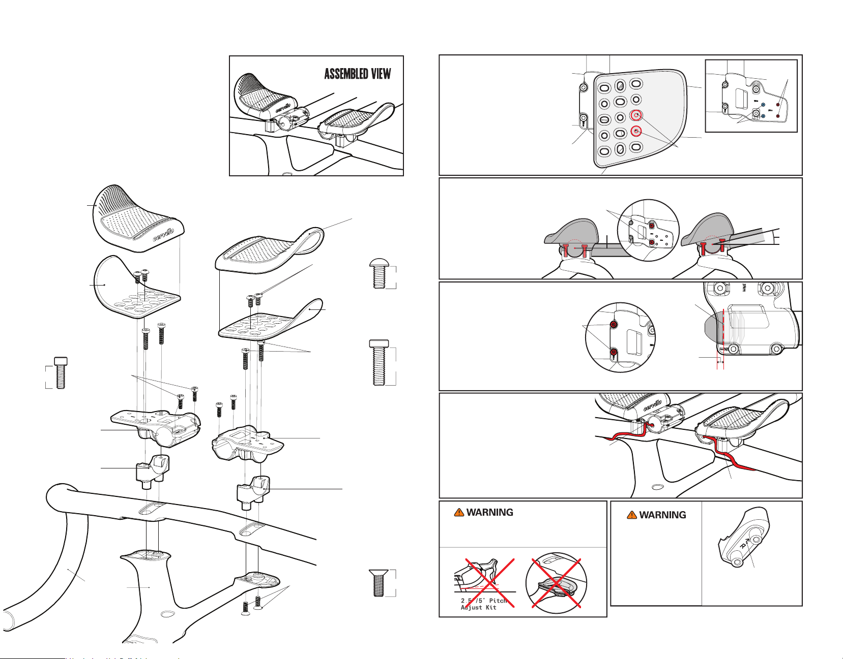
AB08 TRI EXTENSION
MOUNT ASSEMBLY
HBP-AB08-EXTMT
ADJUSTING THE PAD POSITION
Use the Pad Mounting Screws to
adjust position of the Arm Pad
Carriers.
Once desired angle is found, torque
the bolts to 3Nm.
The fixing screws must be installed
in fore-aft fixing position, and not
diagonal.
Narrow Setting
Pad Mounting
Screws
Wide
Setting
EX11 Arm Pad
Left
EX11 Arm Pad
Carrier
Left
Extension
12mm
Extension Mount
Upper
Left
Extension Mount
Base
Left
Clamping Screws
M4x0.7x12 SHCS LP
Qty:4
EX11 Arm Pad
Pad Mounting
M5x0.8x12 BHCS LT
M5x0.8x20 SHCS LP
Screws
Qty:4
EX11 Arm Pad Carrier
Upper to Base
Mounting Screws
Qty:4
Extension Mount Upper
Extension Mount
Right
12mm
Right
20mm
Right
Base Right
ADJUSTING THE TILT
Use the Upper Mounting
bolts to adjust the tilt of the
extension and pads
anywhere from 0-15 degrees.
Once desired angle is found,
torque the bolts to 3Nm.
EXTENSION POSITIONING
Secure the extensions by
tightening Extenstion
Clamping bolts to 3Nm.
If cutting the extensions,
ensure that there is NO MORE
THAN 5MM inside the rear edge
of the mount upper.
E-WIRE ROUTING
If extension shifters are used,
route E-wire through the back of
the extension and into the slot
on the back of the mount base.
Ensure that the extensions end at
the minimum cut line.
Upper Mounting
Bolts
Extension
Clamping
Bolts
Tuck cable
into slot on
mount upper.
0°
Minimum
Cut
Line
5MM
Tuck cable into rear
slot on mount base.
15°
Note: Bar and
Stem not included
in assembly
Handlebar
Mounting Screws
M5 x 0.8 x 14 FHCS TX
Qty:4
14mm
This product cannot be used in conjunction with the
Handlebar Pitch Adjust Spacers. Doing so will void
warranty and may result in injury.
Extension mount base
parts are clearly labelled
for proper installation.
Mixing these parts will
void warranty and may
result in injury.
“R” indicates right
side, and arrow
should point forward
AB08_TRI_Guide_V1.5 20190527
 Loading...