

Page 1

User Manual - Humly Room Display
Page 2

Table of contents
User Manual - Humly Room Display
About The Manual 5
Intended Use 5
Parts list 5
Safety Instructions 6
Mounting instructions - WIP 7
Standard walls 7
Glass walls 7
Technical Specifications 9
Visual interface 9
Connectivity 9
Power 9
Compatible Platforms 9
User Interface Languages 9
API & Other 10
Size and Weight 10
Architecture Overview 11
Getting Started 12
Initial Boot & Network Configuration 12
Installation 14
Humly Room Display - User Guide 18
Status LED Colors 18
Main screen 20
Check-in 20
1
Page 3

Calendar screen 21
Room Finder 24
Report room equipment 26
Administration menu 29
Copy logs to USB 30
Update via USB 30
Reboot Now 30
Network 31
Change Room 31
Server IP 31
Diagnostic 31
Page 4

A
B
Humly Room Display - User Manual Prepared By: Haian & Robin
Revision - B Approved By:
Revision History
Revision Date
18 October Haian
21 October
Author
Robin
Comment
First Revision - First Draft
Safety Instructions added, tech. spec. updated old
mounting info added for reference etc.
4
Page 5

Humly Room Display - User Manual Prepared By: Haian & Robin
Revision - B Approved By:
About The Manual
The Humly Room Display User¡s Manual provides instructions to follow when setting up a new HRD
device. This document is intended to compliment the training and expertise of qualified personnel, not to
replace it.
For any questions that might arise, please visit: https://www.humly.com
Intended Use
The intended use of the Humly Room Display is to allow the meeting participants inside a room to
remain uninterrupted from the outside. As someone looking for a meeting you can visually see if a room
is unavailable, when it will be available again and simply booking it on the spot - without having to knock
on the door.
Read the safety instructions thoroughly before powering up the device or starting any servicing of the
humly solution. Keep this document for later use.
Parts list
Parts included in the giftbox:
● Humly Room Display
● Wall mount for Humly Room Display
Added upon on request:
● Wall mount template
● Power supply unit (for non-PoE installations)
5
Page 6

Humly Room Display - User Manual Prepared By: Haian & Robin
Revision - B Approved By:
Safety Instructions
Read these safety instructions before you use the product. This Unit complies with all the relevant safety
requirements for IT equipment. It should not be used or stored in a location where the surrounding
temperature is higher than 40¢C or below 10¢C.
Keep these safety instructions and other documentation for future use.
WARNING! Correct assembly, fitting and installation is of the utmost importance. This is not covered by
Humly AB¡s undertakings. Incorrect fitting and/or installation may result in personal injury or loss.
Humly AB disclaims all liability, of whatever kind, if the product is assembled, fitted and/or installed in an
incorrect manner. For safety reasons, no screws for attachment to walls are included since the
characteristics of walls and their load-bearing capacity may vary. The assistance of a specialist or dealer
may be required, if necessary, for appropriate fixtures for the wall concerned.
WARNING! Opening or removing covers and servicing of the product may only be carried out by an
authorized specialist. Unauthorized opening and unprofessional repair operations may result in serious
risks for the user (risk of electrical shocks, fire hazards and other electrical risks).
WARNING! Do not use the product if the outer casing is damaged.
WARNING! Do not use defective/damaged cables. A defective cable may result in electrical shocks or fire
hazards.
WARNING! The product run on 48V Power over Ethernet (PoE) PD Classification 0, providing the PoE is
compliant with IEC60950-1 Clause 2.5 Limited Power Sources (LPS). The product can also be powered by
a 12V power adapter (sold separately). Adapter should not be connected at the same time as PoE.
WARNING! The product and/or the DC adapter must not be covered when it is in operation.
WARNING! Do not insert any foreign object into the product.
WARNING! In emergencies (e.g. damaged casing or cables, penetration of liquid or foreign matter),
remove the DC connector and/or the POE cable immediately.
WARNING! The product may only be used in an indoor environment.
WARNING! Clean with a damp cloth and do not use any detergent, alcohol or other chemical on any
surface of the device.
WARNING! Humly AB disclaims all liabilities, of any kind, if the product is used in a manner other than
that specified in the user manual.
6
Page 7

Humly Room Display - User Manual Prepared By: Haian & Robin
Revision - B Approved By:
Mounting instructions
Standard walls
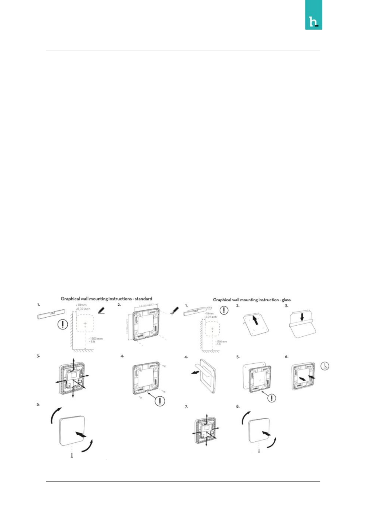
IMPORTANT! Read the safety instructions carefully before using the mounting instructions.
1. Unmount the back plate of the device, by carefully turning it counter clockwise. Use a spirit level
to adjust it horizontally. Height from floor to center of device approximately 1500 mm / 5 ft.
2. Use the holes in the back plate to mark out hole positions on the wall.
3. Decide on the direction you want to exit the cables and make sure the hole for the cable exit is
facing this direction.
Note! If you plan to route cables into the wall using the big open area in the middle of the back plate we
recommend facing the cable hole either up or down, not sideways.
4. Make sure that the markings are exactly leveled and drill the holes for the mounting bracket.
Mount the back plate to the wall with the screws and route the cables through the appropriate
cable channels on the device.
Note! Use 2 ¡ 4 screws depending on the structural capacity of the wall. Always drill holes and use
suitable plugs for wall types such as concrete, plaster etc. Choose a screw type that is suitable for the type
of plug and wall concerned. Use screws with a diameter of 4 ¡ 5 mm / gauge # 7 - 10 and minimum
length of 35 mm / 1- 3 /8¡. If uncertain always contact a specialist or dealer for assistance with wall
mounting.
Note! Do not remove the protective film on the back of the mounting bracket. The ¡sticky surface¡ should
only be used for glass wall mounting.
5. Mount the device on the bracket by fitting the talons on the back plate with the holes in the
device and gently turn it clockwise to snap it in place. Secure it with the safety screw.
Glass walls
IMPORTANT! Read the safety instructions carefully before using the mounting instructions. For
mounting on smooth glass surfaces only! Make sure the surfaces are clean, dry and above 15¢C / 59¢F
before mounting! Avoid mounting in direct sunlight!
7
Page 8
Humly Room Display - User Manual Prepared By: Haian & Robin
Revision - B Approved By:
1. Start by cleaning glass wall surface with alcohol and let the surface be completely dry.
Recommended room temperature during this operation min 15¢C / 59¢F. Apply a horizontal
adjusted tape on the glass wall as a guide for the adhesive foil. Height from floor to center of
device approximately 1500 mm / 5 ft.
2. Remove the protective film partly from the glass wall adhesive foil.
3. Press the foil on to the glass wall with a force of approximately 3 kgf. Use a rubber roller or
scraper for this operation. Make sure to remove any trapped air bubbles.
4. Remove protective film from the back plate.
5. Use guides on foil to make sure bracket is in line with glass wall sticker. Decide on the direction
you want to exit the cables and make sure the hole for the cable exit is facing this direction.
Note! The glue will bond immediately, and cannot be remounted.
6. Press mounting bracket into glass wall foil for 20 seconds by a force of approximately 6 kgf.
Leave bracket on glass wall for 20 min before final assembly.
7. Route the cables through the appropriate cable channels on the device.
8. Mount the device on the bracket by fitting the talons on the back plate with the holes in the
device and gently turn it clockwise to snap it in place. Secure it with the safety screw.
8
Page 9

Humly Room Display - User Manual Prepared By: Haian & Robin
Revision - B Approved By:
Technical Specifications
Visual interface
● 8 inch capacitive touch with anti-fingerprint treatment.
● 48 LED RGB light aura and indication light.
Connectivity
● Wifi 802.11 a/b/g/n*
● Ethernet RJ-45, 10/100/1000 Mbit, PoE & PoE+(IEEE 802.3af)
● NFC/RFID 13.56 Mhz (ISO/IEC 14443A/B), MIFARE 4K/1K
● Bluetooth 5.0
Power
● Power over Ethernet (PoE), or 12V AC/DC power adapter
Compatible Platforms
● Microsoft Office 365
● Microsoft Exchange 2019
● Microsoft Exchange 2016
● Microsoft Exchange 2013
● Microsoft Exchange 2010
● Google G Suite
● IBM/Lotus Domino Smartcloud
● IBM/Lotus Domino 8.5.3 ¡ 9.x
User Interface Languages
● Arabic - Catalan - Chinese (simplified) - Chinese (traditional) - Czech - Danish - Dutch - English Estonian - Finnish - French - Galician - German - Italian - Japanese - Latvian - Lithuanian Norwegian - Polish - Portuguese - Russian - Spanish - Swedish.
9
Page 10
Humly Room Display - User Manual Prepared By: Haian & Robin
Revision - B Approved By:
API & Other
● Open API for third party integration
● Communication via real-time two-way connection
● Remote management with multi-site support
● Real-time monitoring & statistics
Size and Weight
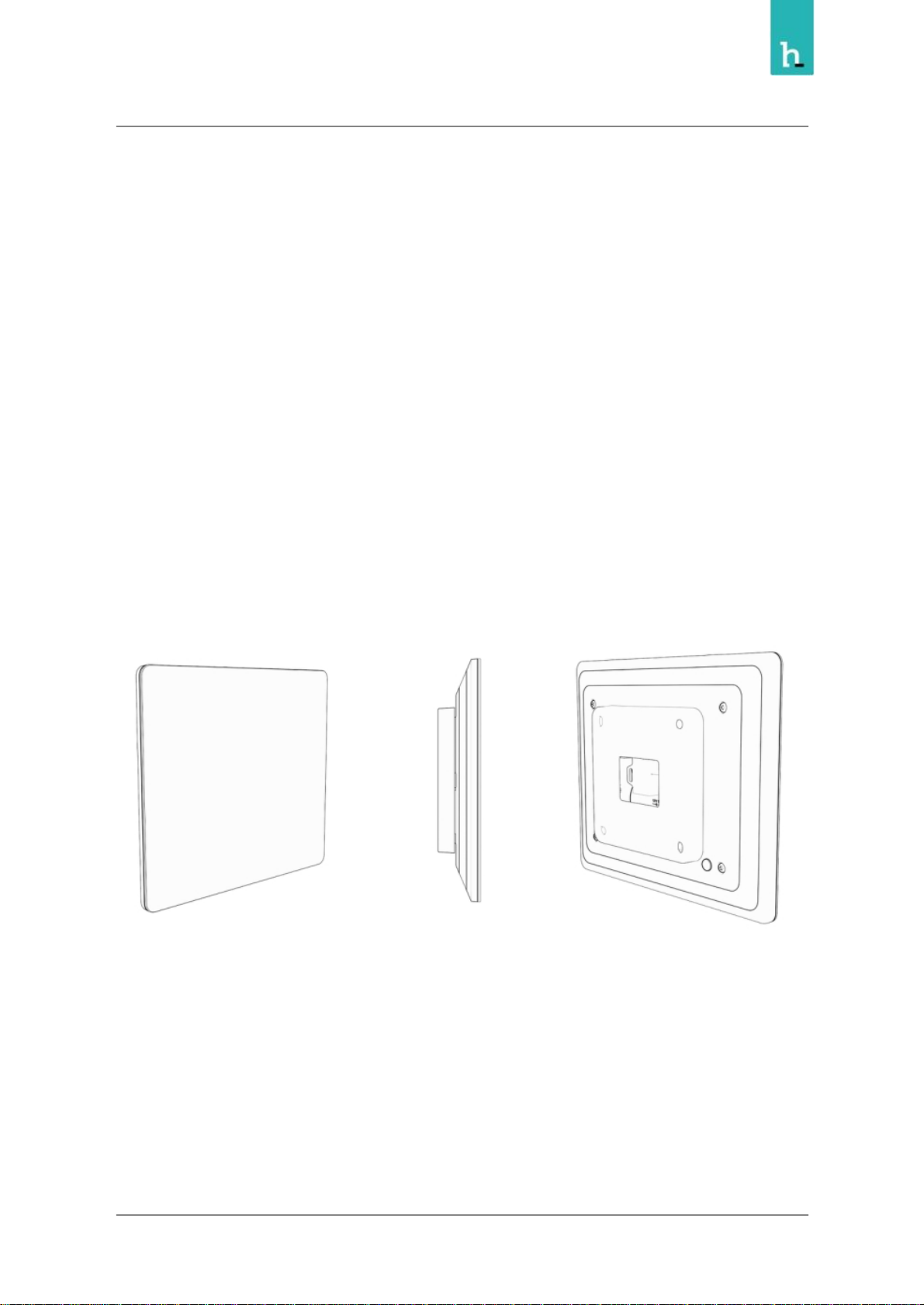
● Size (WxHxD):
○ With wall mount: 183 x 157 x 28.7 mm
○ Without wall mount: 183 x 157 x 25.6 mm
● Weight: 650 grams (22.9 ounces)
10
Page 11
Humly Room Display - User Manual Prepared By: Haian & Robin
Revision - B Approved By:
Architecture Overview
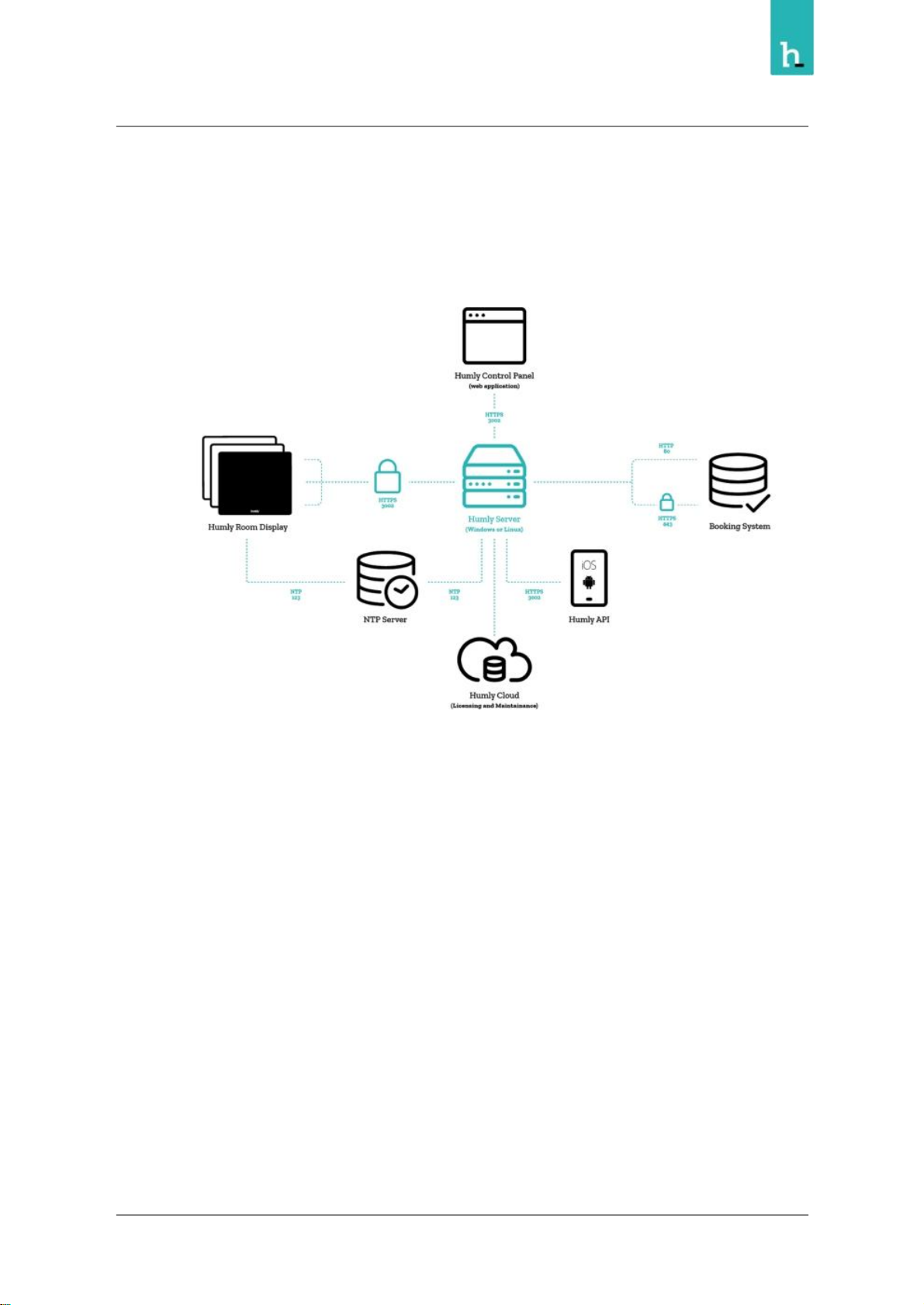
● The Humly Server communicates with Humly Room Displays via HTTPS over a configurable
port (default 3002).
● The Humly Control Panel web application communicates with the Humly Server using
configurable HTTP port during initial setup to configure SSL certificates. After SSL has been
configured all communication uses HTTPS on the port configured during initial setup (default
port 3002).
● The Humly Home server communicates with the booking system via either HTTP (80) or HTTPS
(443)
● The system uses configurable NTP servers using UDP over port 123 to synchronize time and
date.
● The system will connect to Humly Cloud using HTTPS over port 443 to validate and renew
licenses and provide maintenance services like updates and error logging.
● Other devices and integrations can be allowed to communicate with the Humly Server over
HTTPS using the same port that has been configured for the Humly (default 3002).
11
Page 12
Humly Room Display - User Manual Prepared By: Haian & Robin
Revision - B Approved By:
Getting Started
Initial Boot & Network Configuration
HRD can be mounted to both standard walls and glass walls. Mounting kits for both are included in the
box and the cable can be routed to any of the four sides or into the wall. The wall mount has a bayonet
mount to snap on the unit, which also can be secured with a screw.
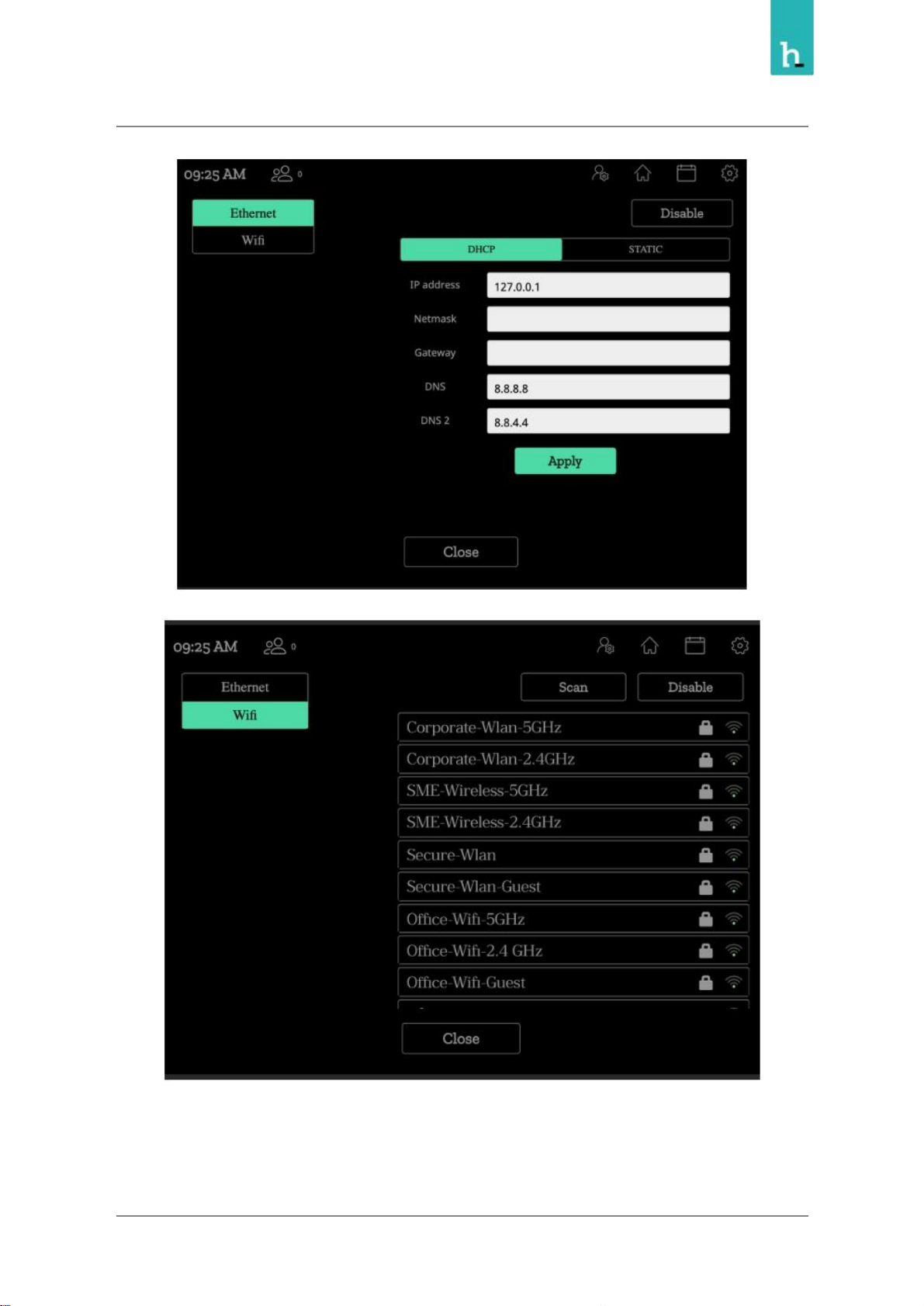
HRD can be connected via either a wired Ethernet connection or Wifi using a dynamic or static IP.
Once the device boots up, the logo should appear during the initial OS boot, then the configuration
options will follow
Based on your network setup, you can select between Ethernet or Wifi configuration
12
Page 13
Humly Room Display - User Manual Prepared By: Haian & Robin
Revision - B Approved By:
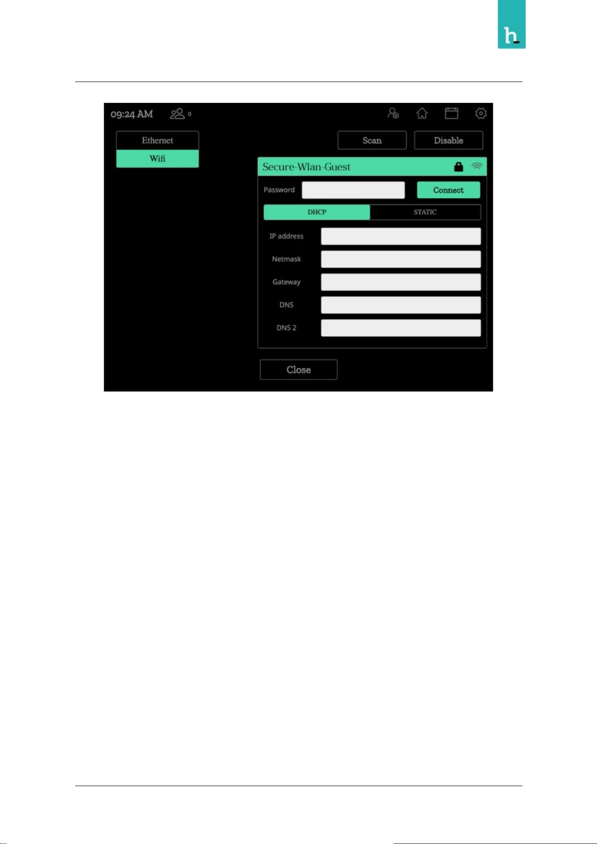
Connect to your prefered Wifi network and setup the IP configuration
13
Page 14
Humly Room Display - User Manual Prepared By: Haian & Robin
Revision - B Approved By:
Installation
Now the HRD can be connected to Humly Control Panel, which is connected to the booking system.
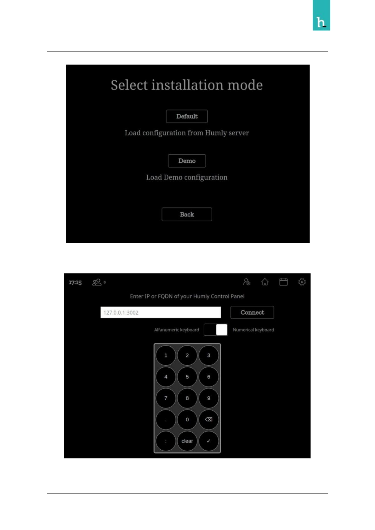
You need to enter the FQDN or the IP Address of the Humly Control Panel server and select the room you
want to assign the device ro.
Select Default Mode
14
Page 15
Humly Room Display - User Manual Prepared By: Haian & Robin
Revision - B Approved By:
Enter the IP address of the Humly Control Panel
Or enter the FQDN for Humly Control Panel
15
Page 16
Humly Room Display - User Manual Prepared By: Haian & Robin
Revision - B Approved By:
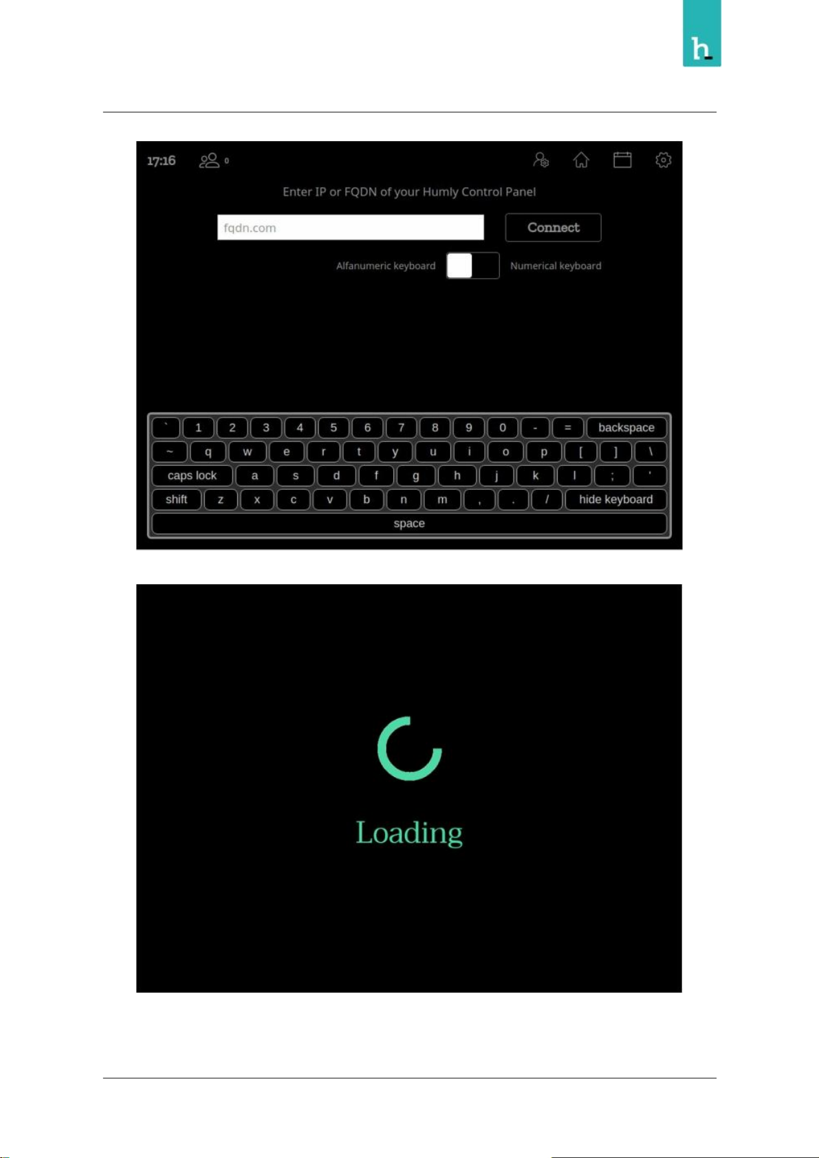
Wait for the HRD to connect and load
16
Page 17
Humly Room Display - User Manual Prepared By: Haian & Robin
Revision - B Approved By:
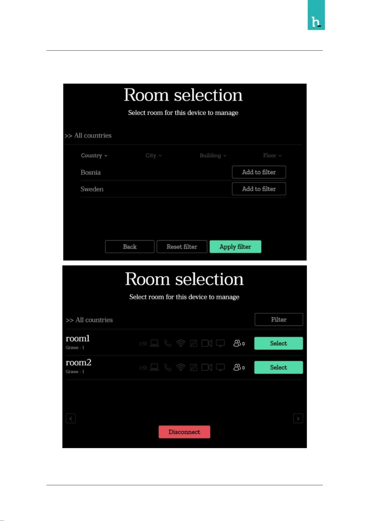
Select the room you want to connect your HRD to, you can apply filters to based on the country, city or
building.
Now the Humly Room Display unit should be ready to use!
17
Page 18
Humly Room Display - User Manual Prepared By: Haian & Robin
Revision - B Approved By:
Humly Room Display - User Guide
Status LED Colors
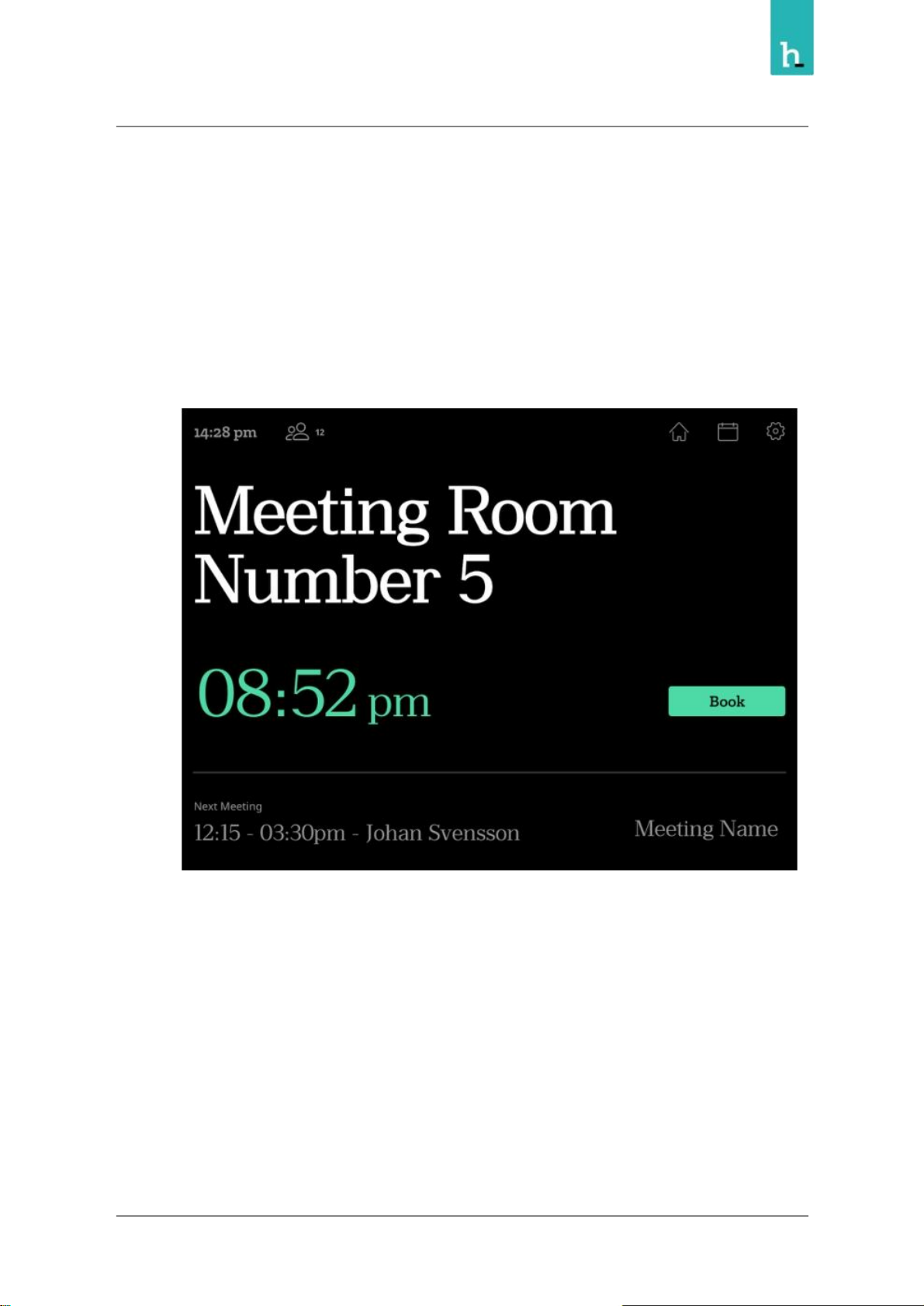
The Humly Room Display has three status led colors which user can use to recognize the room
availability
● Green: The room is free for more than 10 minutes.
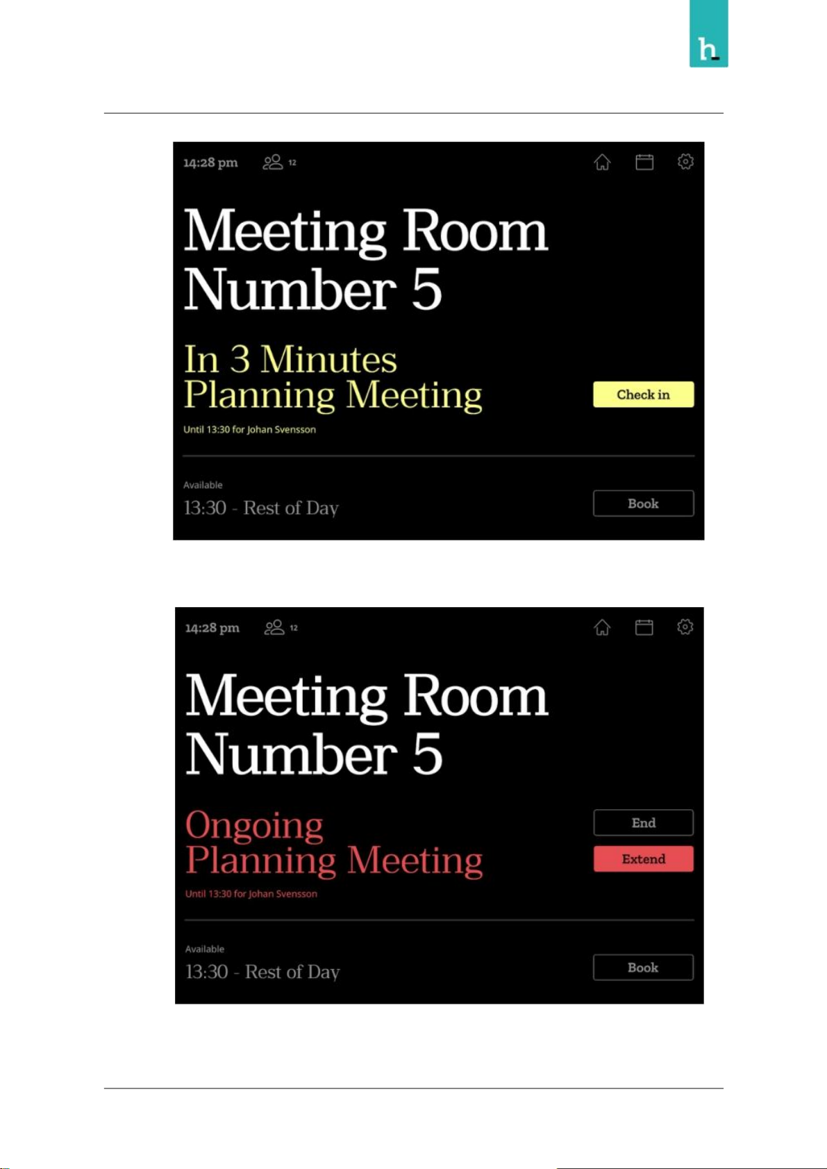
● Yellow: A meeting is about to start soon, in less than 10 minutes, and or, the room needs to be
checked in.
18
Page 19
Humly Room Display - User Manual Prepared By: Haian & Robin
Revision - B Approved By:
● Red: The room is busy.
19
Page 20
Humly Room Display - User Manual Prepared By: Haian & Robin
Revision - B Approved By:
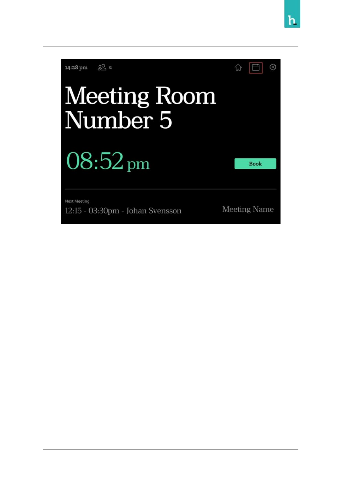
Main screen
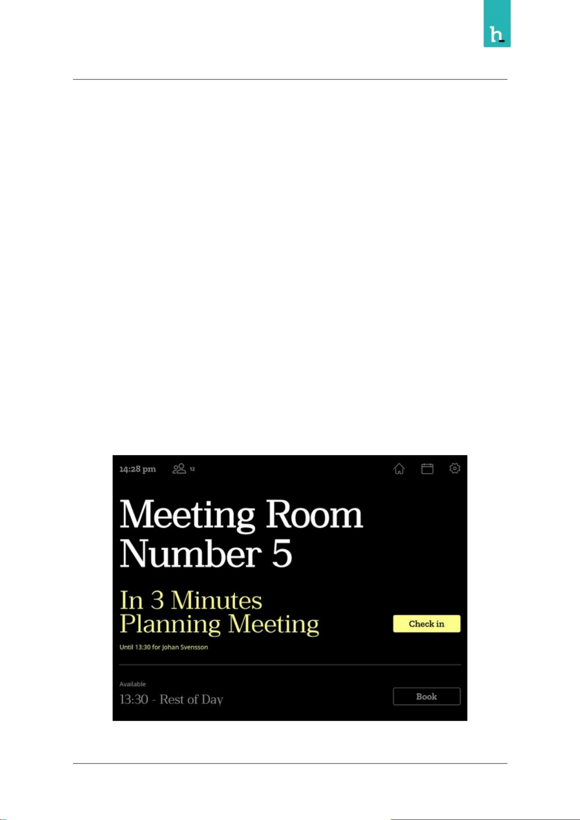
From the main screen you can see details about the meeting room, and you can perform the following
actions:
● Book instant meeting
● Book future meeting
● Extend ongoing meeting
● End ongoing meeting
Some of the above functions can be disabled or secured based on user PIN or RFID for each room from
the Humly Control Panel.
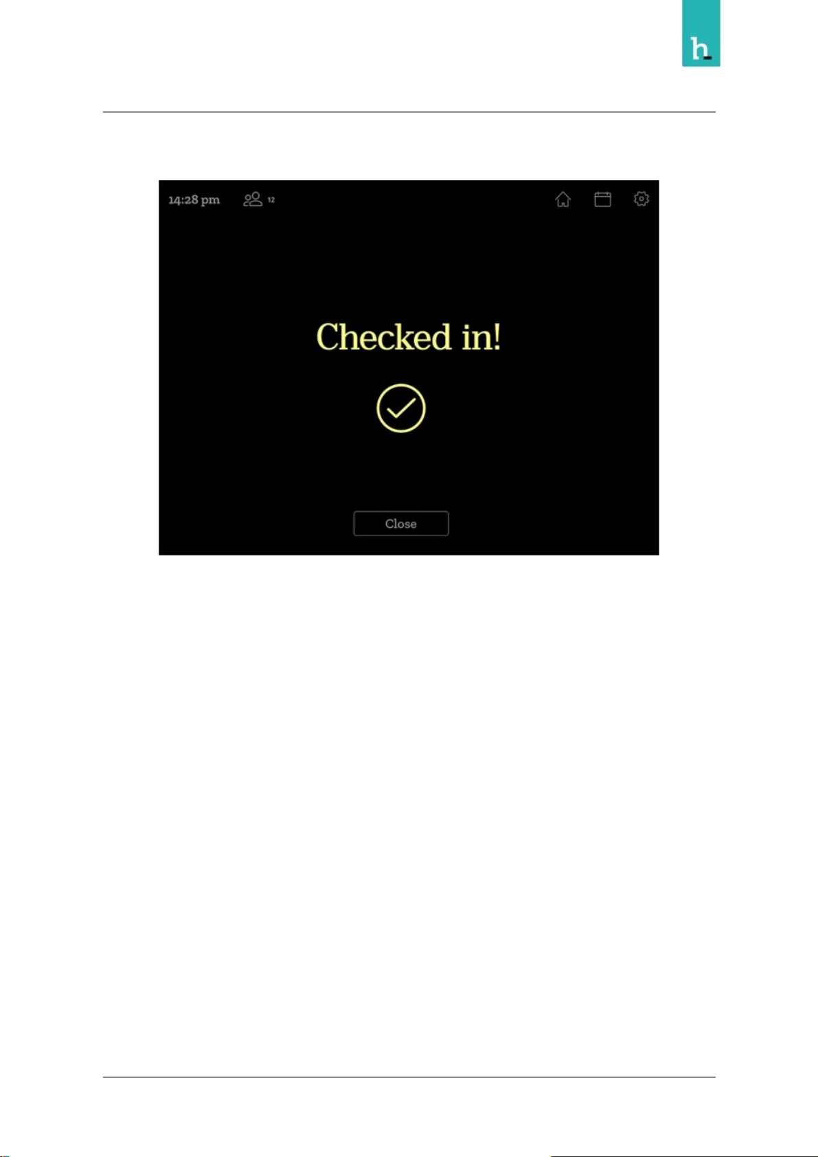
Check-in
The check in function is a way to enhance meeting room utilization by freeing up the rooms where no
one shows up for the booking.
This function can be enabled and customized from the Humly Control Panel, if enabled, a check-in button
will appear 10 minutes before the meetings start and remain until 5-30 minutes after the meetings start
depending on the settings in Humly Control Panel.
20
Page 21
Humly Room Display - User Manual Prepared By: Haian & Robin
Revision - B Approved By:
If a user checked in the meeting, a confirmation message will appear on the device.
If no check-in is made on the screen during the check-in time frame, the meeting will be ended short to
free up the meeting room for others to use.
Calendar screen
The calendar screen can be accessed from the main screen by pressing the calendar icon.
21
Page 22
Humly Room Display - User Manual Prepared By: Haian & Robin
Revision - B Approved By:
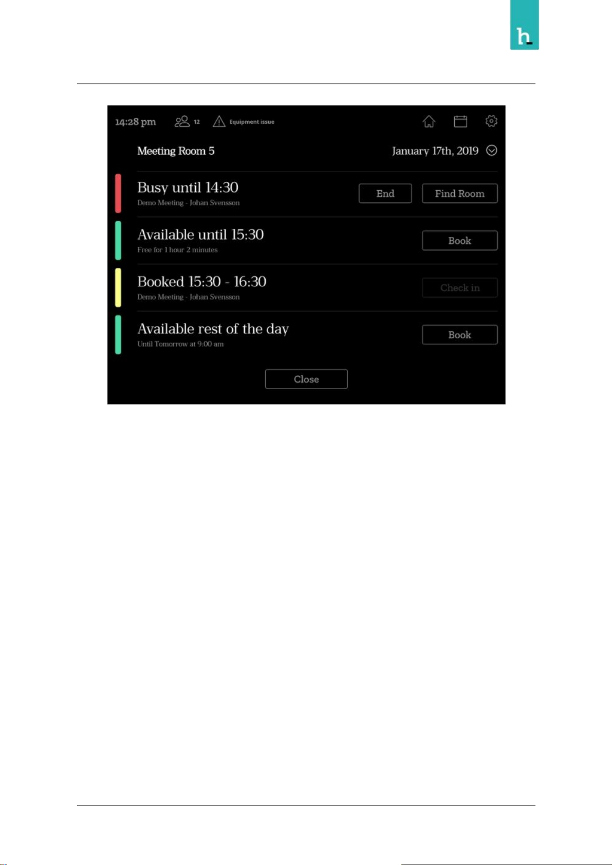
From the calendar view, you can see the room schedule, you can also book meeting by pressing Book
button on available slot, you can extend a meeting or delete scheduled meeting.
The schedule view and the available actions may vary based on the room settings in Humly Control
Panel.
22
Page 23
Humly Room Display - User Manual Prepared By: Haian & Robin
Revision - B Approved By:
23
Page 24
Humly Room Display - User Manual Prepared By: Haian & Robin
Revision - B Approved By:
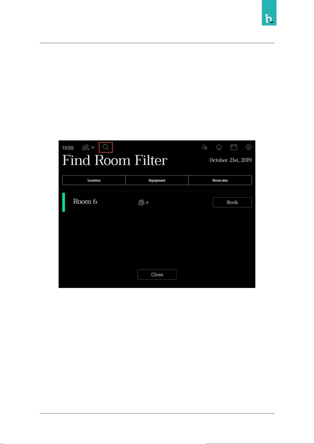
Room Finder
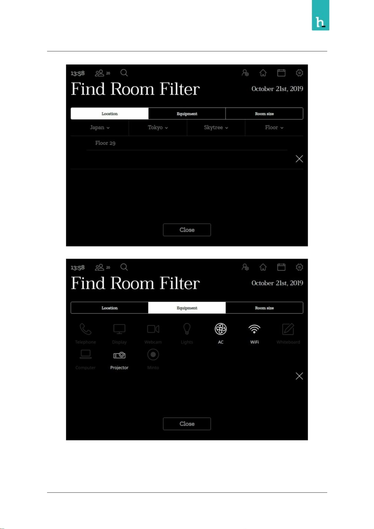
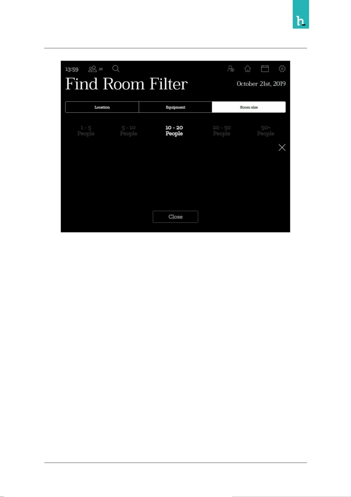
The room finder is a tool to find an available room based on specific filters, like room availability, location,
size and equipment.
You can use this function to book instant meeting and future meetings for another room which match
the applied filters.
Room finder can be accessed by pressing the search icon in the top left corner from the main view.
Then you can apply your search filters based on the locations, equipments and room size.
24
Page 25
Humly Room Display - User Manual Prepared By: Haian & Robin
Revision - B Approved By:
25
Page 26
Humly Room Display - User Manual Prepared By: Haian & Robin
Revision - B Approved By:
Report room equipment
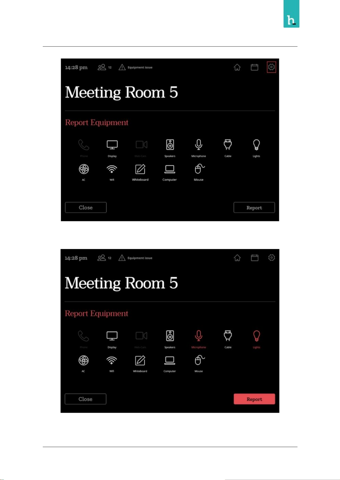
Reporting room equipment from Humly Room Display is a feature for notifying the responsible person
about a broken or malfunctioning equipment in the meeting room by sending automatic email, and
signaling other users about the issues in this meeting room.
You can access the report equipment screen by pressing the icon in the top right corner.
26
Page 27
Humly Room Display - User Manual Prepared By: Haian & Robin
Revision - B Approved By:
To submit a report, highlight the equipment icons and then press "Report"
27
Page 28
Humly Room Display - User Manual Prepared By: Haian & Robin
Revision - B Approved By:
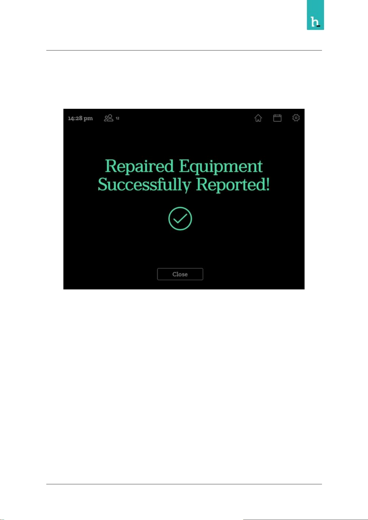
A confirmation message will appear after successful report, and triangle notification in upper left corner
of the HRD.
You can at anytime report the same equipment as Repaired the same way of reporting broken
28
Page 29
Humly Room Display - User Manual Prepared By: Haian & Robin
Revision - B Approved By:
Administration menu
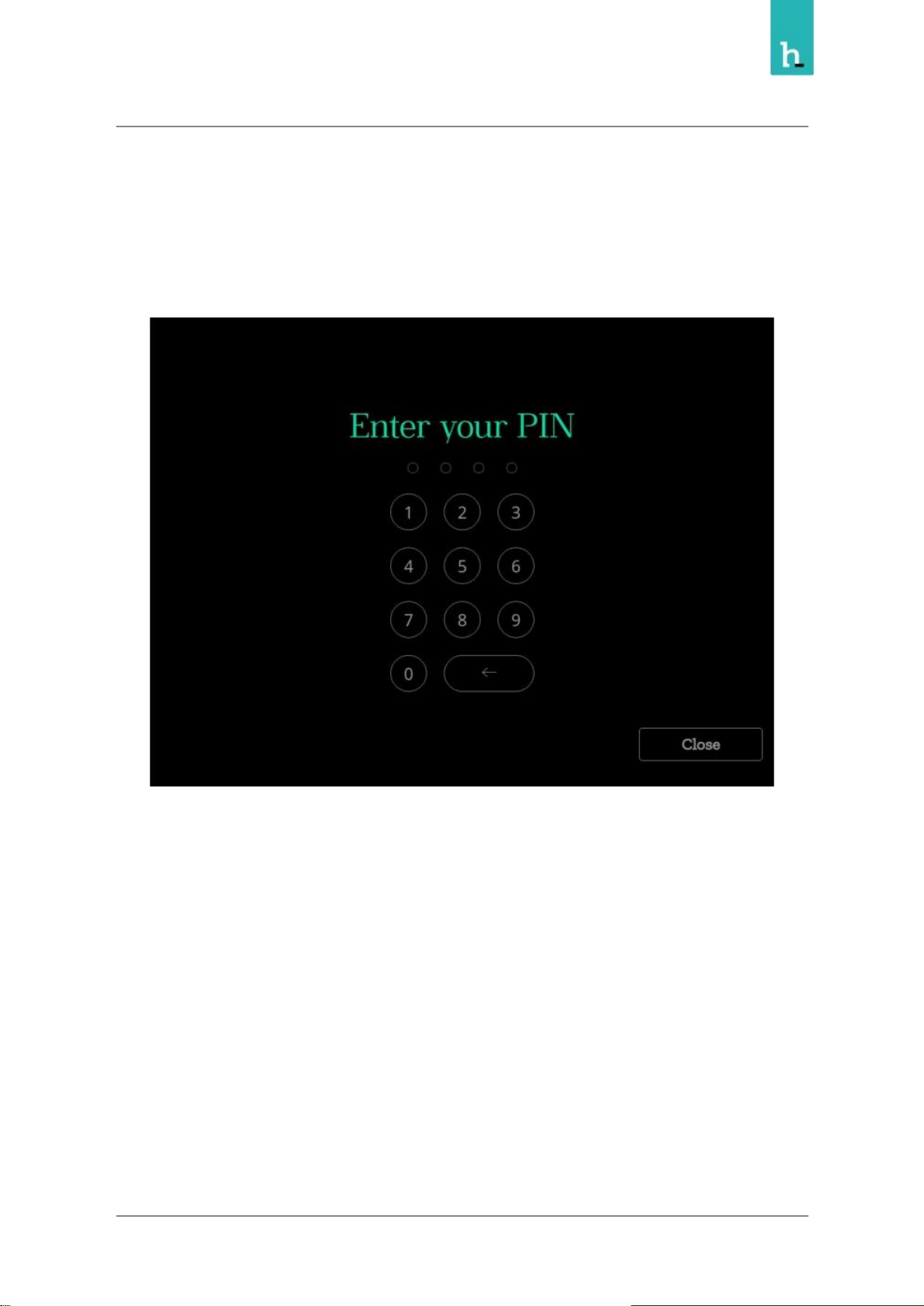
To access the administrator panel, press the icon in the top right part from the main screen or any screen
This will prompt you to authenticate as an administrator using PIN or RFID
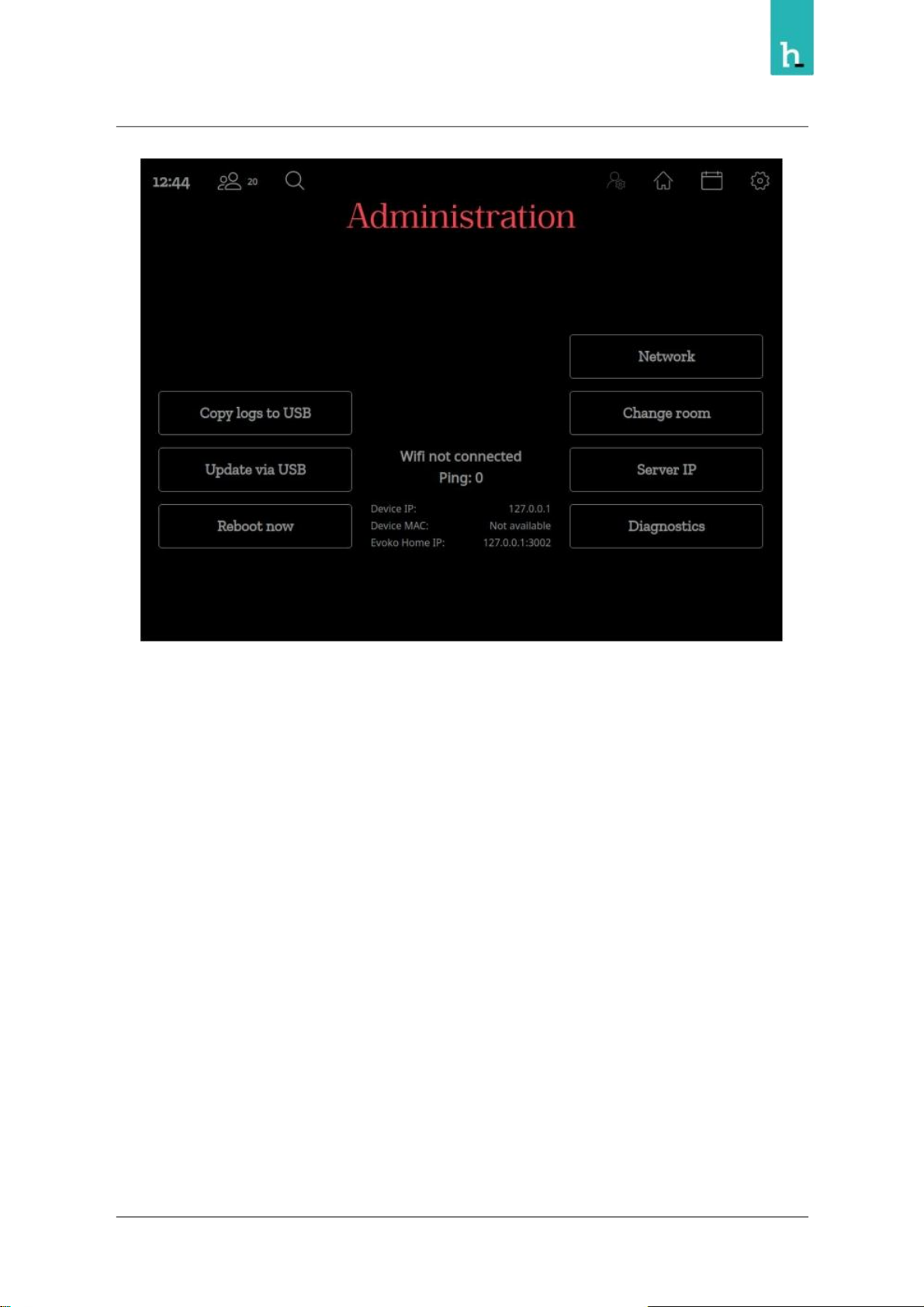
Once authenticated, the administrator panel will be shown, from the panel you can perform the below
actions
29
Page 30
Humly Room Display - User Manual Prepared By: Haian & Robin
Revision - B Approved By:
Copy logs to USB
For troubleshooting and support, you might need to copy the device logs, in this case, insert USB
formatted as FAT 32 and press Copy logs to USB button.
Update via USB
To update the HRD device firmware, you can copy the firmware upgrade file into USB stick, plug it into
the device and press upgrade.
For more details about firmware reset & upgrade. Refer to Firmware Upgrade section in the support
portal
Reboot Now
Reboots the HRD
30
Page 31
31
Humly Room Display - User Manual Prepared By: Haian & Robin
Revision - B Approved By:
Network
Opens the network configuration menu where the two network interfaces Ethernet and Wifi) can be
configured.
Change Room
You can point the HRD to use another room configured on the same Humly Control Panel server.
Server IP
The HRD can be disconnected from a Humly Control Panel Server and connect into another server.
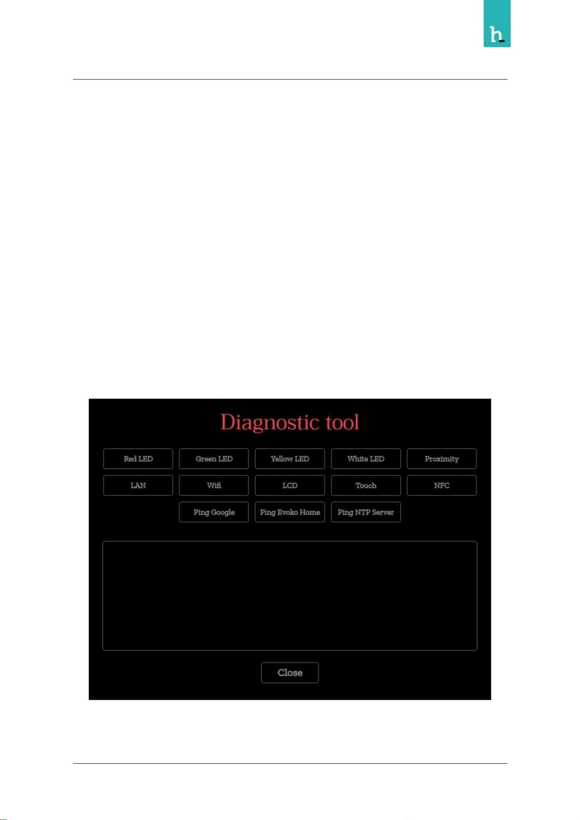
Diagnostic
Opens a diagnostics menu which allows for test of the LEDs, the touch panel, network connection and
some other basic functional tests.
Page 32

This equipment has been tested and found to comply with the limits for a Class B digital device, pursuant to part
installed and used in accordance with the instructions, may cause harmful interference to radio communications.
(2) this device must accept any interference received, including interference that may cause undesired operation.
used for this transmitter must be installed to provide a separation distance of at least 20 cm from all persons and
Regulatory and Certification
FCC
FCC ID: 2APYB- HUM1001
FEDERAL COMMUNICATIONS COMMISSION INTERFERENCE STATEMENT
15 of the FCC Rules. These limits are designed to provide reasonable protection against harmful interference in
a residential installation. This equipment generates, uses and can radiate radio frequency energy and, if not
However, there is no guarantee that interference will not occur in a particular installation. If this equipment does
cause harmful interference to radio or television reception, which can be determined by turning the equipment
off and on, the user is encouraged to try to correct the interference by one or more of the following measures:
-Reorient or relocate the receiving antenna.
-Increase the separation between the equipment and receiver.
-Connect the equipment into an outlet on a circuit different from that to which the receiver is connected.
-Consult the dealer or an experienced radio/ TV technician for help.
CAUTION:
Any changes or modifications not expressly approved by the grantee of this device could void the user's
authority to operate the equipment.
This device complies with Part 15 of the FCC Rules. Operation is subject to the following two conditions:
(1) this device may not cause harmful interference, and
RF exposure warning
This equipment must be installed and operated in accordance with provided instructions and the antenna(s)
must not be co-located or operating in conjunction with any other antenna or transmitter. End-users and
installers must be provide with antenna installation instructions and transmitter operating conditions for
satisfying RF exposure compliance.
 Loading...