

Page 1
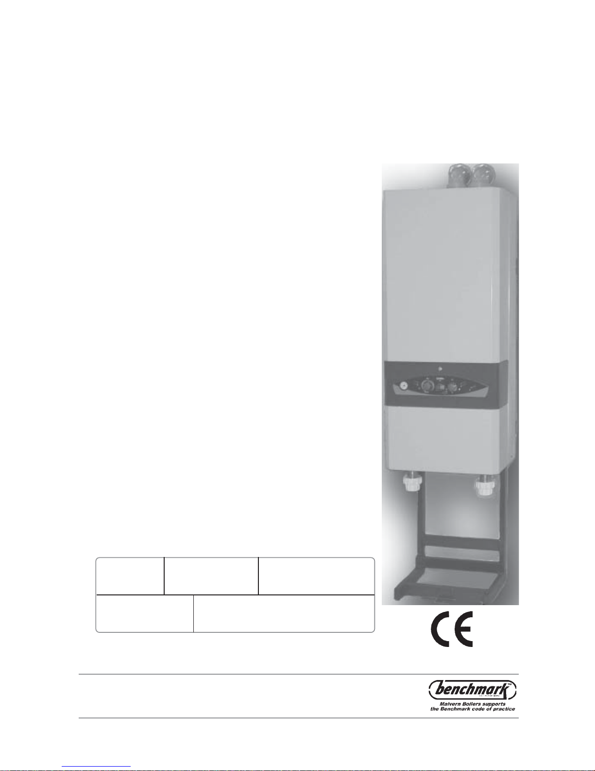
GC No. 47 555 02 and 47 555 17
WRc No. 95 110 46
0087
Certikin
100 & 100W Condensing
Pool Heaters
Note to the Installer: Natural gas Only
Please leave these Instructions adjacent to the meter.
Installation,
Service & User
Instructions
Model: MBC100N MBC100NW
Serial No:
Page 2

1
1. USER
INSTRUCTIONS
1.1 Important Safety Notes
1.2 Connections
1.3 Quick Start
1.4 Summary of Controls
1.5 Re-Pressurising
1.6 Running the Pool Pump
1.7 Switching the Heater Off
– temporarily
1.8 Switching off for the
Winter
1.9 Maintenance
1.10 T roub le Shooting –
Failure to Start
1.11 Service
1.12 Water Quality
2. INSTALLATION
2.1 Introduction
2.2 Standards & Regulations
2.3 If Combined with a
Heating System
2.3 Standards & Regulations
2.4 Heater Controls
2.5 Gas Supply
3. FLUEING
3.1 Air Supply
3.2 Water Supply
3.3 Condensate Drain
3.4 Sealed Systems
3.5 Electricity Supply
4. INSTALLATION
WIRING
4.1 Wiring
4.2 Installation of Heater
4.3 Fixing the Heater
4.4 Terminal
4.5 Twin Pipe Assembly
4.6 Plumbing
4.7 Gas Connection
4.8 Condensate Connection
5. SPACE HEATING
5.1 System Design
5.2 Electrical Connections
6. COMMISSIONING
6.1 General Information
6.2 Procedure
6.3 Setting up the Controls
6.4 Pump Pressure Switch
6.5 Responsibility
7. FAULT FINDING
7.1 Heater Control
7.11 Control F ault Diagnostics
7.2 Ignition Faults
8. SERVICING
8.1 Heater Servicing
8.2 Changing Components
8.2.1 Control Boards
8.2.2 Gas Valv e
8.2.3 Sequence Controller
8.2.4 CVI V alve and
Full Pressure Set Up
8.2.5 Pressure Gauge
8.2.6 Pump
8.2.7 Diverter V alve
8.2.8 Safety V alve
8.2.9 Water to Water Heat
Exchanger
8.2.10 Flow Regulator and
Strainer
8.2.11 DHW T emperature Sensor
8.2.12 Removing the Case
8.2.13 Fan Assembly
8.2.14 Air Pressure Switch
8.2.15 Flue Thermostat
8.2.16 Pump Overrun
Thermostat
8.2.17 Control Sensor
8.2.18 Overheat Cut-Off Device
8.2.19 Electrode and HT Lead
8.2.20 Pilot Assembly
8.2.21 Burner
8.2.22 Main Injector
8.2.23 Combustion Chamber
Insulation
8.2.24 Primary Heat Exchanger
8.2.25 Secondary Heat
Exchanger
9. PARTS
9.1 Spares
9.2 Electrical Components
1:4 Control Panel
1:5 The Filling Loop
2:3 Typical Circuits
3:4 Alternative Methods of
Filling a Sealed System
4:1 Installation Wiring
Diagram for Heater
Controller
4:3 Fixing Positions
4:5 T win Flue P ositions
4:8 Installation Dimensions
Service Access
5:2a Model 100 Schematic
Wiring
5:2b Model 100W Schematic
Wiring
5:1 Hydraulic Schematic
6:2 a Model 100 Gas V alve
6:2 b 100W Gas V alve
6:3 Control Display in Setup
Mode
6:4:a Adjustment Knob
6:4:b Heater Installation Limits
7:1 Control Display
7:2:a Indicator Lights, Model
100 Only
7:2:b Fault Finding Operation
Sequence, 100W
7:2:c Fault Finding Hot Water
Operation, 100W
7:2:d Fault Finding P ool or
Space Heating, 100W
8:2:2 Gas V alve Model
8:2:4 CVI V alve Modureg
Operator
9:2 Electrical Components
10:1 Major Components
10:2 Example Condensate
Disposal Methods
10:3 Condensate Drain Tap
CONTENTS
FIGURES
100 Gas Condensing Pool Heater
21/10/03
Page 3

1: USER INSTRUCTIONS
1:1 Important Safety Notes
T o obtain the best possib le performance and trouble
free operation from your Heater , it is important that
you read these instructions carefully . Your Pool
Heater has built-in safety features, which are
detailed in the relevant section of this manual.
If it is known or suspected that a fault exists on the
Heater, it MUST NO T be used until the f ault has
been corrected by a competent engineer (see
Section 1:10, Trouble Shooting - Failure to Start)
It is essential that these instructions are strictly
followed f or saf e and economic operation. F ailure to
observe these instructions may invalidate your right
to free breakdown cover during the guarantee
period.
We recommend that you keep these instructions in
a place near your Heater for easy reference.
1:2 Connections
Your Heater should be connected to an electrical
supply complying with the Electrical Wiring Regulations (BS7671): as well as a gas supply complying
with BS6891; and an appropriate flue system.
AL WAYS SWITCH OFF THE ELECTRICAL
SUPPLY before removing any of the covers for
cleaning.
If any part of the Heater or its flue is modified then
the guarantee will be invalidated.
1:3 Quick Start
Check the Electricity and Gas supplies to the
Heater are on. If the Pool Pump is not controlled by
the Heater, turn it on. Turn on the Heater by turning
the Pool Temperature Control Knob clockwise to
show the required Pool temper ature, the Heater will
fire.
If the Heater fails to light see Section 1:10, T roub le
Shooting - Failure to Start)
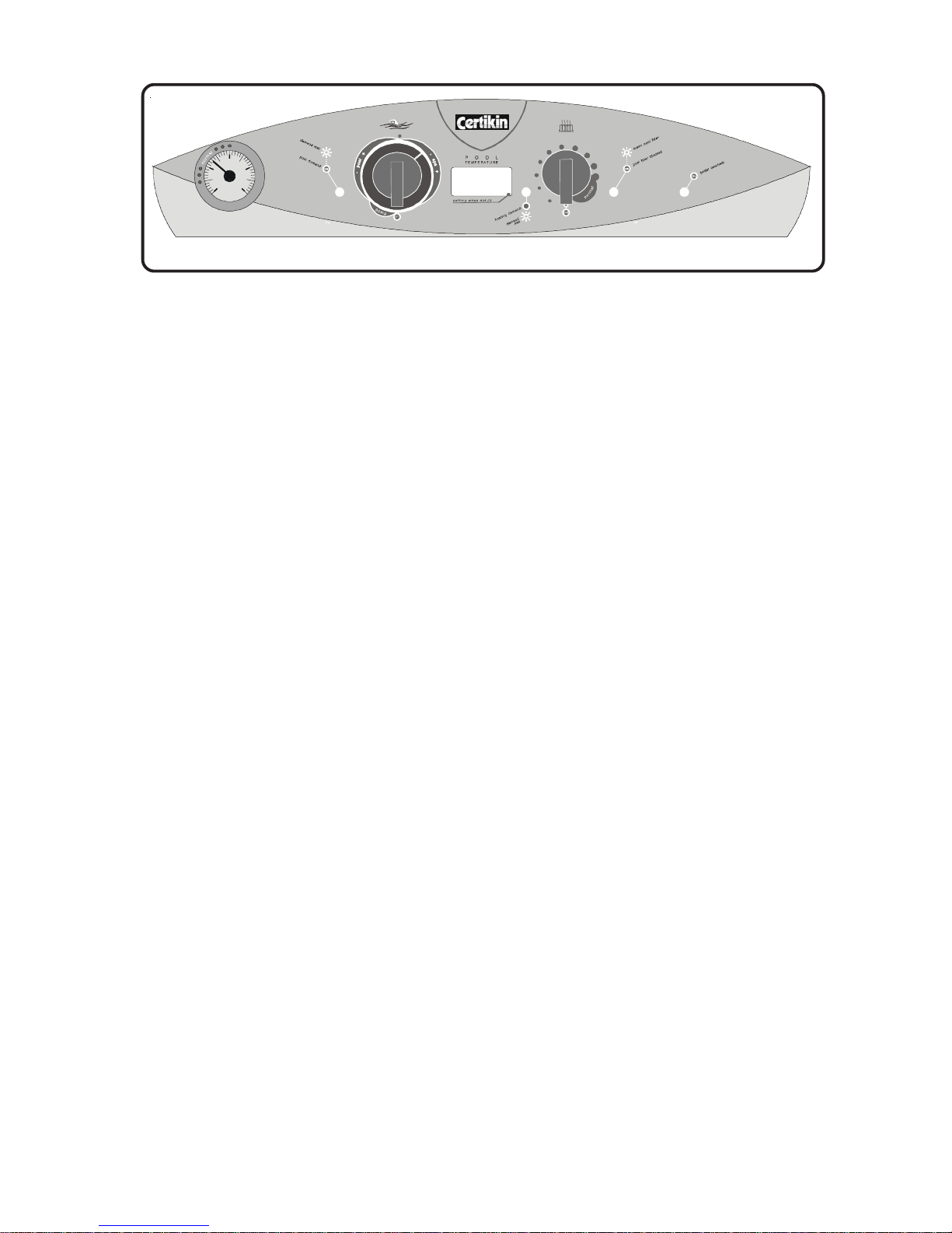
1:4 Summary of Controls (left to right)
Heater Pressure Gauge
Normal - The needle should be in the area indicated
as * * NORMAL * * , if low , re-pressurise, see
Section 1:5
Flashing - The P ool Heating Demand is Met , the
pool is up to temperature.
Temperature is displayed after 3 seconds.
- Spa + - Setting for Spa Temperatures. Required
temperature is displayed when setting, actual Spa
T emper ature displayed after 3 seconds.
(NOTE: The Heater is delivered set to display in Fahrenheit. For a Centigrade display,
see 6:3
Commissioning Section of Installation Instructions)
Pool Temperature Mechanical Stop
Stop – This can be used to obtain a repeatab le
setting and to limit maximum pool temperature. To
set, loosen the screw , adjust as required and then
re-tighten.
Pool T emperature Display
Display - Normally shows the actual P ool Tempera-
ture, but also displa ys the Setting Temperature and
a Setting Dot lit whilst being adjusted. The display is
also used for commissioning and diagnostic purposes.
Heating Demand LED - GREEN
(Only in use when heating system connected)
Off - There is no Heating Demand , heating is
switched off.
On - There is a Heating Demand , heating is on b ut
not yet up to temperature.
Flashing - The Heating Demand is met , heating is
up to temperature.
Heating Temperature Control Knob
(Only used when heating system connected)
Off - There is no Heating Demand, heating is
switched off.
Normal - Normal setting for heating, it can be
adjusted lower if required.
(NOTE: Supplied set for Pool Priority. It will satisfy the
Pool Temperature before supplying full Heating. To
change the priority,
see 6:3
Commissioning Section of
the Installation Instructions)
Filter LED - YELLO W
On - Pool Filter Bloc k ed - Insufficient pressure,
possibly due to a blocked pool filter. The heater will
not run.
Flashing - Clean Pool Filter - The filter ma y require
back washing. The heater will run. Can be reset by
turning the Pool Temperature knob off and back on
again.
Pool Temperature Control Knob
16°C to 41°C (60°F to 106°F)
Off - There is no P ool Heating Demand , pool
heating is off.
Pump - Runs Pool Pump only, if connected via
heater. ‘P’ is indicated on P ool T emperature Displa y .
- Pool + - Setting f or pool temperatures. Requested
temperature is displayed when setting, actual Pool
2
100 Gas Condensing Pool Heater01/06/02
Page 4
Heater Overheat LED - ORANGE
On - Heater Ov erheat - This indicates that the
Heater has overheated and shut down. See Overheat Reset instructions below.
Overheat Reset 100 Only
In the unlikely event of an Overheat it will necessary to obtain the assistance of a competent person
to reset the thermostat.
Turn the Mains supply off. Remov e the single fixing
screw holding the Electrical Chassis and pull it out,
hanging it on the back support. Remov e the Controls Cover and locate the Reset Switch on the side
of the Control Chassis. Turn it off then back on
again.
Replace all the panels in reverse order .
If the Heater repeated overheats a Service Engineer
should be called to inspect the Heater.
Overheat Reset - 100W Model Only
In the unlikely event of an Overheat it will necessary to obtain the assistance of a competent person
to reset the thermostat.
The procedure is detailed in Section 8:2:18
If the Heater repeated overheats a Service Engineer
should be called to inspect the Heater.
Automatic Frost Protection
The Heater will automatically run a Frost Protection
routine if the temperature falls below 3°C (37°F). The
Pool Temperature Display will show 0°C. This will
include the use of the Pool Pump if it is connected
to the Heater.
1:5 Re-Pressurising
Connect a Mains W ater supply then connect the
free end of the braided flexible hose (the Filling
Loop) (see Fig.1.5) to the incoming mains connec-
tor.
Open the Valve to the supply , then, slo wly open the
V alve on the Base P anel until the Pressure Gauge
shows 1 Bar .
Close both valves then disconnect the Filling Loop.
ON
bar
0 4
2
1 3
u
s
e
r
i
n
s
t
r
u
c
t
i
o
n
s
i
n
s
i
d
e
u
s
e
r
i
n
s
t
r
u
c
t
i
o
n
s
i
n
s
i
d
e
100
s
e
e
i
n
s
t
r
u
c
t
i
o
n
s
1:6 Running the Pool Pump
If this option has been installed the Heater can run
the Pool Pump on its o wn. Turn the Pool Temperature Control Knob to ‘Pump’, just ne xt to Off .
1:7 Switching the Heater Off -
temporarily
The Heater may be stopped by turning the Pool
T emperature Control Knob and/or the Heating
T emperature Control Knob to OFF on Control P anel.
1:8 Switching off for the Winter
T urn both T emper ature Control Knobs to Off.
If the built in Frost Protection is required do not
isolate the Heater from its electrical supply .
If the Heater is to be shut off for the Winter, it is
advisable to have it thoroughly serviced when first
shut down. Thorough cleaning will minimise corrosion during the idle period.
1:9 Maintenance
For normal cleaning of the outside casing, simply
wipe with a dry cloth. To remove stubborn marks
and stains, wipe with a damp cloth and finish off
with a dry cloth. DO NO T use abrasive cleaning
materials. A spr a y of WD40 or similar will also help
to protect it.
The Heater must be serviced every year by a
qualified service engineer.
1:10 Trouble Shooting - Failure to Start
If the Heater fails to start, adopt the following
procedure:-
1. Check that the P ool pump is operating and that
the Filter lamp is not illuminated.
2. Check that the Heater Control Thermostat is set
high enough to be “ON” and that the Pool Demand lamp is on.
Fig 1:4
3
100 Gas Condensing Pool Heater 20/10/03
Page 5
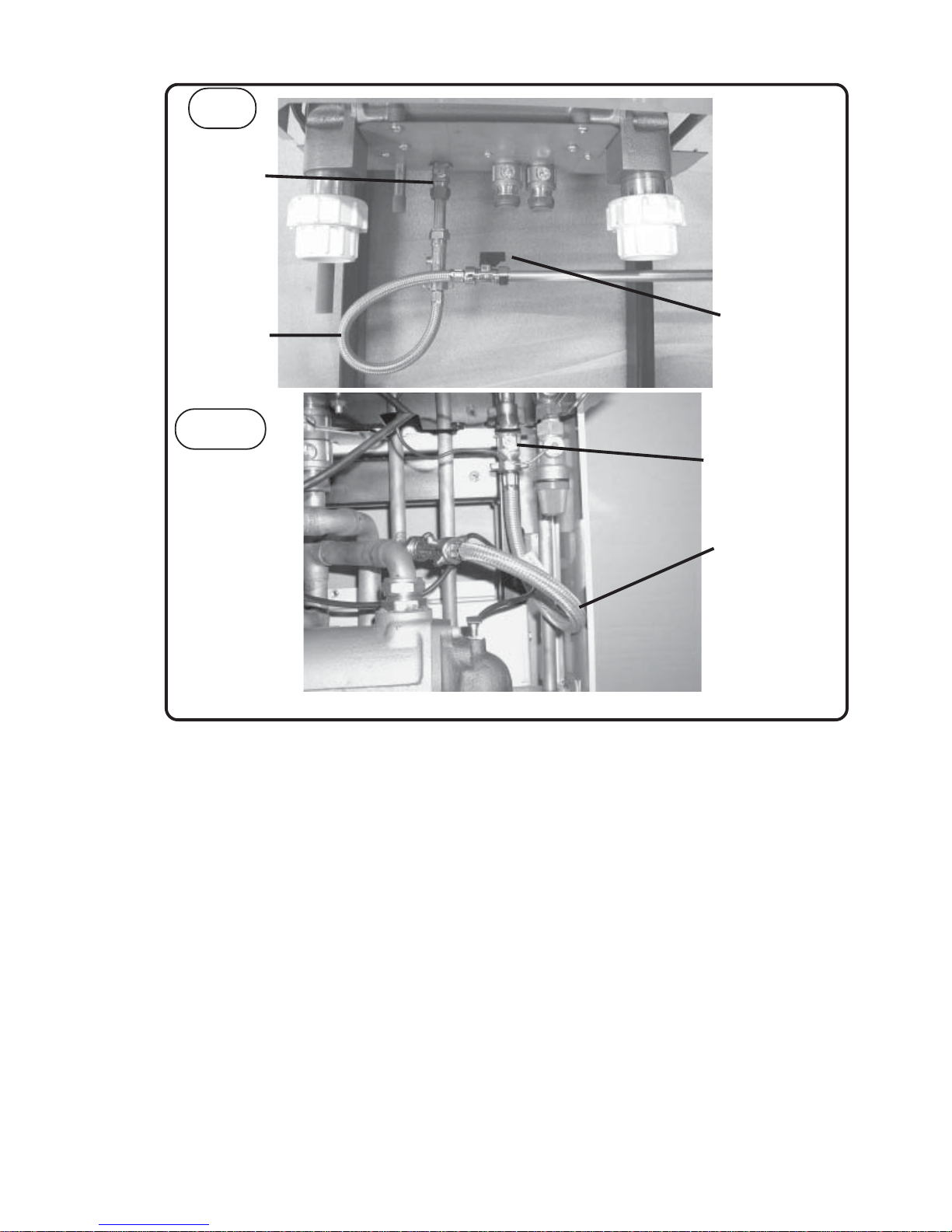
Fig 1:5
3. Check whether the Heater Overheat light on the
control fascia is glowing, if so it indicates an
overheat situation. (See Section 1:4) If the
Heater repeatedly overheats a Service Engineer
should be called to inspect the Heater.
1:11 Service
T o ensure efficient and reliable oper ation of the Heater
it is essential that the Heater is serviced every year.
The Manufacturer recommends this is prior to starting the Heater each season.
1:12 Water Quality
Chemical imbalance can cause severe damage to
your Heater and associated equipment.
Maintain the pool water pH between 7.4 and 7.6 and
ensure that the free chlorine levels are within the
range recommended by the chemicals manufacturer
for your size of pool.
Check the Filter regularly and keep the pool free of
debris such as leaves and grass cuttings.
4
100 Gas Condensing Pool Heater20/10/03
Filling Loop
First Valv e
Second V alve
100
Filling Loop
Second V alve
100W
Page 6

2 INSTALLATION
2:1 Introduction
This Manual covers Operation, Installation, Commissioning and Maintenance of the 100 and 100plus
Condensing Pool Heater .
The Pool Heater is :-
• Designed for heating pools and Spas by utilising
an internal water to water heat exchanger .
• Incorporates its own sealed system
components; pressure vessel, filling loop, safety
valve, and pressure gauge.
• Can also be used for space heating.
• The 100 Plus also provides Instantaneous Hot
W ater.
• Supplied with a manual reset limit thermostat.
• Suitable for new installations and for replacing
existing Heaters.
• Includes an internal automatic bypass to
accomodate all likely Space Heating designs.
These Instructions are for a Gas Fired, Condensing
Pool Heater which are room sealed and f an assisted
on the flue side. The flue system available is Twin
Pipe, horizontal total combined length of 22 metres
or vertical, up to a total length of 30 metres. The
ignition system is fully automatic. The 100 plus
incorporates electronic gas modulation.
The Heater casing is of polyester powder coated
enamelled zinc coated steel.
Includes all the components required for a sealed
system including a pump and is designed for the
connection of an optional Heating or Hot W ater
system.
It includes a pump overrun device and an automatic
bypass valve.
There is no requirement for a scale reducer to be fitted to the cold water mains supply to the 100 Plus.
The Heater contains integral frost protection, the
Heater will fire if the temperature within it approaches 4 to 5 degrees Centigrade. It will do this
even when turned to Off, and can only be inhibited
by removing the P ermanent Live supply to the
Heater.
Adequate arrangements for completely draining the
system, by provision of drain cocks MUST be
provided.
2:2 Standards & Regulations
Gas Safety (Installation and Use)
Regulations, (as amended).
It is the law that all gas appliances are installed by
a competent person (e.g. a CORGI registered
operative) in accordance with the above Regulations. F ailure to install appliances correctly could
lead to prosecution.
It is in your own interest, and that of safety, to
ensure that the law is complied with. The installation
of the Heater MUST also be in accordance with the
current I.E.E.. Wiring Regulations, the Local Building Regulations, Building Standards (Scotland), the
Bye Laws of the Local Water Undertaking, any
relevant requirements of the Local A uthority , and
Health and Safety document No 635, “Electricity at
Work Regulations”.
Detailed recommendations are contained in the
following British Standard Codes of Practice.
Codes of Practice.
BS.6798 Installation of gas fired hot water Heaters
of rated input not exceeding 70kW .
BS.5449:1 Forced circulation hot water systems
(small bore and microbore domestic central heating
systems).
BS.5546 Installation of gas hot water supplies for
domestic purpose (2nd Family Gases).
BS.5440: P art1. Flues (f or gas appliances of rated
input not exceeding 60kW).
BS 6891 Specification for installation of low pressure gas pipework.
BS 7074:1 Application, selection and installation of
expansion vessels and ancillary equipment for
sealed water systems.
Building Regulations Part L1.
IMPORTANT.
It is important that no external control
devices are directly connected to this appliance unless covered by these ‘Installation and Servicing
Instructions’ or otherwise recommended by the
manufacturer . If in doubt, please enquire.
Any direct connection of a control device not
recommended by the manufacturer could infringe
the Gas Safety (Installation & Use) Regulations, the
above regulations and the normal appliance warranty.
Manufacturer’ s notes must NO T be tak en, in any
way, as overriding statutory obligations.
Location of Heater
The Heater MUST be installed vertical and securely
fixed .
The Heater is not suitable for an external
installation
5
100 Gas Condensing Pool Heater 05/02/03
Page 7
Important Notice
If the Heater is to be fitted in a timber framed
building it should be fitted in accordance with the
British Gas publication ‘Guide f or Gas Installations
in Timber F rame Housing’, ref erence DM2. If in
doubt, advice must be sought from the Local Gas
Region of British Gas.
The Heater may be installed in any room or internal
space. Particular attention is drawn to the requirements of the current I.E.E Wiring regulations and, in
Scotland, the electrical provisions of the Building
Regulations applicable to Scotland with respect to
the installation of the Heater in a room or internal
space containing a bath or shower .
Where a room sealed appliance is installed in a
room containing a bath or shower then the appliance
and any electrical switch or appliance control,
utilising mains electricity should be so situated that
it cannot be touched by a person using the bath or
shower .
Where installation will be in an unusual location then
special procedures may be necessary and BS.6798
gives detailed guidance on this aspect.
A compartment used to enclose the Heater MUST
be designed and constructed specially for this
purpose. An existing cupboard, or compartment,
may be used provided it is modified for the purpose.
Details of essential features of cupboard compartment design, including airing cupboard installations
are given in BS.6798.
In siting the Heater, the f ollowing limitations MUST
be observed:
1.
The position selected for installation MUST allow
adequate space for servicing in front of the Heater
and for air circulation around the Heater .
2.
This position MUST also permit the provision of
a satisfactory balanced flue termination.
3.
This position MUST also permit the provision of
a satisfactory connection to the condensate drain.
2:3 If Combined With A Heating System
The Controls provide a water temperature control for
use with a heating system, the Heating Demand Knob.
It requires an switched live from the Heating controls
to be connected to Heating Demand, as shown in the
Wiring Diagram and a pipe circuit to be connected to
the two rear tappings of the Heater in place of the Air
V ent and Drain.
It is essential that the size of the expansion vessel
in the Heater is sufficient for the proposed system
Depending upon the Priority set
(See commissioning Section 6:1)
the Pool or The
Heating will be brought up to temperature first.
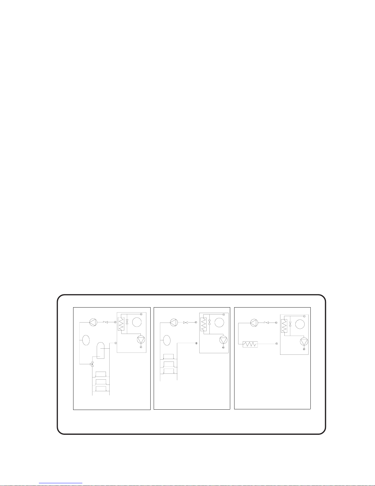
Typical circuits are as
Fig 2:3.
2:4 Heater Controls
This Heater uses a control specifically designed for
it and it has the following features:
A highly accurate Pool Thermostat , 16°C to 41°C
(60°F to 106°F)
A Heater Thermostat. Fixed f or P ool, 84°C, variab le
for Heating 60 - 82°C.
A Frost Thermostat which runs the Internal and Pool
Pump at 3°C or below but then fires the Heater
alone if the temperature has not risen sufficiently.
A Return Thermostat operating an internal bypass
for condensation reduction.
Fig 2:3
Heater
Pump
Pump
Zone Valve
Non return valve
Pump
Non return valve
Second water 2 water
heat exchanger
with Aquastat or similar
Pool Plus Heating and Hot Water
Pool Plus Heating
Pool Plus Spa
3 Way Valve
Expansion vessel
Expansion vessel
Heater Expansion
Vessel
4 litres
Heater
Heater Expansion
Vessel
4 litres
Heater
Heater Expansion
Vessel
4 litres
NB: Extra Expansion Vessel only required for very large systems. See Section 3:4
6
100 Gas Condensing Pool Heater01/06/02
Page 8

Terminal Position Minimum
Below window or vent 300 mm
Below gutter or pipes 75 mm
Below eaves 200 mm
Below balcony or roof 200 mm
From a window 200 mm
From vertical pipe 75 mm
From corners 300 mm
Above ground, roof or balcony 300 mm
From f acing surf ace 600 mm
From f acing terminal 1200 mm
From opening under a car port 1200 mm
V ertically from a terminal 1500 mm
Horizontally from a terminal 300 mm
An Over T emperature Thermostat (Overheat).
Internal Pump control with run on.
Pool Pump control with run on and out-of-season
exercise. (Requires external contactor)
Pool Temperature and Setting display . Engineer
selectable °C or °F.
User Indicators for P ool, Heating, Overheat, and
Service.
Engineer indicators of all switched outputs for
simple diagnosis.
Priority selection of Pool or Heating, engineer
selectable.
Memory of: Filter occurrences.
Sensor failure detection and indication.
Control self checking with fault indication.
For more detail see the
Commissioning (6:1) an
Fault Finding (7:1) sections
.
2:5 Gas Supply
The Local Gas Region should be consulted, at the
installation planning stage, in order to establish the
availability of an adequate supply of gas.
An existing service pipe must NOT be used without
prior consultation with the Local Gas Region, or by
a local Gas region contractor. An e xisting meter
should be checked preferably by the Gas region, to
ensure that the meter is adequate to deal with the
rate of gas supply required.
Installation pipes should be fitted in accordance
with BS.6891
Do NOT use pipes of a smaller size than the Heater
inlet gas connection.
3 FLUEING
Detailed recommendations for flueing are given in
BS.5440: 1. The f ollowing notes are intended for
general guidance.
1.
Be aware of the plume from the flue and the
wetting effect it has to adjacent property.
2.
The flue can be taken upwards, left, right or to
the rear of the appliance.
3.
The Heater is supplied with a Twin Pipe flue
suitable for terminating on an outside wall 1
metre away. More complex and length y flues
are possible, please consult the Flue Application
Guide for designs and the components.
4.
The Heater MUST be installed so that the
terminal is exposed to external air.
5.
It is important that the terminal allows the free
passage of air across it at all times.
T ab le 1.
IMPORTANT.
It is absolutely ESSENTIAL to ensure, in practice,
that products of combustion discharging from the
terminal cannot re-enter the building, or any other
adjacent building, through ventilators, windows,
doors, other sources of natural air infiltration or
forced ventilation/air conditioning.
If this should occur, the appliance MUST be
turned OFF IMMEDIA TELY and the Local Gas
Region consulted.
6.
The acceptable spacing from the terminal to
obstructions and ventilation openings are
specified in Table 1.
7.
Because the flue gases and terminal are at very
low temperature it is not necessary to fit a
Terminal guard to protect against burns. If a
guard is required for any other reason the
following is recommended.
For the T win Flue T erminal:
Model B (black plastic coated).
For the Single Flue T erminal:
Model H (black plastic coated).
All are available from:
Tower Flue Components Ltd.
Tower House.
Vale Rise.
Tonbridge
KENT
TN9 1TB
01732 351555
7
100 Gas Condensing Pool Heater 01/06/02
Page 9
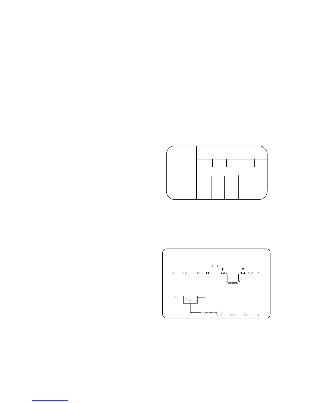
3:4 Sealed Systems
The Pool Heater is supplied with an Expansion
V essel (see Technical Data for details), a Pressure
Gauge, a Safety Valve and Filling Loop following the
guidelines given in the Code of Practice BS 7074 :1.
Please check that the supplied Expansion Vessel is
adequate for the proposed system. The f ollowing
procedure is suggested.
1.
Choose a vessel pressure by taking the static
head of the system, adding 0.3 bar, and taking
the nearest larger figure.
2.
Select the Vessel V olume from the tab le below
by finding the System Volume and V essel
Pressure.
3.
Choose that size or larger from the manufacturers’ range.
Vessel System Volume
Litres
Pressure 50 60 70 100 150
Bar
Vessel V olume
0.5
448812
1.0
8881218
1.5
8 12121824
T ab le 2.
A design as detailed below should be used for the
filling connection, it utilises a BS 1010 stop valve, a
double non-return valve and filling loop fitted at low
level and should be installed with the approval of
the local W ater Undertaking.
3:1 Air Supply
It is NOT necessary to have a purpose provided air
vent in the room or internal space in which the
Heater is installed.
Where the Heater is installed in a cupboard or
compartment no air vents are required. How ever the
User may wish to ensure that is ventilated to
provide air circulation.
3:2 Water Supply
The central heating system should be in accordance with the relevant recommendations given in
BS.6798, BS 7593:1992 and, in addition, for
smallbore and microbore systems - BS.5449:1.
The domestic hot water system, if applicable,
should be in accordance with the relevant recommendations of BS.5546.
Copper tubing to BS 2871:1 is recommended for
water carrying pipework.
The Mains W ater supply should be clean and able to
produce the required flow rate, see the T echnical Data.
New pipework must be flushed through before connecting.
The 100W incorporates a strainer and flow regulator
set to 8.5 l/m on the Cold W ater Mains Inlet, this can
be removed in countries with warm climates. The Inlet pressure should not exceed 10 bar , a reducer should
be fitted if it does.
Any hot water storage cylinder MUST be of the
indirect type and should preferably be manufactured
of copper.
The hot water cylinder, & ancillary pipework, not
forming part of the useful heating surface should be
lagged, to prevent heat loss and any possible
freezing, particularly where pipes run through roof
spaces and ventilated underfloor spaces.
Draining taps MUST be located in accessible
positions, which permit the draining of the whole
system, including Heater and hot water storage
vessel. Draining taps should be at least ½ in.
nominal size and be in accordance with BS.2879.
3:3 Condensate Drain
Refer to Fig. 1:5, 5:1, and 10:2
A condensate drain is provided on the Heater , this
drain must be connected to the household drainage
point, or soakaway on site. All pipework and fittings
in the condensate drainage system MUST be made
of plastic. Refer to British Gas publication “Guidance notes for installation of domestic condensing
boilers”
The drain outlet on the Heater is :
Polypipe, 21.5mm pushfit overflow pipe.
ALTERNATIVE METHODS OF FILLING A SEALED
SYSTEM
Method A
Method B
Hose Unions
Air Inlet
Valve
Temporary Hose
Mains
Water
Supply
Mains
Water
Supply
Test Cock
Stop Valve
Drain &
Fill
Double
Check Valve
Assembly
Drain &
Fill
Cistern &
Overflow
Pressure
Pump &
Reducing
Valve If
Required
Stop Valve
3:5 Electricity Supply
Wiring external to the appliance MUST be in accordance with the current I.E.E. Wiring Regulations
and any Local Regulations that apply .
The Heater is supplied for 230V ~ 50Hz. Single phase.
Fuse rating is 3A.
Fig. 3:4
8
100 Gas Condensing Pool Heater
20/10/03
Page 10
The method of connection to the mains electricity
supply MUST facilitate complete electrical isolation
of the Heater, pref erably by the use of a fused doub le
pole switch having a 3mm (1/8in.) contact separation
in both poles and servicing only the Heater and system controls.
The point of connection to the mains should be readily accessible and adjacent to the Heater , except that,
for shower room installations, the point of connection
to the mains MUST be situated outside the bathroom.
Note. Where a room sealed appliance is installed in
a room containing a basin or shower , the appliance,
any electrical switch or appliance control utilising
mains electricity should be so situated that it
cannot be touched by a person using the bath or
shower.
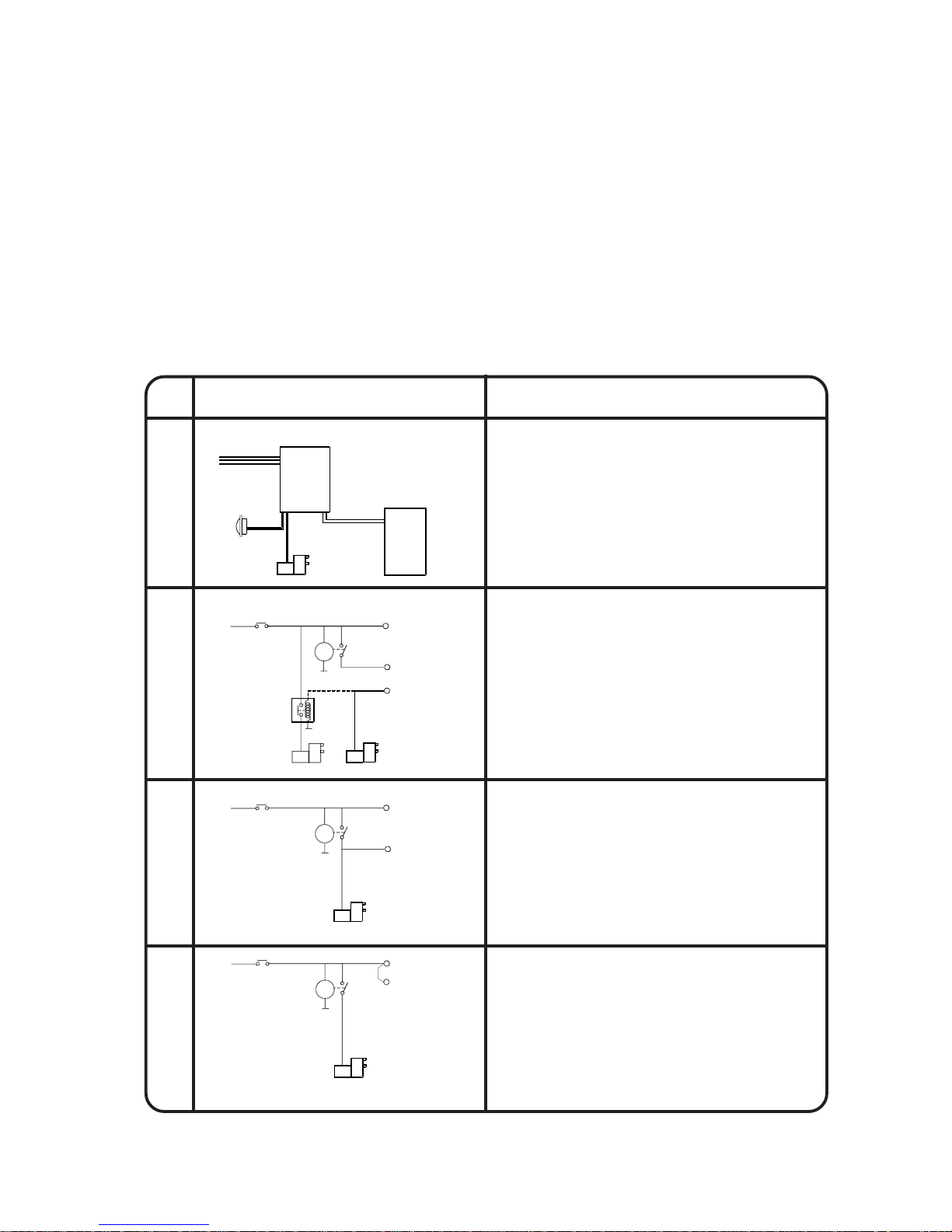
4. INSTALLATION WIRING
4:1 Wiring
The designs below are in order of preference, the
Quick Fit P ool Control Panel (CCP02) being the easiest, quickest and most comprehensive solution.
Design 4 is the least preferred as it does not utilise
all the features of the Heater Control.
Heater Connections are shown prefaced with ‘HTR’
in the diagrams below .
Fig. 4:1
9
100 Gas Condensing Pool Heater 01/06/02
LNE
Certikin Mk2 Oil Pool Heater
Pool Pump
Up to 16 A
Lights
Up to 6 A
Pool Pump
Rated to
suit pump
RELAY
T.S
> HTR, Permanent Live
> HTR, Pool Demand
< HTR, Pool Pump
Pool Pump
Up to 3 A
More than 3 A
Trip
L
N
N
T.S
> HTR, Permanent Live
> HTR, Pool Demand
Pool Pump
Trip
L
N
T.S
> HTR, Permanent Live
Pool Pump
Trip
L
N
> HTR, Pool Demand
DESIGN
#
NOTES
Takes full advantage of all the features of the Certikin
Oil Pool Heater.
Pool Pump control providing overrun and Frost Protection action.
Provides the fastest installation
Optional connections for Lights and Space Heating all provided.
1
2
3
4
Takes full advantage of all the features of the Certikin
Oil Pool Heater. Considerable installation time.
Pool Pump control providing overrun and Frost Protection action.
Optional Space Heating only available with more wiring.
Limited application of Certikin Oil Pool Heater.
Moderate installation time.
No Pool Pump control, Overrun or Frost Protection action.
Non-preferred application of Certikin Oil Pool Heater.
Moderate installation time.
No Pool Pump control, overrun or Frost Protection action.
Optional Lighting only available with more wiring.
Optional Space Heating only available with more wiring.
Optional Lighting only available with more wiring.
Utilising the CCP02 "Quick Fit" Oil Pool Heater Control
Optional Space Heating only available with more wiring.
Optional Lighting only available with more wiring.
T.S = Time switch
T.S = Time switch
T.S = Time switch
HTR = Oil Heater
HTR = Oil Heater
HTR = Oil Heater
CCP02
IMPORTANT: Remove link, Live to Pool Demand, in Oil Heater
IMPORTANT: Remove link, Live to Pool Demand, in Oil Heater
OR, Certikin Condensing 100 Pool Heater
OR, Certikin Condensing 100 Plus, Pool Heater
Page 11

4:2 Installation Of Heater
Suggested procedure:
1.
Position to suit system and terminal limitations.
2.
Mark & Drill Flue hole(s). (see Fig. 4:8).
3.
Remove the Electrical Tray and the Lower Case
from Heater module.
4.
Plumb tails to pool, gas heating and hot water .
5.
Test for leaks.
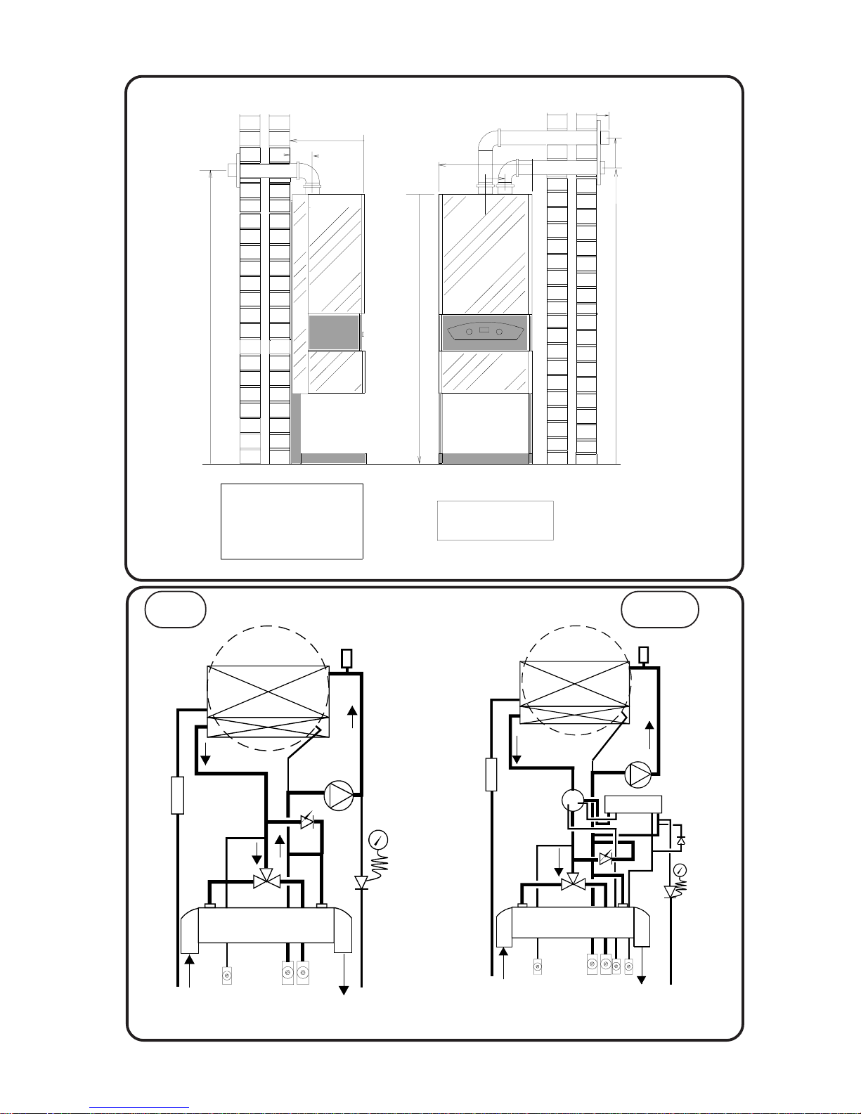
6. Replace the Low er Case and Electrical tray.
Space Required for Installation and Service.
Right or Left 30 mm 1 in.
Above 30mm 1 in.
Below 25mm 1 in.
In Front 450mm 18 in.
T able 3
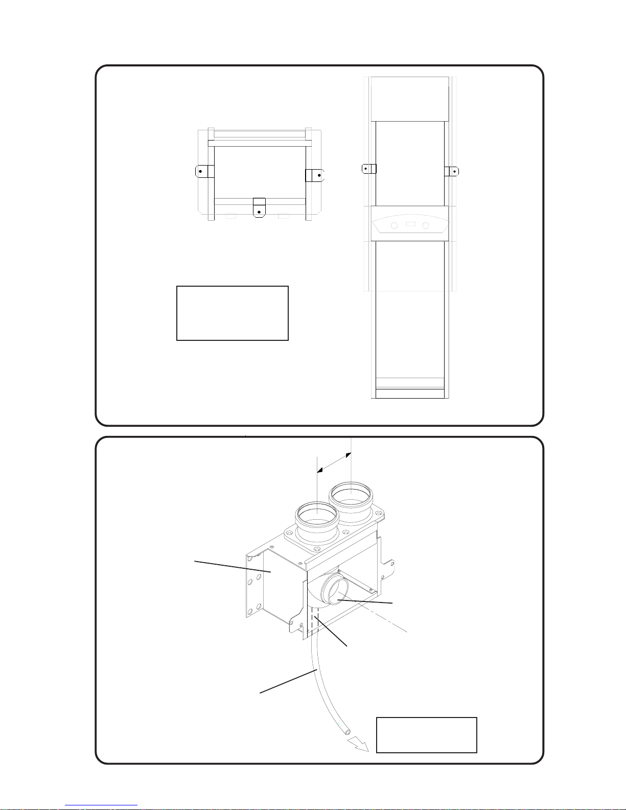
4:3 Fixing the Heater
1.
Position to suit system and terminal limitations.
2. Secure the frame, vertical, to the wall or floor
with the bracets provided..
3.
Mark the wall or ceiling for the flue exit points
and core drill the wall to give a 0 to 3 degree
slope down towards the Heater . The recommended core drill is 90mm for the Twin Pipe.
4:4 Terminal
The terminal can be fixed vertical or horizontal. The
flue pipe must always be connected to the extended
outlet of the terminal. The spacing is 120mm and a
core drill of 90mm is recommended.
See Fig. 4:8
4:5 Twin Pipe Assembly
All the Twin Pipe components for this appliance are
lightweight plastic and utilise a push-fit system.
V ery few f asteners are required and their use is
detailed on the instructions provided with the
components.
Important:
All Twin Pipe Installations must comply with the
following.
1.
The Flue pipe must slope back to the Heater by
three degrees (1 in 20) on all horizontal runs. The
air pipe can be above or below horizontal.
2.
Flue Pipes must be supported every 1000mm,
minimum.
3. All connections should be made with the Socket
end furthest from the heater.
4. Use the supplied CentraCerin or Silicone
Grease to ease the fitting of sections.
5.
The combined Equivalent Length of Air and Flue
should not exceed 22m horizontal, or 30m
vertical and including any terminal parts.
6.
The straight equivalent lengths of bends in a
horizontal design are as follows:
45 degrees, 1.3m.
90 degrees, 4m.
For more complex designs please see the details
provided with the components
It is recommended that:
1.
That 45 degree bends are always used with
vertical flues and where possible used in preference to 90 degree bends in horizontal installations.
2.
Straight Flue pieces may be reduced in length
by cutting square. It will ease assembly if the
cut edge is cleaned, chamfered and greased
before insertion.
4:6 Plumbing
Prepare the flow and return pipe work on the base of
the Heater. If the requirement f or Space Heating
exceeds 50,000 Btu/h (15kW), the Flow and Return
pipework from the Heater must be 28mm until the
heat load allows smaller bore pipework.
New pipework must be flushed through before
connecting.
4:7 Gas Connection
The 15mm gas connection point is provided. A
minimum of 20mb. (8in. w.g.) must be availab le at
the Heater inlet, with the Heater and other connected appliances firing. Check for gas soundness
(B.S. 6891: 1988) in pipework to Heater using a
manometer. Open the gas coc k. Gas soundness
within the Heater should be checked using sense of
smell and/or leak detection fluid. Check the burner
bar pressure with a manometer connected to the
control and adjust if required with the pressure
regulator.
10
100 Gas Condensing Pool Heater
01/06/02
Page 12
FIXING POSITIONS
TWIN FLUE POSITIONS
Fig.4:5
Flue Duct
Air Duct
100mm
Condensate Drain
Connection
(connects to drain point
on Flue Spigot Adapter)
Flue Spigot
Adapter
Drain Point
Twin Pipe Heater
Mounting Box
Assembly
Connects to condensate
drain point on Condensate
Drain Trap
11
100 Gas Condensing Pool Heater 01/06/02
PLAN VIEW
FRONT VIEW
Suggested fixings
3 into the floor OR
2 into the wall.
Fig.4:3
Page 13

4:8 Condensate Connection
The position of the plastic condensate drain pipe is
shown in
Fig 5:1
Where possible an internal termination of the
Condensate discharge pipework should be used.
Installation pipework must be in plastic to a suitable
drain location with a gradient of 2.5° (45mm/ meter
run) minimum. If connected to another drainage
trap, an air break is required between the Heater
drain and that trap. (
See Fig.10:2
). Internal runs
must be in a minimum of 19mm pipe. External runs
MUST be made in a minimum of 32mm pipe,
starting inside the building, and if possible insulated
to defer problems from freezing.
Whichever method is used it should be checked
during commissioning to prove there is a leakfree
working connection from the Heater to the drain. The
simplest way to do this is to carefully pour some
water into the Heater flue and check it emerges at
the drain.
The British Gas booklet “Guidance for the installation of Domestic Condensing Boilers” should also be
referred to .
5 SPACE HEATING
5:1 Typical Radiator System Design
General Principals
No special requirements are need for the selection
of radiators, normal sized radiators are acceptable.
The Manufacturer recommends using a programmable room thermostat, alternatively a separate room
thermostat and timeswitch can be used.
The Heaters include a pump overrun device so it is
essential that there is an open circuit for water to
flow between the flow and return. An Automatic
Bypass is incorporated in the appliance which
should be sufficient for most system designs.
The Heater includes integral frost protection. If the
temperature approaches freezing it will first try and
use the heat in the pool by running the Pool Pump .
If this does not raise the temperature it will run the
Heater. It will do this even when turned to Off, and
can only be inhibited by removing the P ermanent
Live supply to the Heater .
Thermostatic radiator valves can be used.
The Heater Pump is factory set at Speed 3 and
should not be alterered.
The Heater waterside is completely copper so all
good corrosion inhibitors are suitable. Inhibitor is not
required for Pool only applications .
The design temperature difference across the
Heater for optimum operating efficiency is 20°C. If
thermostatic valves or zone valves are used ensure
the minimum flow shown in the T echnical Data on
page 1 is possible.
5:2 Electrical Connections
WARNING: The appliance MUST be
earthed.
All wiring for the Heater and system controls MUST
conform to I.E.E. Wiring Regulations, and work
should be tested using a suitable meter, f or Earth
Continuity, Polarity, Short Circuit and Resistance to
Earth.
The supply must be through a common isolator, a
double pole 3A fused isolating switch with a contact
separation of 3mm minimum on both poles. The
cable used should be no less than 0.75mm
2
to
BS.6500 PVC, 3 core , and fixed ensuring the earth
connection is longer than the Live and Neutral.
Access to the Heater connections is made by
sliding out the bottom tray which is held by magnets, removing the single screw retaining the
Electrical Tray then releasing the screws retaining
the Chassis Cover .
The Heater internal wiring is shown in
Fig.5:2a &
Fig. 5:2b
.
Connections are made by push fit connectors
Connections are as follows :-
3 Way T erminal 4 Wa y T erminal
Earth Pool Pump
Neutral Neutral
Permanent Live Heating Demand
Pool Demand
A link is factory fitted between the Permanent Live
and the Pool Demand and should be remov ed if a
separate switched supply is provided f or P ool
Heating.
For systems using an external programmer , the
electrical wiring should follow the relevant control
manufacturer’ s recommendations, with the s witched
live from the controls returning to Pool Demand and/
or Heating Demand in the 4 way push-fit connector .
12
100 Gas Condensing Pool Heater 01/06/02
Page 14
INST ALLA TION DIMENSIONS
FLUE POSITIONS AND SERVICE ACCESS
Fig 4:8
13
100 Gas Condensing Pool Heater08/09/03
HEATER HYDRAULIC SCHEMATICS
Fig. 5:1
Safety Valve Drain
From Pool
Heating Flow
Heating Return
Fill & Drain
Condensate Drain
To Pool
Condensate Trap
Pump
Safety Valve
Diverter Valve
Auto Bypass
Valve
Expansion Vessel
Heat Exchanger
Pool Heat Exchanger
Auto
Air
Vent
Safety Valve Drain
From Pool
Heating Flow
Heating Return
Fill & Drain
Condensate Drain
To Pool
Condensate Trap
Pump
Safety Valve
Diverter Valve
Auto Bypass
Valve
CW Inlet
Three Way Valve
Water to Water
Heat Exchanger
Filling
Loop
Pool Heat Exchanger
Heat Exchanger
Expansion Vessel
Auto
Air
Vent
HW Outlet
100W100
Front View
C
L
100
Rear Flue
Side View
Twin pipe
Maximum 22m horizontal
90mm
90° bend = 4.0m
45° bend = 1.3m
Suggested core drill
Service Access
Front 450mm Above 30mm
Sides 30mm
Equivelant lengths: Minimum 200mm
Maximum 30m vertical
Side Flue
Flue
Air
390
110
500
1750
1850
1850
120
100
Page 15
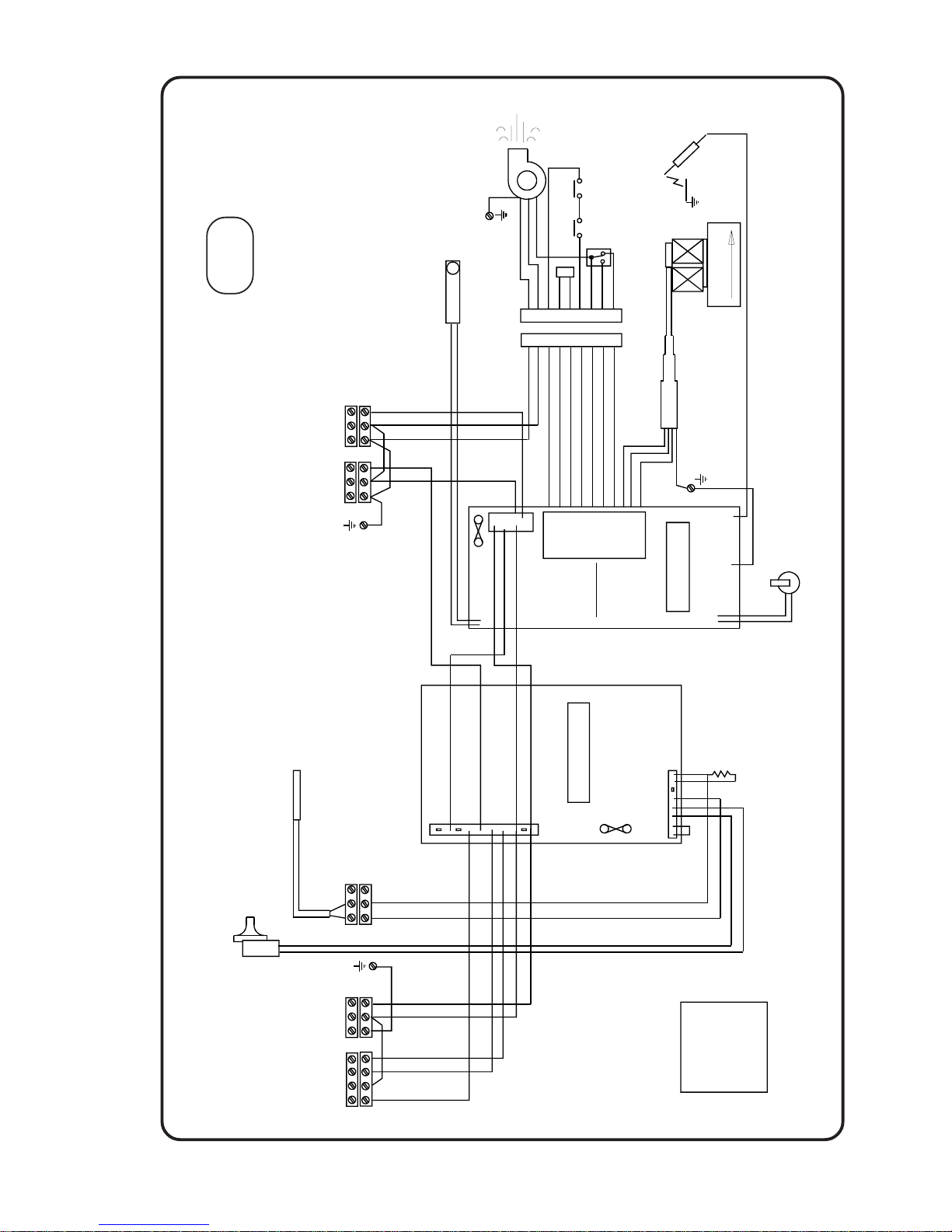
SCHEMATIC WIRING
Fig.5:2a
14
100 Gas Condensing Pool Heater 14/03/03
100
SUPPLY
E
N
L
HT
N
Ls
L
Lp
COM
AIR
NOAIR
O/H
O/H
SENSOR
SENSOR
12 Way connector
GV1
GV2
N
4 Core to Gas Valve
Fan
4 way Molex
10 way Molex
GV1 GV2
1 Amp 20mm
IGNITION BOARD
Or
Or
Br
Br
R
W
BkGyBr
R
Bk
Br
B
G/Y
G/Y
G/Y
B
G/Y
V
Gy
Br
R
OrWBk
Gy
V
G/Y
B
Brown
Red
Orange
White
Black
Blue
Grey
Violet
Green & Yellow
B
L
N
Pressure
Switch
O/H
P
o
o
l
P
u
m
p
Heating Demand
P
o
o
l
D
e
m
a
n
d
PUMP
E
N
Lp
CONTROL BOARD
INTERNAL
G/Y
E
N
N
2
5
0
m
A
A
S
L
R
C
POOL DMD
HTG DMD
HTR PUMP
POOL PUMP
BURNER
P
r
e
s
s
u
r
e
S
w
i
t
c
h
B
u
r
n
e
r
S
e
n
s
o
r
P
o
o
l
S
e
n
s
o
r
C
o
m
m
o
n
R
R
B
Or
Y
Yellow
W
B
Br
B
Gy
V
Sensor
Pool
3 PORT VALVE
B
R
O
W
N
RESET
SWITCH
Or
Br
Lockout Neon
14/03/03
Air Pressure Switch
NO
NC
S
e
n
s
o
r
Flue Stat
O/H Stat
M4733
10k
B
Page 16
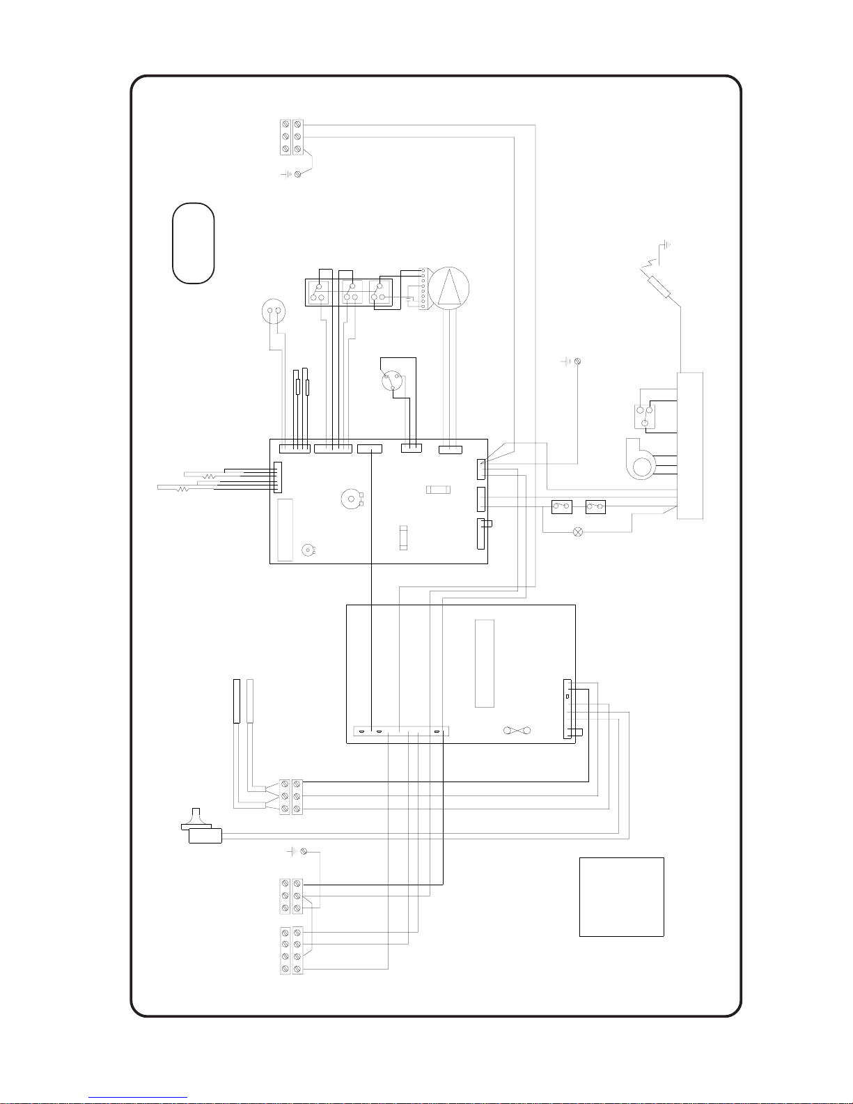
SCHEMATIC WIRING
15
100 Gas Condensing Pool Heater
21/10/03
Fig.5:2b
100W
DRIVER PCB
X1
X2
X3
X4
X5
X6
X7
X8X10
CH SET MAX
MODUREG
DHW
SENSOR
NC
NC
24V
FLOW SWITCHES
PUMP
CVI VALVE ASSEMBLY
1
8
NC
R
Y
W
R
V
G
y
Y
W
R
P
Br
B
HW SET MAX
R/B
Bk
G
y
/
B
k
NC
G
y
W
R
Or
B
B
Br
Br
B
Br
FAN
PRESSURE
OH STAT
LOCKOUT
NEON
FLUE STAT
W
W
OVERRUN
PUMP
230 V
CH
Bk
B
B
G/Y
G/Y
B
G/Y
Spark Electrode
230 V
Br
Or
Set Maximum CH Pressure
1
2
3
Fuse 315 mA
Fuse 2 A
P Pink
Set Minimum CH pressure
SWITCH
12 11 9 6
5
3
12
G/Y
8
Br
Cold
5
6
3
10k
10k
SUPPLY
E
N
L
R
Br
R
Or
W
Bk
Gy
V
G/Y
B
Brown
Red
Orange
White
Black
Blue
Grey
Violet
Green & Yellow
L
N
Pressure
Switch
O/H
P
o
o
l
P
u
m
p
H
e
a
t
i
n
g
D
e
m
a
n
d
P
o
o
l
D
e
m
a
n
d
CONTROL BOARD
G/Y
N
2
5
0
m
A
A
S
L
R
C
POOL DMD
HTG DMD
HTR PUMP
POOL PUMP
BURNER
P
r
e
s
s
u
r
e
S
w
i
t
c
h
B
u
r
n
e
r
S
e
n
s
o
r
P
o
o
l
S
e
n
s
o
r
C
o
m
m
o
n
R
R
B
Or
Y
Yellow
Y
W
B
Br
B
Gy
V
Sensors
Pool
Burner
Or
Br
Bk
3 PORT
E
N
L
VALVE
B
r
B
G/Y
01/06/02
Page 17

6. COMMISSIONING
6.1 General Information
For Systems with Space Heating
The elimination of air from systems is essential to
minimise the occurrence of heat exchanger and
general system noise.
Metal swarf and flux chemicals make a very aggressive mixture, the destructive nature of which
can be drastically reduced by flushing. Consequently this is a mandatory step in the commissioning procedure.
Low water content, fabricated Heaters are vulnerable to damage by air , particularly when the system
water is ‘hard’. (Contains a lot of dissolved calcium
salts). The result of this damage is evident in noisy
Heaters and reduced service life.
Removal of air from a system mainly takes place
when the water is stopping, starting or not moving
at all. It is removed most easily when it is in large
bubbles, but the action of the pump is to chop it up
so that it becomes a foam, which is extremely
difficult to remove.
Two or three second bursts on the pump at the
initial stage will reduce the risk of foam formation.
Sloping the pipe runs towards the vent points will
greatly aid air removal. Sloping pipes are not just a
feature of gravity systems but can greatly aid the
pumped system because air can move towards a
vent when the pump stops.
Air is dissolved in water but is released when
heated. Always run a system at maximum temperature for at least 15 minutes to enable this potential
problem to be removed during commissioning.
6.2 Procedure
MODEL 100 ONL Y :
If the Heater has just been filled
with very cold water, the b uilt in F rost Thermostat
could attempt to fire it, if it has a permanent live
and no switched live, this is completely normal. It is
recommended that the gas cock is turned off during
this early stage.
Pool Only Systems
There is an Automatic Air Vent inside the Heater,
ensure that the cap is open before filling with mains
water through the Filling Loop.
With the gas off, run the heater to circulate the
water and remove the air . T urning the supply on and
off will pulse the pump and help the air to rise to the
Automatic Air Vent.
When completely clear of air, re-pressurise and
remove filling loop.
Turn the gas back on. The Heater is ready f or use .
The Heater is fitted with automatic ignition and will
start when the gas cock is open, Mains is connected to the Heater and the controls are calling for
heat.
For the Model 100 only:
It has a built in delay, and
the Heater can be held off for 120 seconds. However, for commissioning purposes, switching off
using the System Isolating Switch will avoid the
delay.
For Systems with Space Heating
It is strongly suggested that the following stages of
commissioning are followed, and not an immediate
connection of all services. This procedure pre vents
substantial amounts of air being dispersed through
the system as small bubbles.
Carry out electrical tests as stated in Electrical
Connections if not already done so.
With all radiator valves open, fill the system from
the Filling Loop, but do not start the pump.
With the temporary hose connected, fill from the
mains supply , then follo w the procedure below .
Check for water soundness and rectify where
necessary.
DO NOT TURN ON GAS
Drain the system by opening all draincocks. This
will flush the system of flux and swarf.
Pour ¾ of the inhibitor in and fill the system with
clean water and vent air from radiators and
pipework.
Pour in all the inhibitor , and fill to required pressure
plus 0.3 bar to allow for venting.
Switch on the electrical supply to the Heater and
switch the programmer ON.
Switch OFF after about five seconds and vent all
points again.
Repeat this for 5 minutes.
Re-pressurise if required.
T urn on pump (do not turn on gas) and run for at
least 30 minutes.
Stop pump at five minute intervals and vent until no
more air can be removed and air noises are no
longer produced at the Heater. While the system is
venting check again for water soundness.
16
100 Gas Condensing Pool Heater22/07/03
Page 18

Rating Table(1040 Btu/ft³) (38.8 MJ/m³
)
kW
Btu/h sec/ft³ m³/2 mins
22
75064 49.9 0.0680
24
81888 45.7 0.0742
26
88712 42.2 0.0804
TURN ON THE GAS
Check for gas soundness (BS 6891) in pipework to
the Heater using a manometer.
Open the gas cock and after purging the system,
the Heater will light automatically .
Run the system at maximum thermostat setting.
Gas soundness within the Heater should be
checked using sense of smell and/or leak detection
fluid.
Continue running for 15 minutes, venting every 5
minutes.
The Main V alv e gradually raises the pressure to the
set point. Allow at least 60 seconds for the Model
100 and 100 seconds for the Model 100W for the
final pressure to stabilise. NB The Pilot has no
adjustment.
IMPORTANT. It is essential when setting the burner
pressure that the inlet pressure is at least 20 mbar
with the Heater and any other connected appliances
running.
Check the burner pressure is correct by using a
manometer connected to the control.
(See the
Datatable inside the cover , the c hart below and
Fig.6:2a & 6:2b)
The pump speed is set by the Manufacturer at £
and should not be changed.
Re-pressurise to required pressure.
With the system hot, check again for water soundness. Refit the case to the Heater . Add remainder
of corrosion inhibitor. If there is a Space Heating
system balance in the normal way to obtain even
heating of all radiators.
If fitted, set the cylinder thermostat to 60oC, or
lower if preferred.
Complete the Logbook and pass to the user when
explaining and demonstrate the operation of the
system. Their instructions are in the first pages of
this Installation Instructions.
Note: The Heater is fitted with a syphon trap that includes a blocked drain detection device. This is to
safeguard the Heater and help defer the effects from
the possible freezing of the condensate pipework in
extreme weather .
The user should be made aware of this feature and,
that in the event of blocked condensate pipework, for
example frozen condensate pipework, the Heater will
automatically stop functioning. It will start again as
soon as the blockage has cleared.
COMMISSION CHECK LIST (HYDRAULIC)
The key points which must be observed closely, are
shown below .
* With radiator valves and vents open fill the
system.
* Do not use pump. Do not light gas
* Check for and rectify leaks.
* Drain to flush system.
* Refill system, adding ¾ of the inhibitor .
* Do not light Heater .
* V ent all radiator and air release points.
* Run pump for 5-10 second bursts and revent.
* Do not light Heater .
* Run pump for at least 30 minutes.
* Stop at 5 minute intervals to vent.
* Continue venting until no more air noise can be
heard.
* Light Heater and run at max thermostat setting.
Continue for 15 minutes, venting every 5
minutes.
* Add remainder of inhibitor .
T able 6:2
17
100 Gas Condensing Pool Heater 20/10/03
Page 19
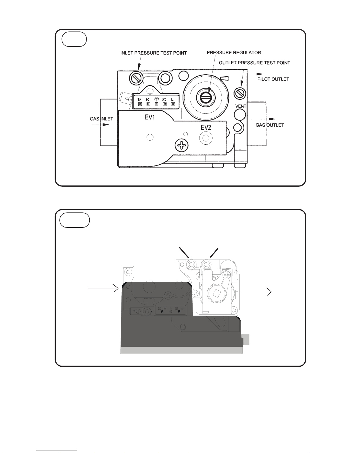
GAS VALVE
Fig 6:2a
18
100 Gas Condensing Pool Heater
01/06/02
IN
OUT
GAS INLET
GAS OUTLET
INLET PRESSURE POINT
OUTLET PRESSURE POINT
GAS VALVE
Fig 6:2b
100W
100
Page 20
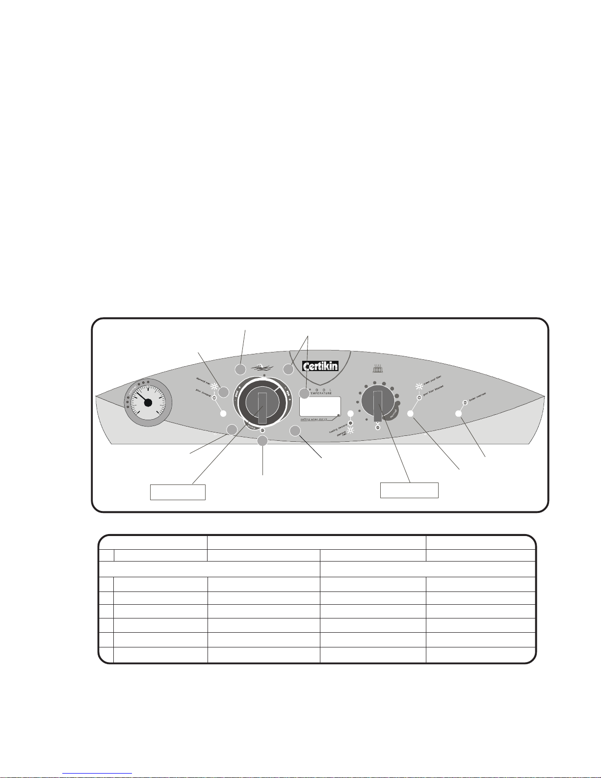
6.3 SETTING UP THE CONTROLS
It is recommended that you familiarise yourself with
the functions of the Control. These are detailed in
the
User Instructions Section
, and the
Heater
Control Section
.
There are two options that should be set to suit the
user and it also recommended that the Fault Logs
are cleared.
1. The display is factory set for
Fahrenheit Centigrade, it can be altered to
show Centigrade.
2. If the Heater is also providing Space Heat
ing/DHW , the f actory setting of Pool priority
may want to be changed to Heating priority .
Priority means, whichever is chosen has to
be up to temperature before it heats the
other.
These settings can be altered, and other data
viewed in ‘Setup Mode’
Setting Heating Knob On or Off Fascia Indicator
1 Heater temperature * Actual temperature Set temperature e.g 20 & 70
Factory setting Alternative
2 Display Units °F = Fahrenheit °C = Centigrade °C or °F
3 Priority P = Pool H = Heating P or H
4 Filter Pressure log # Number of Operations Resets to zero Yellow Filter LED On
5 Not used
6 Not used
7 Version Number __e.g. 010
* In this position with the Pool Temperature Control off, the Heater can be run for test purposes, if there is a Space
Heating demand, by turning On the Heating Temperature Control Knob.
# Reset the log by turning the Heating Temperature Control Knob On or Off.
T able 6:3. Contr ol Display in Setup Mode.
PROCEDURE T O ENTER SETUP MODE
T o enter Setup Mode turn both T emperature Control
Knobs to OFF.
The following must be carried out within 5 seconds.
1. Turn on the Mains supply to the Heater.
2. Turn the Pool Temperature Control Knob ON.
3. Turn the Heating T emperature Control Knob ON.
4. Turn the Pool Temperature Control Knob OFF.
5. Turn The Heating Temperature Control Knob OFF.
The Control is now in ‘Setup Mode’ and displaying
the Heater temperature. Additional data is displayed
as the Pool Temperature Knob is rotated.
See Fig.
6:3 & T able 6:3
Settings that can be altered are changed by turning
the Heating Temperature Control Knob On or Off.
To leave ‘Setup Mode’ and retain the new settings,
turn off the Mains supply for a few seconds at any
time.
Note: At power-up the Display is also used to show
fault conditions. If an unexpected display is shown
please check the Fault Finding Section 10:2.
Fig 6:3
ON
bar
0 4
2
1 3
u
s
e
r
i
n
s
t
r
u
c
t
i
o
n
s
i
n
s
i
d
e
u
s
e
r
i
n
s
t
r
u
c
t
i
o
n
s
i
n
s
i
d
e
100
s
e
e
i
n
s
t
r
u
c
t
i
o
n
s
2
3
4
5
6
7
1
Heater Temperature
Actual & Setting
Setting Knob
Adjusting Knob
Display units
°C or °F
Priority
P = Pool
H = Heating
Filter Log
Not Used
Ver sion
Number
Overheat LED
Filter LED
19
100 Gas Condensing Pool Heater
01/06/02
Page 21
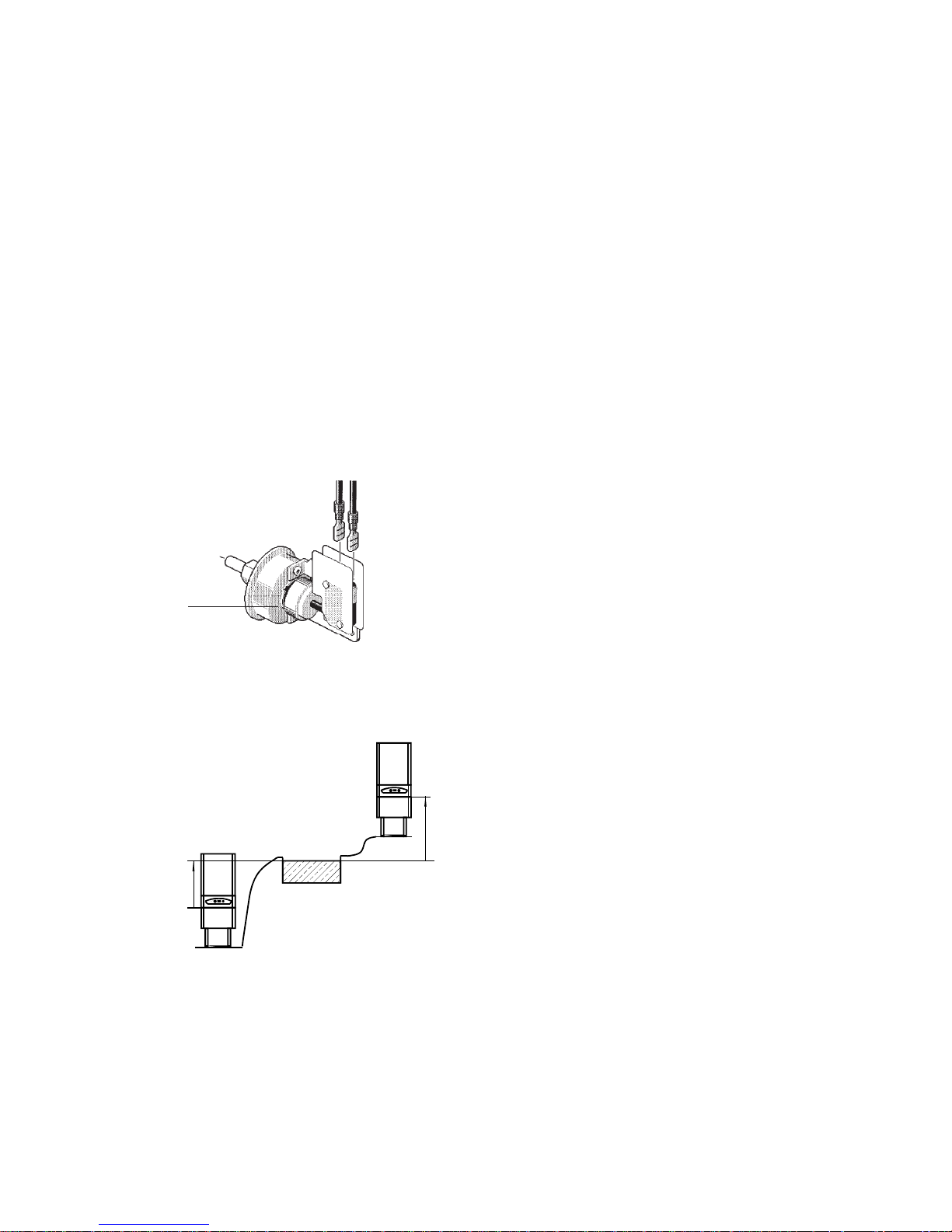
6.4 Pump Pressure Switch
The pressure switch, ensures that the heater operates
only when the filter pump is in operation. It is factory
set at 0.12 bar (1.75 PSI) for deck level installations.
When the heater is located below the level of the spa
or pool, it may be necessary to reset the pressure
switch to compensate for the no-flow static head. If it
is necessary to reset the pressure switch, we
recommend the following procedure:
PUMP PRESSURE SWITCH ADJUSTMENT
1. With pump and heater on, turn adjustment
knob clockwise until a click is heard from the
gas valve.
2. Turn adjustment knob counter clockwise ¼
turn.
3. Turn pump off and on several times.
Heater should shut off immediately. If it does
not, repeat steps above until proper
adjustments is made.
Adjustment
Knob
NOTE:
If heater is installed outside of the limits
shown below, a flow switch must be used in place of
the pressure switch when mounted and wired adjacent
to the heater.
TWO SPEED PUMPS
In some cases, the flow on the low speed is insufficient
to operate the heater. This is apparent when the
pressure switch cannot be further adjusted or if the
heater makes banging noises. In these cases, the
pump must be run at high speed when heating the
water.
CAUTION:
Do not operate the heater without the
functionof a properly adjusted pressure switch or flow
switch.
6.5 Responsibility
It is the responsibility of the Installer to ensure that
the Heater is properly commissioned. It is essential
that the commissioning procedures detailed in this
manual are carried out by a qualified engineer.
Fig. 6:4a
Fig. 6:4b
1.5 m Max
1.5 m Max
20
100 Gas Condensing Pool Heater
01/06/02
Page 22
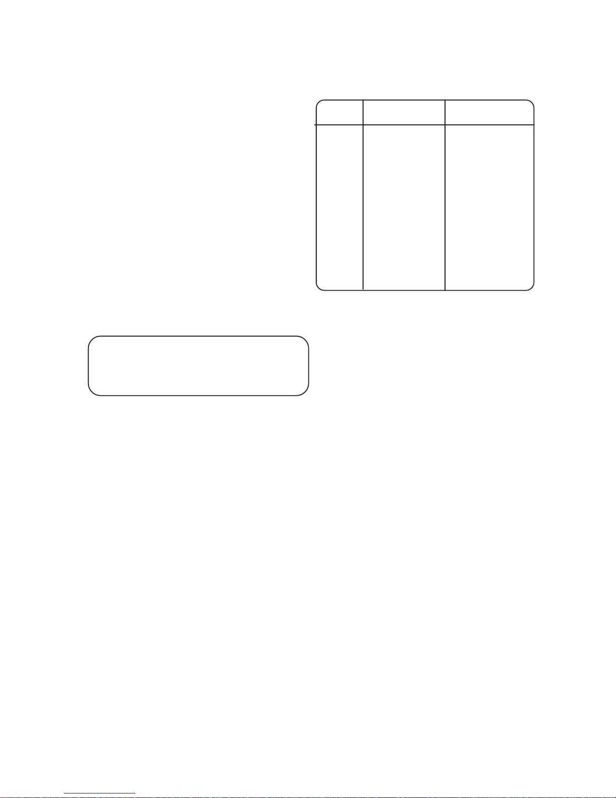
7:1:1 Control Fault Diagnostics
Before commencing a diagnosis it is recommended
that you familiarise yourself with the functions of
the Controls. These are detailed in the
Users
Instructions Section 1:4
and in
Heater Control,
Section 2:4
The Control will diagnose and display
most of its own faults.
Self Check
The Control does a full self check during power up.
It also briefly lights all the LEDs and the Temperature Display so they can be checked for operation.
Demand Inputs
The front panel LEDs for P ool Demand and Heating
Demand are triggered from the Mains Inputs and the
chosen Priority. If they are not lit check the supplied
voltage, connections and Priority setting.
Relay Outputs
LEDs on the Control Board, beside the relays, are
directly connected to the relay outputs and show if
there is an output voltage to the Burner, Internal
Pump or Pool Pump . If they are not lit check the
output voltages, if correct replace the board. If lit,
check voltage at the component, replace if correct.
7: FAULT FINDING
7:1 Heater Control
If the Heater fails to start, make the following checks .
1. Is the mains electricity supply switched On?
2. Is there a Demand for Pool or Space Heating?
3. For Space Heating is the Heater Thermostat
set to the desired temperature?
6. Check the fuses which should have been
fitted to the mains electricity supply to the
Timeswitch/Heater . If the fuse has blown.
Replace it. If it blows again, call a Service
Engineer.
7. Is the Filter LED lit? If it is, check Pool Pump
is running and the Filter is not blocked.
8. Is the Overheat LED lit? If it is press the Reset
on the Control Panel.
If the fault is not permanently corrected by one of
these actions it is likely that a component is faulty
and will need replacing. This should only be carried
out by someone competent to do so.
IMPORT ANT - E
LECTRICAL SAFETY
IT IS
ESSENTIONAL THAT BEFORE ANY P ANELS ON COMPONENTS
ARE
REMOVED FROM THE HEATER, THAT THE MAINS ISOLATOR IS
SWITCHED
OFF
.
Displayed Faults
The Control board detects and displays certain fault
conditions. The display alternates between two
codes.
Display Reason Action
Err / No
Control board fault.
Power Off then On
again. If not corrected
replace board.
Oc / thb
Boiler sensor
Check connections,
Open Circuit.
if correct, replace
sensor.
Oc / thp
Pool sensor
Check connections,
Open Circuit.
if correct, replace
sensor.
Sc / thb
Boiler sensor
Check connections,
Short Circuit.
if correct, replace
sensor.
Sc / thp
Pool sensor
Check connections,
Short Circuit.
if correct, replace
sensor.
Log
The Control keeps a log of the number of times the
Pressure Switch operates. These can be e xamined
and reset to zero in Setup Mode. The Temperature
Display units and Priority can also be checked and
altered in this mode.
Setup Mode
T o enter Setup Mode turn both temperature control
knobs to OFF.
The following must be carried out within 5 seconds.
T o enter Setup Mode turn both Temperature Control
Knobs to OFF.
The following must be carried out within 5 seconds.
1. Turn on the Mains supply to the Heater.
2. Turn the Pool Temperature Control Knob ON.
3. Turn the Heating T emperature Control Knob ON.
4. Turn the Pool Temperature Control Knob OFF.
5. Turn The Heating Temperature Control Knob OFF.
The Control is now in ‘Setup Mode’ and displaying
the Heater temperature.
The Display can now show additional data as the
Pool Temperature Knob is rotated.
See Fig 7:1 and
Table 7:1
Settings that can be altered can be changed by
turning the Heating T emperature Control Knob On or
Off.
To leave ‘Setup Mode’ and retain the new settings,
turn off the Mains supply for a few seconds at any
time.
21
100 Gas Condensing Pool Heater
10/03/03
Page 23
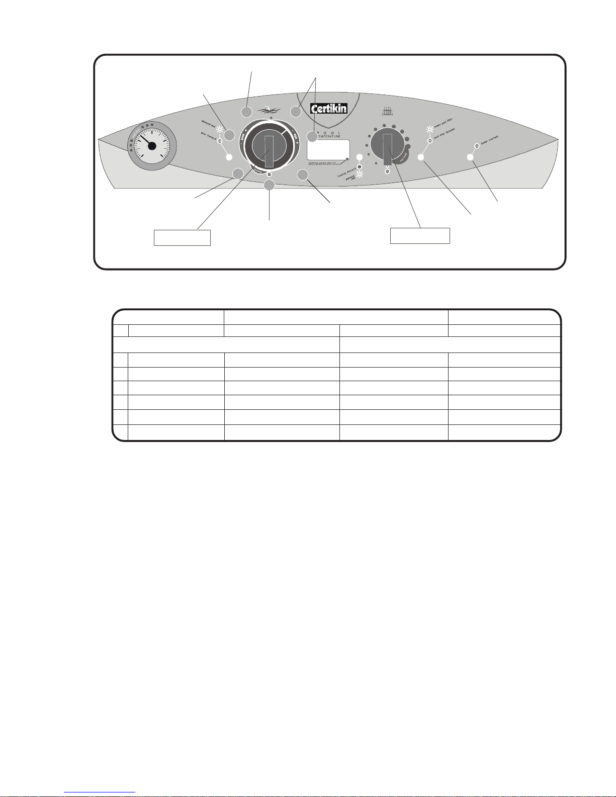
TABLE 7:1
FIG 7:1
ON
bar
0 4
2
1 3
u
s
e
r
i
n
s
t
r
u
c
t
i
o
n
s
i
n
s
i
d
e
u
s
e
r
i
n
s
t
r
u
c
t
i
o
n
s
i
n
s
i
d
e
100
s
e
e
i
n
s
t
r
u
c
t
i
o
n
s
2
3
4
5
6
7
1
Heater Temperature
Actual & Setting
Setting Knob
Adjusting Knob
Display units
°C or °F
Priority
P = Pool
H = Heating
Filter Log
Not Used
Ver sion
Number
Overheat LED
Filter LED
22
100 Gas Condensing Pool Heater 01/06/02
CONTROL DISPLAY IN SETUP MODE.
Setting Heating Knob On or Off Fascia Indicator
1 Heater temperature * Actual temperature Set temperature e.g 20 & 70
Factory setting Alternative
2 Display Units °F = Fahrenheit °C = Centigrade °C or °F
3 Priority P = Pool H = Heating P or H
4 Filter Pressure log # Number of Operations Resets to zero Yellow Filter LED On
5 Not used
6 Not used
7 Version Number __e.g. 010
* In this position with the Pool Temperature Control off, the Heater can be run for test purposes, if there is a Space
Heating demand, by turning On the Heating Temperature Control Knob.
# Reset the log by turning the Heating Temperature Control Knob On or Off.
Page 24

7.2 Ignition Faults
Model 100 Only
WARNING: BEFORE COMMENCING OR COM-
PLETING ANY ELECTRICAL WORK ON THE
APPLIANCE, IT IS RECOMMENDED THAT THE
BASIC SAFETY CHECKS FOR EARTH CONTINUITY, SHORT CIRCUIT , POLARITY AND RESISTANCE T O EARTH ARE MADE. ALL WORK
CARRIED OUT SHOULD FOLLOW GUIDELINES
LAID DOWN BY THE I.E.E.
The Ignition sequence in the Heater is straight
forward and faults can easily be traced if these
simple steps are followed.
Demand to Heat
Pool Thermostat closed
Boiler Thermostat closed
Ignition Control energised
Flue Stat closed
Overheat Stat closed
T rap not b locked
Pressure Switch open
Fan energised.
Pilot Ignition
Main Burner Ignition
If there is a request to heat the Pool, or if connected, the Space Heating, a mains signal will
appear at the POOL DEMAND or HTG DEMAND
connector in the Heater.
For Pool Heating
If the Pool Thermostat Board finds the P ool is
below the set temperature it will put mains on the
BURNER connection of the Pool Thermostat
Board.This is indicated by the LED on the Pool
Thermostat Board. This is connected to the Ignition
Board at its Ls, (Switched Live) connection and the
boiler will then start its ignition process.
For Space Heating (if connected)
If the Pool Thermostat Board finds the Pool is up to
temperature or it has been set for Heating Priority ,
it will put mains on the BURNER and HTR PUMP
connections. This is indicated by the LEDs on the
Pool Thermostat Board. The BURNER signal is
connected to the Ignition Board at its Ls, (Swiched
Live) connection and the boiler will then start its
ignition process. The HTR PUMP signal is used to
move the 3 way valve to Heating.
Ignition
Both the 100 and the100W follow the same sequence however there are indicators on the 100 to
show these steps. The description below uses the
100 to describe the process.
Lamps on the edge of the Ignition Board indicate
the stages in the ignition sequence. Please refer to
the lable inside the Heater .
Permanent live has to be connected to the L
terminal then the Power lamp lights .
A call for heat powers the Ls terminal and the
Running and Pump lamps light.
Provided the Flue Stat, Overheat Stat and Heater
are cold, the fan starts up. The pressure switch
detects the correct airflow and that the condensate
drain is not blocked then, switches over. This is
indicated by the Fan lamp illuminating.
The Pilot lamp illuminates, the pilot gas valve
opens and the Ignition Control Board provides a
spark at the pilot electrode.
(If the L and N supply are
reversed the Heater will not progress beyond pilot
ignition. This is indicated by the Phase Reversed neon
behind the knob lighting.)
The pilot flame is detected and the Ignition Control
Board stops sparking and then energises the main
gas valve and the Burner lamp is illuminated.
The pilot flame lights the burner, and it stays alight
until turned off by the control thermostat, system
controls, or in the case of a fault condition a safety
thermostat.
The flue thermostat will trip if the flue exceeds a
pre-set temperature. The ov erheat thermostat will
trip if the water flow rate is insufficient, both are
indicated by the Lockout lamp illuminating.
NOTE: The Heater has a b uilt-in dela y timer . It is
indicated by the Running lamp flashing.
For testing, switching the Mains Supply off for a few
seconds, then back on again will reset the delay.
Fault Diagnosis
The fault Diagnosis chart shows the normal and
fault sequences for the Ignition Board indicator
lamps.
T o diagnose a f ault, use the following procedure.
• Turn off the system Mains supply.
• Set all thermostats and timers to a call for
heat position.
• Turn on the system Mains supply and watch
the Ignition Board indicator lamps.
Compare the lamps with the diagnosis chart opposite to determine the fault and cause.
23
100 Gas Condensing Pool Heater20/10/03
Page 25
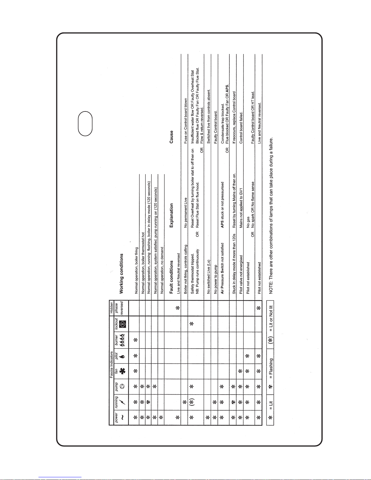
INDICATOR LIGHTS
Fig 7:2a
24
100 Gas Condensing Pool Heater
01/06/02
100
Page 26
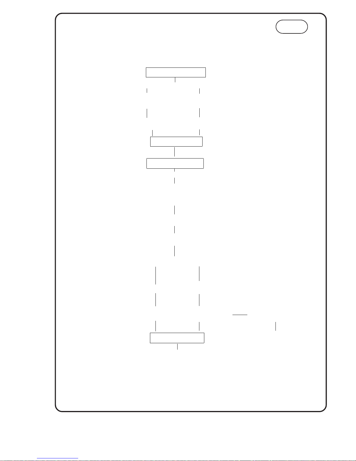
Fig. 7:2b
25
100 Gas Condensing Pool Heater20/10/03
By using the flow charts basic problems can be identified.
If the particular fault cannot be immediately identified, follow the charts from beginning to end
Before commencing, always check that the Mains is ON and the system controls are calling for heat, the gas cock is open.
Test the electrical system for short circuit, polarity, and resistance before attempting any electrical fault finding.
BOILER ACTION
Ensure Mains is ON.
Hot Water
required.
required.
Turn on any
Hot Water tap.
Ensure Clock/Thermostat
is set to call for heat.
Demand for heat
Fan and Pump start.
For HW Diverter Valve moves
to demand position.
Air Pressure switch
detects air flow.
Burner lights on
low flame.
Gas Valve opens for pilot.
Spark at electrode.
DHW: Burner to full rate.
CH: Low flame for 100 secs
then increases to full rate.
Flame modulates with heat demand.
Cycles ON and OFF if demand very low.
Demand Satisfied
USER CONTROLS
Operation Sequence
FAULT FINDING
Fault causes excess
temperature
Overheat trips
'Lockout' neon illuminates
A 'Demand' LED illuminates
Burner & Fan stop
100W
Page 27
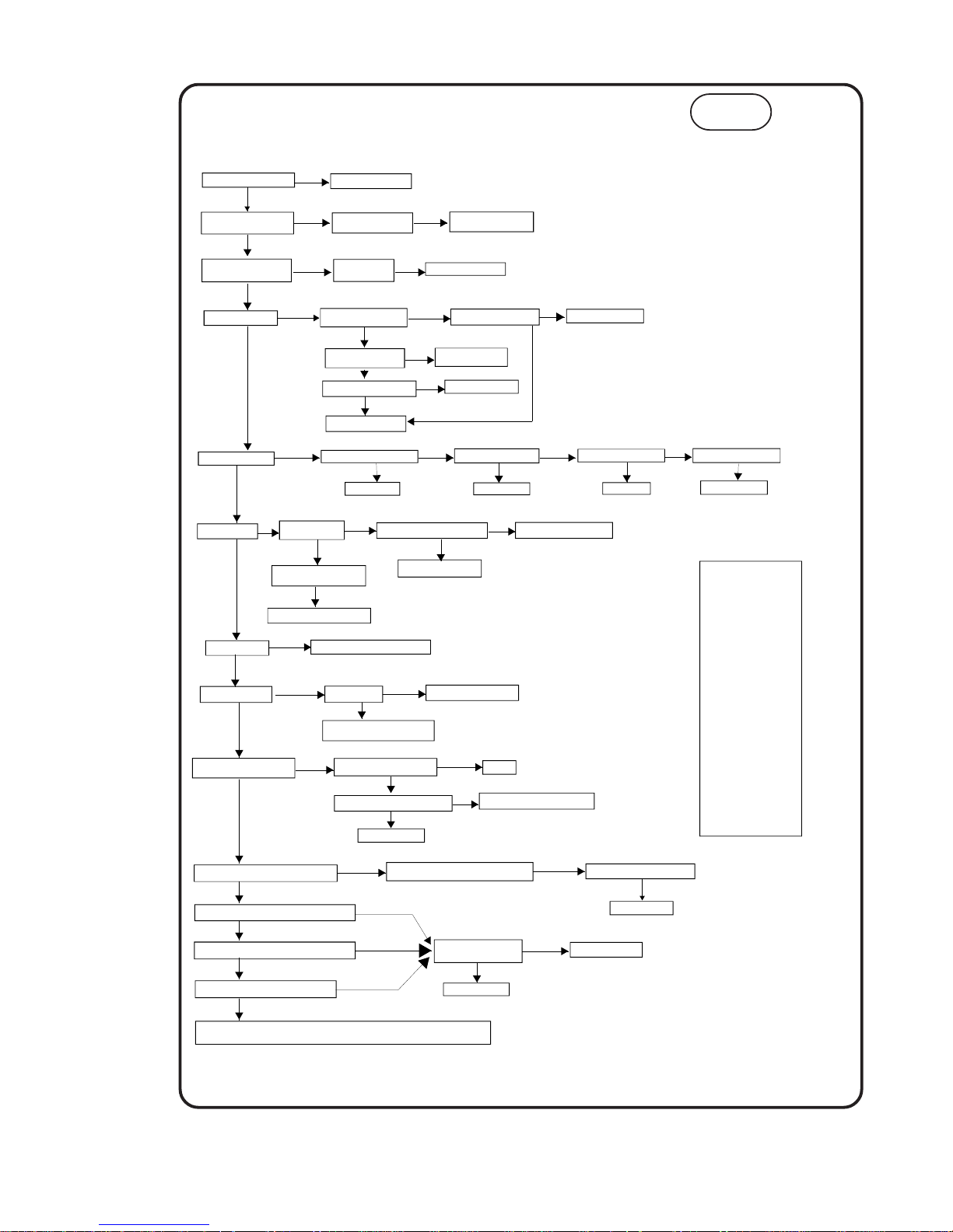
Fig 7:2c
26
100 Gas Condensing Pool Heater 20/10/03
Is 230V at L connection ?
Correct Mains Supply.
NO
Open any Hot mains tap.
Is the water flow rate OK ?
NO
YES
Remove, clean &
replace Flow Restrictor.
Check pressure and flow
rate of water supply.
Have the Diverter micro-
switches moved ?
Are Inlet & Outlet
pipes crossed ?
Replace diverter Valve.
Is there 230V to the pump
on its PCB terminals ?
YES
NO
NO
NO
Is the 2A PCB fuse OK ?
NO
Replace 2A PCB fuse.
NO
Are the micro-switches
operating electrically.
YES
NO
Replace the micro-
switch assembly.
Replace the main PCB
YES
Does the Fan start ?
Is the Pump free to rotate ?
Free or replace Pump
NO
YES
Does the pump start ?
NO
YES
Is there a spark ?
Has the O/H cutout tripped ?
Is there 230V to the Fan ?
NO
NO
NO
Has the Flue Stat tripped ?
NO
YES
YES
Reset or replace.
Reset or replace.
YES
Replace Fan.
Is there 230V from the CVI
Replace CVI board.
NO
Are the HT Lead & Electrode OK ?
Has the Pressure
Switch operated.
NO
YES
YES
NO
NO
Is there a blockage in the
Condensate Trap or tubes ?
Replace Electrode and Lead
Replace the CVI board.
NO
YES
Replace the Pressure Switch.
YES
YES
Does the Burner light ?
FAULT FINDING Hot Water Operation
NO
Is the Gas Inlet
pressure 20 mb
NO
Provide adequate Gas Supply
Replace CVI board, problem solved ?
if not replace CVI Valve
YES
Does Spark stop after Ignition ?
NO
YES
YES
Are the HT Lead & Electrode OK ?
Replace Electrode and Lead
NO
YES
Replace CVI board.
Is polarity of Boiler supply OK ?
NO
YES
Correct
Does Burner Flame increase to Maximum ?
Does the Flame reduce with water Flow Rate ?
Does the Flame reduce with the DHW Thermostat ?
Does the Flame stop before the O/H trips ?
YES
YES
YES
YES
Is the Thermistor reading
correct to Table A. ?
NO
NO
NO
NO
Replace Thermistor
NO
YES
Replace Main Board.
BOILER OPERATION SATISFACTORY
Is there upto 165mA on yellow lead to coil ?
NO
Replace Modureg Coil, now OK ?
YES
Start with system and boiler cold, with the power ON and no Hot Water taps open. Then Use a hot tap to operate the boiler.
0
20
10
30
40
50
60
70
80
90
33118
20198
12676
8176
5406
3657
2526
1780
1277
931
Temp °C
Ohms
TABLE A
YES
Has the Pilot lit ?
Check Pilot Injector, clean or replace.
NO
YES
Replace CVI
( CVI = Combined Valve & Ignition )
100W
Page 28
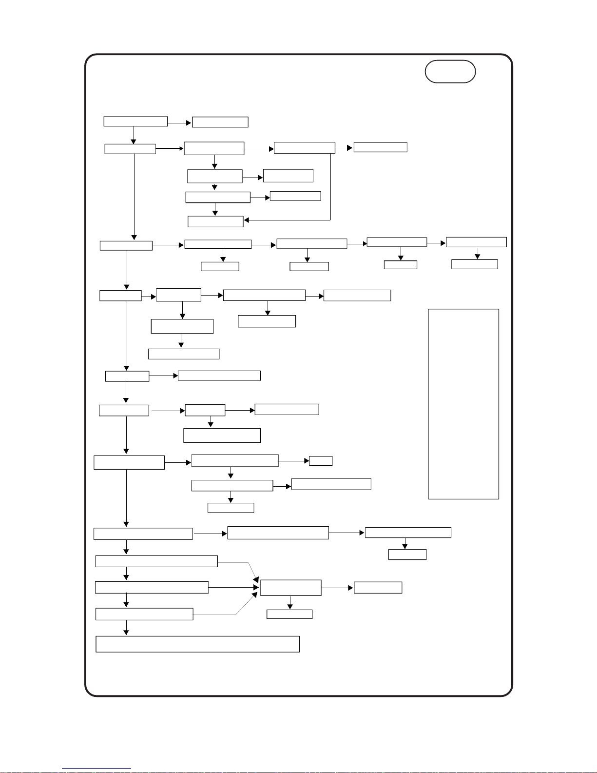
Fig. 7:2d
27
100 Gas Condensing Pool Heater 20/10/03
100W
Is 230V at L connection ?
Correct Mains Supply.
NO
Is there 230V to the pump
on its PCB terminals ?
Is the 2A PCB fuse OK ?
NO
Replace 2A PCB fuse.
NO
Are the micro-switches
operating electrically.
YES
NO
Replace the micro-
switch assembly.
Replace the main PCB
YES
Does the Fan start ?
Is the Pump free to rotate ?
Free or replace Pump
NO
YES
Does the pump start ?
NO
YES
Has the O/H cutout tripped ?
Is there 230V to the Fan ?
NO
NO
NO
Has the Flue Stat tripped ?
NO
YES
YES
Reset or replace.
Reset or replace.
YES
Replace Fan.
Is there 230V from the CVI
Replace CVI board.
NO
YES
YES
Does the Burner light ?
FAULT FINDING Pool or Space Heating Operation
Is the Gas Inlet
pressure 20 mb
NO
Provide adequate Gas Supply
Replace CVI board, problem solved ?
if not replace CVI Valve
YES
Does Spark stop after Ignition ?
NO
YES
YES
Are the HT Lead & Electrode OK ?
Replace Electrode and Lead
NO
YES
Replace CVI board.
Is polarity of Boiler supply OK ?
NO
YES
Correct
Does Burner Flame increase to Maximum ?
Does the Flame reduce as temperature rises to Maximum ?
Does the Flame reduce with the Boiler Thermostat ?
Does the Flame stop before the O/H trips ?
YES
YES
YES
YES
Is the Thermistor reading
correct to Table A. ?
NO
NO
NO
NO
Replace Thermistor
NO
YES
Replace Main Board.
BOILER OPERATION SATISFACTORY
Is there upto 165mA on yellow lead to coil ?
NO
Start with system and boiler cold, with the power ON and no Hot Water taps open.
Set the system controls to call for heat.
0
20
10
30
40
50
60
70
80
90
33118
20198
12676
8176
5406
3657
2526
1780
1277
931
Temp C
Ohms
TABLE A
YES
Is there a spark ?
Are the HT Lead & Electrode OK ?
Has the Pressure
Switch operated.
NO
NO
NO
Is there a blockage in the
Condensate Trap or tubes ?
Replace Electrode and Lead
Replace the CVI board.
NO
YES
Replace the Pressure Switch.
YES
YES
NO
Has the Pilot lit ?
Check Pilot Injector, clean or replace.
NO
YES
( CVI = Combined Valve & Ignition )
YES
Replace CVI
Replace Modulating Coil, now OK ?
Page 29

8. SER VICING
8.1 Heater Servicing
Health and Safety Statement :
This product contains no asbestos.
Routine
T o ensure continued efficient oper ation of the
appliance it is recommended that it is checked and
serviced at regular intervals.
The frequency of servicing will depend upon the
particular installation and usage but in general
once per year should be adequate.
It is law that any service work should be carried
out by Corgi registered personnel.
1.
Clean burner and combustion chamber .
2.
Check pilot and burner gas supply .
3.
Check condition of ignition sensing probe.
4.
Check Heater pipework joints for leaks.
5.
Check the case seals.
6.
Check condensate pipework for leaks.
7.
Check heat exchangers, and the flue and air duct
are clear of any obstruction, and not leaking.
8.
Check the F an and its seal.
9.
Check and clear the condensate exit on the
secondary heat exchanger by removing the
Condensate Outlet and the Inspection Covers
(Fig. 10:1).
10.
Check and clear the condensate syphon.
Follow the procedures given in Changing Components
for parts removal in addition to the following notes.
Heat Exchangers
Remove the panel in front of the secondary heat
exchanger to gain access to inner inspection
panels on the secondary and to view the primary
(the lowest inspection panel also gives a view of
the primary). Also view from beneath the primary .
Clean as required. If in doubt, drain the system and
remove for inspection.
Condensate Syphon
With a suitable bowl to catch the water , unscre w
the drain cap(s) on the underside of the Syphon
T rap and dr ain the water. Remo ve any solids and
replace the cap(s). (
See Fig 10:3
)
8.2 Changing Components
THERE ARE NO REP AIRABLE ITEMS, IF NO T
WORKING AN ITEM MUST BE REPLACED .
The Heater is in two major sections, the Case, and
the Electrical Chassis, The Major Components
Diagram shows where the items are to be found.
(pages 23-24)
Behind the Case
1. Fan.
2. Air Pressure Switch.
3. Flue Thermostat.
4. Control Sensor.
5. Overheat Cut-off Device.
6. HT Lead.
7. Pilot Assembly.
8. Burner.
9. Main Injector.
10. Combustion Chamber Insulation.
11. Primary Heat Exchanger.
12. Secondary Heat Exchanger.
For the 100W only
13. Pump Overrun Thermostat.
Servicing inside the Electrical Chassis
T o Remove the Electrical Chassis
• Disconnect the electrical supply from the
Heater and system.
For the 100W only:
Remove the single fixing screw.
• Slide the Electrical Tray forward a short wa y,
then lower onto the brack et if supprt
required.
• Remove the cover over the components.
• If complete removal required, disconnect all
the leads and remove the plastic nut holding
the Presssure Gauge retainer.
DO NOT STRAIN THE CABLES, USE THE SUPPORT PRO VIDED.
8.2.1 Control boards
• Lower the Electrical T r ay.
• Remove the screws that retains the inner
cover. Dissconnect all the leads from the
board to be changed.
Inside the Electrical Chassis
1 . Control Boards.
2. Gas Valve.
3. Pump
4. Safety Valv e
5. Pressure Gauge.
For the 100W only
6. Divertor Valve
7. Water to Water Heat Exchanger .
8. DHW Sensor.
9. Inlet Flow regulator and strainer.
28
100 Gas Condensing Pool Heater
20/10/03
Page 30
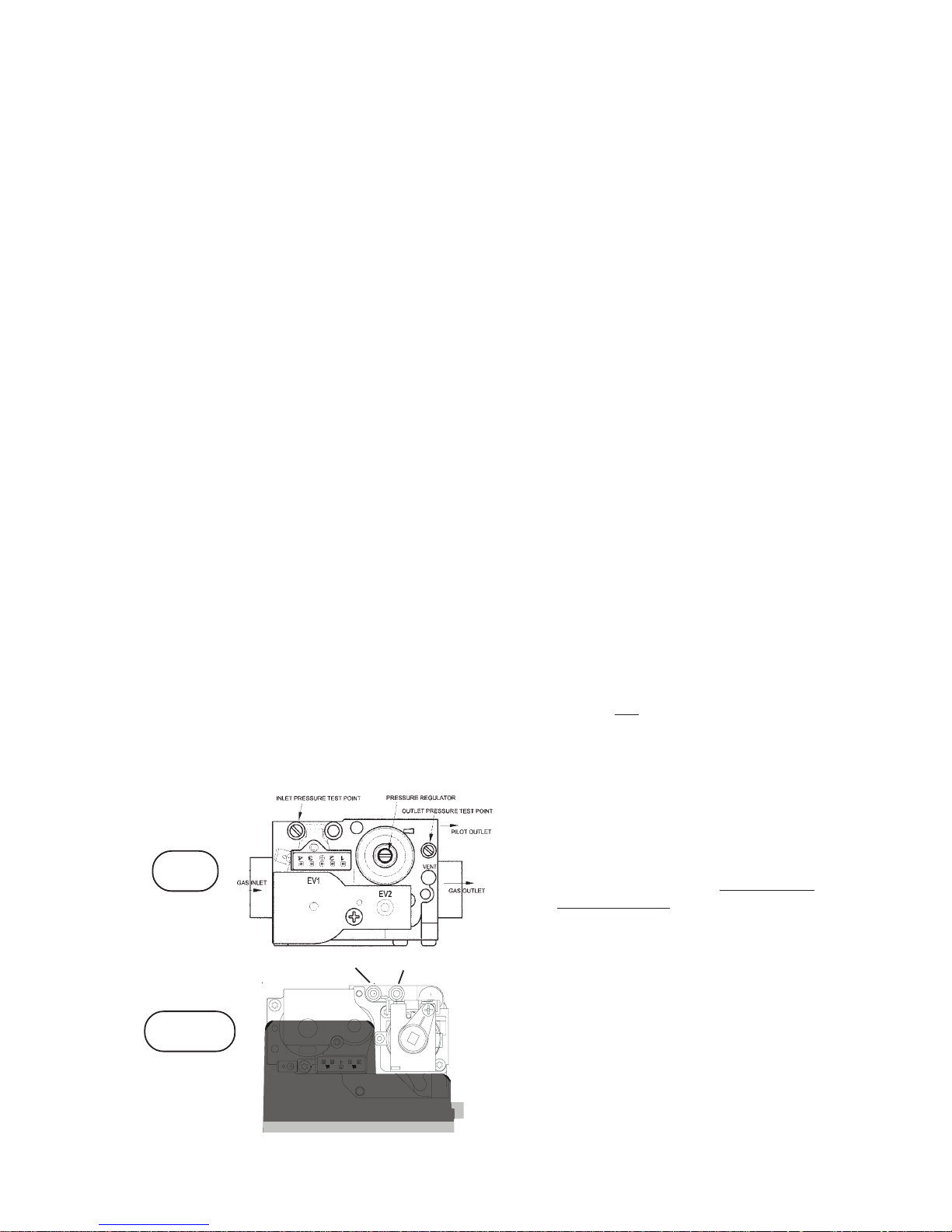
8.2.2 Gas V alve - 100 Model Onl y
• Lower the Electrical T r ay.
• Turn the Gas Cock off .
• Pull off the electrical connector from the Gas
Valve.
• Release the pilot feed tube.
• Undo the four shoulder bolts at each end of
the valve.
TAKE CARE TO SUPPORT THE VALVE AS IT IS
RELEASED.
• Replacement is the reverse.
• When secure, attach a manometer to the
burner pressure tapping on the right hand
side of the valve.
• The Pilot Adjuster is factory set.
Model 100W Only:
832.3 Sequence Controller
• Remove the Electrical Tray.
• Identify the CVI valve, the red pod beside it
contains the Sequence Controller.
• Prise off the multiway connectors from the
CVI Sequence Controller pod.
• Pull off the HT Lead from the Controller .
• Pull the pod awa y, and replace.
• Re-assembly is the reverse.
Fig 8:2.2
• Turn on gas and electrical supply .
• The gas valve slowly opens to its setting
ensure it has fully opened before adjusting.
• Set burner gas pressure with the gov ernor.
(see T echnical Data inside of cover .)
8.2.4 CVI V alve
• Remove the Electrical Tray.
• Turn the Gas Cock off.
• Pull off the red pod.
• Pull off the two leads from the Modureg
solenoid.
• Release the pilot feed tube (8mm AF).
• Undo the two screws holding the valve lower
retainer.
• Undo the gas cock.
• Undo the four shoulder bolts and remove the
flange to the gas cock.
• Release the CVI outlet connector , and
withdraw valve.
• Re-assembly is the reverse.
CVI Pressure Set Up
• Check Inlet pressure is at least 20 mbar
when operating.
• Remove the g rey co ver.
• Remove one of the yellow leads from the
Modureg and its grey plastic cov er .
• Attach a manometer to the outlet pressure
tapping.
• Set to Hot Water Only, turn on a tap and
check burner gas pressure is 1.8 mbar.
Adjust the 9mm brass nut on the Modureg to
correct.
• Replace the yellow lead and the boiler will go
to high fire, 11.3 mbar . Adjust with the nylon
7mm nut on the Modureg whilst pressing
down on its shaft.
• Replace the grey co ver .
• Ensure the system controls are calling for
POOL demand and set a Pool temper ature to
bring on the Heater. The Heater will fire at low
rate for 100 seconds. Adjust the small
potentiometer on the Driver board to 5.0 mbar.
• After 100 seconds the boiler will go to high
fire, adjust the large potentiometer on the
driver board to the desired maximum output,
factory setting 11.3 mbar.
For the Pool Thermostat Onl y:
• Remove the Control Knobs.
•
For the 100 Control Board Only:
• Release the Overheat Reset Switch.
• Slide out the board to be changed.
• Re-assembly is the reverse.
NOTE
Replace the rear restraint to the Pool
Thermostat board before re-fitting the board
connectors.
For the 100W Control Board Only:
• Adjust the burner pressures. See CVI
PRESSURE SETUP in CVI Valve section
below .
29
100 Gas Condensing Pool Heater
20/10/03
IN
OUT
INLET PRESSURE POINT
OUTLET PRESSURE POINT
100W
100
Page 31
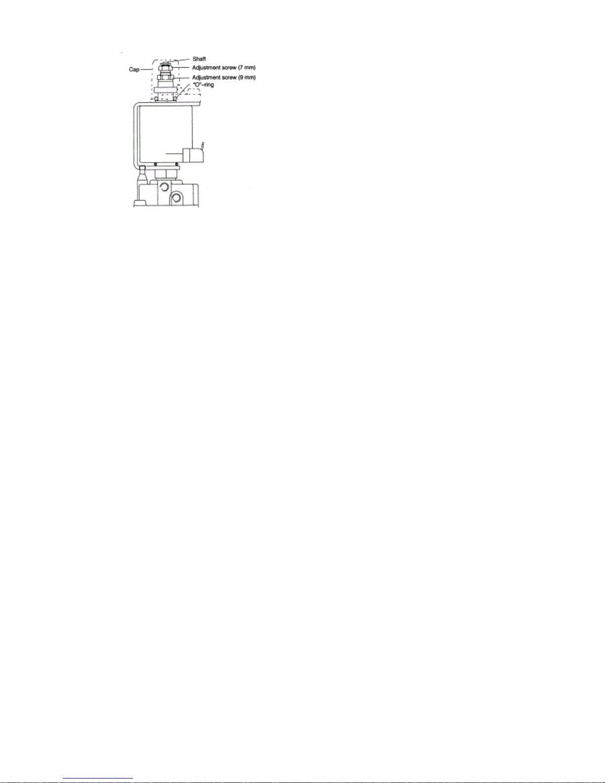
8.2.6 Pump
• Remove the Electrical Tray .
• Close the CH Flow and CH Return valves.
• Drain the boiler through the Fill and Drain
Valve.
• Disconnect the cable at the Pump including
those in the terminal strip opposite the
capacitor.
• Remove the terminal strip from the old pump.
• Undo the Pump nuts and remove the Pump.
• Re-assembly is the reverse,
• Note a brown and blue have a black sleeve
and these go to terminal 1 and 2
respectively. The black goes to 7.
• Ensure the fibre washers are in place.
8.2.7 Diverter V alve
• Remove the Electrical Tray .
• Close the CH Flow and CH Return valves.
• Close the DHW Cold In valve and open a
Hot tap to drain the pipework.
• Drain the boiler through the Fill and Drain
Valve.
• Remove the circlip on the Diverter V alv e to
release the switching head.
• Undo the five water connections to the valve
and remove.
8.2.12 Removing the Case
• Lower the Electrical T ra y.
• Undo the two M5 screws at the base of the
Case.
• Lift the Case straight up about half an inch
(12mm).
• Gently pull the Case straight forward off the
hidden studs at the top of the Heater. (Thecover
hangs on two studs in keyhole slots)
8.2.5 Pressure Gauge
• Remove the Electrical Tray .
• Loosen the Plastic Nut that holds Gauge
retainer.
• Squeeze the top and bottom latches on the
gauge, and push out of its retainer.
• V alv e off the Flow and Return connections.
• Release the pressure in the boiler .
• Unscrew the pressure sensor , it ma y need a
temporary plug to avoid leaks.
• Re-assembly is the reverse.
Fig 8:2.4
• Replace unit with new or factory exchange
unit.
• Re-assembly is the reverse, ensure the fibre
washers are in place.
8.2.8 Safety V alve
• Remove the Electrical Tray .
• Close the CH Flow and CH Return valves.
• Drain the boiler through the Fill and Drain
Valve.
• Remove the Pressure Gauge from the
Safety Valve.
• Undo the water connections to the Safety
Valv e and remo ve.
• Re-assembly is the reverse, ensure the fibre
washer is in place.
8.2.9 Water to W ater Heat Exchanger
• Remove the Electrical Tray .
• Close the CH Flow and CH Return valves.
• Close the DHW Cold In valve and open a
Hot tap to drain the pipework.
• Drain the boiler through the Fill and Drain
Valve.
• Remove pump and pipes for easy access.
• Undo the four water connections to the heat
exchanger and pull clear .
• Re-assembly is the reverse, ensure the fibre
washer is in place.
8.2.10 Flow Regulator and Strainer
• Remove the Electrical Tray .
• Close the Cold Water In valve.
• Open a Hot tap to drain the pipework.
• Remove the Mains Cold In V alv e.
• Carefully prise out the Flow Regulator and
Strainer (boiler side).
• Clean Strainer and restrictor.
• Re-assembly is the reverse.
8.2.11 DHW T emperature Sensor
• Remove the Electrical Tray .
• Remove the electrical connection from the
DHW Temperature Sensor and unclip from pipe.
• Re-assembly is the reverse.
30
100 Gas Condensing Pool Heater 01/06/02
Page 32

• Examine the sealing strip for damage and
replace if necessary.
• Place the Case somewhere safe from
damage
IMPORT ANT: F AILURE T O CORRECTL Y LOCA TE
THE APPLIANCE CASE COULD RESUL T IN
LEAKAGE OF COMBUSTION PRODUCTS
INTO THE ROOM.
8.2.13 Fan Assembly
• Lower the Electrical T ra y.
• Remove the Case.
• Undo the wing nut holding the Fan Protection
Hoop.
• Pull the electrical connectors off the Fan.
• Gently pull the pressure tubing off the
tappings on the Flue Hood.
• Undo the two screws holding the Flue Hood
and slide forward and aw ay.
• Re-assembly is the reverse.
8.2.14 Air Pressure Switch
• Lower the Electrical T ra y.
• Remove the Case.
• Pull the electrical connectors off the Air
Pressure Switch.
• Gently pull the pressure tubing off the both
tappings on the switch.
• Undo the M4 nut and wing nut holding the Air
Pressure Switch to its bracket on to the Back
Panel
• Lift off its studs and rotate out of its bracket.
• Re-assembly is the reverse.
8.2.15 Flue Thermostat
• Lower the Electrical T ra y.
• Remove the Case.
• To replace pull the electrical connectors off the
Flue Thermostat.
• To reset press Red Button.
• Re-assembly is the reverse.
8.2.16 Pump Overrun Thermostat
• Remove the Electrical Tray .
• Remove the Case.
• Note the three wire colours and positions.
• Pull the electrical connectors off the Pump
Overrun Thermostat.
• Undo the two M4 screws holding the Thermostat.
• Re-assembly using Heat Sink Compound is
in the reverse order .
8.2.17 Control Sensor
• Lower the Electrical Tray .
• Remove the Case.
• Unclip the sensor.
• Pull the electrical connectors off the Control
sensor.
• Re-assembly is the reverse.
8.2.18 Overheat Cut-off Device
• Lower the Electrical Tray .
• Remove the Case.
(To Reset, Press Red Button)
• Pull the electrical connectors off the Over
heat Cut-off device.
• Unscrew from its mounting.
• Re-assembly is the reverse.
• Lower the Electrical Tray .
8.2.19 Electrode and HT Lead
• Lower the Electrical T r ay.
• Remove the Case.
• To Replace pull off the HT lead from the Control
Board/Sequence Controller.
• Undo the left and right screws holding the
Front Burner Baffle.
• Remove the front baffle.
For the 100 Only:
• Release the tube nut holding the electrode to
the Pilot Burner.
• Carefully withdraw the Electrode and HT
Lead.
For the 100W Only:
• Push the Electrode towards the burner and
pull down and clear.
• Re-assembly is the reverse.
8.2.20 Pilot Assembly
• Lower the Electrical T r ay.
• Remove the Case.
• Undo the left and right screws holding the
Front Burner Baffle and remove . If access is
restricted also remove the lower baffle.
• Release the tube nut holding the electrode to
the Pilot Burner.
• Undo the Pilot tube from the Pilot Assembly
and gently lever downwards away from the
Pilot. It has to be removed and replaced
with the injector clipped into position.
Undo the two screws retaining the Pilot
Assembly.
• Re-assembly is the reverse
NB The pilot is not adjustab le.
31
100 Gas Condensing Pool Heater
20/10/03
Page 33

8.2.24 Combustion Chamber Insulation
• Lower the Electrical T r ay.
• Remove the Case.
• Remove the Front Baffle, then undo the four
M5 screws holding the lower baffle onto the
Back Panel
• Remove the Burner, as in 10.
• Undo the four screws holding the Chamber
to the Back P anel and lower downwards and
away .
• Replace the Insulation Panels in the
Chamber.
• Re-assembly is the reverse.
8.2.25 Primary Heat Exchanger
• Lower the Electrical T r ay.
• Remove the Case.
• Remove the front baffle.
• Remove or cover the Burner.
• Remove the Comb ustion Chamber.
• Unclip the Control sensor .
• Pull off the wires to the Overheat Cut Out
device.
• Drain the Heater of water .
• Undo the flow and return connections to the
Heat Exchanger and lower aw ay .
• Re-assembly is the reverse.
8.2.21 Burner
• Lower the Electrical T r ay.
• Remove the Case.
• Remove the Front Baffle.
• Remove the Combustion Chamber front by
releasing the four screws.
• Undo the Pilot tube from the Pilot Assembly
and gently lever downwards away from the
Pilot. It has to be removed and replaced with
the injector clipped into position.
• Pull off the HT lead.
• Pull the Burner forward off the two studs at
the rear.
• Remove the Pilot Assembly.
• Re-assembly is the reverse.
8.2.22 Main Injector
• Lower the Electrical T r ay.
• Remove the Case.
• Remove the Burner .
• Undo the Main Injector from the manifold.
• Re-assembly is the reverse.
8.2.26 Secondary Heat Exchanger
• Lower the Electrical T r ay.
• Remove the Case.
• Remove the Flue Thermostat.
• Remove the Fan Assembly.
• Drain the Heater of water.
• Undo the flow and return connections to the
secondary Heat Exchanger.
• Release the Condensate connection
clamping plate.
• Undo the four screws holding the Secondary
Heat Exchanger to the Back Panel and lift
away .
• Re-assembly is the reverse.
32
100 Gas Condensing Pool Heater 01/06/02
Page 34

9. PARTS
9.1 Spares
Ke y Item Part Number GC Number
1 Primary Heat Exchanger M0593
2 Secondary Heat Exchanger (17 kW) M0797
3 Burner (Model 100) M3727
3 Burner (Model 100W) M3728
4 Ceramic Board Set M1089 106 404
5 Fan Assemb ly M0910 106 435
6 Ignition Board (Model 100) M4750
6 Driver Board (Model 100W) M0614 173072
8 Contol Board M4735
9 Pool or Heating Sensor SPCOH2/002
10 Sequence Controller M0672 173066
11 Gas V alve (Model 100) M3783
12 Gas V alve (Model 100W) M0671
13 Air Pressure Switch M4176
Main Injector (4.1mm) M0919 106 386
14 Overheat Thermostat (Model 100) M3781 379 314
15 Overheat Thermostat (Model 100W) M0868 173068
Pilot Injector (Model 100) 7709 386 673
Pilot Injector (Model 100W) M0663 381656
Electrode (Model 100) 7710 386 744
16 HT Lead Assembly (Model 100) M3895
17 Electrode & Lead (Model 100W) M0666
Pilot Assembly (Model 100) 7716 381 865
Pilot Assembly (Model 100W) M0662 106437
18 Flue Thermostat 7717 379 308
19 Clip-on Sensor (22mm) M3338
20 Clip-on Sensor (15mm) M3337
21 Condensate T rap M3805
22 Safety Valve M0480 379831
23 Three Way V alve M0608 173071
24 Pressure Gauge SPCOH2/003
25 Expansion Vessel M0610
26 Plate Water to W ater Heat Exchanger M0612 106436
27 Grundfos Pump M0623 383722
28 Pool Water to Water Heat Exchanger M4374
29 Pool Pump Pressure Switch 651284
30 Bypass Valve M1091
31 Diverter Valve M4531
33
100 Gas Condensing Pool Heater
20/10/03
Page 35
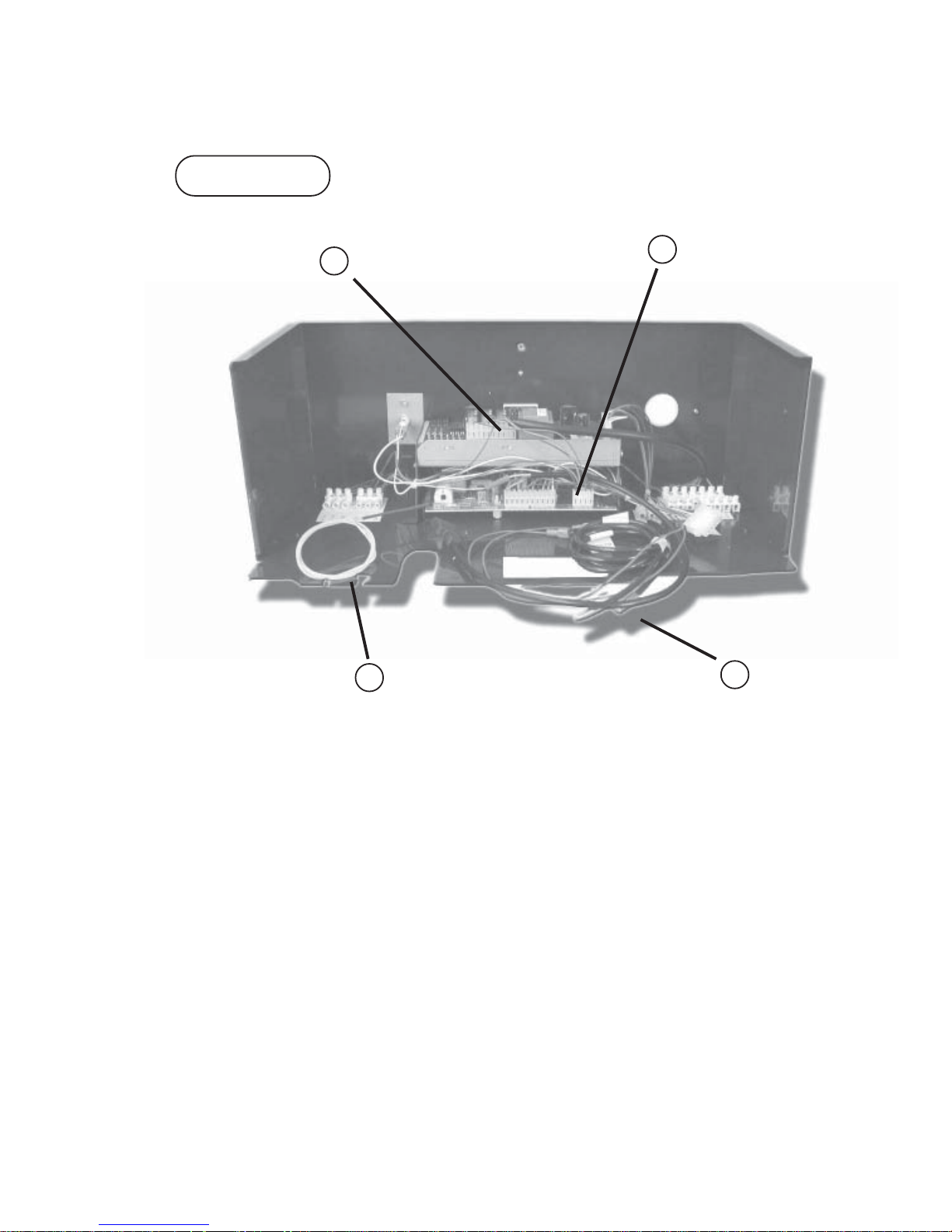
34
100 Gas Condensing Pool Heater 20/10/03
9:2 Electrical Components
100 & 100W
16
6
9
8
Page 36
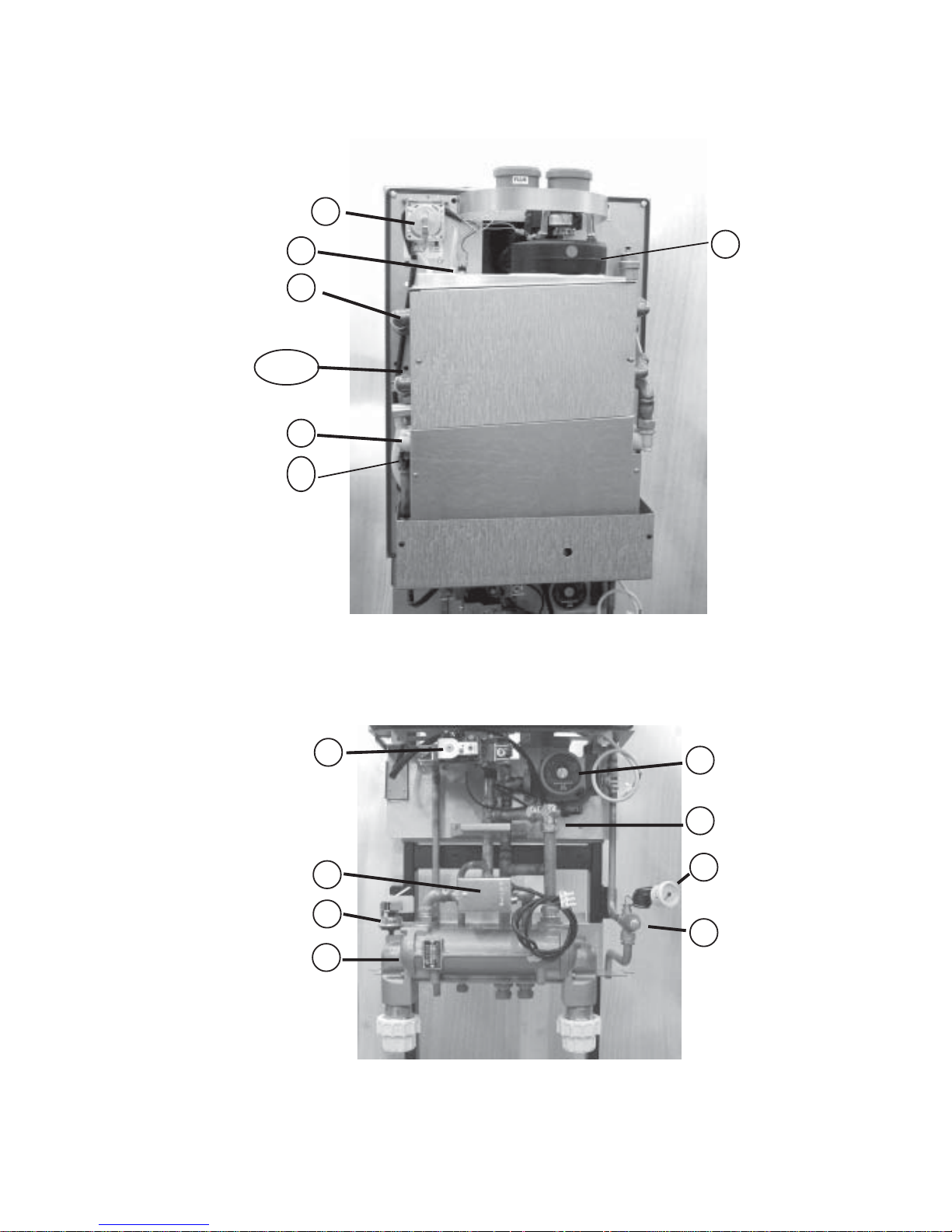
10 DIAGRAMS
10:1 Major Components
Fig.10:1
35
100 Gas Condensing Pool Heater
01/06/02
14/15
30
28
31
29
22
13
27
11
24
2
1
18
5
19
Page 37
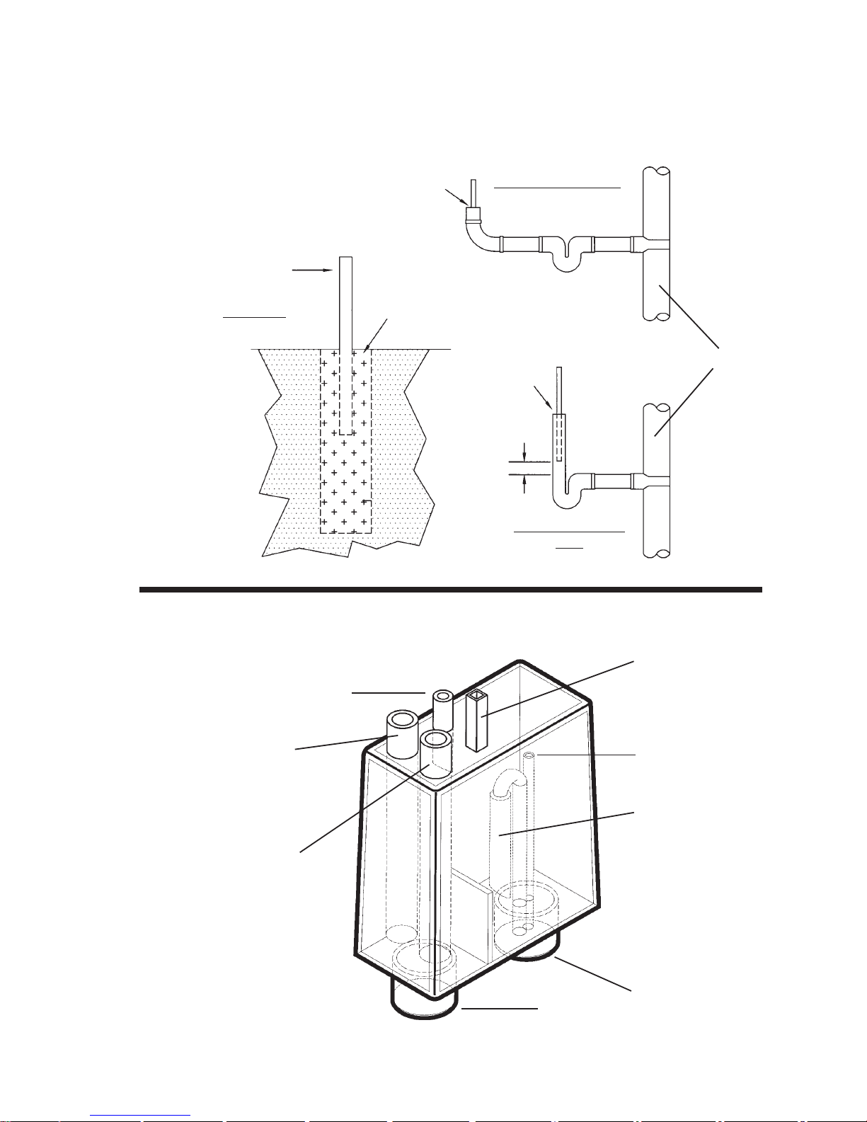
10:2 Example Condensate Disposal Methods
Fig.10:2
75mm Running Trap
Air Break
Strap-On Boss
1:20 Fall ( 2.5 Degrees )
Washing Machine
Trap
Air Gap
Air Gap
110mm Soil Pipe or Drain
Soakaway
Insulate against
freezing
150mm Land Drain
Filled with Gravel
750mm deep
Condensate
Drain from
Heater
Air Pressure Switch
pipe connection
Vent
Syphon
Connect To Waste
Drain Cap
Bypass
10.3 Condensate Drain Trap
Note: Internal - minimum 19mm pipe
External - minimum 32mm pipe
Condensate
Drain for
Twin Pipe Flue
Fig. 10:3
36
100 Gas Condensing Pool Heater 01/06/02
Page 38

M4728 20/10/03
 Loading...