

Page 1
WARNING: If the information in these instructions are not followed exactly, a fire or
explosion may result causing property damage, personal injury or death.
- Do not store or use gasoline or other flammable vapours and liquids in the vicinity
of this or any other appliance.
- WHAT TO DO IF YOU SMELL GAS
• Do not try to light any appliance.
• Do not touch any electrical switch; do not use any phone in your building.
• Immediately call your gas supplier from a neighbour's phone. Follow the gas
supplier's instructions.
- Installation and service must be performed by a Corgi registered installer. A page is
included on the inside back page of this booklet for recording commissioning and
service details.
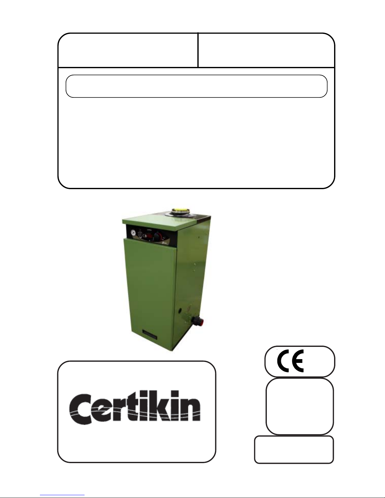
Operating, Installation and
Servicing Instructions for
Condensing
Pool & Spa Heaters
M2709
Models:
MB35S
MB50S
0087
Genie
Serial No:
Factory set for Natural Gas.
Can be Converted to Propane
with parts provided.
GB, IE, CH, ES, PT,
SI, SK & TR
Page 2
PERFORMANCE SPECIFICATIONS
GAS CATEGORY, TYPE AND SUPPLY PRESSURE II
2H3P
G20 @ 20 mbar
G31 @ 37 mbar
NATURAL GAS PROPANE
MODEL MB35S MB50S MB35S MB50S
Corgi Work Code 1036909 1036910 1036913 1036914
HEAT GROSS kW 38.0 51.5 38.0 51.5
INPUT Btu/h 129,650 179,100 129,650 179,100
NET kW 34.2 46.39 35.0 47.48
Btu/h 116,700 158,300 119,400 162,000
TYPICAL EFFICIENCY % gross 92 - 94 92 - 94 92 - 94 92 - 94
% net 102 - 104 102 - 104 102 - 104 102 - 104
HEAT kW 35.7 48.4 35.7 48.4
OUTPUT Btu/h 121,870 165,170 121,870 165,170
GAS RATE (NG, Propane) m3/h 3.45 4.64 1.43 1.9
MAXIMUM RATE, CO 120-150 80-120 130-160 100-130
COMBUSTION SETTINGS, NG, CO
2
9.2-9.4 9.0-9.4 10.3-10.5 10.0-10.3
OFFSET SETTING pA -3.0 -3.0 -3.0 -3.0
ORIFICE mm Not required 4.4 5.2
GENERAL SPECIFICATIONS
WATER CONTENT MB35S 3.0 Litres 0.66 gallons
MB50S 4.0 Litres 0.88 gallons
MINIMUM FLOW RATE 80 l/m (17.8 gpm)
MAX PRIMARY WATER PRESSURE 3 bar (45 psi)
INTERNAL PUMP SETTING Speed 3
MAXIMUM POOL TEMP Pool 41°C (106°F)
ELECTRICAL SUPPLY 230V 50Hz,FUSED AT 3A, 130W
PROTECTION LEVEL IP44
FLUE SYSTEM 80/125 PP, to a maximum Flue Equivelant Length of 20m
Condensing Pool Heater 22/12/08
TECHNICAL DATA
GB, IE, PT, CH, ES, PT, SI, SK, TR
Page 3

TECHNICAL DATA Inside cover
User Instructions 1
INTRODUCTION 3
Heater Location 3
Gas Supply 4
Conversion 4
Flueing 4
Air Supply 4
Outdoor Heaters 4
Condensate Drain 5
Pool Pump & Pipework 5
Winterisation 5
Electricity Supply 5
INSTALLATION OF HEA TER 6
Procedure 6
Outdoor Terminal 6
Flue Systems 6
Wall Terminal 6
Flue Examples 9
Roof Terminal 11
Plumbing 11
Pressure Switch 11
Gas Conversion 12
Gas Connection 12
Condensate Connection 13
Electrical Connection 13
Commissioning 15
Control Setup 16
Multiple Heater Kit 17
Wall Mounting Kit 19
FAULT FINDING 22
Operation 22
Safety Controls & Lockouts 22
Engineering Mode 22
Test Temperature Disp.Mode 22
Display Fault Codes 23/24
SERVICING 25
Routine Service 25
Changing Components 25
Spares 28
Heater Components 29
COMMISSIONING & SERVICE
HISTORY Inside back cover
List of Figures Page
Fig 1.0 Terminal Positions 4
Fig 2.0 Hydraulic Resistance Graph 5
Fig 3.0 Outdoor Terminal Fixing 6
Fig 3.1 Service Access &
Pipe Connections 7
Fig 3.2 Wall Terminal Dimensions 7
Fig 3.3 Outdoor Terminal Dimensions 8
Fig 3.4 Roof Terminal Dimensions 8
Fig 4.0 Wall Terminal Installation 9
Fig 4.1 Extended Wall Terminal
Installation 9
Fig 4.2 Extended Vertical Roof
Installation 9
Fig 4.3 Outdoor Terminal Installation 9
Fig 5.0 Pressure Switch 11
Fig 6.0 Throttle Adjustment 12
Fig 6.1 Orifice Position 12
Fig 6.2 Gas Valve Tappings 12
Fig 7.0 Condensate Disposal 14
Fig 7.1 Condensate Syphon 14
Fig 8.0 Heat Exchanger Air Vent 15
Fig 8.1 Pump Priming Button 15
Fig 8.2 Heat Exchanger Sight Glass 15
Fig 9.0 Controls 16
Fig 10.0 Multiple Heater Install 17
Fig 10.1 Multiple Heater Install 17
Fig 10.2 Multiple Heater Install 18
Fig 10.3 Wall Mounted Heater 19
Fig 10.4 Wall Mounting Dimensions 19
Fig 10.5 Wall Mounting Assembly 20
Fig 11.0Schematic Wiring 21
Fig 12.0 Electrode gap setting 25
Fig 13.0 Electrical Components 28
Fig 14.0 Heater Components 29
Section Page
Contents
Condensing Pool Heater 22/12/08
Page 4
Before Start Up
Keep heater area clear and free from combustibles,
flammable liquids and chemicals.
Pool water must be flowing through the Heater and the
Heater pressure gauge showing between 1.5 to 2.5 bar
for it to operate.
Quick Start
Check that the Electricity and Gas Supplies are on.
Turn on the Pool Pump. Turn on the Heater with the
switch on the Front Panel and set the desired
temperature with the Pool Temperature Knob. In a
few seconds the Heater will fire.
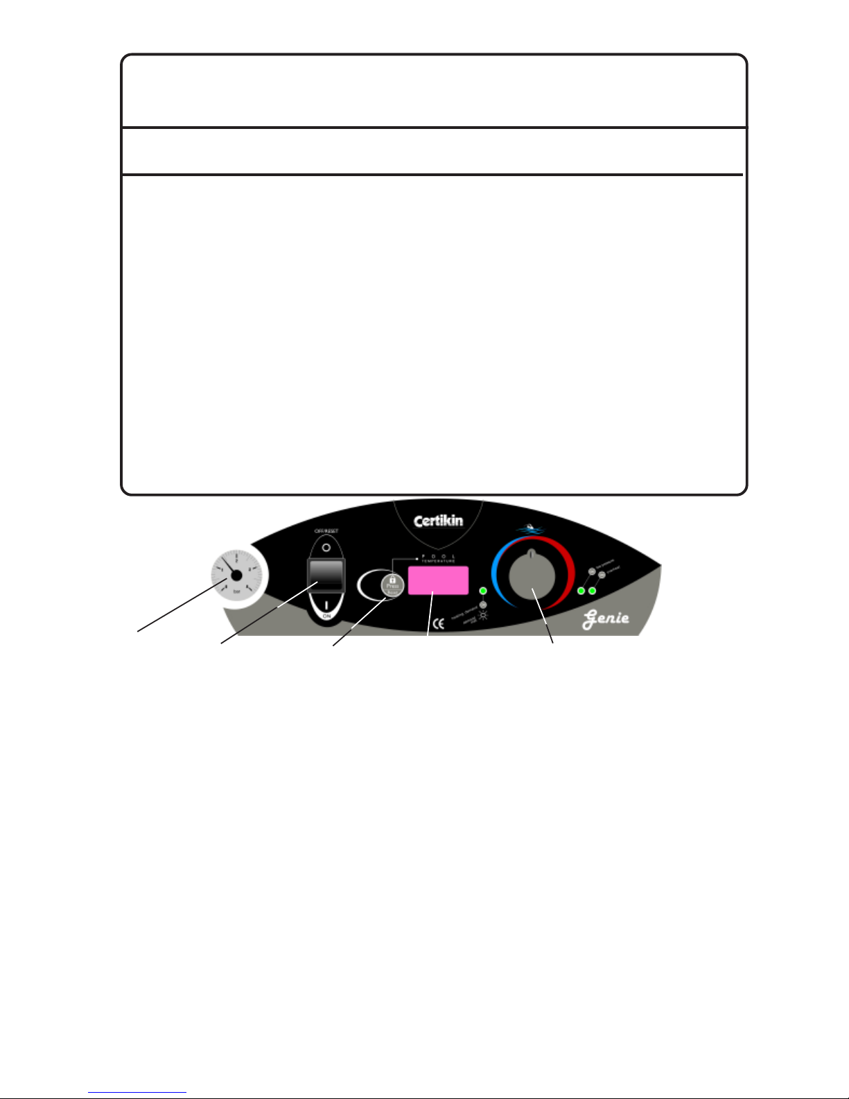
Summary of Controls (Left to Right)
Pressure Gauge - This should be between 1.5 to
2.5 bar, repressurise if too low.
ON/OFF Switch - Turns the Heater On and Off.
Lock/Reset Button - If it is pressed for 2 seconds
it locks the Set Temperature so the Pool Temperature Knob is inoperative. To unlock, press again for 2
seconds. When locked a short press flashes the Set
temperature.
It also resets Gas Control lockouts, GAS and OH2.
Pool Temperature Display - This normally
shows the Pool Temperature but also show the
Setting Temperature when the Pool Temperature
Control Knob is moved. The Display is also used for
commissioning and diagnostic purposes. (Page 16)
If the display alternates the temperature with ‘SEr’ it
is recommended that the Heater is serviced, it will
continue to function.
Condensing Pool Heater 1 22/12/08
Genie
USER'S OPERATING INSTRUCTIONS
FOR YOUR SAFETY - READ BEFORE OPERATING
WARNING: IF YOU DO NOT FOLLOW THESE INSTRUCTIONS EXACTLY, A FIRE OR EXPLOSION
MAY RESULT, CAUSING PROPERTY DAMAGE, PERSONAL INJURY OR LOSS OF LIFE.
This appliance is equipped with an ignition device
which automatically lights the burner.
BEFORE OPERATING after a prolonged time off,
smell all around the appliance area for gas. Be
sure to smell next to the floor because some gas
is heavier than air and will settle on the floor.
WHAT TO DO IF YOU SMELL GAS
* Do not try to light any appliance
* Do not touch any electric switch
* Do not use any phone in your building.
* Immediately call your gas supplier
from a neighbour's phone. Follow the
gas supplier's instructions.
* If you cannot reach your gas supplier,
call the fire service.
* Isolate the appliance with the Service
Cock inside. If this is not accessible,
isolate at the gas meter.
* Do not use this appliance if any part
has been under water. Immediately
call a qualified service engineer to
inspect the appliance and to replace
any part of the control system and any
gas control which has been damaged.
CAUTION: Propane gas is heavier than air and
will settle on the ground. Since it can accumulate
in confined areas, extra care should be exercised
when lighting Propane heaters.
WARNING: There are no user servicable items in
this appliance. Do not interfer with any sealed
components.
MPORTANT INFORMATION
Incorrect water balance will cause premature
failure of this heater. Such damage is not covered
under warranty. For additional information please
see page 3 of these Instructions.
On/Off Switch
Reset/Lock
Button
Temperature
Display
Pool Temperature
Control Knob
Pressure
Gauge
Page 5

Condensing Pool Heater 2 22/12/08
Pool Demand LED - Green
Off - There is no Pool Heating demand, pool heating
is off.
On - There is Pool Heating Demand and the Pool is
not up to temperature.
Flashing - The Pool Heating Demand is met, the
pool is up to temperature.
Pool Temperature Control Knob
16°C to 32°C (60°F to 90°F)
(Maximum is changed in Setup Mode, see Page 16)
Rotate clockwise to increase the Pool Temperature.
The Setting Temperature is shown whilst rotating
and for 3 seconds after.
To lock the required Temperature Setting see
Lock/Reset Button Page 1
Pool Pump Pressure
- Yellow LED, Display, Pool Temperature
On - If the pump is running and there is insufficient
pressure, possibly due to a blocked Pool Filter. The
Heater will not run.
Overheat - Flashing Red LED, Display “OH2”
Flashing - This indicates the Heater has overheated
and it has shutdown. Wait for the Heater to cool then
press the Lock/Reset Button to start the Heater
again. If this problem persists this should be investigated by a Service Engineer.
Overheat - Red & Yellow LED, Display “GAS”
On - This indicates the Heater Gas Ignition Control
has locked out. Press the Lock/Reset Button to start
the Heater again. If this problem persists this should
be investigated by a Service Engineer.
Condensate - Display “HI”
This indicates that the Condensate drain is blocked
and the Heater has shutdown. When the blockage is
cleared for the Heater will operate again.
Water Pressure Switch
A water pressure switch is provided in the heater to
shut off the burners in the event that water supply to
the heater is interrupted. The water pressure switch
should be checked and adjusted for proper operation by a qualified service person at the time of
installation, and thereafter checked at each service.
WARNING: Operation of the heater without water
circulation will cause rapid and severe damage to
the Heater.
Water Temperature Settings
The Heater is designed to provide the maximum
amount of heat to the pool up to one degree below
the set temperature. For that last degree it reduces
the power to maximise control. For certain installation designs, if the pool is used before it is up to set
temperature, the water entering the pool from the
Heater could be noticeably warmer than the pool.
This is not a fault but part of the design. It will reduce
for the final degree up to set temperature.
CAUTION
Elevated water temperature can be hazardous, and
the U.S. Consumer Product Safety Commission
recommends the following guidelines:
1. Spa or hot tub water temperatures should
never exceed 40°C (104°F). A temperature of
38°C (100°F) is considered safe for a healthy
adult. Special caution is suggested for young
children.
2. Drinking of alcoholic beverages before or during
spa or hot tub use can cause drowsiness which
could lead to unconsciousness and
subsequently result in drowning.
3. Pregnant Women Beware! Soaking in water
over 39°C (102°F) can cause fetal damage
during the first three months of pregnancy
resulting in the birth of a brain-damaged or
deformed child. Pregnant women should stick
to the 38°C (100°F) maximum rule.
4. Before entering the spa or hot tub, users should
check the water temperature with an accurate
thermometer; spa or hot tub thermostats may err
in regulating water temperatures by as much as
2°C (4°F).
5. Persons with a medical history of heart disease, circulatory problems, diabetes, or blood
pressure problems should obtain a doctor’s
advice before using pools or hot tubs.
6. Persons taking medications which induce
drowsiness, such as tranquilizers,
antihistamines, or anticoagulant, should not use
spas or hot tubs.
Cleaning
It is recommended that periodically the casing is
cleaned and sprayed with WD40 or similar liquid, and
any exposed threads are lightly coated in grease.
Service & Maintenance
It is recommended that the Heater is serviced every
2000 hours of operation, for normal use this is about
12 months. The control will alert when you when it
reaches this period by its display, ‘SEr’ alternating
with the temperature.
It is a mandatory requirement that any gas work
carried out must be by a Corgi registered engineer
with an appropriate accreditation.
Winterisation
As supplied the Heater includes a dose of inhibitor
and anti-freeze, sufficient to protect the primary heat
exchanger down to -5° C. If the Pool and Heater are
not going to be used for the cold winter months it is
recommended that the equipment is winterised.
Contact your pool installer for help with this.
Failure to winterise the Heater during a period of
freezing could cause damage to the Heater which
will not be covered by your warranty.
Page 6

Health and Safety document No 635, “Electricity at
Work Regulations”.
Detailed recommendations are contained in the
following British Standard Codes of Practice.
Codes of Practice.
BS.6798 Installation of gas fired hot water boilers of
rated input not exceeding 70kW.
BS.5440: Part1 and Part 2. Flues (for gas appliances of rated input not exceeding 60kW).
BS 6891 Specification for installation of low pressure
gas pipework.
BS5482:1 Code of practice for domestic butane &
propane gas burning installations.
Building Regulations Part L1.
IMPORTANT. It is important that no external
control devices are directly connected to this appliance - unless covered by these ‘Installation and
Servicing Instructions’ or otherwise recommended
by the manufacturer. If in doubt, please enquire.
Any direct connection of a control device not
recommended by the manufacturer could infringe
the Gas Safety (Installation & Use) Regulations, the
above regulations and the normal appliance warranty .
Manufacturer’s notes must NOT be taken, in any
way, as overriding statutory obligations.
Location of Heater
The Heater MUST be installed on a flat and level
floor, capable of adequately supporting the weight of
the Heater and any ancillary equipment.
Provision is provided for the heater to be fixed to the
floor.
It is IP 44 Rated and can be installed out of doors in
a suitable position. In all cases the choice of position
should take into account the flue, the plume and the
condensate drainage.
IMPORTANT NOTICE.
If the Heater is to be fitted in a timber framed building it should be fitted in accordance with the British
Gas publication ‘Guide for Gas Installations in
Timber Frame Housing’, reference DM2. If in doubt,
advice must be sought from the Local Gas Region of
British Gas.
The Heater may be installed in any room or internal
space. Particular attention is drawn to the requirements of the current I.E.E Wiring regulations and, in
Scotland, the electrical provisions of the Building
Regulations applicable to Scotland with respect to
the installation of the boiler in a room or internal
space containing a bath or shower.
Where a room sealed appliance is installed in a
room containing a bath or shower then the appliance
and any electrical switch or appliance control,
utilising mains electricity should be so situated that it
Condensing Pool Heater 3 22/12/08
INTRODUCTION
These Instructions cover a range of direct, floor
mounted, gas fired, condensing pool heaters which
are room sealed and fan assisted. The flue system
available is concentric, left, right, rear, and vertical,
all up to 20 metres ‘FEL’. There is also an Outdoor
Top terminal for use where the Heater is installed
out of doors. The ignition system is fully automatic.
There are two models with different outputs - see
the Technical Data on Inside Cover for details.
Both can be installed in multiples to obtain a larger,
combined output.
The casing is of green and black polyester powder
coated mild steel. The Heaters use a high performance stainless steel heat exchanger and are suitable for connection to pools using chlorinated and
salt chorinated water provided the following levels of
chemicals are maintained.
pH 7.2 to 7.8
Total Alkalinity 80 to 140 ppm
Calcium Hardness 200 to 400 ppm
Salt maximum 30000 ppm
Free Chlorine 1 to 4 ppm
All chemicals must be introduced and completely
diluted into the pool water before being circulated
through the heater. Do not place chlorine tablets or
bromine sticks in the skimmer, high chemical
concentrations will result when the pump is not
running.
Chlorinators must feed downstream of the heater
and have an anti-siphoning device to prevent
chemical back-up into the heater when the pump is
shut off.
NOTE: High chemical concentrates from feeders
and chlorinators that are out of adjustment will
cause corrosion to the heat exchanger in the
heaters. Such damage is not covered under the
warranty.
Gas Safety (Installation and Use)
Regulations, (as amended).
It is the law that all gas appliances are installed by a
competent person (e.g. a CORGI registered operative) in accordance with the above Regulations.
Failure to install appliances correctly could lead to
prosecution.
It is in your own interest, and that of safety, to
ensure that the law is complied with. The installation
of the Heater MUST also be in accordance with the
current I.E.E.. Wiring Regulations, the Local Building Regulations, Building Standards (Scotland), the
Bye Laws of the Local Water Undertaking, any
relevant requirements of the Local Authority, and
Page 7

Terminal Position Minimum
Below window or vent 300 mm
Below gutter or pipes 75 mm
Below eaves 200 mm
Below balcony or roof 200 mm
From a window 200 mm
From vertical pipe 75 mm
From corners 300 mm
Above ground, roof or balcony 300 mm
From facing surface 600 mm
From facing terminal 1200 mm
From opening under a car port 1200 mm
Vertically from a terminal 1500 mm
Horizontally from a terminal 300 mm
Condensing Pool Heater 4 22/12/08
cannot be touched by a person using the bath or
shower.
Where installation will be in an unusual location then
special procedures may be necessary and BS.6798
gives detailed guidance on this aspect.
A compartment used to enclose the Heater MUST
be designed and constructed specially for this
purpose. An existing cupboard, or compartment,
may be used provided it is modified for the purpose.
Details of essential features of cupboard compartment design, including airing cupboard installations
are given in BS.6798.
In siting the Heater, the following limitations MUST
be observed:
1. The position selected for installation MUST allow
adequate space for servicing in front of the boiler
and for air circulation around the boiler.
2. This position MUST also permit the provision of a
satisfactory balanced flue termination.
3. This position MUST also permit the provision of a
satisfactory connection to the condensate drain.
Gas Supply
An existing meter and pipework should be checked,
preferably by the Gas Supplier, to ensure that they
are adequate to deal with the rate of gas supply
required.
Supply pipes should be sized to suit installation and
obtain a working pressure of 20 mbar (NG), 37 mbar
(Propane) 29 mbar (Butane). Installation pipes
should be fitted in accordance with BS.6891.
A Natural Gas Heater must be connected to a
governed meter.
Conversion
For countries permitted to use different gasses the
appliance is supplied setup for the primary gas. It
can be converted to the alternative by the addition of
an Orifice which is supplied with the heater. See
page the inside cover for the data and Page12 for
conversion instructions.
Flueing
Only flue components specified by the Manufacturer
should be used with these appliances. Detailed
recommendations for flueing are given in BS.5440:
The following notes are intended for general guidance.
1. Be aware of the plume from the flue and the
wetting effect it can have to adjacent property.
2. The flue can be taken upwards, left, right or to
the rear of the appliance, but never downwards.
3. The Heater is supplied separate to the chosen
flue set. It can be fitted with up to 20 metres
equivalant length of Concentric flue, see the Flue
Section on page 8, 9 & 10 for examples and
parts selection.
Fig. 1.0
IMPORTANT.
It is absolutely ESSENTIAL to ensure in practice,
that products of combustion discharging from the
terminal cannot re-enter the building, or any other
adjacent building, through ventilators, windows,
doors, other sources of natural air infiltration or
forced ventilation/air conditioning.
If this should occur, the appliance MUST be turned
OFF IMMEDIATELY and the Local Supplier consulted.
Air Supply
It is NOT necessary to have a purpose provided air
vent in the room or internal space in which the boiler
is installed.
Where the boiler is installed in a cupboard or
compartment no air vents are required.
However the user may wish to ensure that it is
ventilated to provide air circulation.
Outdoor Heaters
These Heaters are certified for outdoor installation,
when equipped with the approved terminal.
WARNING: The heater shall not be located in an area
where water sprinklers, or other devices, may cause
water to spray through the cabinet openings and into
the heater. This could cause heavy internal rusting or
damage some electrical components, and this would
void the warranty.
It is recommended that periodically the casing is
cleaned and sprayed with WD40 or similar liquid, and
any exposed threads are lightly coated in grease.
Page 8

Genie Resistance
0.0
0.2
0.4
0.6
0.8
1.0
1.2
1.4
1.6
0 50 100 150 200 250
l/m
m head
Winterisation
Turn off the Mains electricty and Gas Supply.
As supplied the Heater includes one litre of Sentinel
X500 Inhibitor/Anti-freeze, this is sufficient to protect
the Heater down to -10°C. It is recommended that
this is maintained and so should be replenished if
there is a loss of primary water. See Fig 14.0
Draining the Heater can be achieved by fitting the
drain assembly in place of the double check valve/
hose connector. The Condensate Syphon can be
drained by removal of its Drain Cap. See Fig 7.1
Electricity Supply
Wiring external to the appliance MUST be in accordance with the current I.E.E. Wiring Regulations and
any Local Regulations that apply.
The Heater is supplied with a plug and lead for
230V ~ 50Hz. Single phase. Fuse rating is 3A.
The method of connection to the mains electricity
supply MUST facilitate complete electrical isolation
of the Heater, preferably by the use of a fused
double pole switch having a 3mm (1/8in.) contact
separation in both poles and servicing only the
Heater and its controls.
The point of connection to the mains should be
readily accessible and adjacent to the Heater.
Note. Where a Heater is installed in a room con-
taining a pool or shower, the appliance, any electrical switch or appliance control utilising mains
electricity should be so situated that it cannot be
touched.
Condensing Pool Heater 5 22/12/08
Condensate Drain
See Fig. 7.0, and 7.1
A 75mm condensate trap is provided on the Heater
and is satisfactory when connected to Soakaways,
Gullies, Rainwater Pipework and Internal Drainage
systems. All pipework and fittings in the condensate
drainage system MUST be made of plastic, unless
they carry other liquid waste. No other materials
may be used. The pipework should be insulated if
run out of doors.
The drain outlet on the boiler is :
1¼”or 40 mm Hunter waste pipe.
Pool Pump & Pipework
The Heater is an indirect design and uses two very
high performance heat exchangers. The pool water
passes through the Secondary, the water in the
Primary is completely seperate. The Heaters controls modulate the input when approaching the set
temperature for greater accuracy and economy. It is
recommended that pool pump overrun is used to
maximise the life of the Heater.
If a new pump is being fitted consult the Pressure
Loss graph (Fig 2.0) to determine its size.
The Heater is provided with both 1½” and 50mm
plastic pool connections. As built the connections
are ‘From Pool’ on the left, ‘To Pool’ on the right,
however these can be easily reversed.
With the exception of automatic dosing equipment,
the Heater should be plumbed as the last piece of
equipment before the pool.
It is permissable to fit an isolating valves on the
pipework on either side of the Heater. In these
circumstances it is recommended to fit a flow switch
in the Heaters Mains supply.
Fig. 2.0
Page 9
INSTALLATION OF HEATER
Space Required for Installation and Service.
Left, Right or Above 300 mm 12 in.
In Front 800 mm 40 in.
Suggested procedure:
Site to suit the pool, terminal, plume and condensate
drain limitations. The Terminal position should follow
BS 5440 and be at least 600mm away from any
opening or obstacle.
1. For an indoor installation only : Mark & Drill
Flue hole. (See Fig. 3.1 and 3.2 for dimensions)
2. Fix the Heater to the floor using the holes provided in the front channel.
3. The Heater is provided with an Electrical Plug
and lead. This can be connected to a suitable
supply as detailed on Page 5. If it is required to
separately time the running of the Heater this can
be achieved as follows:
Remove Front Top Panel after releasing the
retaining M5 screw under the lip.
Remove the Electrical Cover to access the
Mains connector.
Pull out the Mains connector and replace
the Mains lead and link wire with a
Permanent and Switched live supply.
See Fig 11.0
4. Pipe to the 22mm gas connection. A gas isolating
valve is provided on the Heater Gas Valve.
5. Plumb to the Pool Pump and Filter.
6. Fill Primary system with water using the supplied
hose connector. The Heater is supplied with one
litre of Sentinel X500 Inhibitor/ Anti-Freeze in the
pipework.
7. IMPORTANT. Remove the air from the primary
through the Air Vent on the righthand Side Panel
and the Vent on the top of the Primary Heat
Exchanger. (See Fig 8.0) by running the internal
pump in short one second bursts, venting, then
pumping, until it has all been removed. There is
special button (See Fig. 8.1) for operating the
pump on its own, under the chassis on the
pressure gauge side. To operate the Mains must
be connected and on.
8. Test for leaks.
9. Replace the Electrical Cover and Panels.
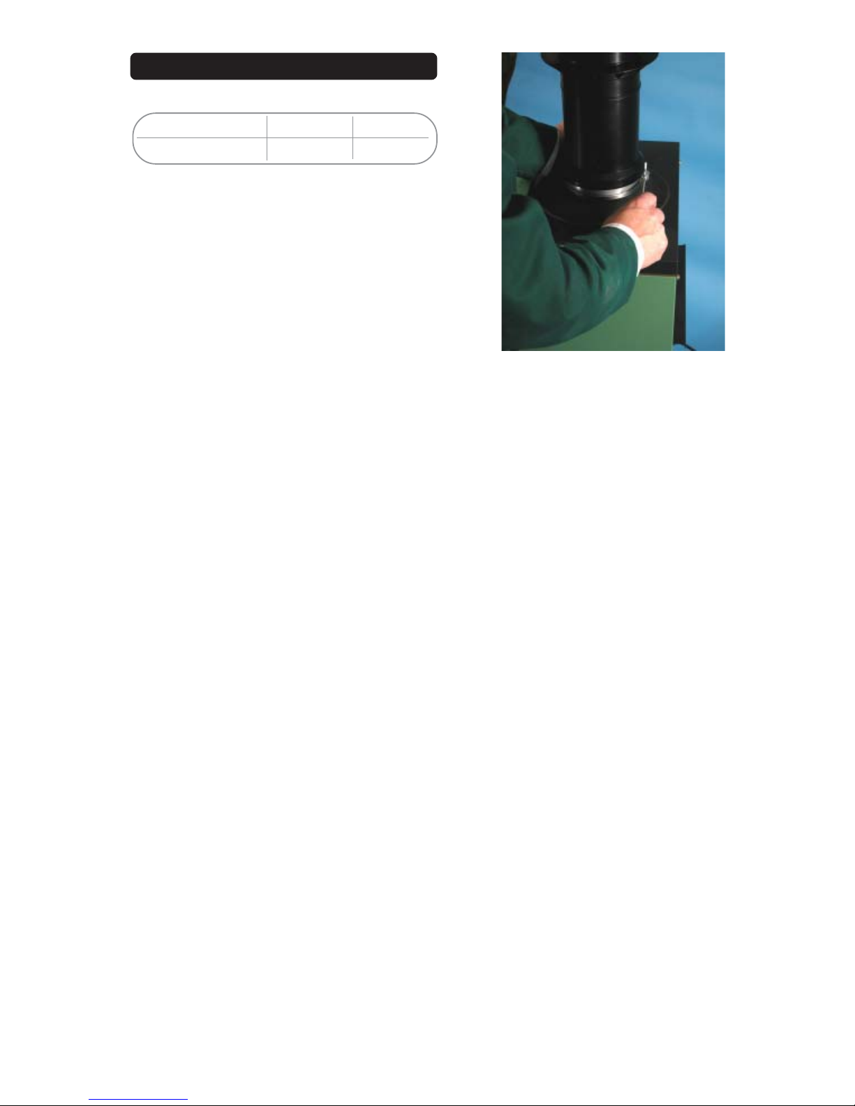
Assembly of the Outdoor Terminal
A specific Outdoor Top Terminal must be used for an
outdoor installation. There must be at least 600mm
clearance around the terminal and complete clearance above.
The Outdoor Top Terminal is a push fit into the Flue
Adapter and locked in position with a clamping ring.
(See Fig. 3.0 & 3.3)
If lubrication is required only Centra Cerin or silicone
grease should be used.
Condensing Pool Heater 6 22/12/08
All Other Flue Systems
The maximum Flue Equivalant Length (FEL)
permitted is 20 metres, horizontal or vertical. The
component parts have the following FELs:
1 metre of concentric flue 1.0
2 metres of concentric flue 2.0
A 45 degree concentric bend 1.1
A 90 degree concentric bend 1.5
A concentric Roof Terminal 3.3
A concentric Wall Terminal 3.9
Sum the Flue Equivalant Lengths used in the
design this must not exceed 20 metres.
Assembly
All items assemble by a push fit/clamp system. If it
is required to lubricate the seals only Centra Cerin
supplied by the manufacturer or Silicone Grease
should be used.
The pipes should be assembled so the socket end
is always furthest from the Heater.
Flues should be supported by brackets every
metre of run.
Horizontal flues should incline back to the Heater
by 3 degrees (5mm in 100mm)
Wall Terminal
The Horizontal Wall Terminal is supplied with two
rubber wallplates, one for inside and one for the
outside. The core drill diameter required is 175mm
and should incline upwards to the outside.
Because of the incline of the flue the height of the
centre of the flue hole on the inside will be determined by the distance the heater is from the wall.
the following is the suggeste procedure.
Fig. 3.0
Page 10
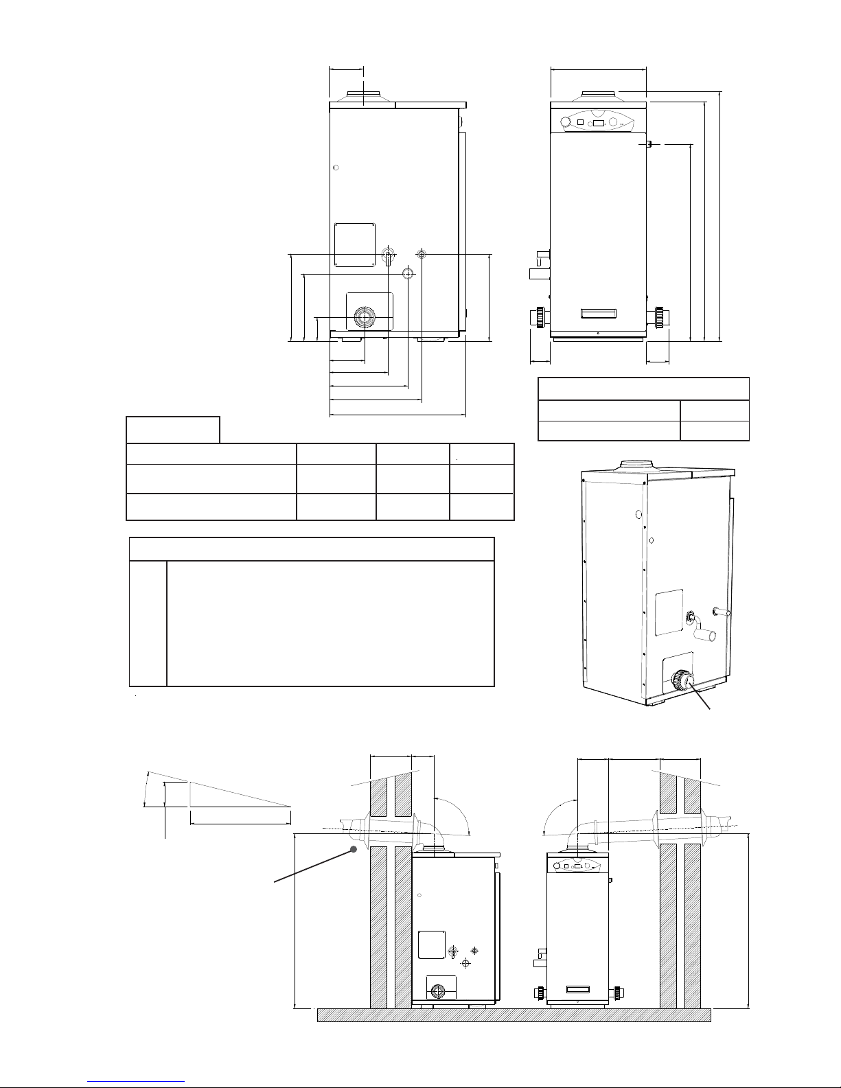
Heater Dimensions
Pipe Connections
& Locations
Condensing Pool Heater 7 22/12/08
Fig. 3.1
Dimensions
Model ABC
Genie 35 138mm 229mm 361mm
Genie 50 170mm 261mm 425mm
D
E
Connections
D Multi Heater Connection
E Electric & External Control (CCP01)
F Gas Supply - 22mm Copper
G Safety Valve Outlet - 15mm Copper
H Condensate Drain - 1¼” or 40mm Hunter Plastic
I From Pool - 1½” / 50 mm Plastic Demountable Fittings
Fig. 3.2
Service Access
Left, Right or Above 300mm
In Front 800mm
Rear Flue Left/Right Flue
Horizontal Wall Terminal
Dimensions
Horizontal Wall Terminal
(MBHT)
F
G
H
I
SW
WT
WT 136
188
9
3
°
9
3
°
1065
1065
52mm
1000mm
3
°
940
980
374
78
90
773
134
265
341
342
94
A
B
307
C
533
Page 11
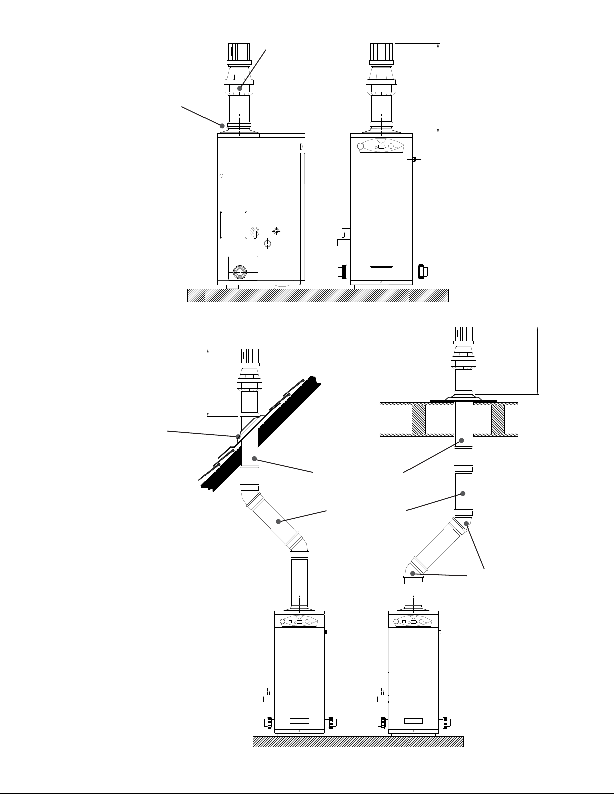
Outdoor Terminal
Dimensions
Condensing Pool Heater 8 22/12/08
Fig. 3.3
Outdoor Flue T erminal
(MBOT)
Fig. 3.4
Clamp Assembly Screw
Pitched Roof
Installation
Vertical Roof Terminal
Dimensions
Flat Roof
Installation
Use Seldeck Flashing
System for all Roof
Installations
Vertical Roof Terminal
(MBVT)
1 metre Horizontal/
Vertical Extension Pipe
(MBHVE)
45 degree bends
(MB45DB)
550
500
500
Page 12
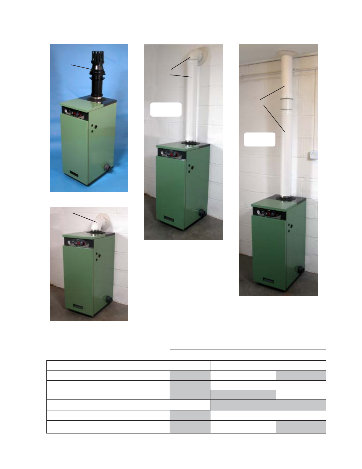
Condensing Pool Heater 9 22/12/08
Flue Examples
Flue Kit Part Codes
Type of Flue System
Kit Code Description Outdoor Kit Horizontal Terminal Vertical Terminal
MBHT Horizontal Wall Terminal n/a Yes n/a
MBHVE 1 metre Horizontal/V ertical Extension Pipe n/a Option Option
MBVT Vertical Roof Terminal n/a n/a Yes
MBOT Outdoor Terminal Yes n/a n/a
MB45DB 45 degree bend n/a Option Option
MB90DB 90 degree bend n/a Option n/a
Outdoor Terminal
Extended Horizontal
Wall Terminal
Extended Vertical
Roof Terminal
Horizontal Wall Terminal
MBOT
MB90DB
MBHVE
MBHT
(not shown)
TO OFFSET
USE MB45DB
MB90DB
MBHT
(not shown)
MBVT
MBHVE
TO OFFSET
USE MB45DB
Fig.4.3
Fig.4.0
Fig.4.1
Fig.4.2
Determine the type of Flue system you require and
choose from the list of kits available below:
Page 13
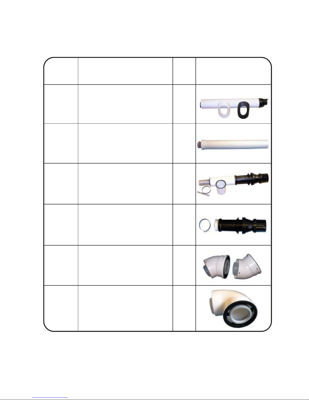
Condensing Pool Heater 10 22/12/08
Flue Kit Part Codes (cont.)
Kit Code Description FEL Photo of Kit
MBHT Horizontal Wall Terminal 3.9m
MBHVE 1 metre Horiz./Vertical Extension Pipe 1.0m
MBVT Vertical Roof Terminal 3.3m
MBOT Outdoor Terminal n/a
MB45DB 45 degree bends (pair) 1.1m
MB90DB 90 degree bend 1.5m
Flue
Equivalent
Length (m)
The Maximum Flue Equivalent Length (FEL) permitted is 20 metres, horizontal or vertical. The Flue Kits available below list the FEL for each component. Add up all the FEL’s used in your design and check that this does
not exceed 20 metres. (see page 6)
(per bend)
Page 14
Condensing Pool Heater 11 22/12/08
1. Ensure the required service clearance is
available.
2. Fit the 90 degree elbow to the heater and
measure from its outlet face to the wall.
3. Add 5 mm for every 100 mm distance to
1065 mm.
Example:
Distance measured = 480 mm
(5 x 480) / 100 = 25 mm
Flue centre 1065 + 25 = 1090mm
If it is required to reduce the length of the Terminal
the minimum overall length is 300mm. The Flue
duct should be cut 10mm longer than the Air duct.
Terminal Guard
The flue products from this appliance are very low
temperature so a guard is only required if the
terminal is is in a position where it may be damaged. A suitable guard is available from:
TFC Ltd. 01732 351555, Model DK6
Roof Terminal
The Vertical Roof Terminal should be fitted in a
minimum of 300mm clear unobstructed space. It is
not permitted to alter the construction of the Terminal, above the roof line, however the concentric
section below the roof line can be altered to suit
the installation.
It is recommended that:
1. The Installation of the flues are completed
before their connection to the Heater. This will
ensure that any debris that gets into the flues
can be cleared.
2. That bends in vertical flues are 45 degrees.
3. Flues may be reduced in length by cutting. The
inner Flue pipe should be cut so it is 5 to 10mm
longer than the outer Air duct. It will ease
assembly if the cut edges are cleaned, chamfered and greased before assembly.
Plumbing
The heater requires water flow and pressure to operate properly. It must therefore be installed downstream of the filter and pump. A typical installation is
plumbed as follows:
1. The Pump outlet is plumbed to the inlet of the Filter.
2. The outlet side of the Filter is then plumbed to the
inlet of the Heater.
3. The outlet of the Heater is plumbed to the return line
to the pool or spa. The Pump, Filter and Heater are
plumbed in series.
If it is necessary to install a valve on the return to the
Fig. 5.0
pool then it is recommended that a flow switch is
installed and interlocked with the Heater supply.
The Heater must be located so that any water leaks
will not damage the structure of adjacent area. There
is no requirement for heat shunt connections to the
Heater, plumbing can be made in standard plastic
1½” or 50mm pipe from the supplied demountables
Use the pressure loss chart on page 5 to specify a
suitable pump.
Connection to the Heater can be made from either
left to right, or right to left, it is supplied with the
‘From Pool’ connection on the left. To change,
undo the demount connection on the right, com-
plete with blanking plates, and swap with the
connections on the left. Ensure that the Pool
Sensor is correctly positioned in its pocket afetr
the change.
Flow Rate
The Heaters have a very low resistance to the
Pool Water flow and will tolerate a wide range of
flows.
The minimum recommended flow is:
80 litres/min
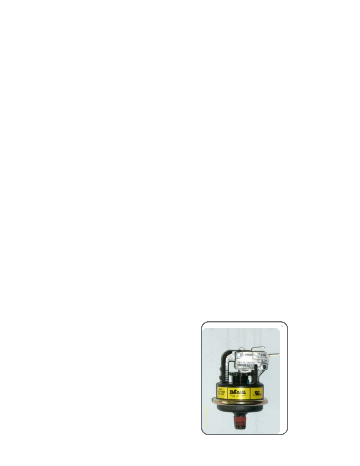
Pressure Switch
The Heater is protected by an adjustable water
pressure switch that has to close before the
Heater will operate.
It is very important to verify that it turns off
when the water flow is interrupted.
It has an adjustment range equivalant to ±1.5
metres. The switch is factory set for most conditions but can be altered if required:
1. With the pump on turn the knurled nut clockwise until a click is heard.
2. Turn the nut anti-clockwise a quarter of a turn.
3. Turn the pump on and off to check the switch
operates correctly.
Page 15
Conversion to LPG
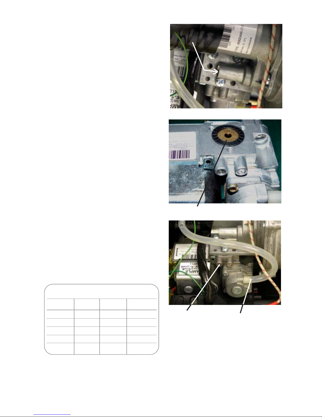
The Heater can be converted on site. NG to Propane, or Propane to Butane.
1. With the Gas and Electrical supply off, undo
the three screws that hold the Venturi to the
Gas Valve. (See Fig.6.0)
2. Allow the Gas valve to drop and gently hang
on its cables.
3. Fit the Conversion Orifice into the Rubber
Seal that sits in the Gas Valve. (See Fig.6.1)
4. Re-assemble the Gas Valve and Venturi.
5. Affix the new LPG Serial Number Data
Label supplied over the existing.
6. Turn Gas on and check for leaks.
7. Fire Heater and allow to run for 5 minutes
before checking and adjusting the CO2 with
the Throttle.
8. Replace the Sealing Cover over the Throttle.
(See Fig 6.0 and Datatable inside cover)
LPG to NG Conversion
The method is as detailed above except the Orifice
is removed and the Venturi and Gas Valve reassembled with just the Rubber Seal between them. A new
Serial Number Data Label should be obtained from
the manufacturer and affixed over the existing.
Gas Connection
The 22mm copper gas connection provided can be
positioned to exit the Heater from either the left or
the right. A minimum of 20mb. (NG), 37mb (propane)
28 mbar (butane) must be available at the Heater
inlet, with the Heater and other connected appliances firing. Check for gas tightness (B.S. 6891:
1988) in pipework to boiler using a manometer.(See
Fig. 6.2) Gas and combustion soundness within the
Heater should be checked using sense of smell and
leak detection fluid. Check the maximum rate and
combustion are to specification.
See Table 6.0 and Datatable Inside Cover.
Condensing Pool Heater 12 22/12/08
Rating Table (1040 Btu/ft³) (38.8 MJ/m³)
kW gross Btu/h sec/ft³m³/2 mins
7.5 25590 145 0.023
12.5 42650 87 0.039
20 68240 55 0.062
34.6 108055 31.5 0.107
52 177420 21 0.161
Table 6.0
Inlet pressure
tapping
Offset
connection
Fig. 6.0
Fig. 6.2
Throttle
Adjustment
Fig. 6.1
Orifice in position
Page 16

Condensing Pool Heater 13 22/12/08
Condensate Connection
The direction of the plastic condensate drain pipe
connection can be altered from the factory position
on the left, to the right.
Remove the blanking plate from the left hand
side (See Fig. 3.1)
Loosen the two screws holding the Trap
bracket and swivel the trap through 90 degrees.
Secure the bracket and fit the supplied 40 mm
pipe.
Example installations are shown in Fig 7.0.
Fit blanking plate to the right hand side.
(See Fig 7.1)
Where possible an internal termination of the condensate discharge pipework should be used.
If this is not possible external pipes should be kept
as short as possible and insulated.
Where fitted in pipework that includes another trap
or a pump, for example the filter backwash pipework
to drain, an Air Break should be fitted between the
Heater and that pipework.
Avoid connecting to a kitchen sink trap as the solids
and fats in the drain will cause a blockage.
It is permissible to connect to an external gully or
rain water hopper provided they connect to a combined system.
The condensate should not be run into a ‘grey water’
recycle system.
If the condensate pipe is connected to a stack it
should join not less than 450 mm above the foot of
the stack. In addition it should be positioned so there
no chance of cross-flow to another connection.
Installation pipework must be in 1¼” or 40 mm
Hunter plastic pipe to a suitable drain location with a
gradient of 2.5° (45mm/ metre run) minimum. If
connected to another drainage trap, an air break is
required between the Heater drain and that trap.
(See Fig.7.0 & 7.1). External runs, should, if possible, be insulated to defer problems from freezing.
Check during commissioning that there is a leak free
working connection from the Heater to the drain.
The simplest way to do this is to carefully pour some
water into the boiler flue and check it emerges at the
drain. This will also fill the trap ready for operation.
The “Guide to the Condensing Boiler Assesment
Procedure for Dwellings” can be refered to, see
http://www.planningportal.gov.uk/england/professionals/en/1115314255842.html
Electrical Connections
WARNING: The appliance MUST be earthed.
All wiring for the Heater and system controls MUST
conform to I.E.E. Wiring Regulations, and work
should be tested using a suitable meter, for Earth
Continuity, Polarity, Short Circuit and Resistance to
Earth.
The Heater supply must be through a common
isolator, a double pole 3A fused isolating switch with
a contact separation of 3mm minimum on both
poles.
The cable used should be no less than 0.75mm
2
to
BS.6500 PVC, 3 core, and fixed ensuring the earth
connection is longer than the Live and Neutral.
Access to the Heater connections is made by the
removal of the Front Top Panel and the Electrical
Chassis cover, two screws.
The simplest and most flexible control scheme is to
use a Certikin CCP01 Control Unit. This provides
an electrical safety trip and timer with outputs for
the Heater, lights and an auxilary voltage free
output. It is pre-wired and tested and provided in a
standard IP55 plastic control box.
The Heater’s internal wiring is shown in Fig.11.0.
Connections are as follows :-
4 Way Terminal Supply Connection
Earth
N Mains Neutral
SL Switched Live
L Permanent Live
A factory installed link has been fitted between SL
and L which should be removed if the Heater is to
have its own switched supply.
For systems using an external programmer, the
electrical wiring should follow the relevant control
manufacturer’s recommendations, with the
switched live from the controls returning to SL in the
4 way push-fit connector.
It is possible to connect several Heaters together
using the Multiple Heater Kit. Details for the parts
and installation of this kit are given on Page 17.
Page 17
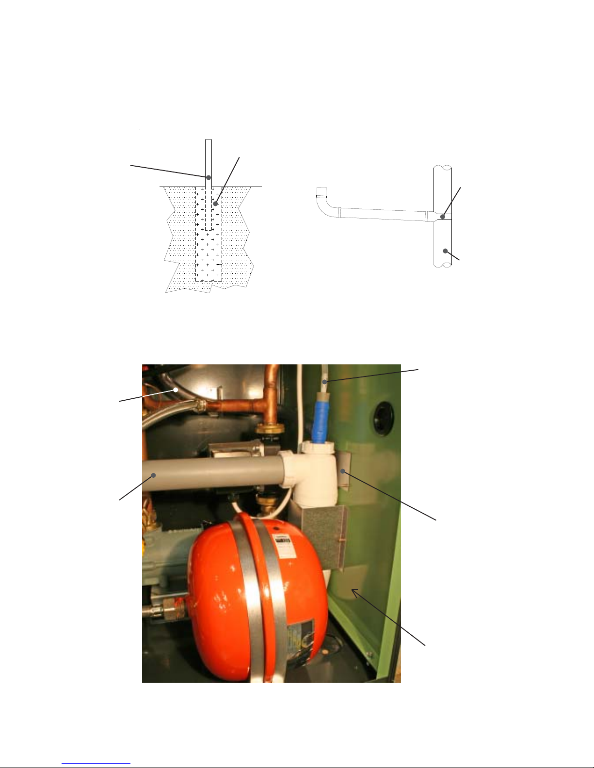
Example Condensate Disposal Methods
Condensate
Drain from
Heater
Condensate Pressure
Switch Pipe
Connection
Connect To
Waste
(Option to
exit Heater
left or right)
Drain Cap, (behind
vessel) can be
removed for
Winterisation
Condensate Syphon (75 mm)
Condensing Pool Heater 14 22/12/08
Fig.7.1
Removable Plate
(Use to close off
unused Waste exit
on panels)
1:20 Fall ( 2.5 Degrees )
Strap-On
Boss
200mm Land Drain
Filled with Lime
chippings 400mm
deep
Insulate against
freezing
Note: Do not reduce the pipe size below the 40mm provided.
Fig.7.0
Soakaway
Stack Att achment
Soil Pipe or
Drain
Page 18
Condensing Pool Heater 15 22/12/08
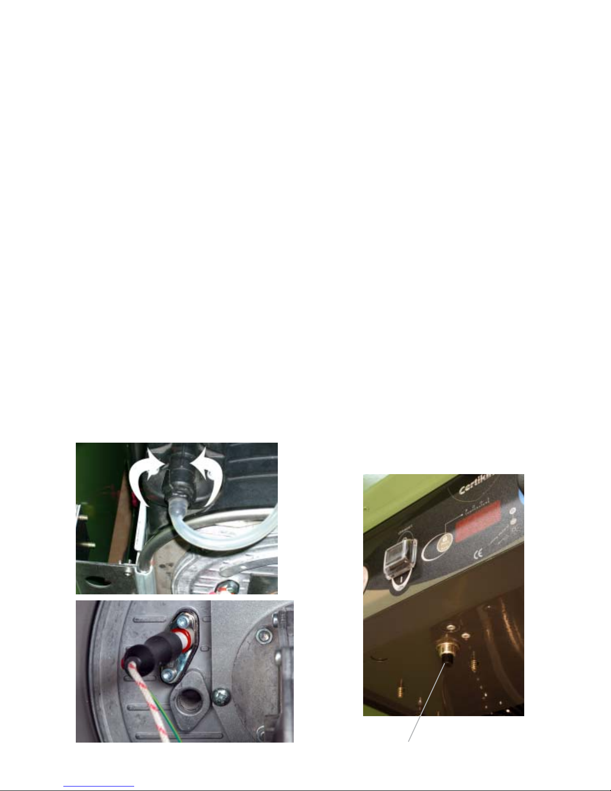
Fig. 8.2
Commissioning
General
IMPORTANT The heater primary contains Sentinel X500 inhibitor/anti-freeze. The minimum water
should be released during filling to maintain it s
concentration.
The elimination of air from the heat exchanger is
essential to maximise the life of the Heater.
It is strongly recommended that the Heater is first run
with the GAS OFF until the air has been purged.
If air has not been released then there is a possiblity
of the Heater overheating and triggering one of its
safety thermostats. An Air Vent is provided on the top
of the Heat Exchanger (See Fig 8.0) to assist its
removal. It is opened and closed by rotating the front
connector.
A second is a standard radiator vent in the righthand
Side Panel.
A button has been provided to just run the internal
pump (See Fig 8.1) to aid de-aerating. It requires that
the Mains in connected and on, the Pool Pump need
not be. See Page 6 for more details.
Commissioning Procedure
The Heater Control is factory set to display in Fahrenheit and work to a maximum temperature of 90°F
(32°C). If a Centigrade display or higher temperature
106°F (41°C) maximum is required, enter User Setup
Mode. (See Page 16)
The boiler is factory set for Natural Gas and fitted with
automatic ignition and will start when the gas cock is
open, mains is connected and the Pressure Switch is
activated by the pool Pump. (for greater detail about
the internal controls see the Maintenance section,
Fig. 8.0
Fault Diagnosis)
LPG models require to be modified as described on
page 12.
It is recommended that the condensate trap is full of
water before firing.
If the Heater fails to light the gas it will shutdown
and try again. It will repeat this a total of 5 times and
then locks out. This will show as the Red LED lit
and ‘GAS’ on the display. Press the Lock/Reset
button to start another 5 attempts.
It is possible with the front door off to see when the
burner is lit through the sight glass. (See Fig. 8.2)
After the burner has been lit for a few minutes the
gas rate and combustion should be checked, see
the Technical Data on Inside Cover for details.
The Heater is factory set and should not require
adjustment. When the Heater has been running for
at least 10 minutes check all joints, gas and water,
for leaks, and correct where necessary.
When running satisfactorily, complete the commissioning details on the inside back page of these
instructions.
Note: The boiler is fitted with a syphon trap that includes a blocked drain detection device. This is to safeguard the boiler from a blockage or the possible freezing of the condensate pipework in extreme weather.
Should this happen the control will lockout and the
display will show ‘HI’, as in “condensate level is high”.
See the Fault Finding section for more details.
This will have to be corrected before the Heater will
run.
The user should be made aware of this feature and,
that in the event of blocked or frozen condensate
pipework, the boiler will automatically stop functioning.
It will start again as soon as the blockage has cleared.
Finally , instruct the user on Heaters operation and controls.
Fig. 8.1
Button
Page 19
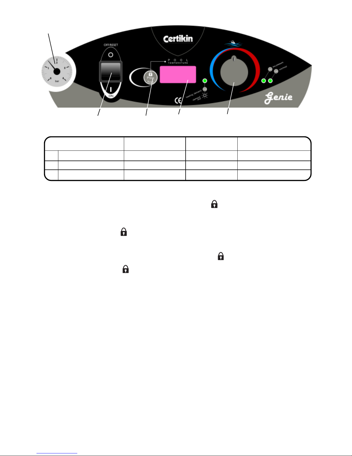
Condensing Pool Heater 16 22/12/08
User Setup Mode
Switch on with the panel switch whilst pressing the Lock/Reset button. then release. The control is now in
Setup Mode.
The control can now be altered by rotating the Pool Temperature Control Knob to a certain position and then
pressing the Lock/Reset button, then switching off. (See Fig. 9.0)
Example:
To change from Fahrenheit to Centigrade:
Turn Panel Switch OFF then back ON whilst pressing the Lock/Reset button.
Turn the Pool Temperature Control Knob until the display shows ‘F’.
Press the Lock/Reset button once and the display will show ‘C’.
Switch the Panel Switch OFF then back ON again.
The Control will now display in Centigrade.
Lock/Reset
Button
On / Off
Switch
Temperature
Display
Pool Temperature
Control Knob
Fig. 9.0
User Setup Mode Setting Factory Setting Alternative Display Indicator
1 Display units ° F = Fahrenheit ° C = Centigrade ° F or ° C
2 Maximum temperature 32 °C (90 °F) 41 °C ( 106 °F) PL or SPA
3 Software Version e.g 011
Pressure
Gauge
Page 20
Kit Part Codes:
2 Heaters: MBMIK2
3 Heaters: MBMIK3
4 Heaters: MBMIK4
5 Heaters: MBMIK5
6 Heaters: MBMIK6
7 Heaters: MBMIK7
8 Heaters: MBMIK8
Multiple Heater Kit
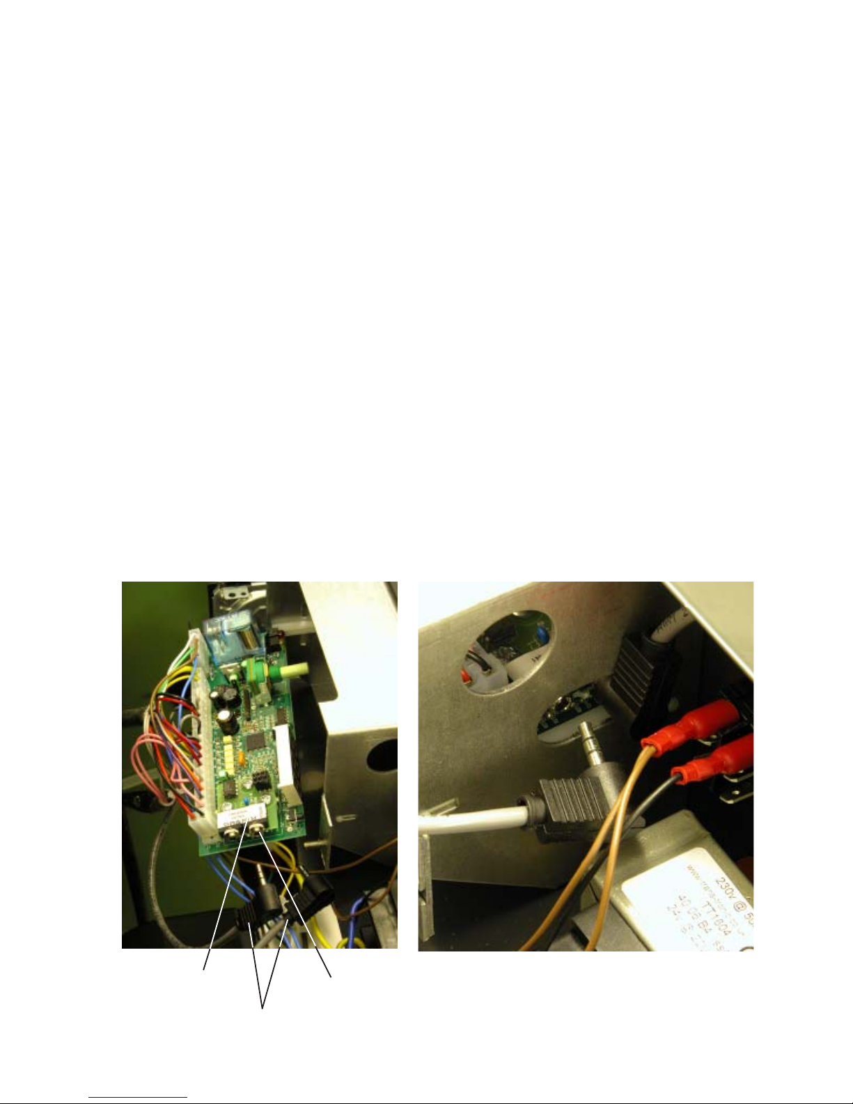
Adapter PCB
Connectors
Photo 2
Overview
It is possible to connect together several Heaters
and by doing so obtain a larger output with an
economical and a fail-safe design. The Multiple
Heater Kit enables 2 or more Heaters to be connected to obtain the necessary Load Sharing,
automatically. This works by one Heater being a
Master and the others being Slaves. The Master is
set for the required pool temperature and it then
controls as many of the Heaters as necessary to
obtain the temperature. It also equalises the running
time of every Heater so they all do the same amount
of work.
Condensing Pool Heater 17 22/12/08
Fig. 10.0
Installation Instructions
Disconnect the Heater from the Mains then
remove the Top Panel and the Electrical Chassis
Cover.
Remove Pool Thermostat Control Knob
Remove Pool Thermostat Board by removing
retaining plate and carefully slide out until fully
accessible. (Fig. 10.0)
Carefully fit the Adapter PCB in the space behind
the Pool Temp. Display on the Board (Fig. 10.0)
ensuring that the six pins on the Board pass
through the underside of the Adapter PCB
and, that the plastic locking pillars snap into
place. Refit Pool Thermostat Board and Knob.
Repeat steps 1) and 2) for all the Heaters.
Using the supplied cables, pass them through the
upper side panel grommet and daisy chain the
Heater Adapter PCBs together. The first and last
Heater in the ‘chain’ will use the Terminator Plugs
to fill their 2 unused sockets. There are 2 different
coloured Terminators, they can go in either the
first or last Heater. NB. Ensure the connectors
are fully home (Fig. 10.1)
Choose which Heater is to be the Master and
then make the rest Slaves by disconnecting their
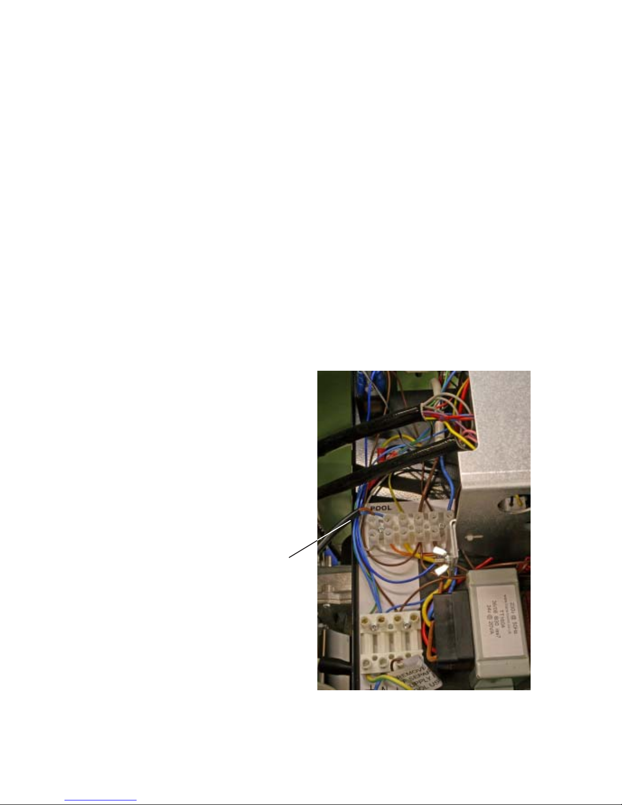
Pool Temp Sensors. Remove the leads to the
Pool Temp Sensor from the six way terminal strip
on the electrical chassis and tie back in a safe
place. (Fig. 10.2)
Any external electrical control should only be
connected to the Master, Pool Demand.
Remove any Pool Demand links from the Slaves.
Interconnection Cables
Fig. 10.1
Fig. 10.1
Page 21
Operation
Turn on all the Heaters with their Pool Tempera
ture Controls.
The Master will show temperatures and the Slaves
“---”.
Set the required temperature on the Master and
provided there is an electrical demand at the
Master’s Pool Demand connection, the Heaters
will run.
Features
A Master is the only Heater with a Pool Sensor
connected, move the sensor and the Master
changes.
If the Master Pool Temperature Control is
turned off, none of the Heaters will run.
If a Slave’s Pool Temperature Control is turned
off it will not operate. The Master will know and
alter its control accordingly.
If a safety device on the Master operates it will
not run but will continue to control the Slaves.
If the Master Control fails the ‘system’ will fail.
Change the Master to a Slave and one of the
Slaves to a master to enable the system to run
again.
If a safety device on any of the Slaves operates
that Slave will not operate.
Condensing Pool Heater 18 22/12/08
Turn on the Mains, then switch on all the
Heaters. After a short self-test the Mastershould
show the actual temperature, and the Slaves
three dashes “---”. If a Slave continues to show
a moving display of dashes this indicates it not
correctly connected to the Master, check the
Interconnection cable plugs are fully home.
Replace the panels.
Fig. 10.2
If a Slave has Flow fault which its Pressure
Switch detects the burner will stop immediately
and the Filter LED will light. It will no longer be
available to the group. It will then check every 3
minutes or so to see if the problem has been
corrected, the Filter LED will flash. It will put
itself back in the group if flow is satisfactory.
The Master display can be altered in Setup
Mode like a single Heater. (see Page 16)
Unlike a single Heater, there is no modulation
of individual burners.
Displays
The Master display is just like a single Heater.
A Slave will display “---” when working as part of
the group. It will show all the fault conditions of a
single Heater except “P/oc”, the Pool Sensor
Open Circuit fault. If this is displayed it indicates
a interconnection problem, check the cables and
connectors.
The Pool Demand LEDs work as a Single Heater.
On when running, Off when off, and Flashing if
not needed by the Master.
The warning LEDs work for all in a group, as per
a single Heater.
Pool Temp Sensor wires
Page 22
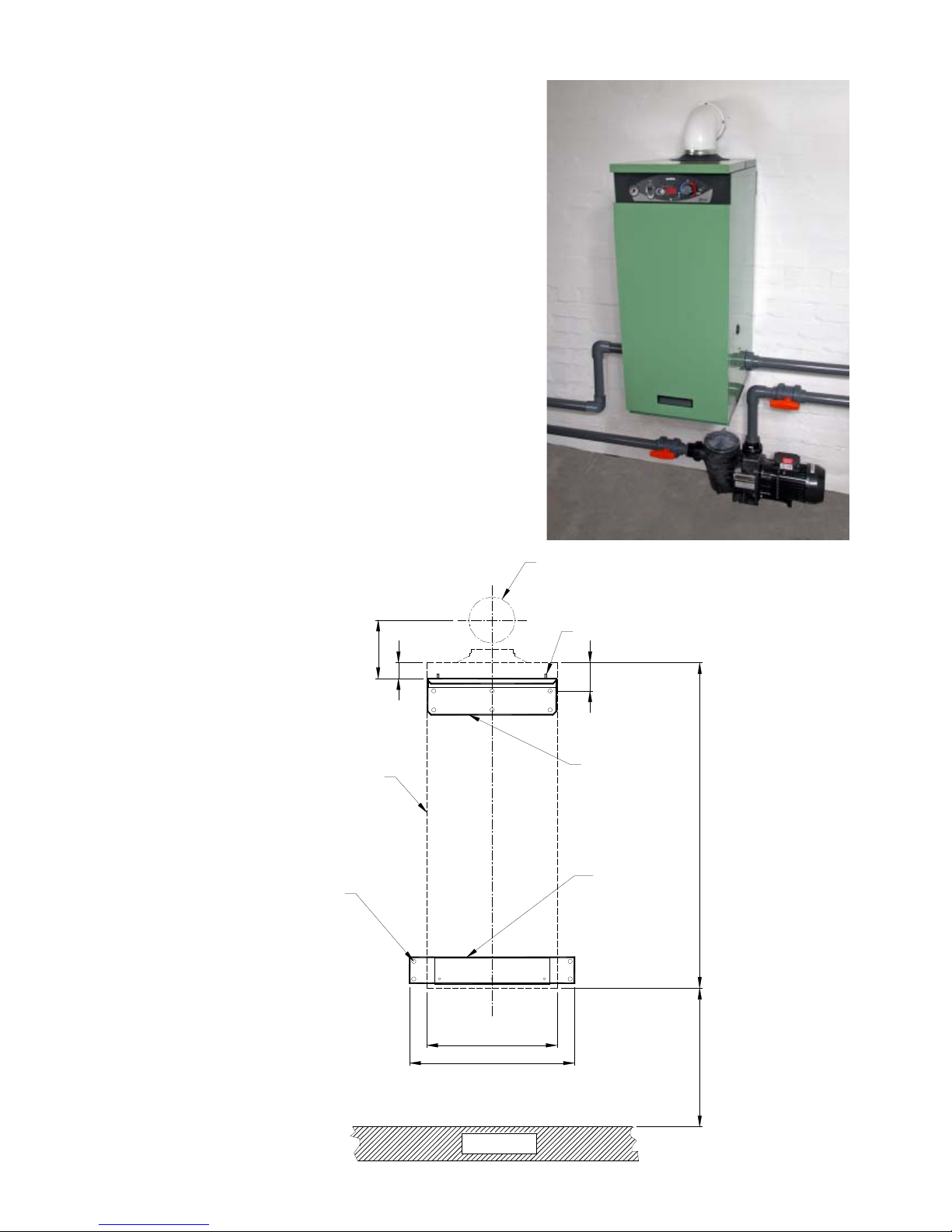
Wall Mounting Kit
Condensing Pool Heater 19 22/12/08
Fig. 10.4
Fig. 10.3
476
376
940
170
46
HEATER
OUTLINE
TOP WALL
MOUNTING
BRACKET
HORIZONTAL
WALL
TERMINAL
CORE DRILL
POSITION
BOTTOM WALL
MOUNTING
BRACKET (FITTED TO
HEATER BEFORE
WALL HUNG)
FLOOR
DRILL HOLES AFTER
HEATER HAS BEEN
WALL HUNG
5MM STUD (2 PLC'S)
HEATER CABINET HEIGHT
HEATER CABINET WIDTH
80
REQUIRED CLEARANCE
Overview
The Genie 35 and 50 models can be wall hung
using the Wall Mounting Kit.
Kit Part Code: MBWMK35/50
Instructions
Select a suitable wall and position to mount the
Heater. (Note the Heater weighs 40kg.)
Screw the Top Wall Mounting Bracket level to the
wall. (Fig 10.4)
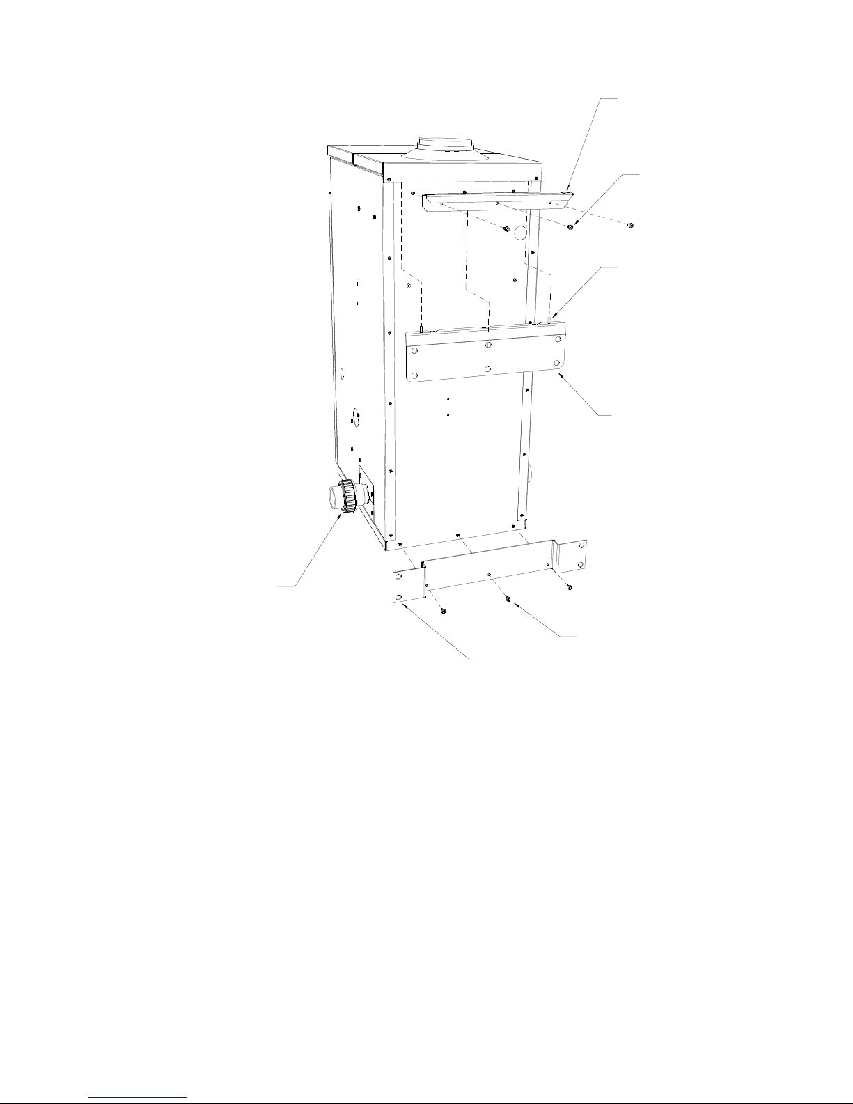
Attach the Top Handle Bracket to the rear of the
Heater by using the 3 M4 screws supplied.
(Fig 10.5)
Attach the Bottom Wall Mounting Bracket to the
rear of the Heater by using the existing 3 gold
screws that fix the base to rear panel.(Fig 10.5)
Hang the Heater on Top Wall Mounting Bracket
locating it on the two 5mm studs.
With the Heater now in position drill and screw
the Bottom Wall Mounting Bracket to the wall.See
(Fig 10.4)
Page 23
Condensing Pool Heater 20 22/12/08
Fig. 10.5
BOTTOM WALL MOUNTING BRAKET
REMOVE DEMOUNTABLE
POOL FITTINGS FOR BETTER
DRILL ACCESS
TOP WALL
MOUNTING BRACKET
LOCATING STUDS
(2 PLC'S)
GOLD SCREWS SUPPLIED (3 PLC'S)
M4 SCREWS
SUPPLIED (3 PLC'S)
TOP HANDLE BRACKET
Page 24
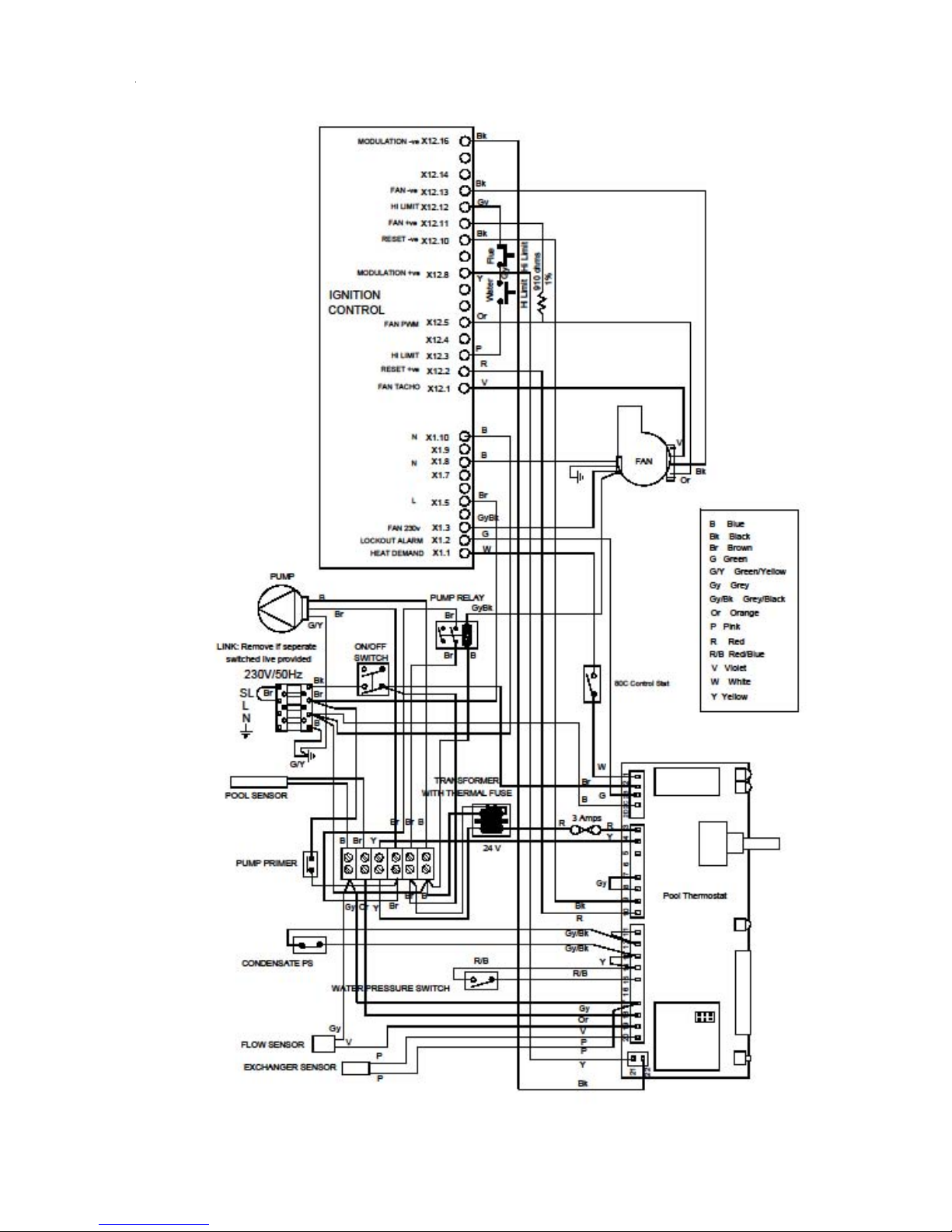
Fig.11.0
Condensing Pool Heater 21 22/12/08
Schematic Wiring
Page 25
WARNING: BEFORE COMMENCING OR COMPLETING ANY ELECTRICAL WORK ON THE APPLIANCE, IT
IS RECOMMENDED THA T THE BASIC SAFETY CHECKS FOR EARTH CONTINUITY, SHORT CIRCUIT, POLARITY AND RESISTANCE TO EARTH ARE MADE. ALL WORK CARRIED OUT SHOULD FOLLOW GUIDELINES LAID DOWN BY THE I.E.E.
Operation
The Heater requires Mains on both the Live (L) and Switched Live (SL) connection to be able to run. It is
delivered with a link between them which can be removed if a separate Heater switched live is going to be used.
To run, the Heater must have a Mains supply, Gas, Pool Pump pressure sufficient to activate the Pressure
Switch, all safety switches closed and a pool temperature below the set point.
If all the above are correct then the Gas Ignition Control starts the Ignition sequence:
1. The Fan and internal Pump runs as a pre-purge of the Heat Exchanger
2. After a few seconds a spark is created at the electrode and the burner is lit.
3. The burner flame is sensed and the spark is removed.
4. The Fan speed is then changed to the required speed according to the modulation curve.
5. If it fails to light the burner the spark will stop and the Fan and internal Pump will run on as a post-purge of
the Heat Exchanger.
6. The ignition sequence will be repeated up to five times, then the control will lockout and will require
a reset to start again.
Safety Controls & Lockouts
The Pool Thermostat Control indicates the actual and set temperature of the pool and also displays all the
lockouts. The next pages detail the fault conditions, the indicators, the display and the actions required.
User Setup Mode
Turn off on the Panel Switch. Turn on with the Panel Switch whilst pressing the Lock/Reset Button.
The Control is now in User Setup Mode. See Page 16 for details.
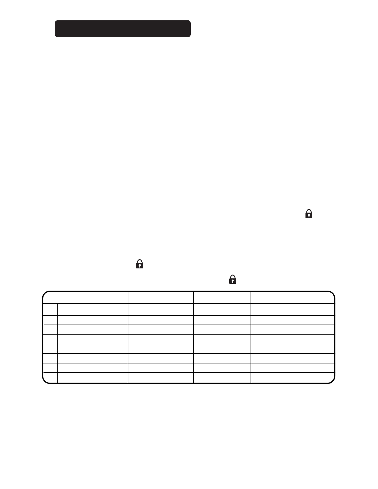
Service Mode
This is a special mode used to set the operation of the Control and to investigate fault conditions, it is entered
from User Setup Mode.
Rotate Pool Thermostat knob fully clockwise to show the software version number.
Press the Lock/Reset Button for 3 seconds. The control is now in Service Mode.
It is now possible to change some of the Control’s parameters. To show them, rotate the Pool Thermostat
Potentiometer. To zero or change them, press the Reset/Lock button
To exit, turn the Panel Switch off then back on again.
Condensing Pool Heater 22 27/02/09
Test Temperature Display Mode 1 (td1).
Temperatures are displayed to 0.1 degree resolution, not the normal 1 degree.
The display will now show each sensor temperature and cycle around them for each press of the Lock/Reset button.
1. Pool Temperature as normally displayed. The Green LED will be alight.
2. Pool Temperature is dispayed to 0.1 degrees. The Green LED will be alight.
3. Heat Exchanger Flow Temperature. The Yellow LED will flash rapidly.
4. Heat Exchanger Combustion Temperature. The Red LED will flash rapidly.
Rotating the potentiometer will change the set temperature. Pressing and holding the button whilst one of the
temperatures is displayed will ‘lock/unlock’ it on the display for continuous observation.
FAULT FINDING
Service Mode Setting Factory Setting Reset press Display Indicator
1 Pressure Log Number of Operations Resets to zero Yellow LED ON
2 Unused Red LED ON
3 Combustion Gas Log Number of Operations Resets to zero OH2, Red LED flashing
4 Gas Lockout Log Number of Operations Resets to zero GAS, Red & Yellow LED ON
5 Condensate Blocked Log Number of Operations Resets to zero HI, Front Red PCB LED ON
6 Unused Rear Red PCB LED ON
7 Hours run 0 Press resets to zero
156 =1560 hrs both PCB LEDs on
8 Display td0 td1 td0 / td1
Page 26
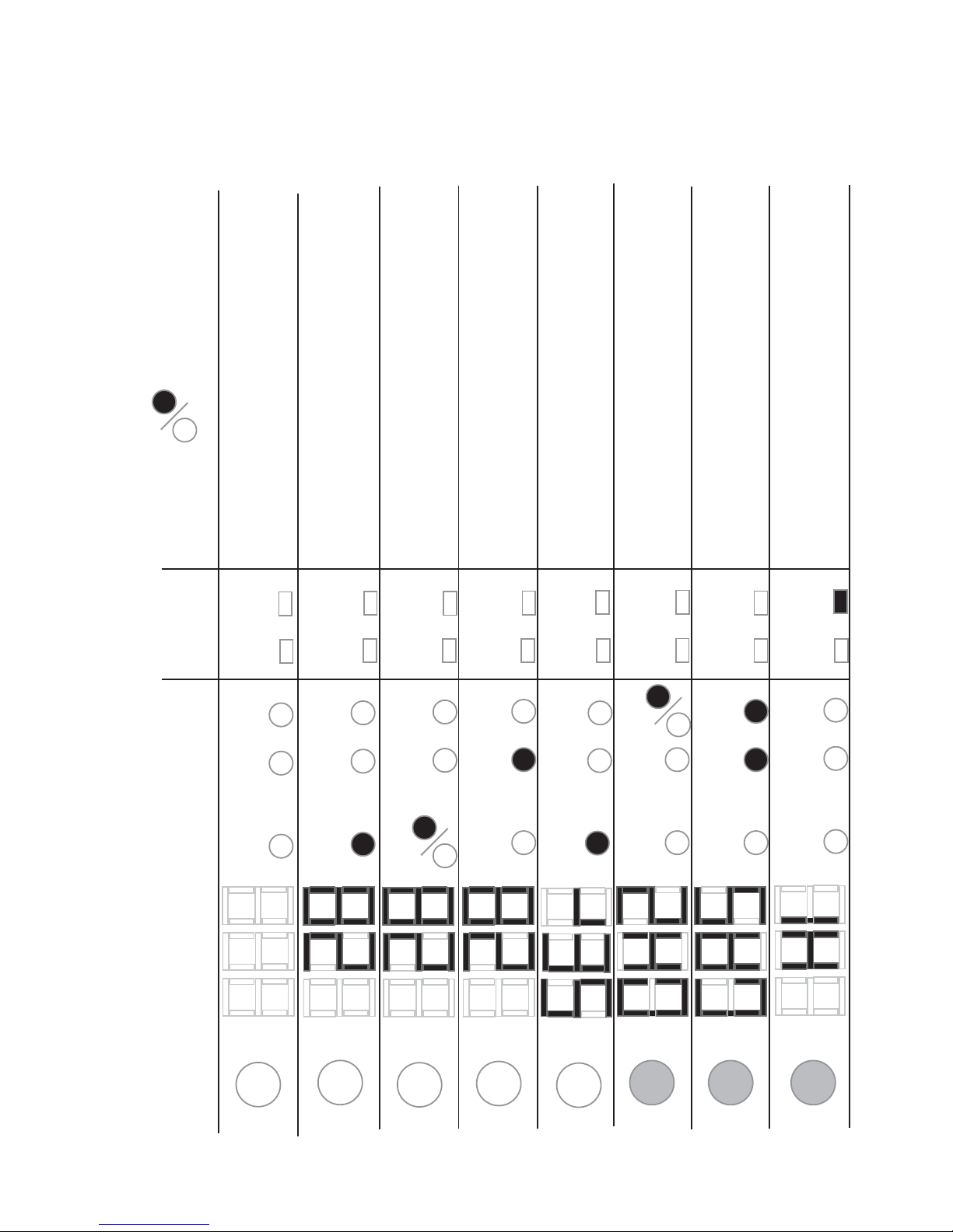
Fault Codes
Condensing Pool Heater 23 22/12/08
DISPLAY
LOCK / RESET
GREEN
YELLOW
RED
LED1
RED
RED
LED2
Running, raising pool temperature to 28°C
Up to temperature, 28°C
Insufficient water pressure. Filter?, Blockage?
‘OH2’ Flue gas over temperature. Allow to
cool then investigate in Engineering Mode.
Reset with Button
‘GAS’ Gas Control Lockout. Unable to light
burner, reset with Button. OR Flue Stat tripped.
Investigate cause. Reset on Flue Stat
FRONT PANEL
ON PCB
EXPLANATION
OFF, no mains supply or failed power supply
Flashing
‘HI’ Condensate level high. Blocked? Clear
obstruction and allow control to auto reset .
‘SEr’ alternating with pool temperature. Serv-
ice required, working hours has reached
setpoint.
Page 27
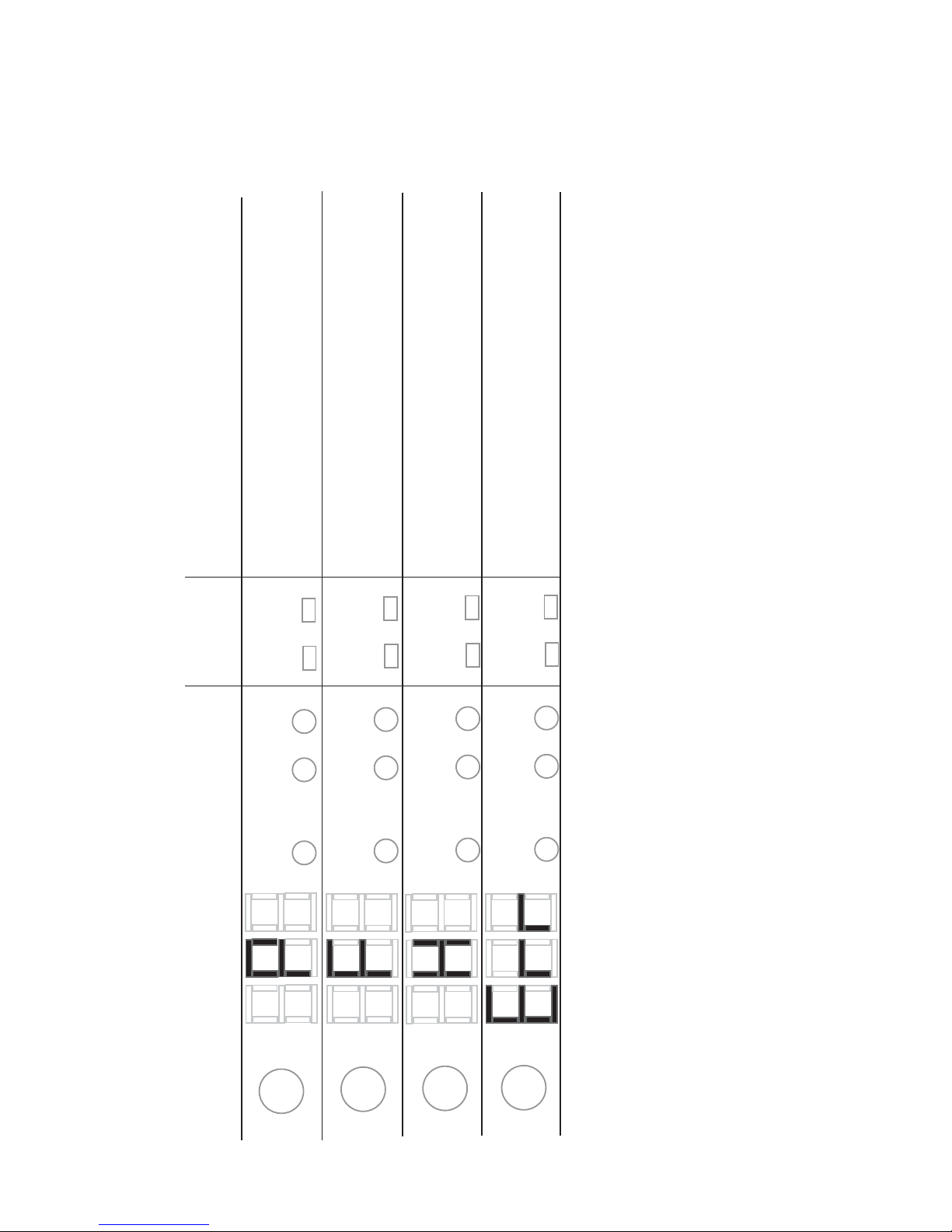
Fault Codes
Condensing Pool Heater 24 22/12/08
DISPLAY
LOCK / RESET
GREEN
YELLOW
RED
LED1
RED
RED
LED2
FRONT PANEL
ON PCB
EXPLANATION
‘P’ alternating with ‘oc’ = Pool sensor open circuit OR No
network detected if a Master in a multiple heater installation
‘P’ alternating with ‘cc’ = Pool sensor short circuit
‘F’ alternating with ‘oc’ = Heat Exchanger
Flow sensor open circuit
‘H’ alternating with ‘oc’ = Heat Exchanger
Combustion sensor open circuit
‘H’ alternating with ‘cc’ = Heat Exchanger
Combustion sensor short circuit
‘F’ alternating with ‘cc’ = Heat Exchanger
Flow sensor short circuit
‘Err’ alternating with ‘4’ = Pool potentiometer open circuit
‘Err’ alternating with ‘5’ = Pool potentiometer short circuit
For all of the above. Turn of f, correct problem and turn back
on again and the display and operation will be normal.
Page 28
SERVICING
Health and Safety Statement :
This Heater contains no asbestos.
Routine Service
To ensure continued efficient operation of the
appliance it is recommended that it is checked and
serviced at regular intervals.
The frequency of servicing will depend upon the
particular installation and usage but in general every
2000 hours of operation should be the maximum.
It is law that any service work should be carried out
by Corgi registered personnel.
1. Clean burner and combustion chamber.
2. Check condition of ignition spark and sensing
probe.
3. Check boiler pipework joints for leaks.
4. Check the Air duct and Flue seals.
5. Check condensate syphon and pipework for leaks.
6. Check the Gas Rate.
7. Check the combustion CO and CO2.
8. Reset the Service Hours counter in the control.
Follow the procedures given in Changing Components
for parts removal in addition to the following notes.
In all cases, before work commences turn off the
Mains Electrictity and Gas Supply.
Burner & Combustion Chamber
To view the burner and the inside of the Heat
Exchanger it is suggested you remove the front of
the Heat Exchanger complete with the Fan and Gas
Valve:
Remove Door and Front Top Panel
Disconnect Gascock flange form Valve.
Unplug Fan electrical connectors.
Remove Air tube from Flue Adapter.
Undo cover over Ignition Control connections
and remove the two connectors.
Pull off the Earth Lead connection on the
Valve and Heat Exchanger.
Undo the four nuts holding the Heat Exchanger
front and withdraw.
Assembly is the reverse.
Reset the Service Hours Counter. (See Service
Mode, page 22)
Spark & Sense Electrode
Turn off the Heater.
Pull off the HT Lead.
Undo the two screws retaining the electrode
assembly and carefully withdraw.
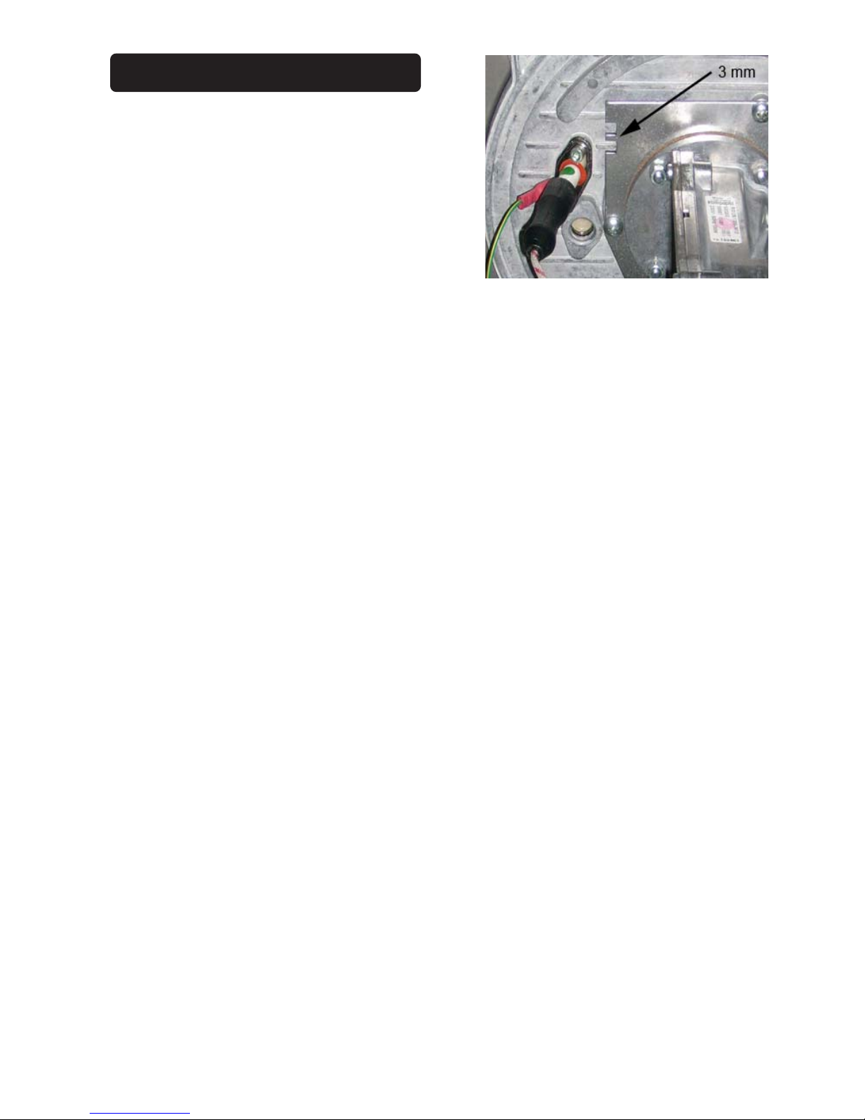
The spark gap should be 3.0 mm ± 0.5.
(See Fig 12.0)
Assembly is the reverse, ensure the gasket
is correctly placed.
Pipework
IMPORT ANT. The Heat Exchanger connections
are made using O rings and should not be strained
in any direction. Any strain will result in damage to
the Heat Exchanger and will not be covered by the
warranty.
All plastic pipework joints are solvent welded and
cannot be remade but have to be replaced.
Condensate Syphon
The lower bowl of the Syphon can be unscrewed,
examined and cleaned.
Air Duct & Flue Seals
A visual inspection should establish there are no
leaks around any of the seals, including the flexible
Air Duct to the Venturi.
Gas Rate & Combustion
See the Datatable on Page 1 for the correct values.
A Combustion sample point is provided on the front
of the Flue Adapter. (See Fig.14.1)
Changing Components
THERE IS ONE FUSE, THE REMAINDER OF
THE CONTROLS ARE NOT REPAIRABLE AND
IF NOT WORKING MUST BE REPLACED.
In all cases, before work commences turn off the
Mains Electricity and Gas Supply.
The following items can be replaced:
Fuse, 24V supply.
Transformer.
Pool Thermostat.
Condensate Pressure Switch.
Relay.
Pool Temperature Sensor.
Heat Exchanger Flow Sensor.
Water Pressure Switch.
Control Thermostat.
Overheat Thermostat.
Condensing Pool Heater 25 22/12/08
Fig 12.0
Page 29

Heat Exchanger Combustion Temperature Sensor.
Flue Thermostat
Ignition Control.
Gas Valve.
Fan.
Pump.
Heat Exchanger.
Secondary Heat Exchanger.
On the Electrical Chassis
To access these items first remove the Front Top
Panel and then the Chassis Cover.
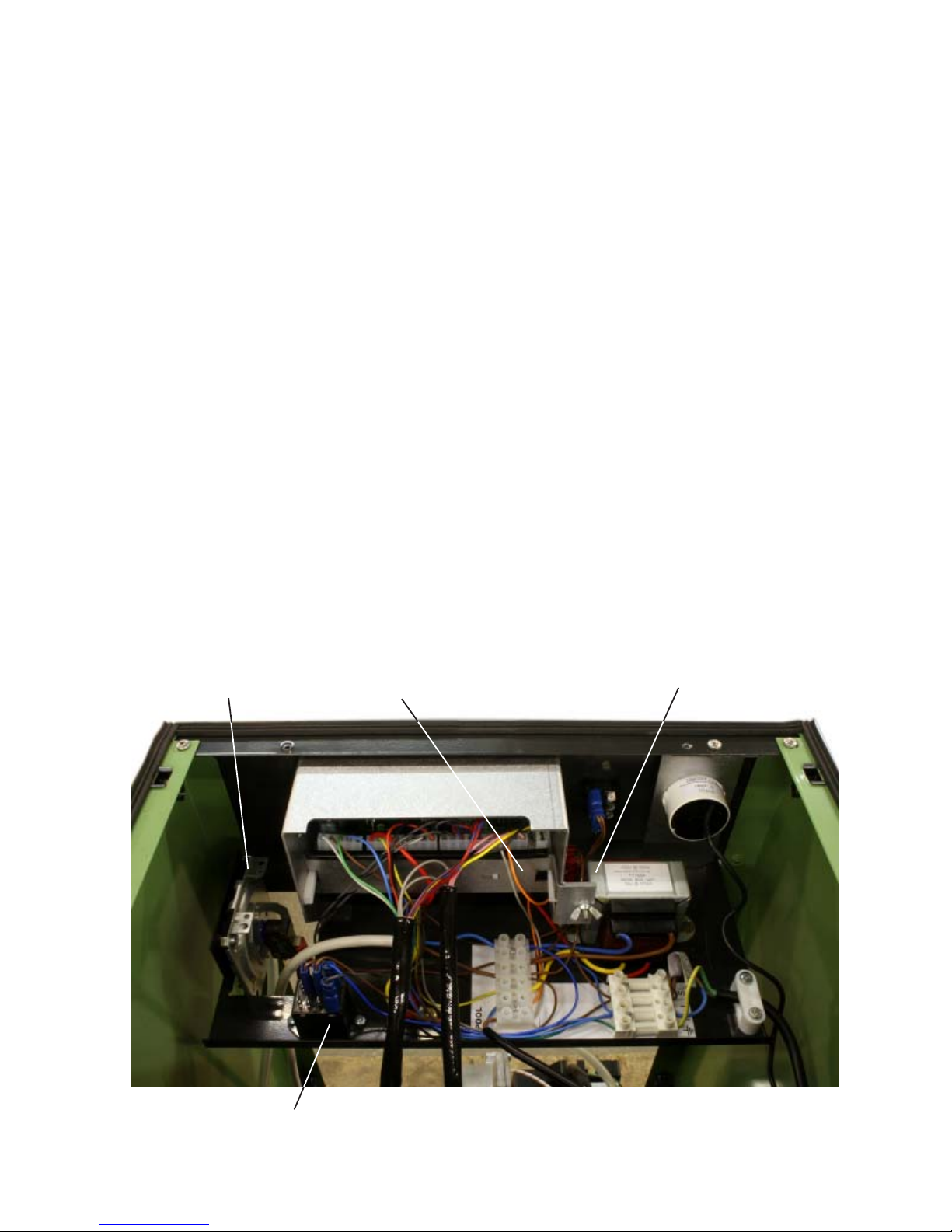
Fuse (See Fig. 13.0)
There is one inline 3A fuse on the 24V supply between the Transformer and the Pool Thermostat. The
Fuse Holder bayonets apart to allow its replacement.
Transformer (See Fig. 13.0)
The Transformer includes its own, internal thermal
fuse on the primary. If this has gone open circuit the
cause should be established before replacing the
Transformer.
Disconnect from the terminal strip and fuse
holder.
Undo the two screws holding it to the chassis and
replace.
Pool Thermostat (See Fig. 13.0)
Pull off the Pool Thermostat Knob.
Release the Rear Retainer by undoing the Wing
Nut.
Pull off all the PCB connectors.
Slide out the Thermostat.
Replacement is the reverse.
Condensate Pressure Switch
(See Fig. 13.0)
Undo the single fixing screw.
Pull off the two electrical connectors and transfer
to the new Switch. They connect to the ‘C’ and
‘NO’ connections.
Replacement is the reverse
Relay
(See Fig. 13.0)
Pull off the three electrical connectors and
transfer to the new Relay.
Undo the two fixing nuts and secure new relay in
position.
Heater Components
The remainder of the parts can be accessed
through the front.
Heat Exchanger Flow Sensor
This is located on the front connection to the Heat
Exchanger. (See Fig.14.4)
Condensing Pool Heater 26 22/12/08
Unclip the sensor from the connection.
Transfer the push on electrical connectors to the
replacement and clip back on.
Heat Exchanger Pool Sensor
This is located in a pocket in the ‘From Pool’ side of
the Secondary Heat Exchanger. (See Fig.14.6)
Pull out the retaining slipper, and pull out sensor.
Diisconnect from the six way terminal strip on the
Electrical Chassis.
Replacement is the reverse.
Water Pressure Switch
This is located on the Inlet connection to the Secondary Heat Exchanger and its removal will require the
draining or isolation of the Pool water in the Heater.
(See Fig.14.6)
Pull off the Electrical Connectors
Unscrew from the Secondary Heat Exchanger.
Replacement is the reverse.
If the Water Pressure Switch needs adjustment See
Page 12 for details.
Control Thermostat
This is located on the Outlet connection of the Heat
Exchanger. (See Fig.14.4)
Unclip the sensor from the connection.
Transfer the push on electrical connectors to the
replacement and clip back on.
Heat Exchanger Combustion
Temperature Sensor
This is located on the top of the Heat Exchanger, on
the right hand side. (See Fig.14.1)
Release the electrical connector by pressing the
latch and pulling up.
Twist the Sensor a quarter turn clockwise and
withdraw.
IMPORT ANT Ensure the O ring seal is fitted correctly
to the replacement before fitting.
Replacement is the reverse.
Flue Thermostat (manual reset)
This is located on the Flue Adapter. (See Fig.14.1).
Pull off the electrical connectors.
Slide out from under the clip.
Replacement is the reverse.
Ignition Control (See Fig.14.3)
Undo the single screw holding the Ignition Control.
Release the two electrical connectors by pressing
the latch and pulling apart.
Pull the Ignition Control away from the Gas Valve.
Replacement is the reverse.
Page 30

Condensing Pool Heater 27 22/12/08
Gas Valve (See Fig.14.3)
Remove the Ignition Control, see above.
Release the Gascock by undoing the four shoul
der bolts holding it to the Gas Valve.
Remove the Offset tube from the Gas Valve and
unscrew the Offset Connector and transfer to the
new Gas Valve.
Release the Gas Valve from the Venturi by
undoing three screws. (See Fig.14.3)
IMPORT ANT Ensure the rubber seal (and orifice if
Propane) is transfered from the old Valve and placed
between the Venturi and Gas Valve before assembly.
Replacement is the reverse.
Fire the Heater and check for gas leaks.
After five minutes check the rate and combustion
is correct to the Datatable. (inside cover). Adjust
using the throttle on the Gas Valve, (See Fig. 14.3).
Fan (See Fig.14.2)
Remove the two electrical connectors on the Fan.
Remove the two screws holding the Venturi to the
Fan.
Undo the four nuts holding the Fan to the Heat
Exchanger and withdraw. (See Fig.14.2)
Transfer the Venturi gasket to the new fan.
Replacement is the reverse.
Venturi (See Fig.14.2)
Remove the Ignition Control and Gas Valve, see
above.
Pull off the Air Tube (See Fig.14.3)
Undo the two screws holding the Venturi to the
Fan and remove.
Ensure the gasket is transferred to the new
venturi or positioned on the Fan before position
ing the replacement.
Replacement is the reverse.
Fire the Heater and check for gas leaks.
After five minutes check the rate and combustion
is correct to the Datatable. (inside cover). Adjust
using the throttle on the Gas Valve if required.
(See Fig.14.3).
IMPORTANT. The following components require the
draining of the primary . It is recommended that it is
re-filled with one litre Sentinel X500 Inhibitor/Antifreeze to provide winter protection. It is essential
that all the air is removed from the Heat Exchanger
before the Heater is fired. Running the Heater with
air still in it will damage the Heat Exchanger and
invalidate the warranty.
Pump (See Fig.14.0)
Drain the primary waterside of the Heater.
Diconnect the Pump mains lead from the six way
connector in the Electrical Chassis.
Undo the two water connections of the pump and
remove.
Transfer the mains lead to the new Pump.
Replacement is the reverse.
Heat Exchanger (See Fig.14.0)
The removal of the Heat Exchanger will require
the draining of the Heater.
Undo both the Demountable connections to the
Pool pipework. (See Fig.14.5)
Undo the screws holding the panels around the
Demountable connections. (See Fig.14.5)
Lower the pipework away from the Heat Ex-
changer.
Remove the Front Top Panel and disconnect
the Flue Thermostat connections.
Pull the Air Duct and Flue up and away from
the
Heater Flue Adapter.
Disconnect the Heat Exchanger Combustion
Sensor by pressing the latch and pulling off.
Remove the four screws holding the Rear Top
Panel.
Lift the Rear Top Panel with the Flue
Adapter clear of the Heat Exchanger.
Remove the Fan, Gas Valve and Ignition
Controller.
The Heat Exchanger is now only retained by
the two side brackets and releasing the four
front screws will enable it to be pulled forward.
Before releasing ensure there is support
available.
Replacement is the reverse.
IMPORT ANT: If the unit is fitted outdoors it
is recommended that it is re-filled with a
suitable anti-freeze, the manufacturer
recommends Sentinal X500.
Secondary Heat Exchanger (See Fig.14.0)
Drain the pool side sufficiently so that the
Heaters Pool Connections can be released.
Remove the Case retaining Plates around the
Heater’s Pool Connections.
Drain the primary system with the draincock
provided. Ensure an air vent is open to fully
release the water.
Remove the Pool Sensor from the Secondary
Heat Exchanger.
Remove the Expansion Vessel.
Remove the single screw fixing the Secondary
Heat Exchanger to its mounting plate.
Remove the single fixing screw holding the
Spacer below the Mounting Plate.
Pull out forwards the Spacer and remove.
Undo the primary Compression connections on
the Secondary Heat Exchanger and allow it to
drop off its connections and remove.
Replacement is the reverse.
IMPORT ANT: If the unit is fitted outdoors it
is recommended that it is filled with a
suitable anti-freeze, the manufacturer
recommends Sentinal X500.
Page 31
Spares
Item Mfg’ Part Number Supplier Part No
Primary Heat Exchanger (Genie35) M2136 SPMBG001
Primary Heat Exchanger (Genie 50) M2139 SPMBG002
Secondary Heat Exchanger M2678 SPMBG053
Propane Orifice (Genie 35) M2150 SPMBG014
Propane Orifice (Genie 50) M2151 SPMBG015
Fan M2138 SPMBG003
Gas Valve M2140 SPMBG004
Ignition Control M2141 SPMBG005
Pool Thermostat PCB M2155 SPMBG057
Relay M2688 SPMBG054
Pressure Gauge M4240 SPCOH2/003
Water Pressure Switch 650634 SPMB506
HT Lead M2142 SPMBG006
Condensate Syphon M2143 SPMBG007
Condensate Pressure Switch M2144 SPMBG008
Spark & Sense Electrode M2146 SPMBG010
Flue Thermostat M2147 SPMBG011
Control Thermostat M2667 SPMBG055
Pool Temperature Sensor M4416 SPCOH2/002
Ht Exchanger Flow Sensor M2149 SPMBG013
Genie Pump M2683 SPMBG056
Fig. 13.0
Pool Thermostat
Retainer
Transformer
Condensate
Pressure Switch
Condensing Pool Heater 28 22/12/08
Electrical Components
Relay
Page 32
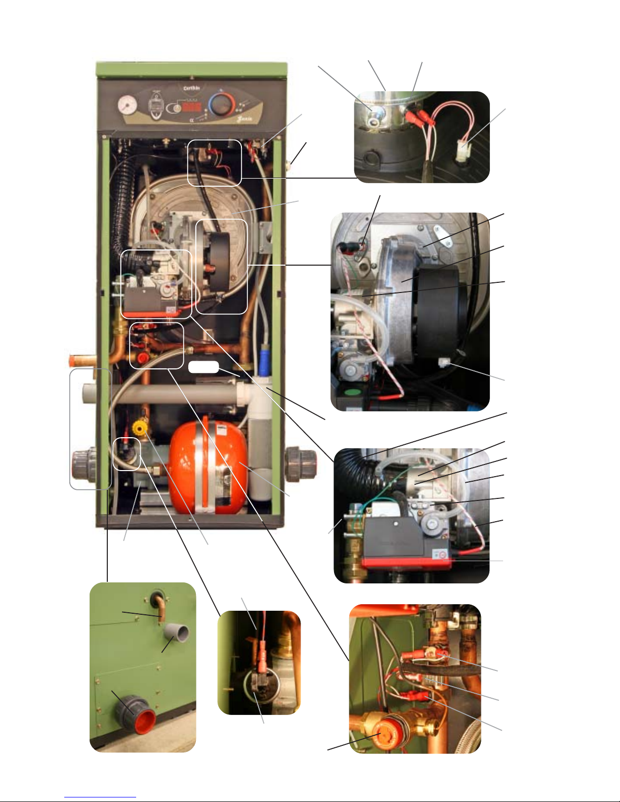
Fig.14.6
Heater Components
Condensing Pool Heater 29 22/12/08
Fig.14.0
Fig.14.1
Fig.14.4
Fig.14.3
Fig.14.2
Flue Thermostat
Heat Exchanger
Combustion
Temp Sensor
Fan Electrical
Connectors
Fan
Venturi
Fan
Fixing
Nuts
Ignition
Control
Gas Cock
Shoulder
Bolts
Offset
Tube
Venturi
Heat Exchanger
Flow Sensor
Heat
Exchanger
Control
Thermostat
Demountable Pool
Connections
Fig.14.5
Condensate
Pressure
Switch
Flue Adapter
Gas Valve
HT Lead
Spark & Sense
Electrode
Condensate
Syphon
Combustion
Sample Point
Air Tube
Throttle
Hi-Limit
Thermostat
Condensate Pipe
Safety Valve
Outlet
Expansion
Vessel
Secondary
Heat
Exchanger
Drain & Fill point
with NR & Isolation
valve
Safety Valve
Pool
sensor
Water Pressure
Switch
Pump
Air Vent
Page 33

Condensing Pool Heater 30 22/12/08
This page has been intentionally left blank
Page 34

Condensing Pool Heater 31 22/12/08
This page has been intentionally left blank
Page 35
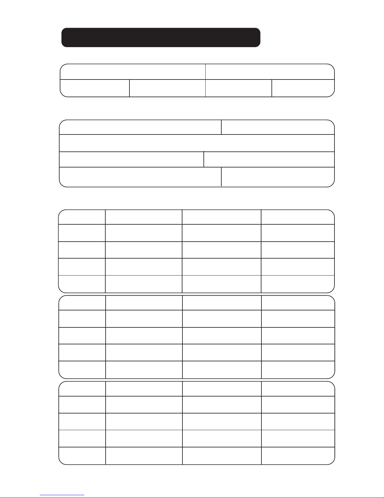
INSTALLATION & SERVICE HISTORY
Model Gas
Genie 35 Genie 50 NG LPG
Date
Cleaned ?
Pressure
CO
CO2
Service History
Commissioning
Installer Corgi No Date:
Working pressure mbar
CO ppm CO2%
Instructed User in operation? Yes/No
Tick appropriate:
Date
Cleaned ?
Pressure
CO
CO2
Date
Cleaned ?
Pressure
CO
CO2
Condensing Pool Heater 22/12/08
Page 36

Station Lane
Industrial Estate
Witney
Oxon.
Tel. 01993 778855
Fax. 01993 703407
22/12/08
 Loading...