

Page 1
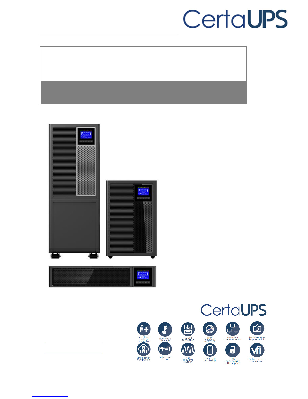
C500/C500R G2
Tower 6-10K
RT 6-10K
Installation/Manual
Page 2
SAFETY INSTRUCTIONS
SAVE THESE INSTRUCTIONS. This manual contains important information that
should be followed during the installation and maintenance of the UPS,
batteries and battery cabinet.
The C500® G2 models covered in this manual are intended for installation in an
environment between below 0 to 50°C, free of conductive contaminants and less
than 1000m altitude.
Certification standards
•
Safety: IEC/EN 62040-1
•
EMC: IEC/EN 62040-2
•
Performance: IEC/EN 62040-3
•
IEC 61000-4-2 (ESD): level 4.
•
IEC 61000-4-3 (RS): level 3.
•
IEC 61000-4-4 (EFT): level 4.
•
IEC 61000-4-5 (Surge): level 4.
•
IEC 61000-4-6 (CS): level 3.
•
IEC 61000-4-8 (Magnetic Field): level 4.
Special symbols
The following are examples of symbols which feature on the UPS or accessories to
alert you to important information:
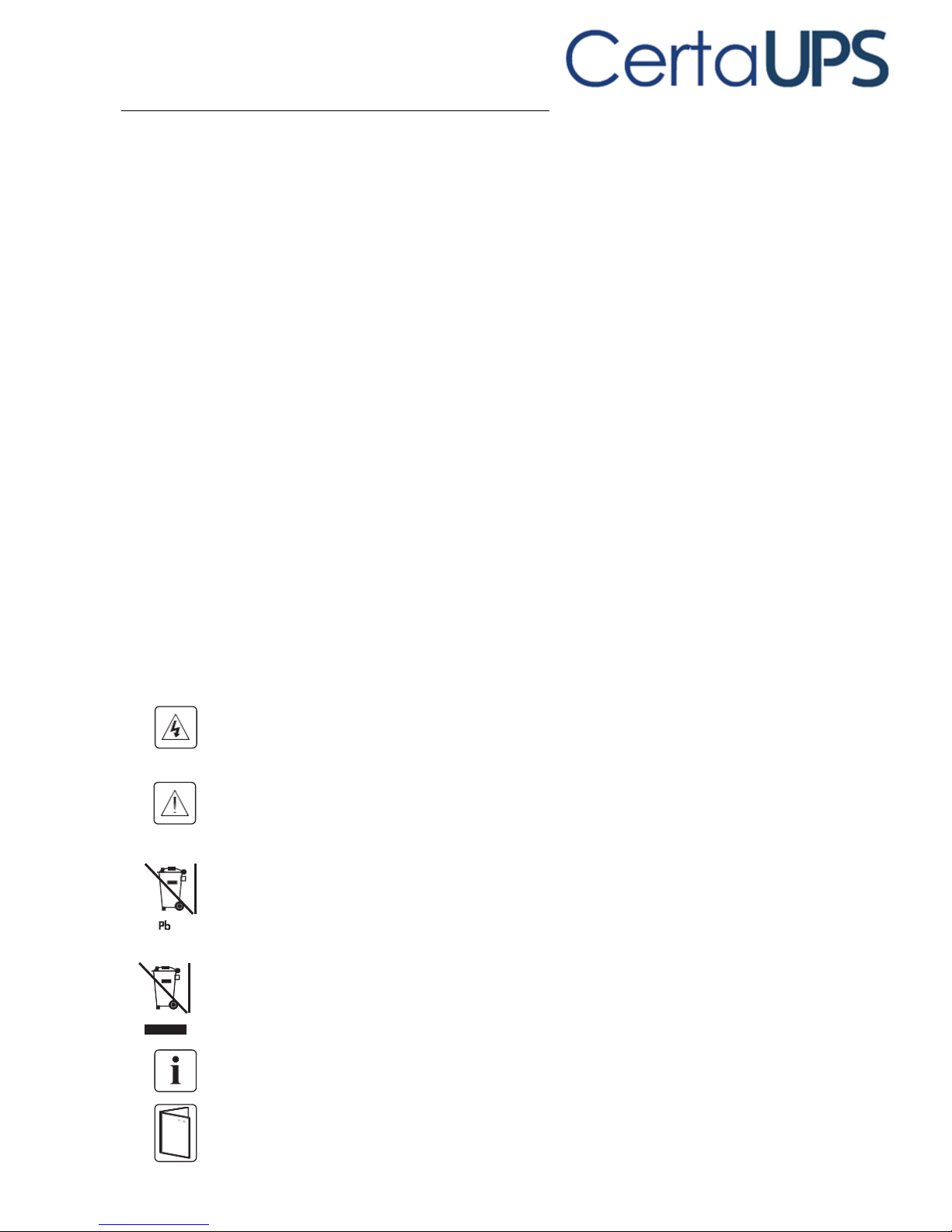
RISK OF ELECTRIC SHOCK - Observe the warning associated with the risk of electric
shock.
Important instructions that must always be followed.
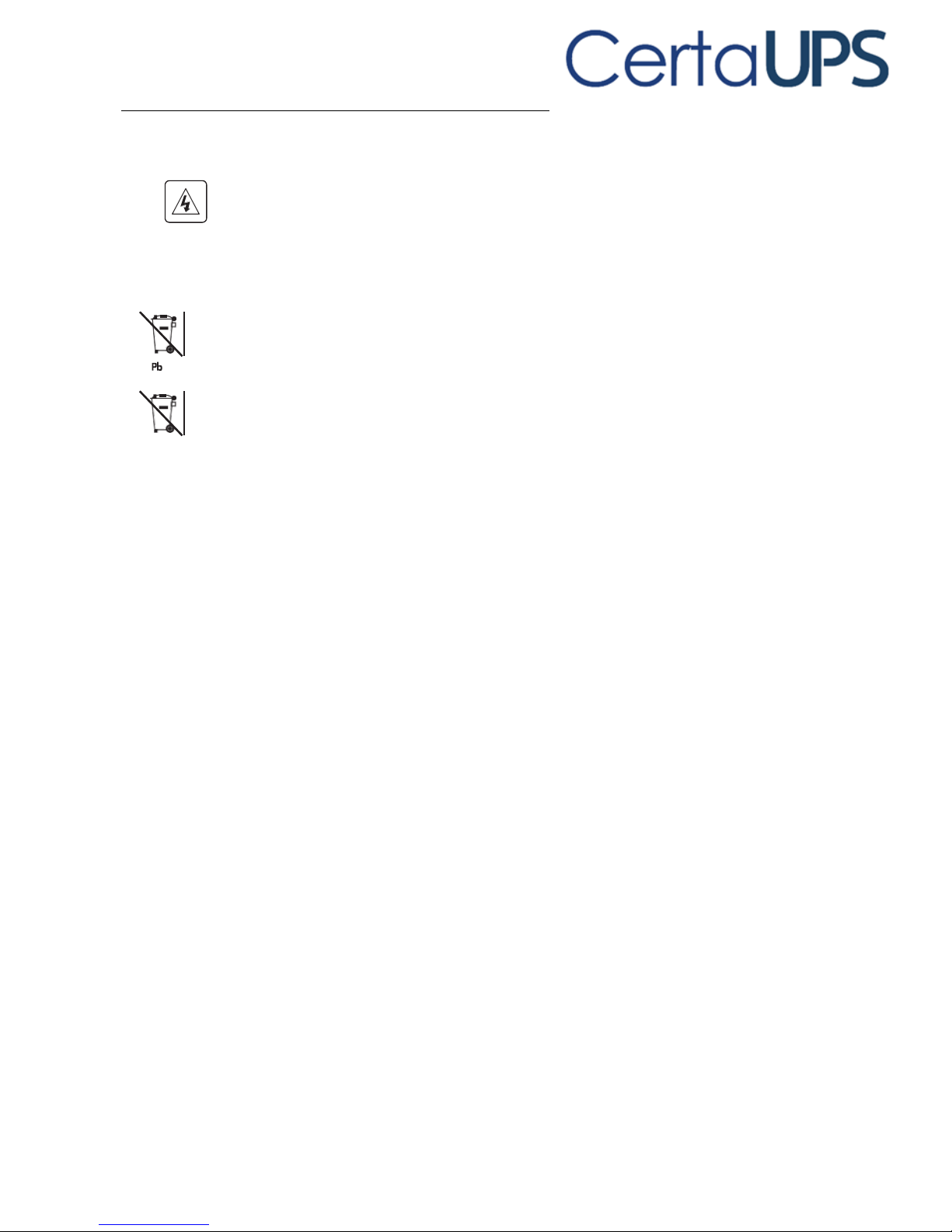
Do not dispose of the UPS or the UPS batteries in general waste.
This product contains sealed lead acid batteries and must be disposed as is explained
in this manual. For more information, contact your local recycling or hazardous waste
center.
This symbol indicates that you should not discard waste electrical or electronic
equipment (WEEE) in general waste. For proper disposal, contact your local recycling
or hazardous waste center.
Information, advice, help.
Refer to the user manual of UPS accessories.
Page 3

Personal Safety
RISK OF VOLTAGE BACKFEED. The system has its own power source (the
batteries). Isolate the UPS and check for hazardous voltage upstream and
downstream during operation. Terminal blocks may be energized even if the
system is disconnected from the AC power source.
Dangerous voltage levels are present within the system. It should be opened
exclusively by qualified service personnel.
The system must be properly grounded.
The batteries supplied within the system contain small amounts of toxic
materials. To avoid accidents, the directives listed below must be observed:
- Servicing of batteries should be performed or supervised by personnel
knowledgeable about batteries and the required safety precautions.
- When replacing batteries, replace with the same type and number of batteries
or battery packs.
- Do not dispose of batteries in a fire. The batteries may explode.
- Batteries constitute potential danger via electrical shock or burns. The shortcircuit current could be extremely high.
Precautions must be taken whenever handling batteries:
- Wear rubber gloves and boots.
- Do not lay tools or metal components on top of batteries.
- Disconnect charging source prior to connecting or disconnecting battery
terminals.
- Determine if batteries are inadvertently grounded. If inadvertently grounded,
remove source from ground. Contact with any part of a grounded battery can
result in electrical shock. The likelihood of this occurring can be reduced if
such grounds are removed during installation and maintenance (applicable to
equipment and remote battery supplies not having a grounded supply circuit).
Page 4

Product safety
The UPS connection procedures and operational instructions described within
this manual must be followed in the indicated order.
An additional circuit breaker with breaking capacity 6kA shall be used between
power source and input when installation this unit
CAUTION - To reduce the risk of fire, the unit connects only to a circuit provided
with branch circuit overcurrent protection for :
63A rating, for 6kVA models,
100A rating, for 10kVA models
The upstream circuit breaker for Normal AC/Bypass AC must be easily accessible.
The unit can be disconnected from AC power source by opening this circuit
breaker.
An additional AC contactor is used for back feed protection and must comply with
IEC/EN 62040-1 (the creep age and clearance distances shall meet the basic
insulation requirements for pollution degree 2).
Disconnection and overcurrent protection devices shall be provided by others for
permanently connected AC input (Normal AC/Bypass AC) and AC output circuits.
Check that the indications on the rating plate correspond to your AC powered
system and to the actual electrical consumption of all the equipment to be
connected to the system.
For PLUGGABLE EQUIPMENT, the socket-outlet shall be installed near the
equipment and shall be easily accessible
Never install the system near potential liquid hazards or in an excessively
damp/humid environment.
Never let foreign objects enter the UPS system.
Do not house within and enclosed space to ensure adequate ventilation and
proper heat dissipation
Never expose the system to direct sunlight or source of heat.
If the system must be stored prior to installation, storage must be in a dry place.
The admissible storage temperature range is -25ºC to +60ºC with battery (-15ºC
to +40ºC without battery).
Page 5

Special precautions
The unit is heavy: wear safety shoes and ideally use a vacuum lifter for handling
safety.
All handling operations will require at least two people (unpacking, lifting,
installation within a rack system).
Straps are provided only for removing the UPS from its packaging (do not use
the straps to carry the unit) improper handling may cause personal injury
and/or damage to the UPS.
- keep 12in / 30cm minimum distance between the straps
- lift the unit carefully and keep it at low height
- keep the unit horizontal during unpacking.
If the UPS is to remain unpowered for an extended period, the UPS must be
energized for a minimum period of 24 hours at least once every 6 months (for a
normal storage temperature less than 25°C). This charges the battery, avoiding
possible irreversible damage.
During the replacement of the Battery Module, it is imperative to use the same
type and number of element as the original Battery Module provided with the
UPS to maintain operational performance and safety.
Page 6

Contents
1. INTRODUCTION .............................................................................. 0
1.1 ENVIRONMENTAL PROTECTION ............................................................................... 0
2. PRESENTATION ............................................................................... 2
3. INSTALLATION ................................................................................ 6
3.1 INSPECTING THE EQUIPMENT .................................................................................. 6
3.2 UNPACKING THE UNIT .......................................................................................... 6
3.3 CHECKING THE ACCESSORY KIT ................................................................................ 7
3.4 INSTALL THE UPS ................................................................................................. 8
3.5 INSTALL AND CONNECT EBM TO UPS .................................................................... 10
4. POWER CABLES CONNECTION ...................................................... 13
4.1 ACCESS TO TERMINAL BLOCKS ....................................................................... 13
4.2 PARALLEL SET UP ............................................................................................... 14
5. OPERATION .................................................................................. 15
5.1 CONTROL PANEL ................................................................................................ 15
5.2 LCD DESCRIPTION .............................................................................................. 16
5.3 DISPLAY FUNCTIONS ........................................................................................... 19
5.4 USER SETTINGS ................................................................................................. 20
5.5 UPS STARTUP AND SHUTDOWN ............................................................................ 21
5.6 LCD OPERATION ................................................................................................ 22
6. COMMUNICATION ........................................................................ 29
6.1 COMMUNICATION PORTS .................................................................................... 29
6.2 NETWORK MANAGEMENT CARD (OPTIONAL) ......................................................... 30
6.3 UPS MANAGEMENT SOFTWARE ........................................................................... 31
Page 7

7. UPS MAINTENANCE ...................................................................... 32
7.1 EQUIPMENT CARE .............................................................................................. 32
7.2 TRANSPORTING THE UPS .................................................................................... 32
7.3 STORING THE EQUIPMENT ................................................................................... 32
7.4 REPLACING BATTERIES ......................................................................................... 33
7.5RECYCLING THE USED EQUIPMENT .......................................................................... 35
8. TROUBLESHOOTING ..................................................................... 35
8.1 TYPICAL ALARMS AND FAULTS ............................................................................... 36
8.2 SILENCING THE ALARM ........................................................................................ 40
9. SPECIFICATIONS ............................................................................ 41
9.1 MODEL SPECIFICATIONS ...................................................................................... 41
10 GLOSSARY ................................................................................... 46
Page 8
0
1. Introduction
Thank you for selecting C500® G2 UPS to protect your electrical equipment. The
C500® G2 UPS has been designed with the utmost care.
We recommend that you take the time to read this manual to take full advantage
of the many features of your UPS (Uninterruptible Power System).
Before installing your C500® G2 UPS, please read the booklet including the safety
instructions. Then follow the instructions within this manual.
1.1 Environmental protection
Products are developed with an environmentally friendly design approach.
Substances
This product does not contain CFCs, HCFCs or asbestos.
Packing
To improve waste treatment and facilitate recycling, separate the various
packaging components.
•
The cardboard we use comprises of over 50% of recycled cardboard.
•
Sacks and bags are made of polyethylene.
•
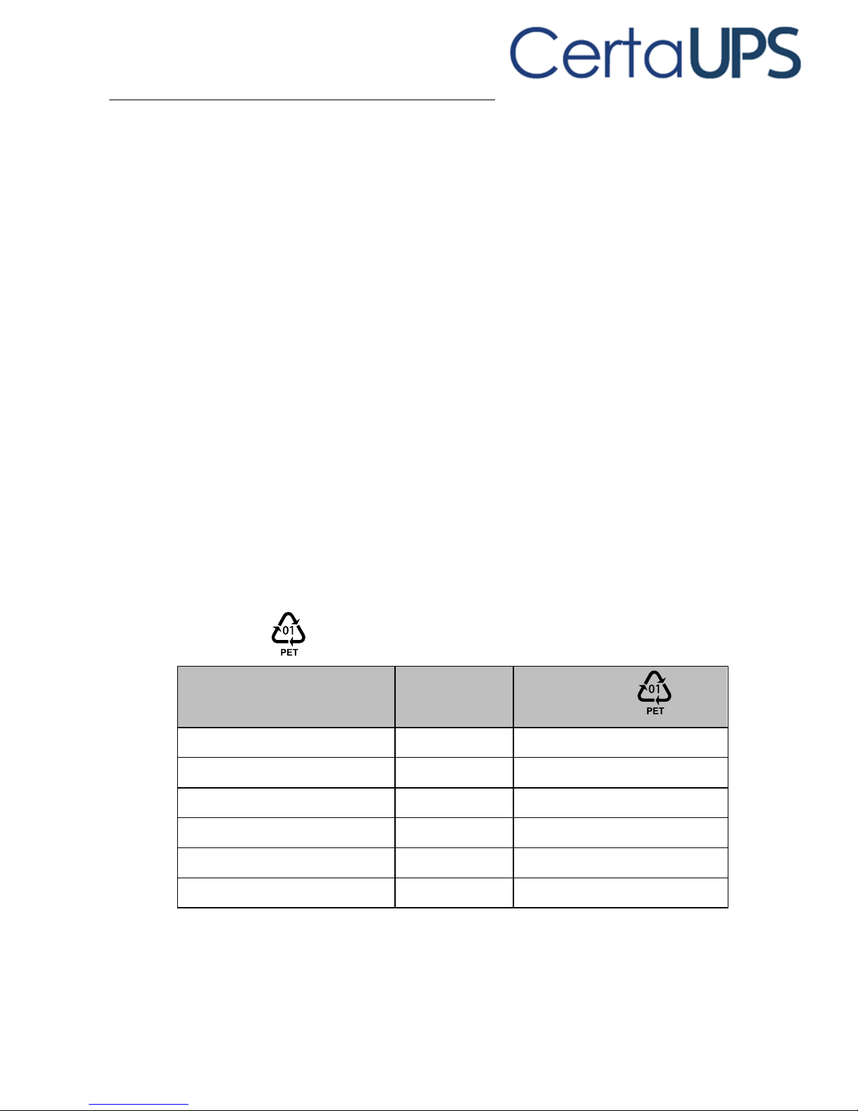
Packing materials are recyclable and bear the appropriate identification
symbol
Materials
Abbreviations
Number in
the symbols
Polyethylene terephthalate
PET 01
High-density polyethylene
HDPE
02
Polyvinyl chloride
PVC
03
Low-density polyethylene
LDPE
04
Polypropylene
PP
05
Polystyrene
PS
06
Follow all local regulations for the disposal of packing materials.
Page 9

1
Product
The product is made up of recyclable materials.
Dismantling and destruction must take place in compliance with all local
regulations concerning waste disposal. At the end of its service life, the product
must be transported to a processing center for electrical and electronic waste.
Battery
The product contains lead-acid batteries that must be processed according to
applicable local regulations concerning batteries.
The battery may be removed to comply with regulations and responsibly disposed
of.
The C500® G2 uninterruptible power system (UPS) protects your sensitive
electronic equipment from the most common power problems, including power
failures, power sags, power surges, brownouts, line noise, high voltage spikes,
frequency variations, switching transients, and harmonic distortion.
Power outages can occur when you least expect it and power quality can be
erratic. These power problems have the potential to corrupt critical data, destroy
unsaved work sessions, and damage hardware - causing hours of lost productivity
and expensive repairs.
With the C500® G2, you can safely eliminate the effects of power disturbances
and protect the integrity of your equipment. Providing outstanding performance,
reliability and protection.
The C500® G2’s unique benefits include:
True online double-conversion technology with high power density, utility
frequency independence, and generator compatibility.
Selectable High Efficiency mode of operation.
Standard communication options: one RS-232 communication port, one
USB communication port, one dry in port and dry out port.
Optional connectivity cards with enhanced communication capabilities.
Firmware that is easily upgradable without a service call.
Page 10
2
2. Presentation
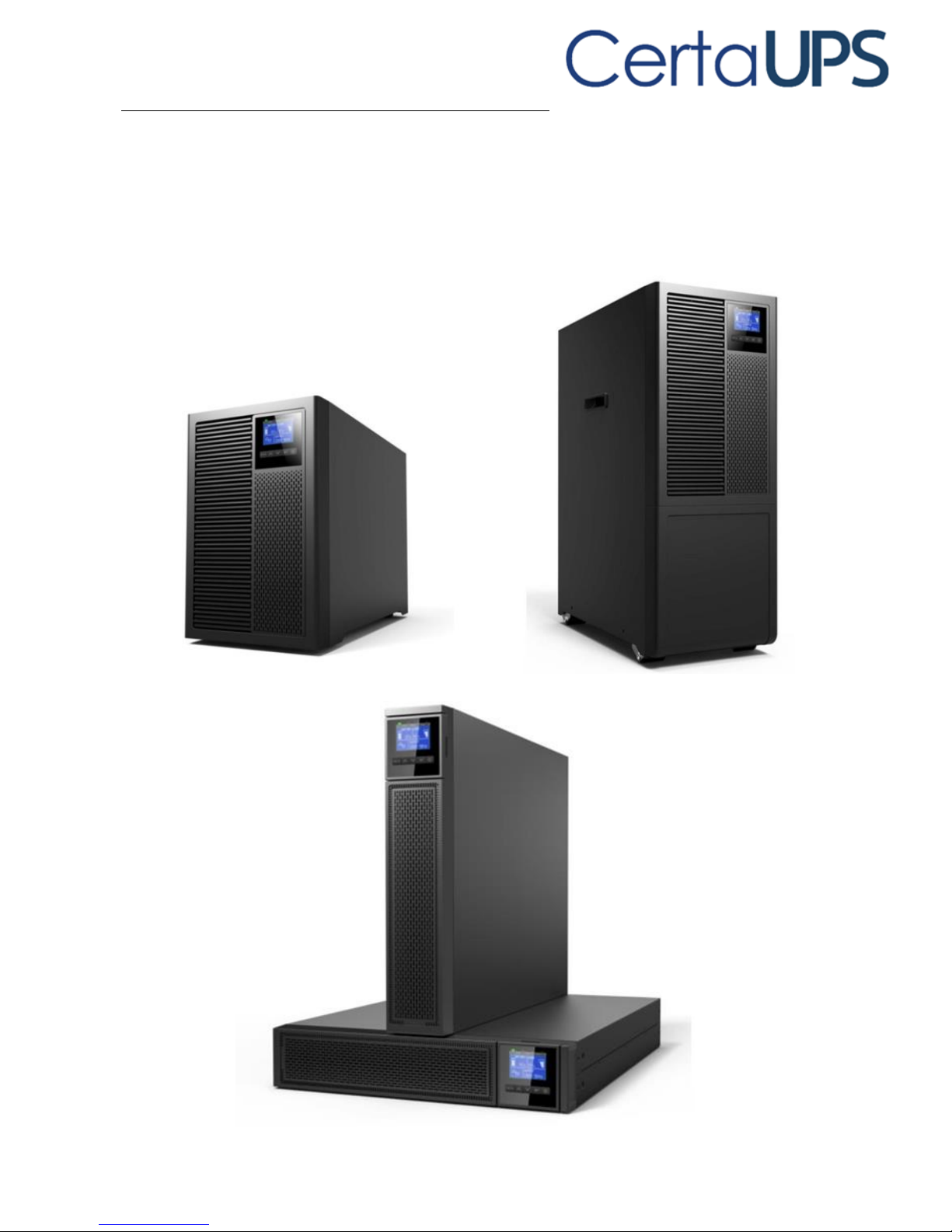
Front panel
Page 11
3
Rear panels
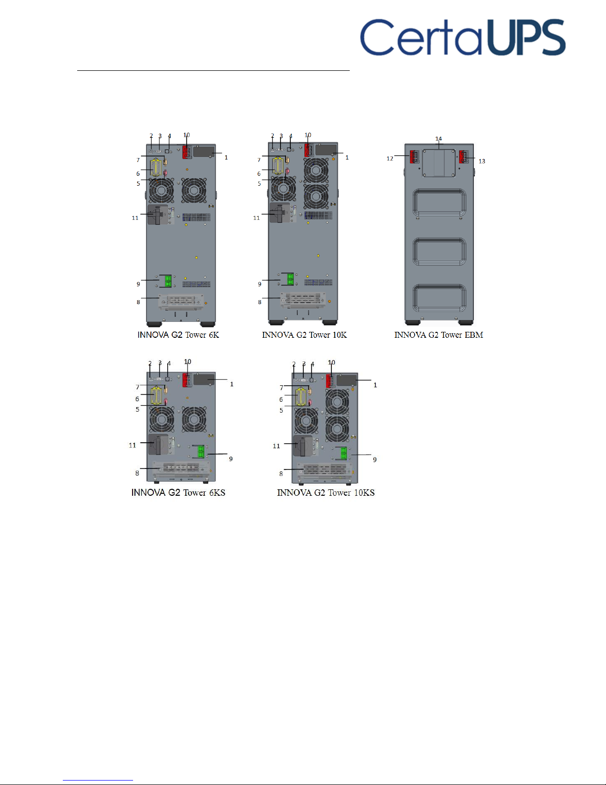
TOWER model
1. Intelligent Expansion slot
2. USB
3. RS232
4. RJ11 (only for RT model)
5. EPO
6. PARALLEL card (optional)
7. DRY IN/OUT
8. Input /Output terminal
(Standard model 5pole, IPL,
IPN, PE, OPL, OPN; long
backup model has 2 version,
one is 5 Pole. Another is
7pole. 7pole add bat+, bat-,
and no external battery
connector #10.)
9. Input switch
10. External battery connector
11. Maintenance bypass switch
(optional)
12. EBM connector
13. EBM connector
14. Fuse board cover (replace
EBM fuse)
Page 12
4
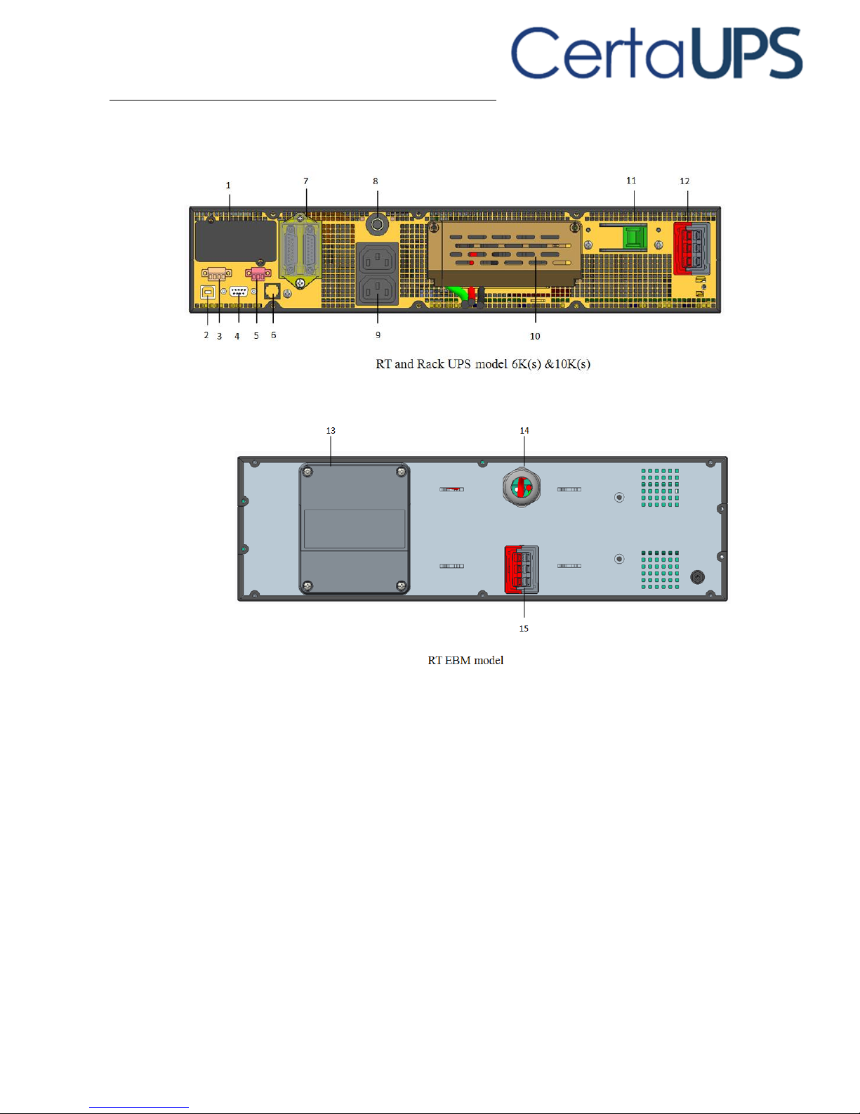
RT model
1. Intelligent Expansion slot
2. USB
3. DRY IN/OUT
4. RS232
5. EPO
6. RJ11 (connect to PDU, only
for RT model)
7. PARALLEL card (optional)
8. Output breaker
9. Output socket
10. Input /Output terminal
(4pole IPL, IPN, OPL, OPN. PE is
screw)
11. Input breaker (optional)
12. EBM connector
13. Fuse board cover (replace
EBM fuse)
14. EBM plug
15. EBM connector
Page 13
5
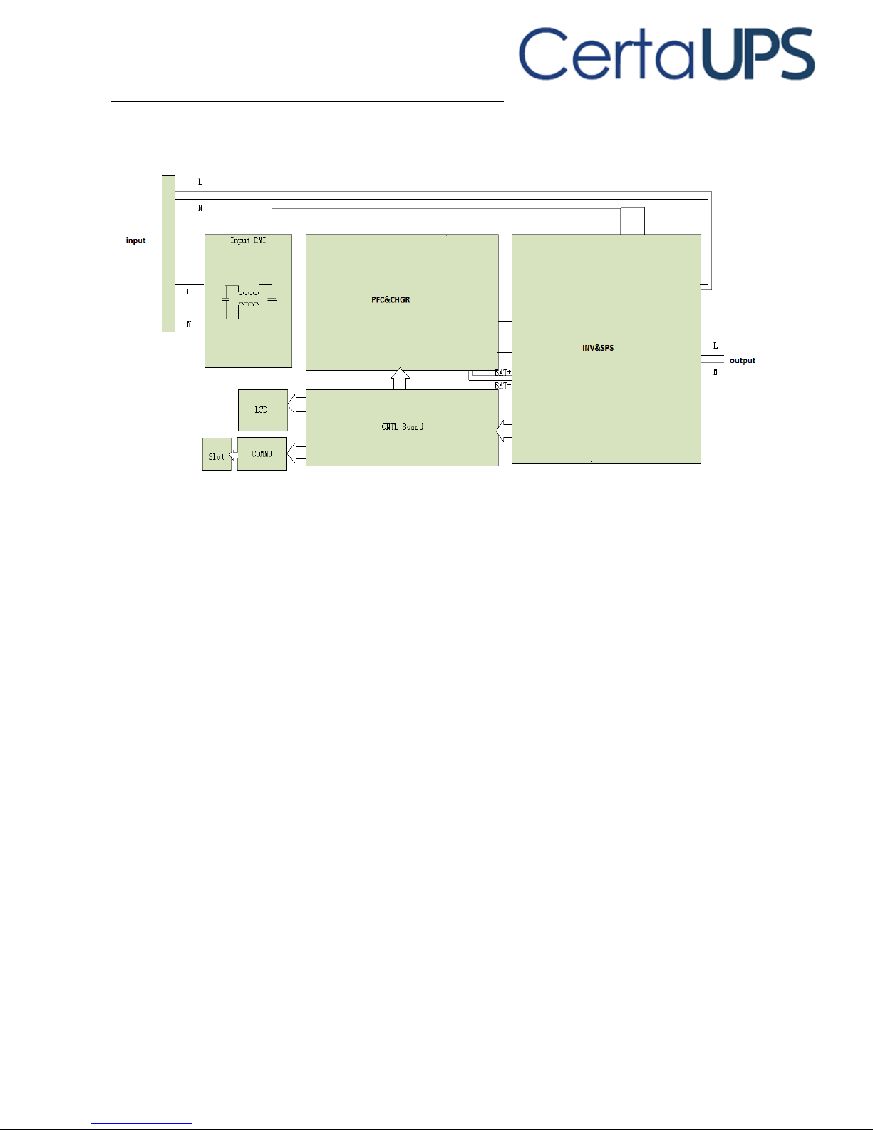
Circuit diagram
Page 14
6
3. Installation
3.1 Inspecting the equipment
If any equipment has been damaged during shipment, keep the packing materials
for the carrier or place of purchase and file a claim for shipping damage. If you
discover damage after acceptance, file a claim for concealed damage.
Check the battery recharge date on the shipping carton label. If the date has
passed and the batteries were never recharged, do not use the UPS. Contact your
service representative.
3.2 Unpacking the Unit
Unpacking the unit in a low-temperature environment may cause
condensation to occur in and on the cabinet. Do not install the cabinet until
the inside and outside of the cabinet are absolutely dry (hazard of electric
shock).
The cabinet is heavy (see page 42). Follow Special precautions provided on
the carton.
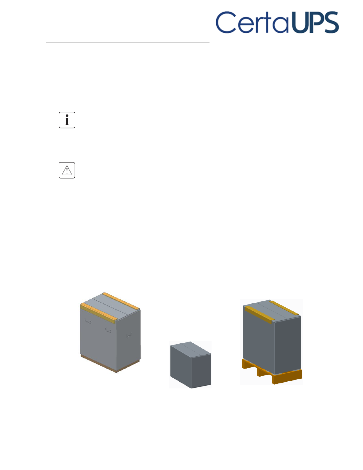
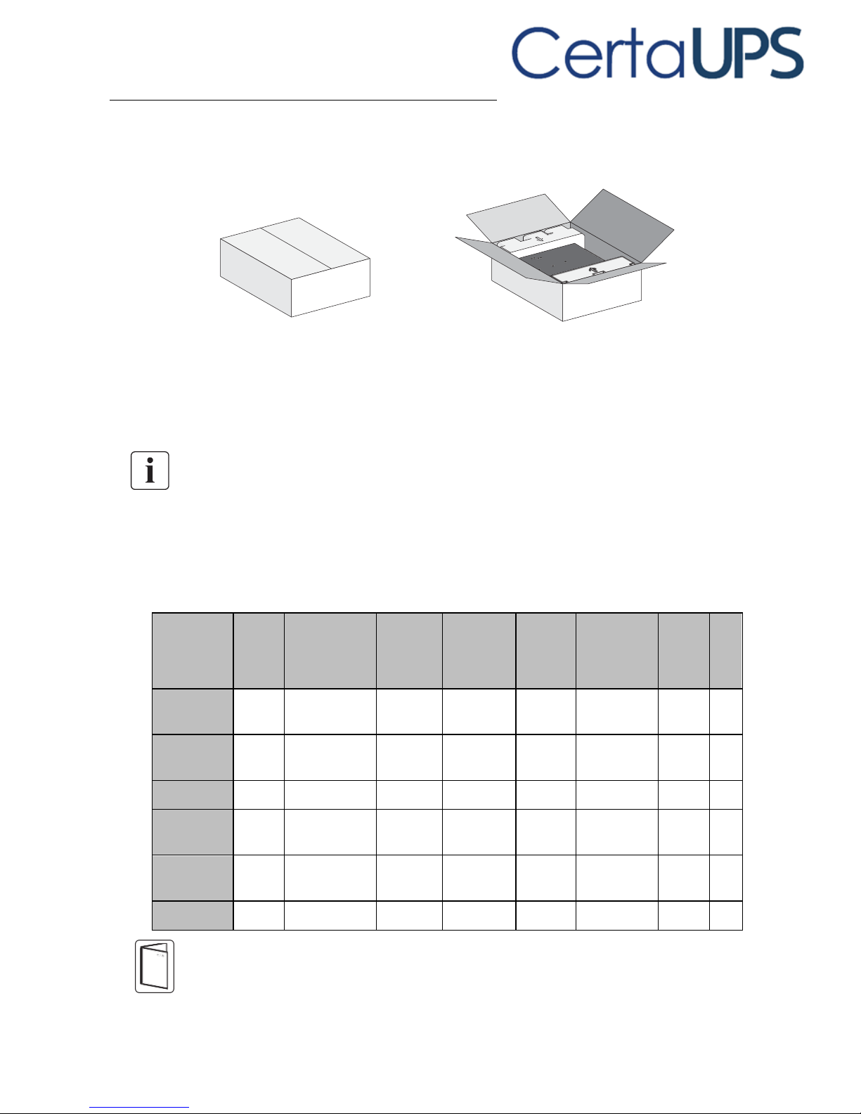
Unpack the equipment and remove all the packing materials and shipping carton.
Note: Do not lift the unit’s front panel and rear panel.
Tower model:
Page 15
7
Rack model:
Discard or recycle the packaging in a responsible manner, or store it for future use.
Place the cabinet in a protected area that has adequate airflow and is free of
humidity, flammable gas, and corrosion.
Packing materials must be disposed of in compliance with all local regulations
concerning waste. Recycling symbols are printed on the packing materials to
facilitate sorting.
3.3 Checking the accessory kit
Verify that the following additional items are included with the unit:
Battery
power
cable
USB
communicatio
n cable
Dry
contractor
EPO
contractor
Stabilizer
bracket
Extension
plate of
Stabilizer
bracket
Ear
bracke
t
Rai
l
kit
Tower UPS
6K/10K
X
X X
Tower UPS
6KS/10KS
X
X
Tower EBM
X
X
RT UPS
6K/10K
X
X X X
RT UPS
6KS/10KS
X
X X X
RT EBM
X
X
If you ordered other accessories, refer to specific user manuals to check the
packing contents.
Page 16
8
3.4 Install the UPS
Tower model installation:
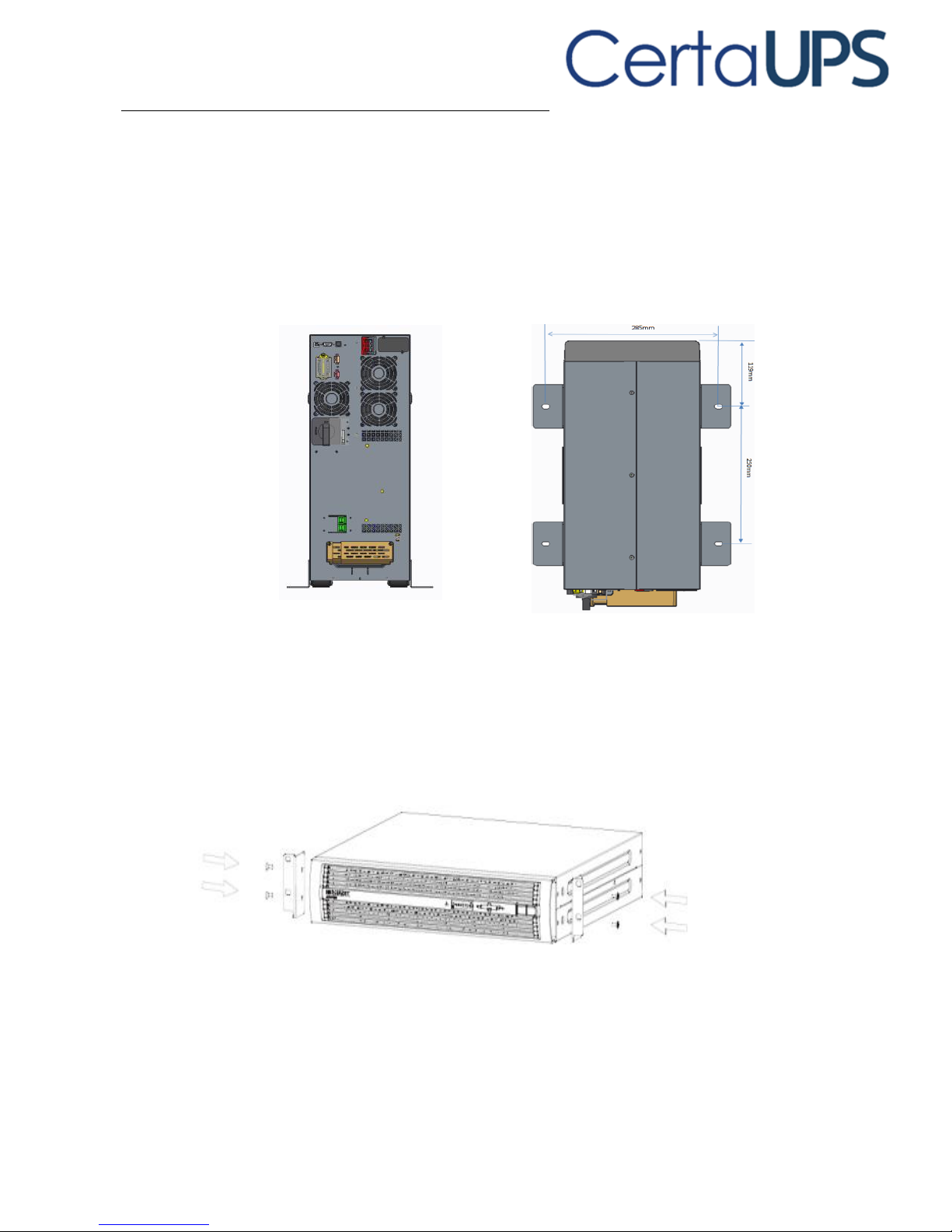
Place the unit on a flat, stable surface in its final location.
Always keep 150 mm of free space behind the rear panel.
If installing additional unit, place them next to the first unit in their final location.
If installing Stabilizer bracket, place 4pcs bolts to the final location previously.
Bolt’s position is as below.
RT model installation:
Rack position installing
1. Install Ear bracket to the unit.
Page 17
9
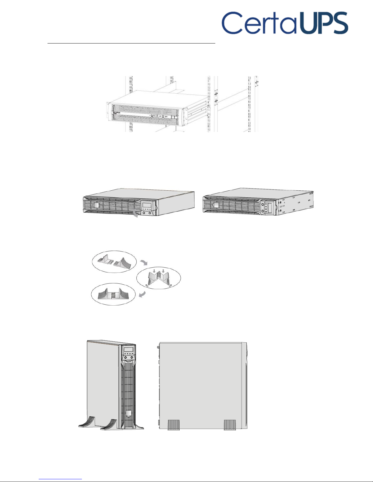
2. Install the unit to rack cabinet in a suitable U-space (Previously install Rail kit
refer to its user manual).
Tower position installing
1. Rotate the LCD model to tower direction
2. Set up the Stabilizer bracket as below.
3. Take the unit to Stabilizer bracket.
Page 18
10
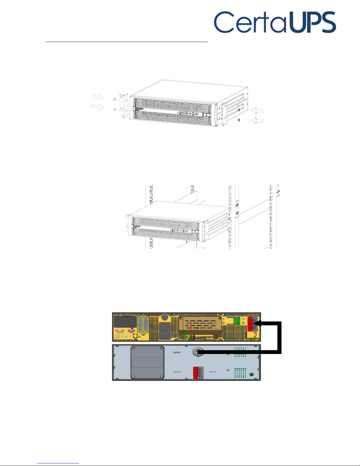
3.5 Install and connect EBM to UPS
Tower EBM installation:
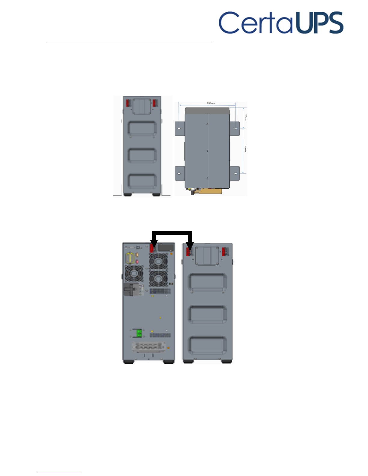
1. Place the unit on a flat, stable surface in its final location.
2. If installing Stabilizer bracket, place 4pcs bolts to the final location previously.
Bolt’s position is as below.
3. Connect to UPS with Battery power cable.
Page 19
11
RT EBM installation:
Rack position installing
1. Install the Ear brackets to both sides of the unit.
2. Mount the ups within a 19” rack cabinet in a suitable space utilizing the
appropriate rail kit (refer to separate rail kit instructions).
3. Connect to UPS with Battery power cable.
Page 20
12
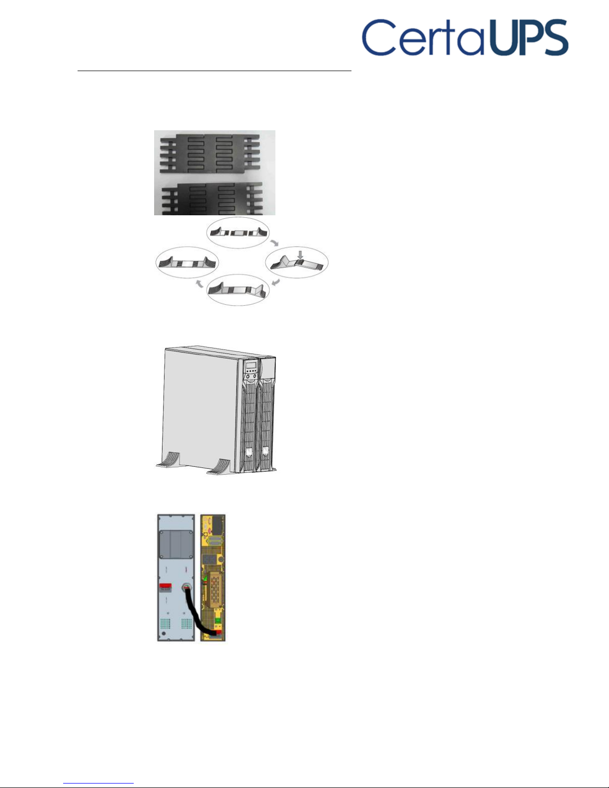
Tower position installing
1. Set up the Extension plate as below and install to Stabilizer bracket from UPS.
2. Take the unit to Stabilizer bracket.
3. Connect to UPS with Battery power cable.
4. If installing additional unit, place to left and connect the right unit in their final
location.
Page 21
13
4. Power cables connection
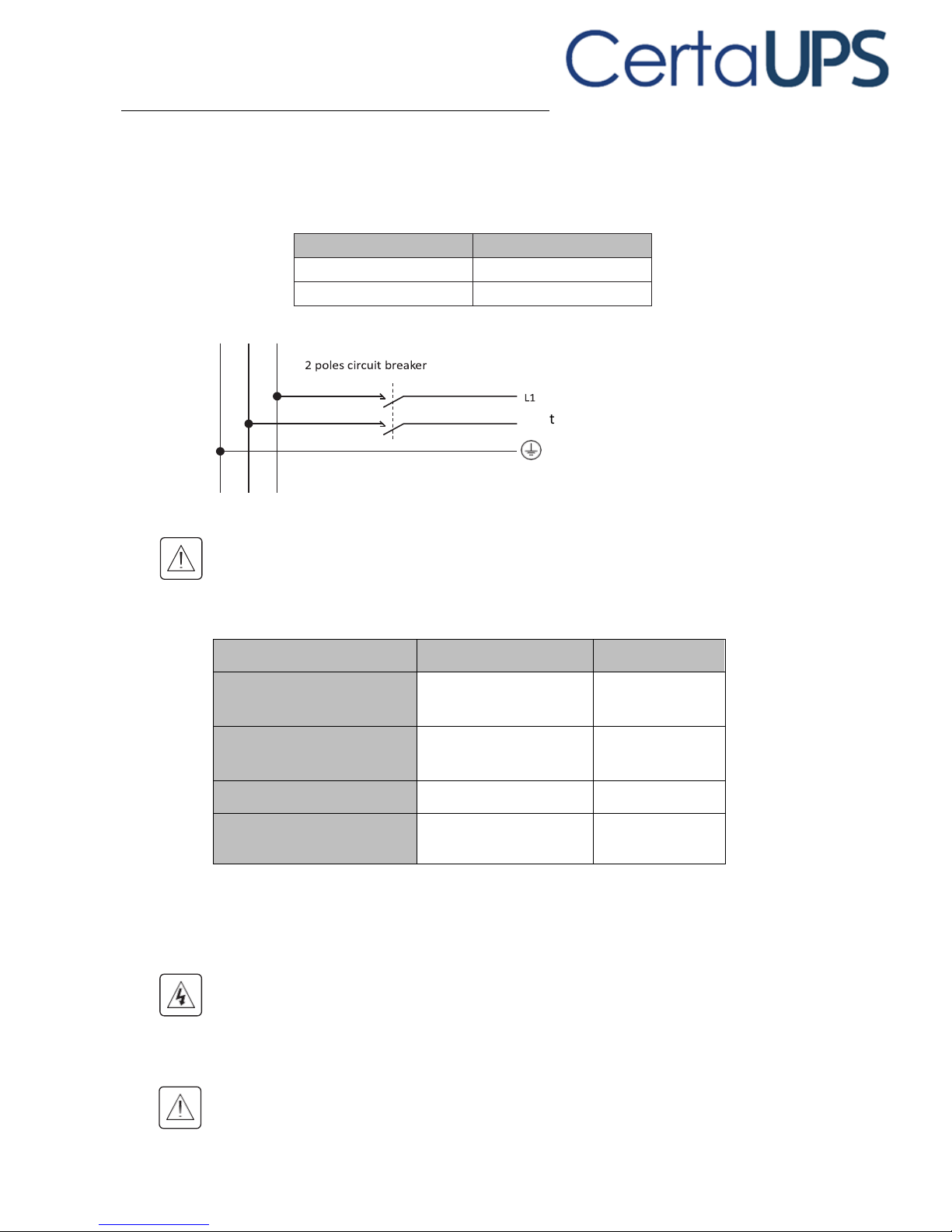
Recommended protective devices and cable cross-sections
Recommended upstream protection
UPS power rating
Upstream circuit
6000VA
D curve – 63A
10000VA
D curve – 100A
to UPS Normal AC / Bypass AC source
G N(L2) L1
Read the Safety instructions on page 3 regarding back-feed protection
requirements.
Recommended cable cross-sections
Model
6K
10K
Protective earthing conductor
Min cross section
6mm2 (8AWG)
10mm2 (6AWG)
Input L, N, G
Min conductor cross section
6mm2 (8AWG)
10mm2(6AWG)
Input fuse
80A
100A
Output L,N,
Min conductor cross section
6mm2 (8AWG)
10mm2(6AWG)
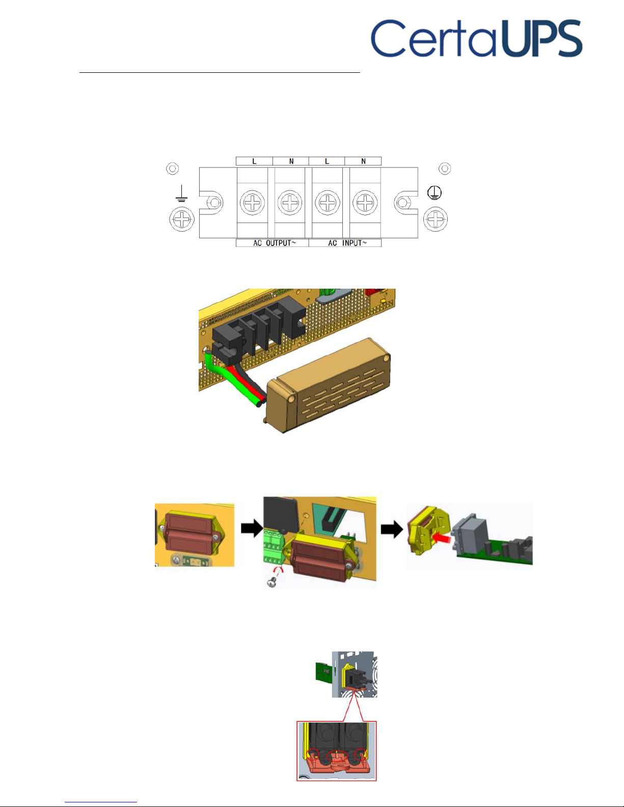
4.1 Access to terminal blocks
Remove the terminal blocks cover (two screw)
High leakage current:
Earth connection essential before connecting supply.
Common input/output sources connection
This type of connection must be carried out by qualified electrician.
N(L2)
Page 22
14
Before carrying out any connection check that the upstream protection devices
(Normal AC source and Bypass AC source) are open "O" (Off).
Always connect the ground wire first
1. Connect the AC cable to terminal blocks as indicator on rear panel
2. Install back the TB Cover
4.2 Parallel set up
1. Remove the parallel kit and insert the parallel PCB.
2. Install parallel kit back to the unit and insert the parallel cable
3. Re-install cover to the kit to secure the plug connection and prevent damage.
Page 23
15
5. Operation
5.1 Control panel
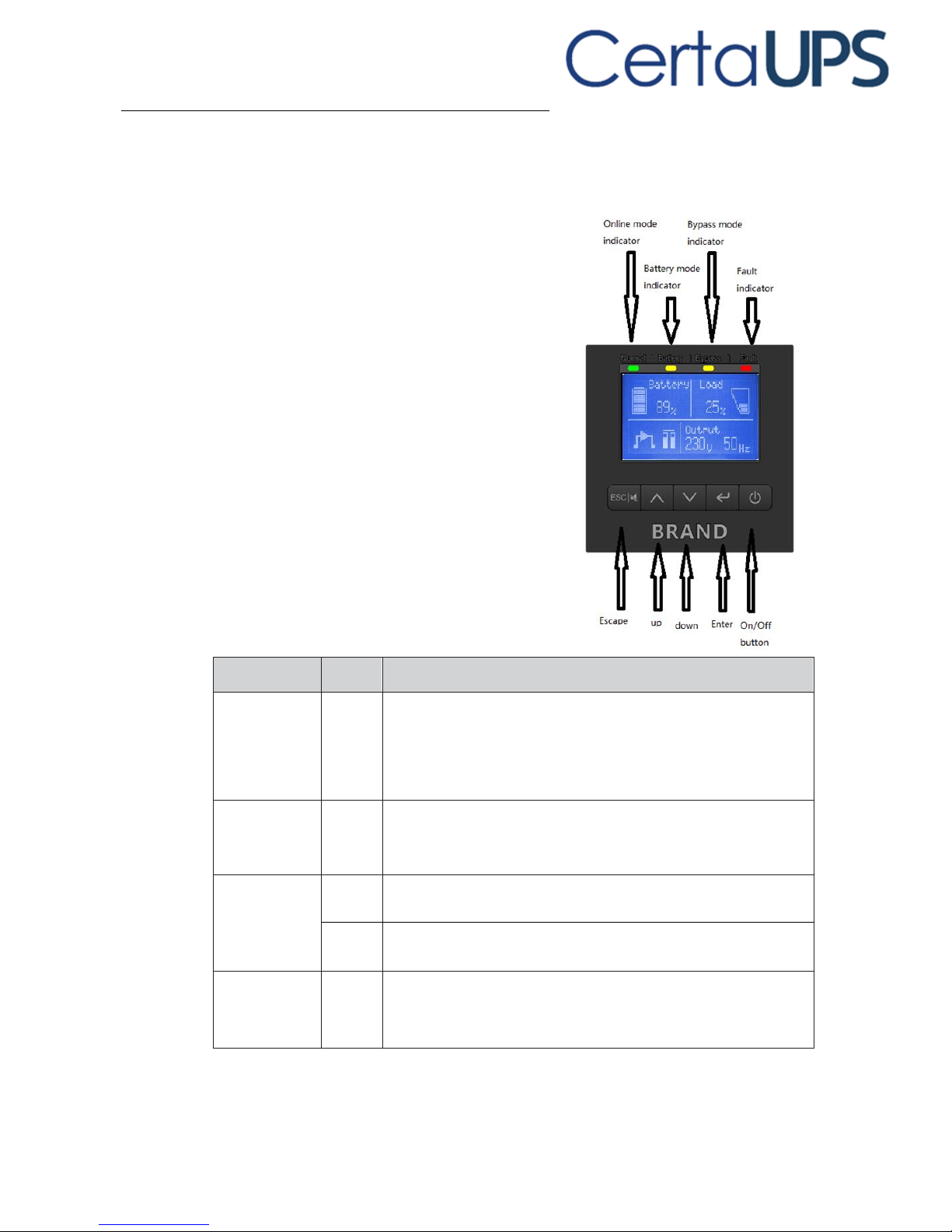
The UPS has a five-button graphical LCD. It
provides useful information about the UPS
itself, load status, events, measurements
and settings.
The following table shows the indicator
status and description:
Indicator
Status
Description
Normal
(Green)
On
The UPS is operating normally on Online or on High
Efficiency mode.
Battery
(Orange)
On
The UPS is on Battery mode.
Bypass
(Orange)
On
The UPS is on Bypass mode.
Flash
The UPS is on Standby mode.
Fault
(Red)
On
The UPS has an active alarm or fault. See trouble- shooting on
page 36 for additional information.
Page 24
16
5.2 LCD description
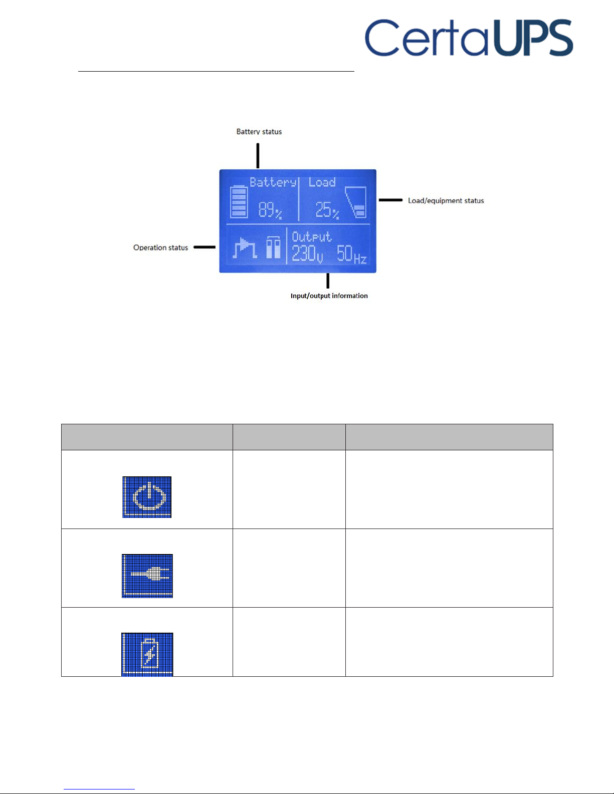
The LCD backlight automatically dims after 2 minutes of inactivity (except when a
fault is present). Press any button to restore the screen.
The following table describes the status information provided by the UPS
Note: If other indicator appears, see troubleshooting for additional information.
Operation status
Cause
Description
Standby mode
The UPS is Off.
UPS is operating without output.
Online mode
The UPS is operating
normally.
The UPS is powered and protecting the
equipment.
Battery mode
A utility failure has
occurred and the UPS is
on Battery mode.
The UPS is powering the equipment with
battery power.
Prepare your equipment for shutdown.
Page 25
17
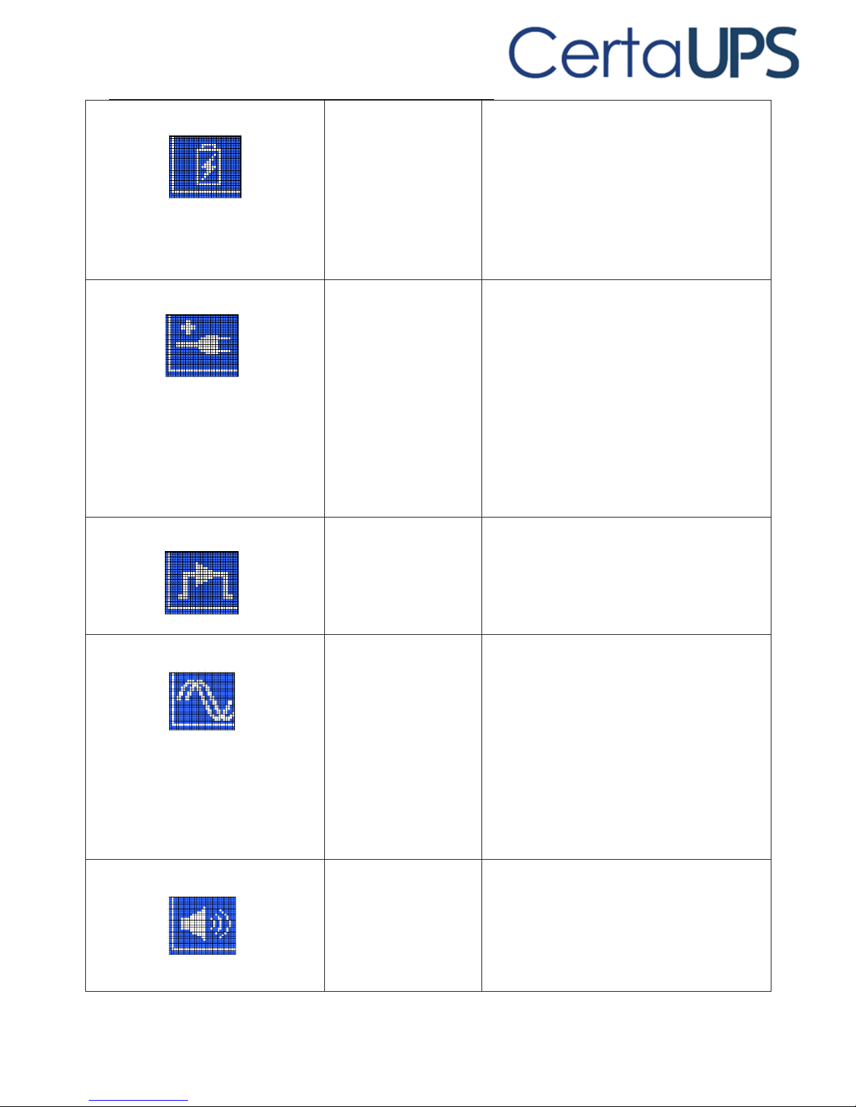
End of backup time
1 beep every 1 seconds
The UPS is on Battery
mode and the battery is
running low.
This warning is approximate, and the actual
time to shutdown may vary significantly.
High Efficiency mode
The UPS is operating
on High Efficiency
mode.
Once mains power is lost or abnormal, the
UPS would transfer to Line mode or Battery
mode and the load is supplied continuously.
1. The function could be enabled through
the LCD setting or the software (WinPower,
etc.)
2. It is important to note that the transfer
time of UPS output from HE mode to battery
mode is about 10ms. But it is still too long
for some sensitive equipment
Bypass mode
An overload or a fault
has occurred, or a
command has been
received, and the UPS
is in Bypass mode.
Equipment is powered but not protected by
the UPS.
Converter mode
The UPS is operating
on converter mode.
In converter mode, the UPS would free run
with fixed output frequency (50Hz or 60Hz).
Once the mains is loss or abnormal, the UPS
would transfer to battery mode and the load
is supplied continuously.
1. The function could be enabled through
the LCD setting or the software (WinPower,
etc.).
2. The load should be derating to 60% in
converter mode.
Warning
There are warnings
during the operation of
UPS. Normally these
problems don’t
prevent normal
operation
The UPS continues working, but the problem
should be identified and resolved
immediately or it could prevent normal
operation of the UPS.
Page 26
18
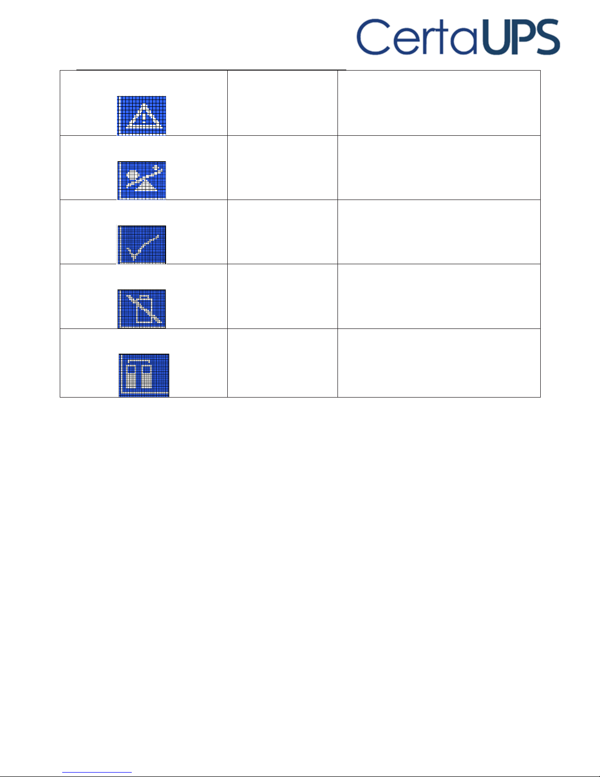
Fault
A Serious problem has
been detected.
The UPS would directly cut off the output or
transfer to bypass, and alarm.
Overload
The load exceeds the
capacity of the UPS
Excess load should be removed to decrease
the load placed on the UPS
Battery test
UPS is executing a
battery test
The UPS is performing a Battery test. This is
normal self-maintenance by the UPS and is
part of normal operation
Battery fail
The UPS has detected
a fault or a battery is
disconnected
The symbol of battery failure would be
shown and UPS will alarm. The fault should
be investigated by a qualified UPS technician
UPS Parallel
Using two or three UPS
for heavy load or
redundancy
Two or three UPSs are operating in parallel
Page 27

19
5.3 Display functions
Use the two middle buttons (▲ and ▼ ) to scroll through the menu structure.
Press the Enter ( ) button to select an option. Press the ESC button to
cancel or return to the previous menu.
When starting the UPS, the display is in the default UPS status summary screen.
Main menu
Submenu
Display information or Menu function
UPS status
[status summary screen] / [Alarm] / [Battery
charging/Volt/level/remain time] / [mode/ Para Num. /Running
Measurements [Load] W VA/ [Output/Current] A % /
[Output/Voltage] V Hz/ [Input/Voltage] V Hz /
[Battery] V % / [DC bus] V V /
[temperature] °C /[Battery remaining time] Min
Control
Single battery test
Starts a manual battery test for single UPS
Parallel UPS battery
Starts a manual parallel battery test
Single UPS turn off
Turns off one UPS in a parallel UPS system
Reset fault status
Clears active fault
Clear event log
Clears events
Restore factory set
Returns all settings to original values
Settings
Sets parameters
Event log
Event list
Identification
[Product type/model] / [Part/Serial number] / [UPS
firmware]
Page 28

20
5.4 User settings
The following table displays the options that can be changed by the user.
Submenu
Available settings
Default settings
Password
Key the password
USER
language
[English] [Chinese]
English
User password
[Disabled] [Enabled]
[Disabled]
Audible alarm
[Enabled] [Disabled]
[Enabled]
Output voltage
[208V] [220V] [230V] [240V]
Can be changed in Standby mode and
Bypass mode
[230V]
Output frequency
[Autosensing] [50Hz] [60Hz]
[Autosensing]
Power strategy
[Normal] [High efficiency] [Converter]
[Normal]
Auto bypass
[Enabled] [Disabled]
[Enabled]
Auto restart
[Enabled] [Disabled]
Authorize the product to restart
automatically when mains supply is
restored after a complete discharge
[Enabled]
Dry in
[Disabled] [SON] [SOFF] [Maintain
bypass]
[Disabled]
Dry out
[Loaded power] [On battery mode]
[Battery low] [Battery disconnected]
[Bypass output] [UPS normal]
[Loaded power]
Start on battery
[Enabled] [Disabled]
[Enabled]
External Battery Modules
[0~20]
[1]
External Battery AH Setting
[0~300]
[120]
Battery remaining time
[Disabled] [Enabled]
[Enabled]
Charger current
[0~4]
0~4A for standard model
[0~12]
0~12A for long backup model
[1.4A] for 6K, [2A] for 10K
[4A] for 6KS/10KS
Site wiring fault alarm
[Disabled] [Enabled]
[Disabled]
LCD contrast
[-5 ~ +5]
[+0]
Page 29

21
5.5 UPS startup and shutdown
Please switch off the connected loads before turning on the UPS, and switch on
connected devices one by one after the UPS is turned on. Switch off all connected
loads before turning off the UPS.
Starting the UPS with mains power present
Verify that the total equipment ratings do not exceed the UPS capacity to prevent
an overload alarm.
To start the UPS via mains power:
Check all the connection is correct.
Power on the UPS, the fans will start. After that, the LCD will show the default UPS
status summary screen.
Hold the button continuously for more than 1 second, the buzzer will beep 1s,
UPS starts to turn on.
A few seconds later, the UPS turns to Line mode. If the utility power is abnormal,
the UPS will transfer to Battery mode without output interruption to the UPS.
Starting the UPS on Battery only (cold Start)
Before using this feature, the UPS must have been powered by utility power with
output enabled at least once to ensure the unit is adequately charged.
After connecting the UPS to the battery, should wait 10s before pressing the
button for pre-charging the auxiliary power supply.
Battery start can be disabled. See “Start on battery” setting in user settings.
To start the UPS on battery:
Ensure all the connection are correct.
Pressing button continuously for more than 100ms, the UPS would be
powered on. At this time the fan begins to rotate. Then LCD will show the default
UPS status summary screen after UPS finishing initialization self-test.
Pressing button continuously for more than 1 second, the buzzer will beep for
300ms, UPS starts to turn on.
A few seconds later the UPS will transfer to Battery mode. If the mains power
comes back the UPS will transfer to Line mode without output interruption of the
UPS.
Page 30

22
UPS shutdown with mains power
To shut down the UPS with mains power:
Pressing the button continuously for more than 3 seconds and the buzzer
will beep for 300ms. After that the UPS will transfer to bypass mode immediately.
When completing the above action UPS output voltage is still present. In order to
cut off the UPS output simply remove the mains power supply. A few seconds later
the LCD display will shut down and no output power is available from the UPS
output terminal.
UPS shutdown without mains power
To shut down the UPS without mains power:
Power off the UPS by pressing the button continuously for more than 3
seconds, the buzzer will beep for 300ms at which point the UPS output will stop.
A few seconds later the LCD display will power off.
5.6 LCD operation
Except the default UPS status summary screen, the user can get more detailed
information about UPS current status, various measurements, previous event
records, UPS identification as well as change settings to fit the users own
requirements and optimize the function of UPS.
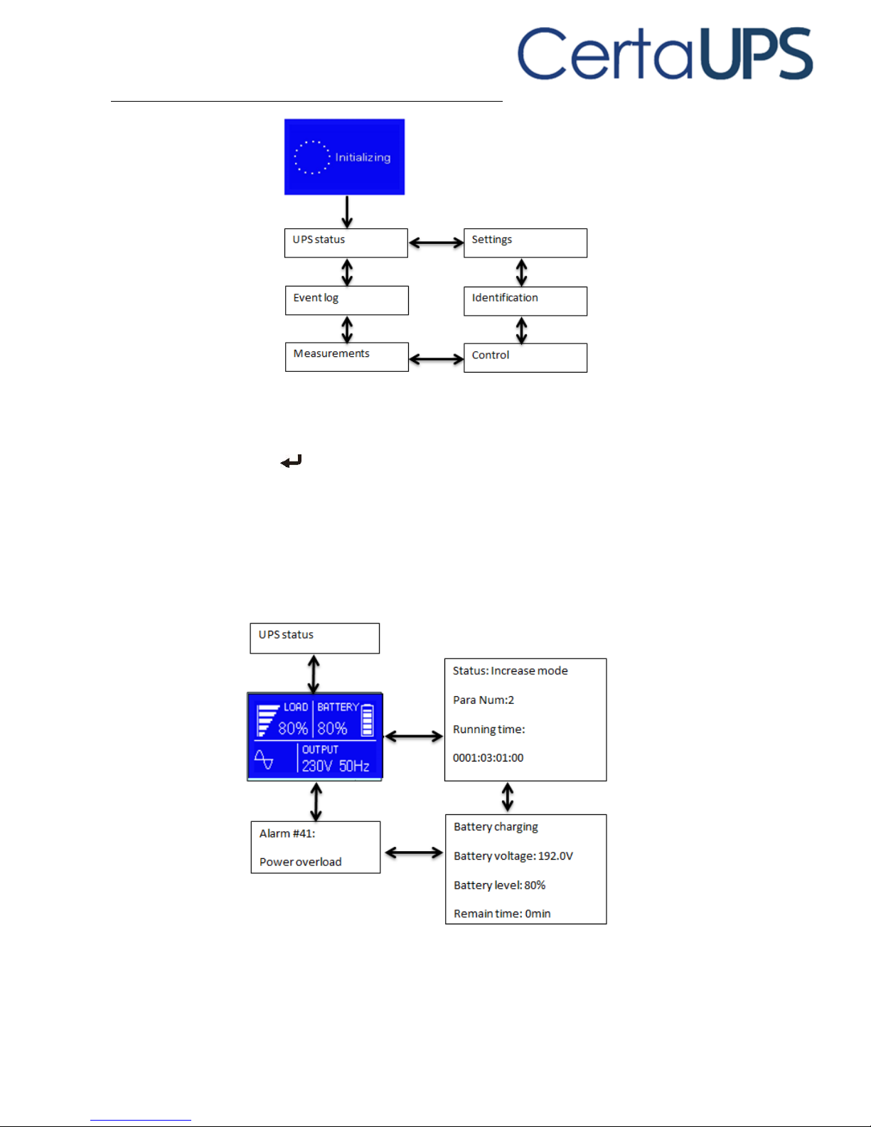
The main menu
In the default UPS status summary screen, when pressing ▲ or ▼ for less than 3
seconds, the UPS will display detailed information about alarm, battery and
system status.
In the default UPS status summary screen, when pressing ESC for more than 3
seconds, the display will enter main menu tree.
The main menu tree includes six branches:
UPS status
measurement
event log
control
identification menu
settings
Page 31
23
The UPS status menu
By pressing on the menu of “UPS status”, the display will enter the next UPS
status menu tree.
The content of UPS status menu tree is the same as the default UPS status
summary menu.
By pressing ESC for more than 3 seconds, the display will return to the last main
menu tree.
Page 32
24
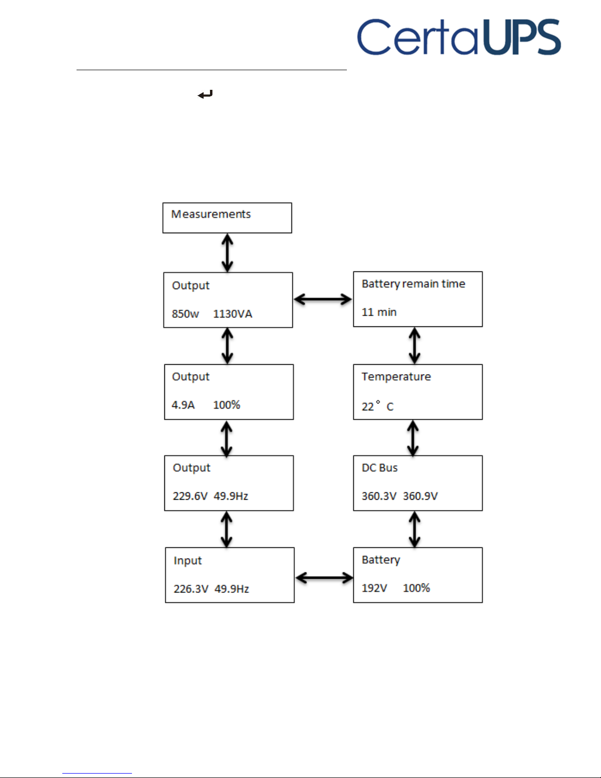
The measurement menu
By pressing on the menu of “Measurement”, the display will enter the
measurement menu tree.
A lot of detailed information can be checked here, including output voltage and
frequency, output current, load capacity, input voltage and frequency, etc.
By pressing ESC for more than 3 Seconds the display will return to the last main
menu tree.
Page 33
25
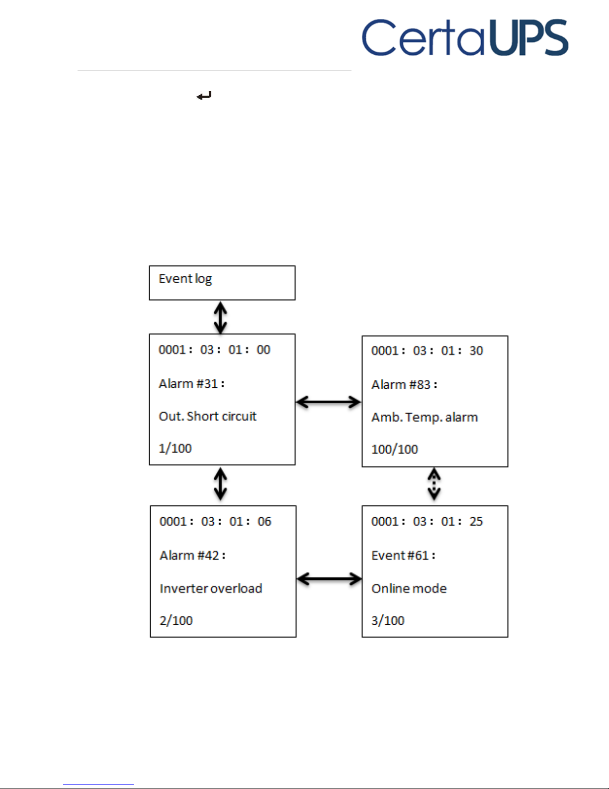
The event log menu
By pressing on the menu of “Event log” the display will enter the next event
menu tree.
All previous events, alarms and faults will have been recorded here. The
information includes the description, event code, and the precise time when the
event occurred. By press ▲ or ▼ for less than 3 seconds, all the events could be
displayed one by one.
The maximum number of recorded events is 100, when the number is larger than
100, the oldest event will be overwritten.
By pressing ESC for more than 3 seconds the display will return to the last main
menu tree.
Page 34
26
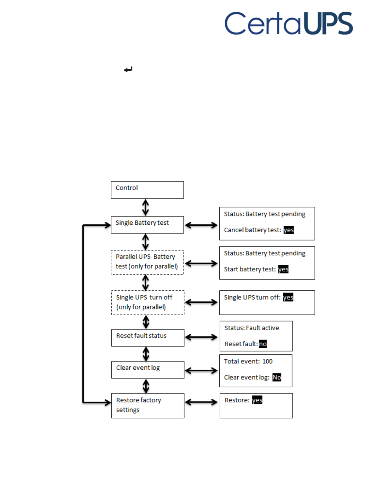
The control menu
By pressing on the menu of “Control”, the display would enter the next
control menu tree.
Start Battery Test: this is one command that commands the UPS to carry out a
battery self-test.
Reset Fault status: when a fault occurs, UPS will stay in Fault mode and alarm until
acknowledged. To clear the alarm, enter the “Reset Fault status” menu to reset
the error status, the UPS will cease alarming and return to bypass mode. The
cause of the fault should be established and cleared prior to the ups being
returned to normal operation
Restore factory settings: all the settings will be returned to their factory defaults.
This can only be done while in Bypass mode.
Page 35
27
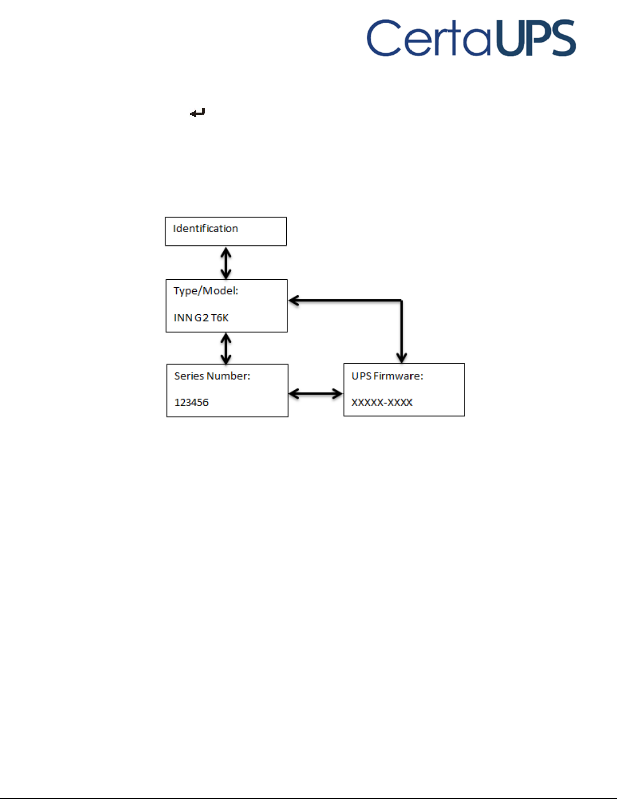
The identification menu
By press on the menu of “Identification” the display enters the next
identification menu tree.
The identification information includes UPS serial number, firmware version and
model.
By press ESC for more than 3 seconds the display will return the last main menu
tree.
Page 36
28
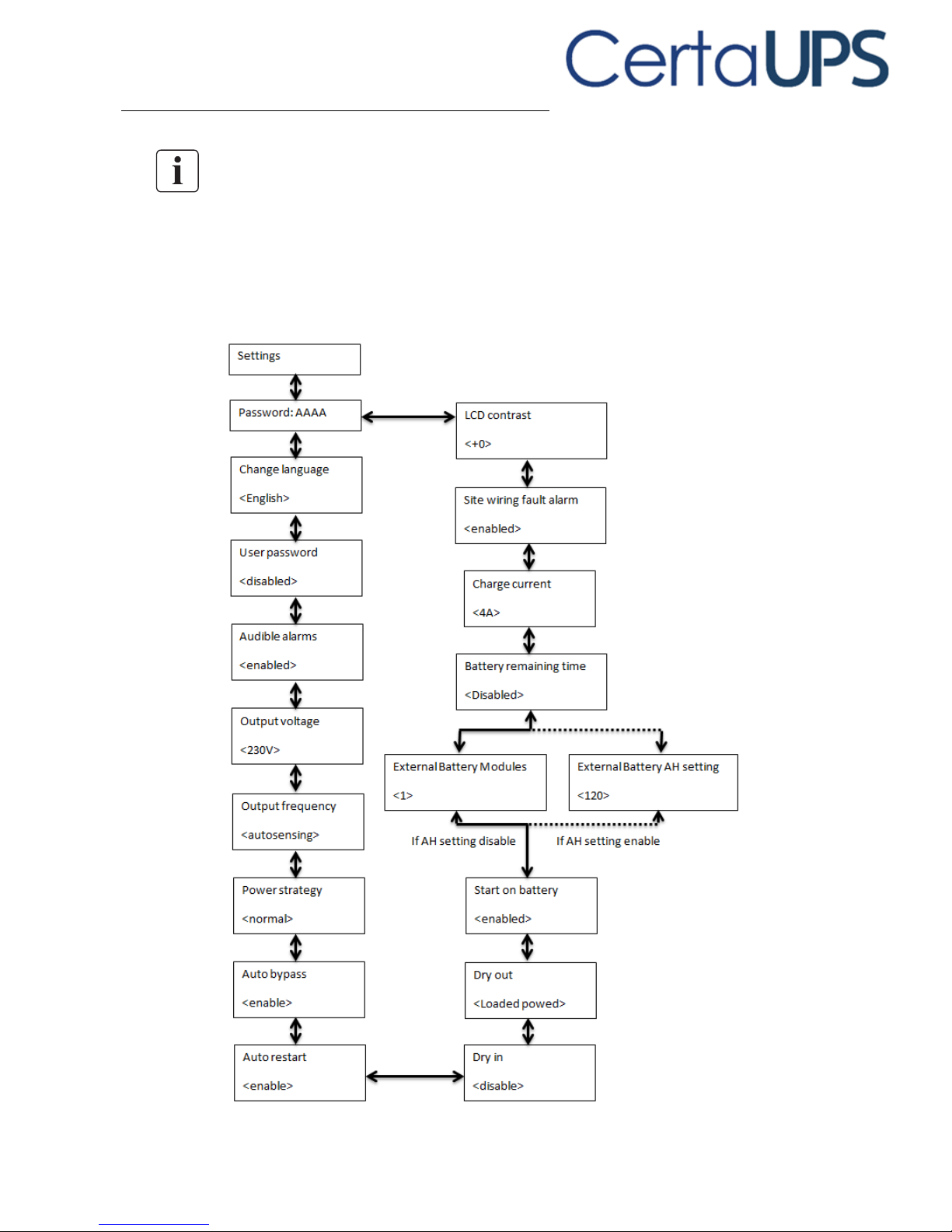
The setting menu
Please contact your local distributor for further information before using the
settings. Some settings would be changed the specification, and some settings
would enable or disable some functions. The unsuitable option setting by user may
result in potential failures or protecting function loss, even directly damage the
load, battery or UPS.
AH setting could be set via RS232 or USB communication. Default AH setting is
disable.
Most of settings could only be done while UPS is in Bypass mode.
Page 37
29
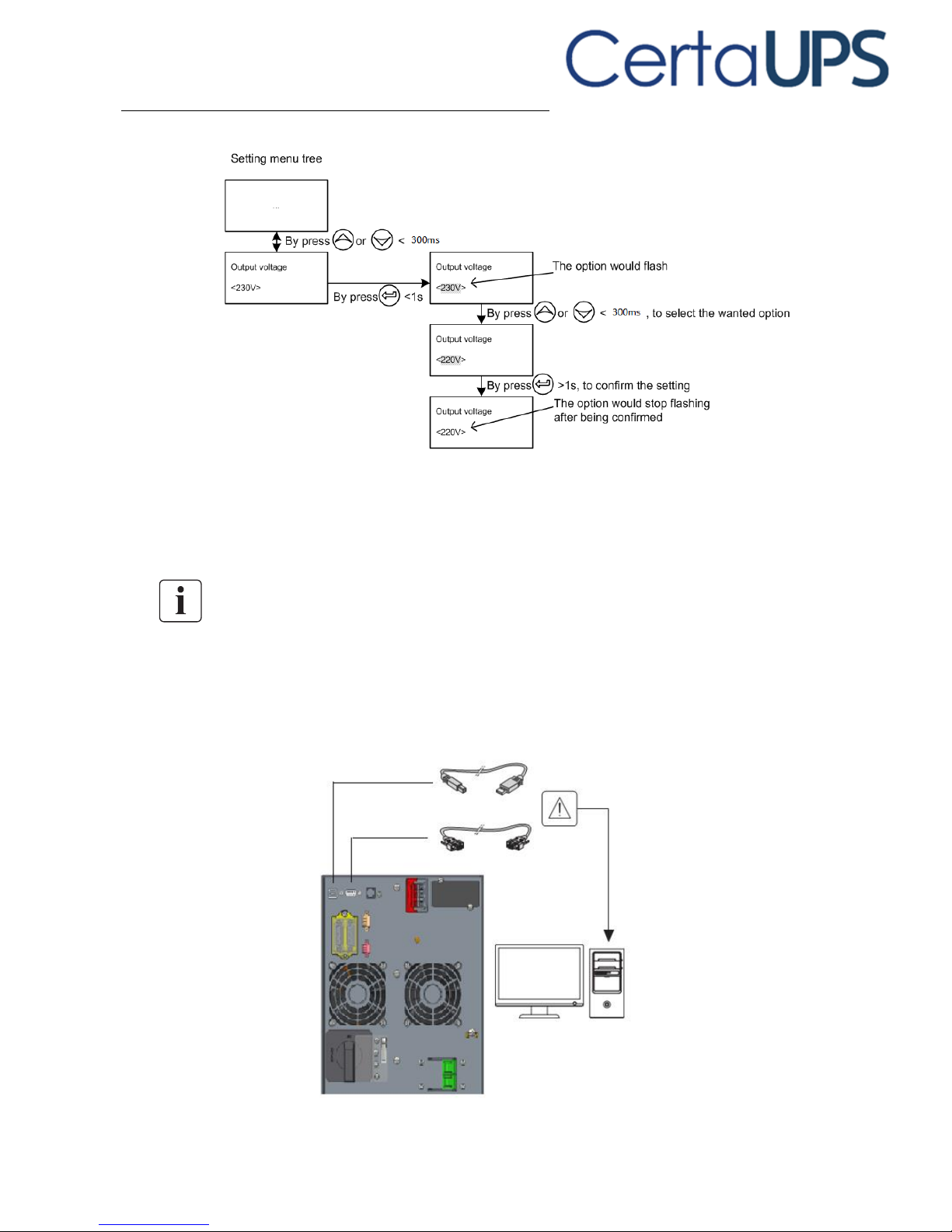
Example: set rated output voltage value
6. Communication
6.1 Communication ports
RS232 or USB communication ports
The RS232 and USB communication ports cannot be used simultaneously.
1. Connect the communication cable to the serial or USB port on the computer.
2. Connect the other end of the communication cable to the RS232 or USB
communication port on the UPS.
Page 38
30
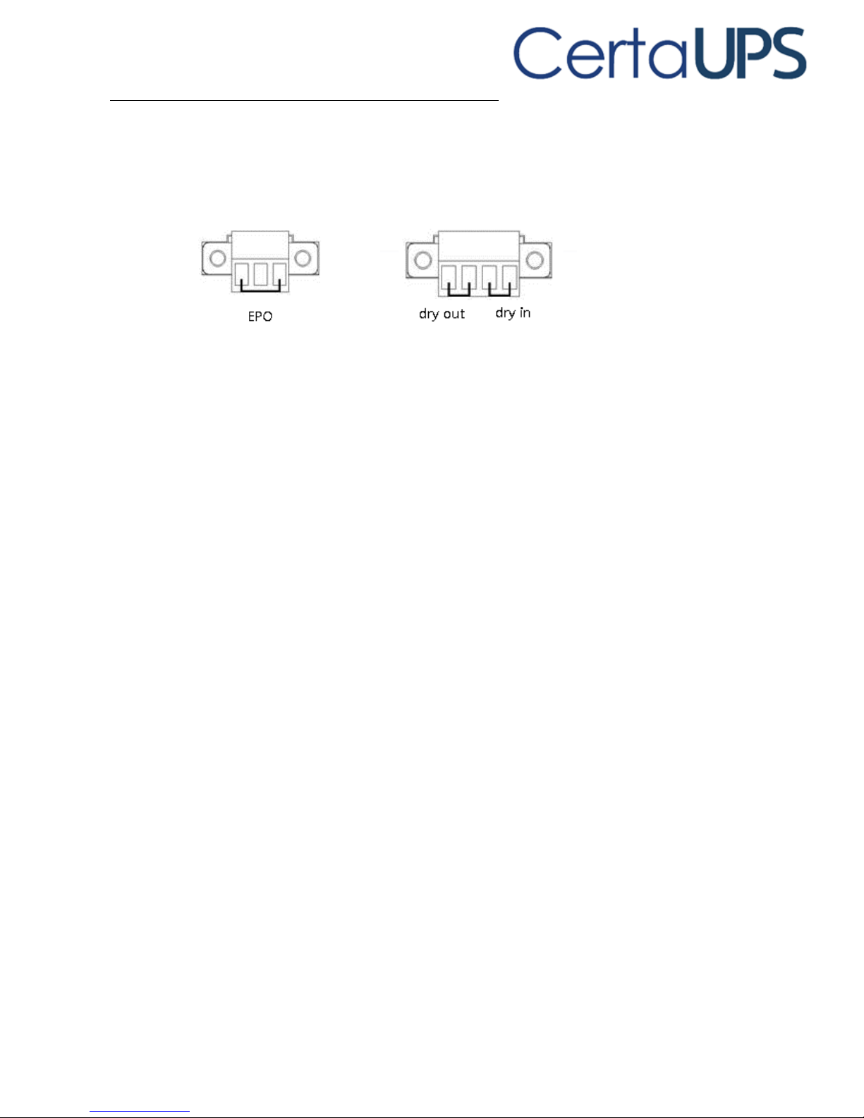
Emergency Power off (EPO)
The Emergence Power Off interface provides an emergence power off function.
When the EPO function is enabled (default setting the UPS will shut off the output
and enter into EPO mode when the plug is removed. The UPS will also be
unresponsive to all inputs until the EPO plug is reinserted into the UPS.
Dry in & Dry out
Dry in allows maintenance bypass to be remotely switched on and off. When the
contact changes the maintenance bypass is switched on or off depending on its
current state.
Dry out could indicate the status of UPS.
The Dry out port is normally closed, if the Dry out port is open it indicates an event
has occurred such as;
Output overload
On battery mode
Battery low
Battery disconnected
Bypass enabled
6.2 Network Management Card (Optional)
The Network Management Card allows the UPS to communicate with monitoring
devices by utilizing network connectivity. The Online series has one available
expansion bay for the following connectivity cards:
1. UPS-MS Web/SNMP Card – this interface card provides SNMP and HTTP
capabilities as well as monitoring through a Web browser interface using
RJ45 10/100Mbps over TCP/IP.
2. AS400 card for AS400 communication protocol. Please contact your local
distributor for details.
Page 39
31
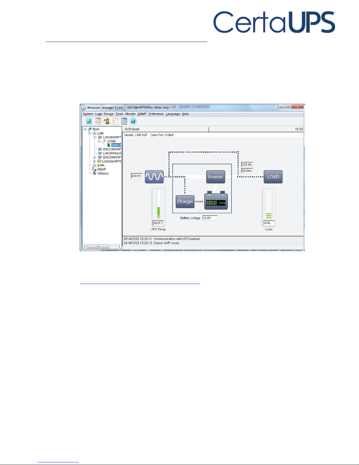
6.3 UPS Management Software
WinPower is software for UPS monitoring and management which provides a user
friendly interface as well as 2 way control of your UPS. This unique software
provides automatic shutdown functionality for multi computer systems when
power failure is detected. With this software users can monitor and control
multiple UPSs on the same network no matter the distance.
Installation procedure:
1. Go to the website:
http://www.ups-software-download.com/
2. Choose the operating system you need and follow the instruction described on
the website to download the software.
3. When downloading all required files from the internet, enter the product key:
511C1-01220-0100-478DF2A to install the software.
When the installation finishes restart your computer, the WinPower software will
appear as a green plug icon located in the system tray, near the clock.
Page 40

32
7. UPS maintenance
7.1 Equipment care
For the best preventive maintenance keep the area around the equipment clean
and free from dust. If the atmosphere is very dusty, clean the outside of the
system with a vacuum cleaner.
For maximum battery life keep the equipment at an ambient temperature of 25°C
(77°F).
The batteries are rated for a 3-5 year service life. The service life varies depending
on the frequency of usage and ambient temperature. Batteries used beyond
expected service life will often have severely reduced runtimes. Replace batteries
at least every 4 years to keep units running at peak efficiency and prevent failure.
7.2 Transporting the UPS
The internal UPS batteries MUST be disconnected before transport.
The following procedure should be performed or supervised by personnel
knowledgeable about batteries and the required precautions. Keep unauthorized
personnel away from batteries. If the UPS requires any type of transportation, the
batteries must be disconnected (but not removed) before the unit is transported:
1. Verify that the UPS is off and disconnected from mains power.
2. Place the UPS on a flat stable surface with the front of the cabinet facing you.
3. Remove the UPS front cover
4 .Disconnect the internal battery connectors
5. Replace the UPS front cover
7.3 Storing the equipment
If you store the equipment for a long period, recharge the battery every 6 months
by connecting the UPS to utility power. The EBM charge to 90% capacity in less
than 3 hours however it is recommended that the batteries charge for 48 hours
after long-term storage. Check the battery recharge date on the shipping carton
label if the date has passed and the batteries were never recharged do not use
them.
Page 41

33
7.4 Replacing batteries
DO NOT DISCONNECT the batteries while the UPS is in Battery mode.
Consider all warnings, cautions, and notes before replacing batteries.
Servicing should be performed by qualified service personnel
knowledgeable of batteries and required precautions. Keep unauthorized
personnel away from batteries.
Batteries can present a risk of electrical shock or burn from high short circuit
current. Observe the following precautions:
1. Remove watches, rings, or other metal objects,
2. Use tools with insulated handles,
3. Do not lay tools or metal parts on top of batteries,
4. Wear rubber gloves and boots.
When replacing batteries, replace with the same type and number of
batteries or battery packs. Contact your service representative to order new
batteries.
Batteries must be disposed of responsibly. Refer to your local regulations
for disposal requirements.
Never dispose of batteries in a fire. Batteries may explode when exposed to
flame.
Do not open or modify the battery or batteries in any way. Released
electrolyte is harmful to the skin and eyes and may be extremely toxic.
Determine if the battery is inadvertently grounded. If inadvertently
grounded, remove source from ground. Contact with any part of a grounded
battery can result in electrical shock.
The likelihood of shock can be reduced if grounds are removed during
installation and maintenance (applicable to equipment and remote battery
supplies not having a grounded supply circuit).
ELECTRIC ENERGY HAZARD. Do not attempt to alter any battery wiring or
connectors. Attempting to alter wiring can cause injury.
Disconnect charging source prior to connecting or disconnecting battery
terminals.
Page 42

34
Replacing the EBM (External battery module)
The EBM is heavy and requires a minimum of 2 people to lift in to racking.
For the Tower module, turn the MBS to bypass and switch off the input and then
replace the EBM(s).
For the rotation module, if a PDU is connected to the UPS, turn the MBS to bypass
and switch off the input, it is then safe to replace the EBM(s). If a PDU is not
connected to the UPS, turn off the UPS and then replace the EBM.
To replace the EBM(s):
1. Unplug the EBM power cable and battery detection cable from the UPS.
If additional EBM(s) are installed, unplug the EBM power cable from each EBM.
2. Replace the EBM(s). See "Recycling the used equipment" for proper disposal.
A small amount of arcing may occur when connecting an EBM to the UPS. This is
normal and will not cause shock. Insert the EBM cable into the UPS battery
connector quickly and firmly.
3. Plug the EBM cable(s) into the battery connector(s).
4. Verify that the EBM connections are tight and that adequate bend radius and
strain relief exist for each cable.
5. Connect the battery detection cable(s) to the connector of the UPS and of the
EBM(s).
To test new batteries:
1. Charge the batteries for 48 hours.
2. Press on the menu of “Control”.
3. Select Control
4. Select Single battery test
The UPS starts a battery test if
1. The batteries are fully charged
2. The UPS is in Normal mode with no active alarms
3. Bypass voltage is acceptable.
During the battery test, the UPS transfers to Battery mode and discharges the
batteries for 10 seconds. The front panel displays and the percentage of
the test completed.
Page 43
35
7.5Recycling the used equipment
Contact your local recycling or hazardous waste center for information on proper
disposal of the used equipment.
Do not dispose of the battery or batteries in a fire. Batteries may explode. Proper
disposal of batteries is required. Refer to your regulations for disposal
requirements.
Do not open or modify the battery or batteries. Released electrolyte is toxic and
harmful to the skin and eyes.
Do not discard the UPS or the UPS batteries in the general waste. This product
contains sealed lead acid batteries and must be disposed of responsibly. For more
information contact your local recycling center.
Do not discard of waste electrical or electronic equipment (WEEE) in the trash.
For proper disposal contact your local recycling center.
8. Troubleshooting
The C500® G2 is designed for durable, automatic operation and also to alert you
whenever potential operating problems occur. Usually the alarms shown by the
control panel do not mean that the output power is affected. Instead they are
preventive alarms intended to alert the user.
Events are silent status information that are recorded into the Event log.
Example = "AC freq in range".
Alarms are recorded into the Event log and displayed on the LCD status
screen with the logo blinking. Some alarms may be announced by a beep
every 1 second. Example = "Battery low".
Faults are announced by a continuous beep and red LED recorded into the
Event log. Example = Out. Short circuit.
Use the following troubleshooting chart to determine the UPS alarm condition.
Page 44

36
8.1 Typical alarms and faults
To check the Event log:
1. By pressing on the menu of “Event log”.
2. Scroll through the listed events or faults.
3. The following table describes typical conditions.
Conditions
Possible cause
Action
Battery mode
Battery (Orange) LED is
On.
1 beep every 4 seconds.
Code: E062
A utility failure has occurred
and the UPS is in Battery
mode.
The UPS is powering the
equipment with battery
power. Prepare your
equipment for shutdown.
Battery low
Battery (Orange) LED is
On.
1 beep every 1 second.
Code: A012
The UPS is in Battery mode
and the battery is running
low.
This warning is
approximate and the
actual time to shutdown
may vary significantly, this
depends on the UPS load
and number of Extended
Battery Modules (EBMs).
No battery
Fault (Red) LED is Flash
1 beep every 1 second
Code: A011
The batteries are
disconnected.
Verify that all batteries are
properly connected.
If the fault persists contact
your service
representative.
The UPS does not provide
the expected backup
time.
The batteries need charging
or service is required.
Apply utility power for 48
hours to charge the
batteries. If the condition
persists contact your
service representative.
Bypass mode
Bypass (Orange) LED is
on.
Code: E060
An overload or a fault has
occurred or a command has
been received putting the
UPS in Bypass mode
Equipment is powered but
not protected by the UPS.
Check for one of the
following alarms: over
temperature, overload or
UPS failure.
Page 45

37
Power overload
Fault (Red) LED is Flash
2 beeps every 1 second
Code: A041
Power requirements exceed
the UPS capacity
Remove some of the
equipment from the UPS.
The UPS will continue to
operate but may switch to
Bypass mode or shut down
if the load increases.
The alarm resets when the
output load is reduced.
UPS over temperature
Fault (Red) LED is On.
Beep continuous.
Code: F081
The UPS internal heat sink
temperature is too high or a
fan has failed.
At warning level the UPS
generates the alarm but
remains normal or battery
mode.
If the temperature rises
another 2°C the UPS transfers
to Bypass mode or Standby
mode.
Clear vents and remove
any heat sources. Allow
the UPS to cool and ensure
the airflow around the UPS
is not restricted then
restart the UPS.
If the condition continues
to persist contact your
service representative.
ON Maintenance Bypass
Bypass (Orange) LED is
on.
Code: A072
UPS was manually
commanded to switch to
bypass and will remain in
bypass until commanded out
of bypass
Check the maintain bypass
switch status
In HE Mode
Line (green) LED is on.
Code: E063
The UPS is on bypass while
operating on the High
efficiency setting.
The equipment transferred
to bypass utility power as a
normal function of High
Efficiency operation.
Battery mode is available
and your equipment is
protected.
Site Wiring Fault
Fault (Red) LED is flash
1 beep every 1 second
Code: A004
Site Fault detection is
supported on all models
anytime there is a Grounded
Neutral connection.
Alarm triggers when the
difference between ground
and neutral voltage is > 15v.
Site Fault detection should
be enabled by default. It
can still be enabled and
disabled from the LCD
settings menu.
Reconnect all input wires.
Page 46

38
Back feed
Fault (Red) LED is On.
Beep continuous.
Code: F093
UPS has a unexpected bypass
current on battery mode
Transfer to maintenance
bypass and call service.
Inv Overload Fault
Fault (Red) LED is On
Beep continuous.
Code: F042
UPS has transferred to bypass
or fault mode because of
overload in inverter mode
The UPS transfers to
Battery mode if supporting
the load.
Remove some of the
output load from the UPS
Bypass Overload Fault
Fault (Red) LED is On.
Beep continuous.
Code: F043
UPS has cut off the output
and transferred to fault mode
because of overload in bypass
mode or HE mode.
Remove some of the
output load from the UPS
Output Short Circuit
Fault (Red) LED is On.
Beep continuous.
Code: F031
Indicates that the UPS has
detected abnormally low
impedance placed on its
output and considers it a
short circuit
Remove all output loads.
Turn off the UPS.
Check UPS output for
possible short circuit.
Ensure short circuit is
removed before turning on
again.
Fan Failure
Fault (Red) LED is flash
1 beep every 1 second
Code: A085
Indicates that the fan could
not operate normally
Check fans of UPS
BUS Over Voltage
Fault (Red) LED is On.
Beep continuous.
Code: F021
Indicates that the UPS is
reporting a BUS over voltage
fault.
The UPS transfers to
Bypass mode if supporting
the load
BUS Under Voltage
Fault (Red) LED is On.
Beep continuous.
Code: F022
Indicates that the UPS is
reporting a BUS under
voltage fault.
The UPS transfers to
Bypass mode if supporting
the load
BUS Unbalance
Fault (Red) LED is On.
Beep continuous.
Code: F023
Indicates that the positive
BUS voltage and negative BUS
voltage are out of tolerance.
The UPS transfers to
Bypass mode if supporting
the load
Page 47

39
BUS Short
Fault (Red) LED is On.
Beep continuous.
Code: F024
Indicates that the BUS voltage
decreased out of tolerance
Contact your service
representative
BUS Softstart Fail
Fault (Red) LED is On.
Beep continuous.
Code: F025
Indicates that the BUS could
not soft start successfully
Contact your service
representative
Inv Over Voltage
Fault (Red) LED is On.
Beep continuous.
Code: F032
Indicates that the UPS
reported an inverter over
voltage fault
The UPS transfers to
Bypass mode if supporting
the load
Inv Under Voltage
Fault (Red) LED is On.
Beep continuous.
Code: F033
Indicates that the UPS get
inverter under voltage fault
The UPS transfers to
Bypass mode if supporting
the load
Inverter Softstart Fail
Fault (Red) LED is On.
Beep continuous.
Code: F034
Indicates that the inverter
could not soft start
successfully
Contact your service
representative
Charger Fail
Fault (Red) LED is flashing
1 beep every 1 second
Code: A015
Indicates that the UPS has
confirmed the charger has
failed
The UPS turns off the
charger until the next
power cycle. Contact your
service representative
Battery Over Voltage
Fault (Red) LED is On.
Beep continuous.
Code: F016
Indicates that the battery
voltage is too high
The UPS will turn off the
charger until the battery
voltage is normal
Negative power Fault
Fault (Red) LED is On.
Beep continuous.
Code: F0E1
In parallel configurations a
single UPS is reporting
negative fault.
Redundancy mode,the
faulty UPS triggers a
fault,all UPSs in parallel
configuration will generate
a fault code. Contact your
service representative
Page 48

40
Parallel cable loss
Fault (Red) LED is On.
Beep continuous.
Code: F0E2
In parallel configurations a
parallel cable disconnect
Reconnect the parallel
cable to clear the fault. If
issue persists contact your
service representative
Parallel system battery
status
Fault (Red) LED is flash
1 beep every 1 second
Code: A0E6
In parallel configurations a
UPS is reporting a fault with
batteries/EBM.
Check battery connections
Line input different
Fault (Red) LED is flash
1 beep every 1 second
Code: A0E7
Within parallel system,UPS1
inout ok,UPS2 input lost
Check the line input
Power strategy different
Fault (Red) LED is flash
1 beep every 1 second
Code: A0E9
Parallel system,UPS mode
not consistent through
configuration i.e. normal,
converter,HE are different
Check UPS OP mode, set
OP mode be the same
Rated power difference
Fault (Red) LED is flash
1 beep every 1 second
Code: A0EA
Power rating between
individual ups in parallel are
different
Ensure all power ratings
within the parallel are the
same
HE in parallel
Fault (Red) LED is flash
1 beep every 1 second
Code: A0EB
Within parallel systems one
or more UPS modes are set as
HE
HE not allow in parallel
configurations
8.2 Silencing the alarm
Press the ESC (Escape) button on the front panel display for 2 Seconds to silence
the alarm. Check the alarm condition and perform the applicable action to resolve
the condition. If an alarm status changes the alarm will need to be silenced again.
Page 49
41
9. Specifications
9.1 Model specifications
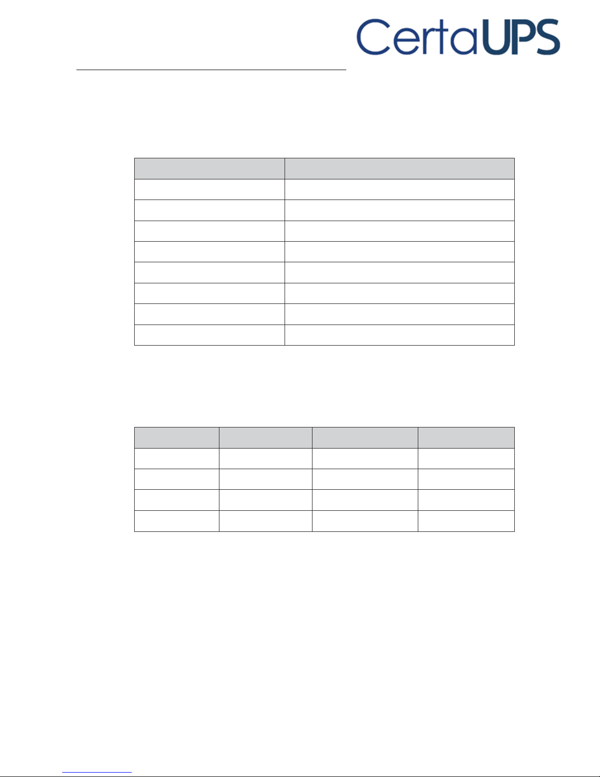
Table 1. Power Module model list
Model
Power Ratings
Tower standard 6K UPS
6000VA / 6000W
Tower standard 10K UPS
10000VA / 10000W
Tower long backup time 6KS UPS
6000VA / 6000W
Tower long backup time 10KS UPS
10000VA / 10000W
RT standard 6K UPS
6000VA / 6000W
RT standard 10K UPS
10000VA / 10000W
RT long backup time 6KS UPS
6000VA / 6000W
RT long backup time 10KS UPS
10000VA / 10000W
Table 2. Extended Battery Module model list
Model
Configuration
Battery voltage
For power ratings
Tower EBM
Tower
192Vdc
6000-10000VA
Tower EBM
Tower
240Vdc
6000-10000VA
RT EBM
RT
192Vdc
6000-10000VA
RT EBM
RT
240Vdc
6000-10000VA
Page 50
42
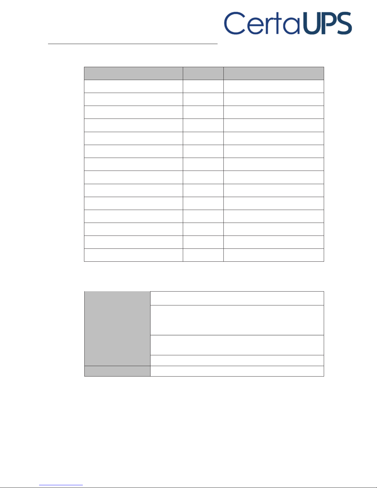
Table 3. Weights and dimensions
Description
Weights (kg)
Dimensions (mm) W x H x D
Tower standard 6K UPS 16PCS BAT
52.7
220*589*492
Tower standard 6K UPS 20PCS BAT
61.9
220*589*492
Tower standard 10K UPS 16PCS BAT
60.3
220*589*492
Tower standard 10K UPS 20PCS BAT
70.3
220*589*492
Tower long backup time 6KS UPS
13
220*348*492
Tower long backup time 10KS UPS
15.2
220*348*492
Tower EBM 16*2 BAT
84.6
220*589*487
Tower EBM 20*2 BAT
102
220*589*487
RT standard 6K UPS
13
438* 86.2* 573
RT standard 10K UPS
14.7
438* 86.2* 573
RT long backup time 6KS UPS
13.1
438* 86.2* 573
RT long backup time 10KS UPS
15
438* 86.2* 573
RT EBM 16 BAT
45.4
438*129* 593
RT EBM 20 BAT
54.6
438*129* 593
Table 4. Electrical input
Nominal frequency
50/60Hz auto-sensing
Frequency range
40 Hz– 70 Hz ≤60% rated load
45 Hz– 55 Hz(50Hz system)
54 Hz – 66 Hz (60Hz system) >60% rated load
45 Hz– 55 Hz
54 Hz – 66 Hz >60% rated load
Bypass voltage range
176~264Vac (default)
Noise filtering
MOV for normal and common mode noise
Page 51
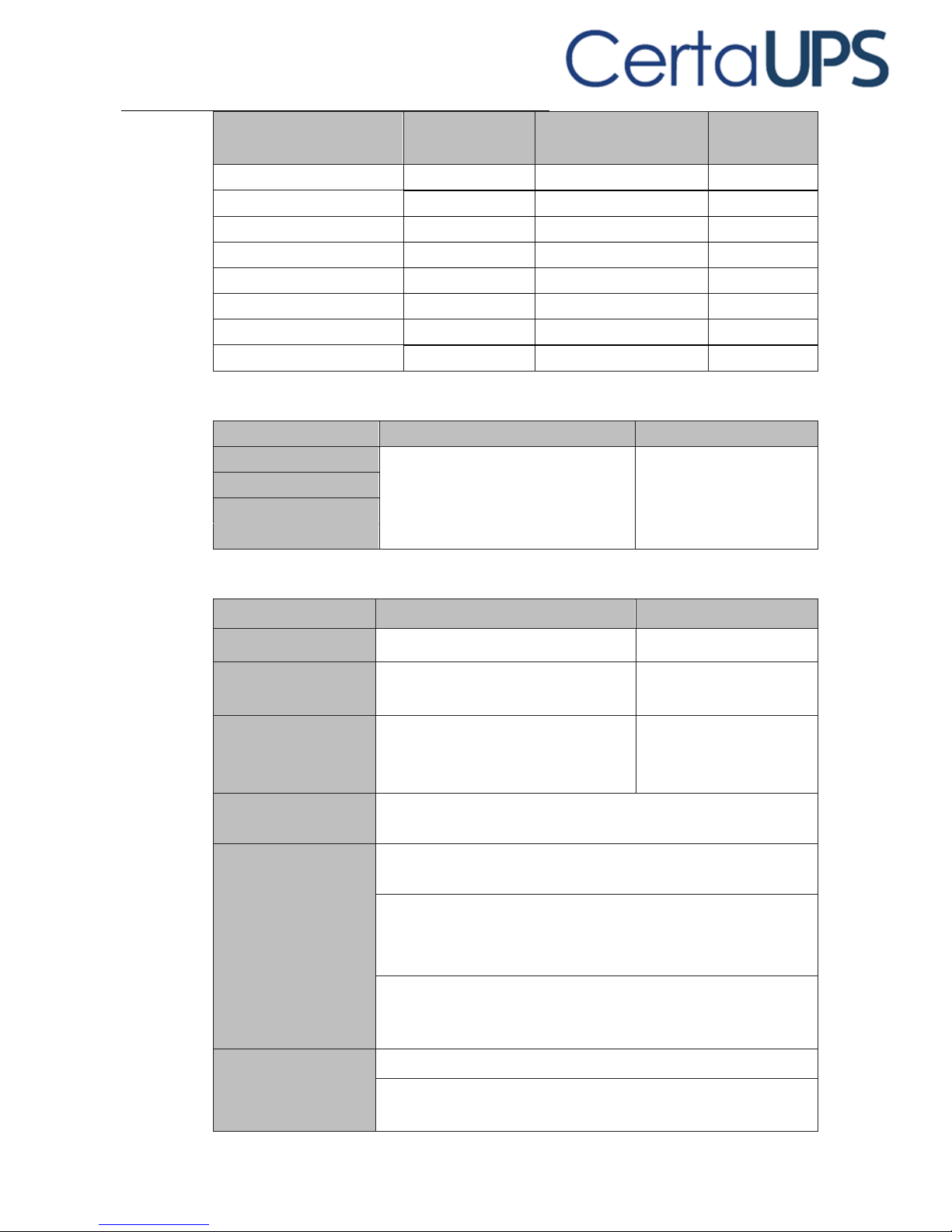
43
Model
Default input
(Voltage/Current)
Selectable input Voltage
range
Voltage
at 100% Load
Tower/RT 6K 16PCS BAT
230V / 31.2A
208/220/230/240V
176~275Vac
Tower/RT 6K 20PCS BAT
230V / 32.3A
208/220/230/240V
176~275Vac
Tower/RT 6KS 16PCS BAT
230V / 38.7A
208/220/230/240V
176~275Vac
Tower/RT 6KS 20PCS BAT
230V / 42.3A
208/220/230/240V
176~275Vac
Tower/RT 10K 16PCS BAT
230V / 49.9A
208/220/230/240V
176~275Vac
Tower/RT 10K 20PCS BAT
230V / 50.9A
208/220/230/240V
176~275Vac
Tower/RT 10KS 16PCS BAT
230V / 57.6A
208/220/230/240V
176~275Vac
Tower/RT 10KS 20PCS BAT
230V / 60.2A
208/220/230/240V
176~275Vac
Table 5. Electrical input connections
Model
Input connection
Input cable
Tower 6K/6KS
Hardwired
Not provided
RT 6K/6KS
Tower 10K/10KS
RT 10K/10KS
Table 6. Electrical output
All models
Normal mode
Battery mode
Voltage regulation
±1%
±1%
Efficiency
> 98% (High Efficiency mode)
> 95%
> 93%
Frequency regulation
Sync with line ±10% of nominal line
frequency (outside this range: ±0.1%
of auto-selected nominal frequency)
±0.1% of auto-selected
nominal frequency
Nominal output
208V*, 220V*, 230V, 240V, 250V* (voltage configurable)
6000/10000VA* 6000/10000W*
Frequency
50 or 60Hz, autosensing or configurable as a frequency
converter
Output overload
100-105% : no alarm
105-125% : load transfers to Bypass mode after 10 minutes
125-150% : load transfers to Bypass mode after 30s
Output overload
(Bypass mode)
100-105% : no alarm
105-125% : continue working and alarm
125-150% : UPS shuts down after 30 seconds
Voltage waveform
Sinewave
Harmonic distortion
< 1% THDV on linear load
< 5% THDV on non-linear load
Page 52

44
Transfer time
Online mode: 0 ms (no break)
High Efficiency mode: 10ms maximum (due to loss of utility)
Power factor
1
Load crest ratio
3 to 1
* 200/208/250V are derated at 10000VA 9000W, 220V is derated at 9900W for
11kVA models.
Table 7. Electrical output connections
Model
Output connection
Output cable
Tower 6K/6KS
Hardwired
Not provided
RT 6K/6KS
Tower 10K/10KS
RT 10K/10KS
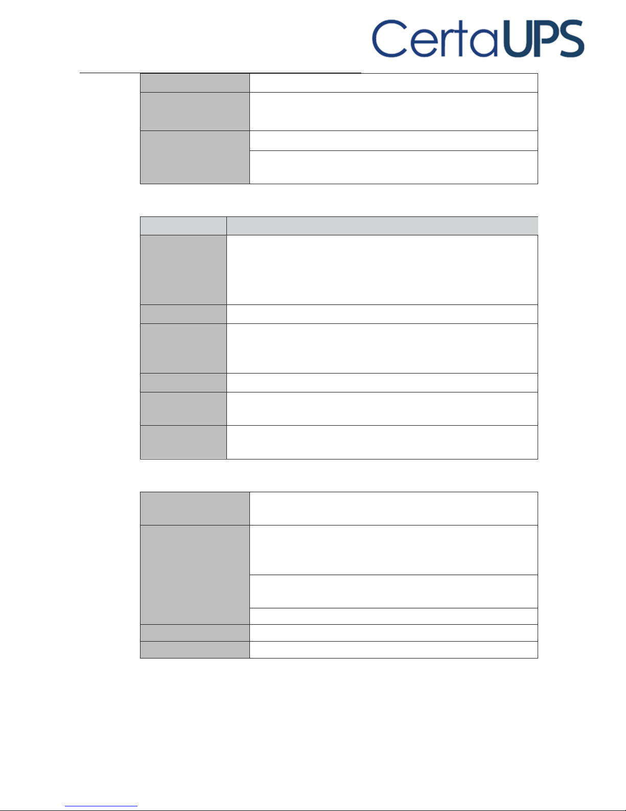
Table 8. Environmental and safety
EMC certifications
IEC/EN 62040-1
IEC/EN 62040-2
IEC/EN 62040-3
IEC 60950-1
EMC (Emissions)*
IEC 61000-3-2 (-3-12)
IEC 61000-3-3 (-3-11)
EMC (Immunity)
IEC 61000-2-2
IEC 61000-4-2, Level 4
IEC 61000-4-3, Level 3
IEC 61000-4-4, Level 4 (also on signal ports)
IEC 61000-4-5, Level 4, Criteria B
IEC 61000-4-6, Level 3
IEC 61000-4-8, Level 4
IEC 61000-4-11
* For output cable < 10m.
Agency markings
CE
Operating
temperature
0~40℃ full load no derating
40~50℃ output power derating to 50% load, Charger current
derating 50%
Storage temperature
-15 to 40°C (32 to 104°F) with batteries
-25 to 60°C (5 to 140°F) without batteries
Transit temperature
-25 to 55°C (-13 to 130°F)
Page 53
45
Relative humidity
0 to 95% no condensing
Operating altitude
Up to 3,000 meters (9,843 ft) above sea level with 10% derating
per 1000m
Transit altitude
Up to 10,000 meters (32,808 ft) above sea level
Audible noise
< 50 dBA at 1 meter typical for 6kVA models
< 55 dBA at 1 meter typical for 10kVA models
Table 9. Battery
EBMs
Rack / Tower
configuration
240Vdc 20 x 12V, 7Ah
240Vdc 20 x 12V, 9Ah
192Vdc 16 x 12V, 7Ah
192Vdc 16 x 12V, 9Ah
Fuses
100A for 10kVA models and EBM
Type
Sealed, maintenance-free, valve-regulated, lead-acid, with minimum
3-year float service life at 25°C (77°F). Lifetime is reduced above
30 °C.
Monitoring
Advanced monitoring for earlier failure detection and warnings.
Battery port
External ANEN-SA30 connector on power module for connection to
EBM
EBM battery cable
length
100cm for tower models
50cm for RT models
Table 10. Communication options
Communication bay
Available independent communication bay for connectivity
cards
Compatible
connectivity cards
MODBUS card
NMC card
AS400 card
Communication ports
RS-232 (DB9): 2400 bps
USB: 2400 bps
Dry out
2 pins jumper (normally closed)
Dry in
2 pins jumper (normally closed)
Emergency Power Off
3 pins jumper (normally closed)
Page 54

46
10 Glossary
Bypass AC source
Source supplying the bypass line. The equipment can be
transferred to the bypass line if an overload occurs on
the UPS output, for maintenance or in the event of a
malfunction.
Frequency converter
Operating mode used to convert the AC-power
frequency between the UPS input and output (50Hz ->
60Hz or 60Hz -> 50Hz).
Low-battery warning
This is a battery-voltage level indicating that battery
power is low and that the user must take action to
prevent the imminent loss to the supply of power to the
output load.
Backup time
Time during which the load can be supplied by the UPS
operating on battery power.
Load
Devices or equipment connected to the UPS output.
HE mode
Operating mode in which the load is supplied directly by
the AC source if it is within the tolerances defined by the
user. This mode reduces the consumption of electrical
power
Manual bypass
Rotary switch controlled by the user used to connect
the loads directly to the AC source. Transfer of the load
to the manual bypass enables UPS maintenance
without interrupting the supply of power to the
connected loads.
Normal (double
conversion) mode
The normal UPS operating mode in which the AC source
supplies the UPS which in turn supplies the connected
loads (after electronic double conversion).
Normal AC source
Normal source of power for the UPS.
Relay contacts
Contacts supplying information to the user in the form
of signals.
UPS
Uninterruptible Power Supply.
 Loading...