

Page 1
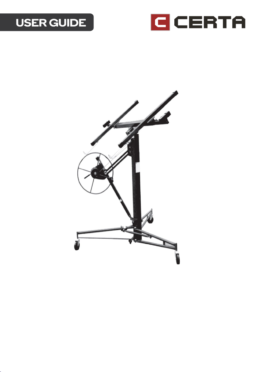
11’ DRYWALL GYPROCK PANEL LIFTER
CTPLFT11FTA
Page 2

Page 3

Important precautions
WARNING: To protect against serious injury, use common sense and observe the
following precautions when operating the drywall lift.
• Read and understand these instructions before operating and pay close attention
to all warnings.
• Always inspect the unit carefully before each use, paying special attention to the
condition of the cable.
• Always allow the lift to reach room temperature before use. Moving a cold unit into
a warm room can cause condensation, which could affect the operation of the
winch brake.
• Always be sure the brake drum is clean and dry before operating.
• Never use the lift if either cross-arm support is not secured by its locking spring tab.
• Always keep the work area free of obstructions.
• Always wear a hard hat when operating this lift.
• Always watch for overhead obstructions when lifting the drywall panel.
• Never use the lift for any purpose other than lifting a drywall panel.
• Never lift more than one sheet of drywall at a time. Never lift more than 68kgs.
Page 4

ASSEMBLY
• The drywall lift allows one person to lift a drywall panel that is up to 122 x 487cm in
size without assistance. The panel can be raised to a maximum height of 335cm
for attachment to level ceilings, or (with the lift's cradle tilted) to sloped ceilings or
sidewalls.
• The lift’s cradle lowers to 86.4cm off the floor for easy panel loading and can
support up to 68kgs.
Components
The drywall lift is shipped as several components that must be assembled before use:
• Tripod base assembly.
• Frame assembly, which includes a winch assembly and standard (122cm)
telescoping lift sections.
• Cradle assembly, without its detachable crossarms.
• Two cradle crossarm assemblies.
Page 5
Assembly Procedure
Press down on slide yoke ring
Set (lower) the Backstop
Crossarm
Cradle
Tripod Base
Frame Assembly
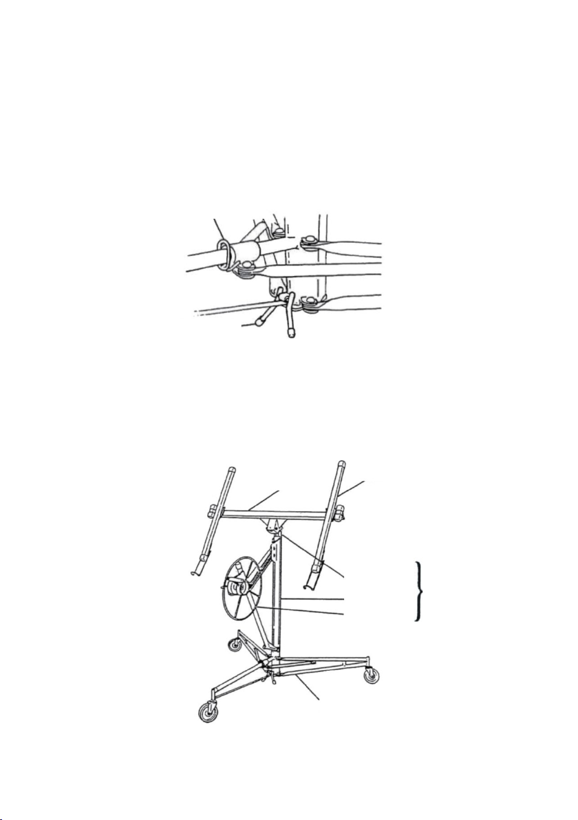
1. Set up the tripod base:
a. Set the base on the floor, resting on its casters.
b. Press down on the slide yoke ring. Hold the ring down while you swing the two
forward legs out until the yoke ring snaps back place into the locking hole on
the bottom of the slide tube (see Figure 1).
c. To prevent the tripod base from rolling backwards during assembly, lower the
backstop as shown.
2. Set the frame assembly onto the two “V” angles on the tripod base and lower the
frame about 1 inch. until it is secured by the angles.
Before continuing, be sure the frame is pushed down and is held securely by the
angles.
Telescoping
Sections
Housing
Winch
Components
Page 6
3. Attach the handle to the winch wheel. Tighten the nut and then back it off slightly
Rotate wheel
Raise brake
Grip break arm with your thumb
so the handle turns freely.
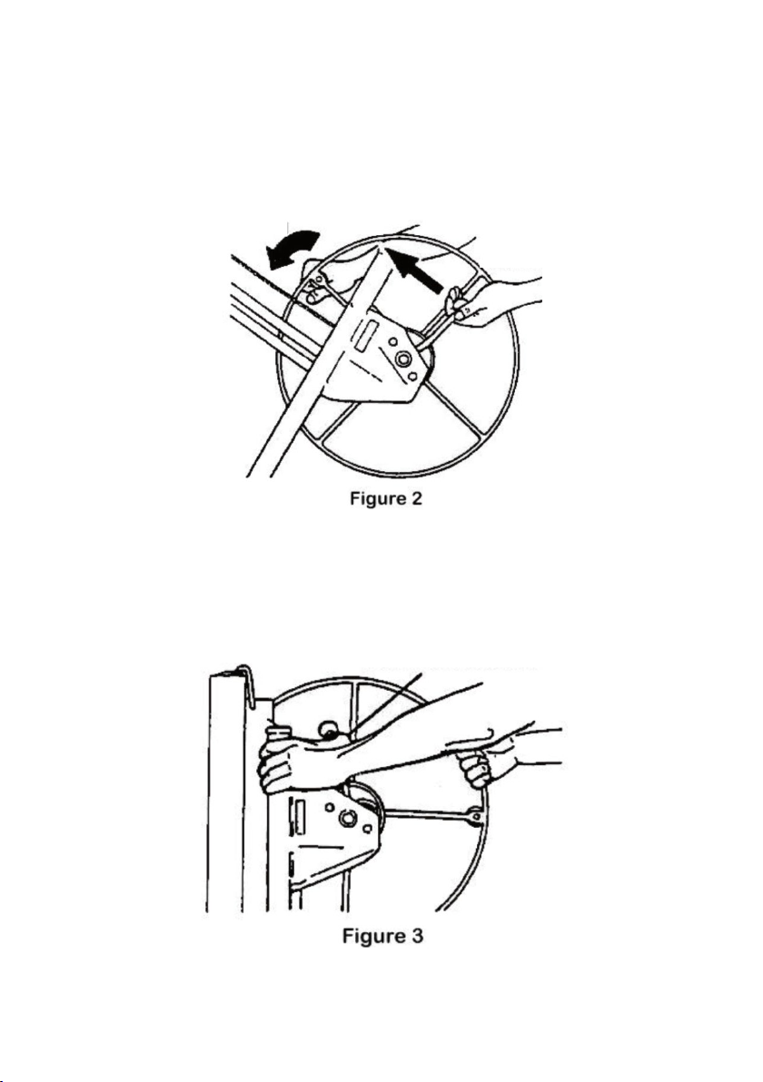
4. Move the winch assembly into its working position:
a. Hold the winch wheel and brake arm as shown in Figure 2. Rotate the
winch wheel forward slightly while you lift and release the brake arm.
forward
b. Raise the brake arm all the way up. Grasp the winch post and grip the
brake arm firmly with your thumb (Figure 3).
to prevent backlash
arm
Page 7
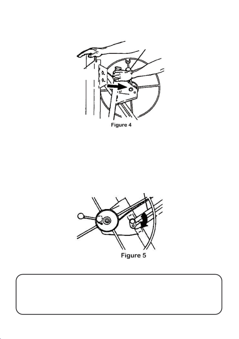
b. Place one hand on top of the frame. Continue to grip the brake arm to prevent
Continue to
Retaining
Slide bar
Rotate slide bar
extended.
cable backlash and pull the winch assembly toward you (see Figure 4 below).
grip break
arm
hook
c. When the winch is fully extended (away from the frame housing), release the brake
arm and swing the retaining hook away so it no longer secures the telescoping
sections inside the frame housing.
5. Press the winch assembly slightly back toward the frame. This automatically
engages the slide bar lock to keep the winch fully extended. (Figure 5)
WARNING: Before continuing, be sure that the slide bar lock is fully
engaged (rotated clockwise as far as possible).
To avoid injury, the slide bar lock must be fully engaged if winch assembly is
lock clockwise to
engage
Page 8
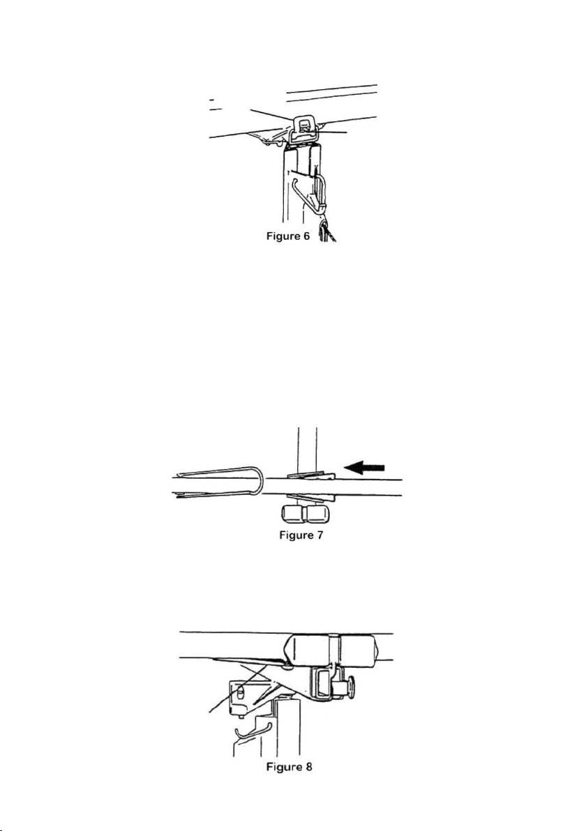
6. Attach the cradle to the frame (Figure 6).
Snap latch
Stud
Top View
Spring tab
upward
a. Insert the cradle’s post into the opening on top of the frame.
b. Secure the cradle to the frame by snapping the tilt latch upward so it
hooks over the stud on the cradle.
7. Attach the crossarms to the cradle (the crossarms are interchangeable):
a. Slide the tapered plates on the crossarms into the tapered sockets on the
cradle (Figure 7).
b. Press each crossarm forward into the socket until the spring tab on the
bottom of the crossarm snaps into place (Figure 8).
Page 9
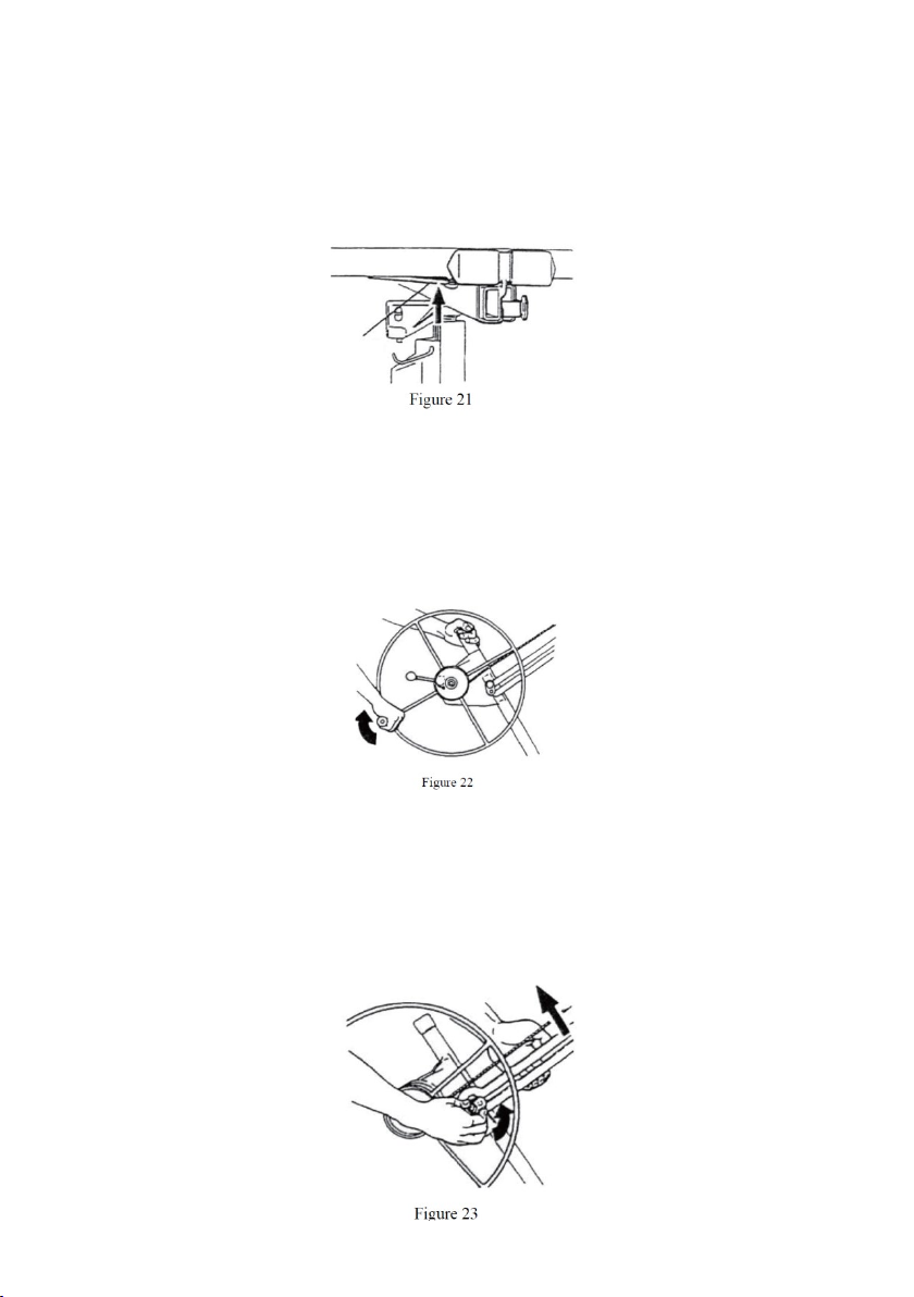
Disassembly
Press spring
To disassemble the drywall lift for transport or compact storage;
1. Crank the cradle down.
tab to
release
crossarm
2. Slide the cradle outriggers in until they latch. Close the panel support hooks.
3. Remove the crossarms by pressing the spring tab on the bottom and sliding the
crossarm out of the tapered socket.
4. Unlock the cradle tilt latch. Lift the cradle ~7cm until you can remove it from the
5. Rotate the winch wheel one full rotation forward as shown. This will raise the inner
frame.
telescoping section.
Page 10
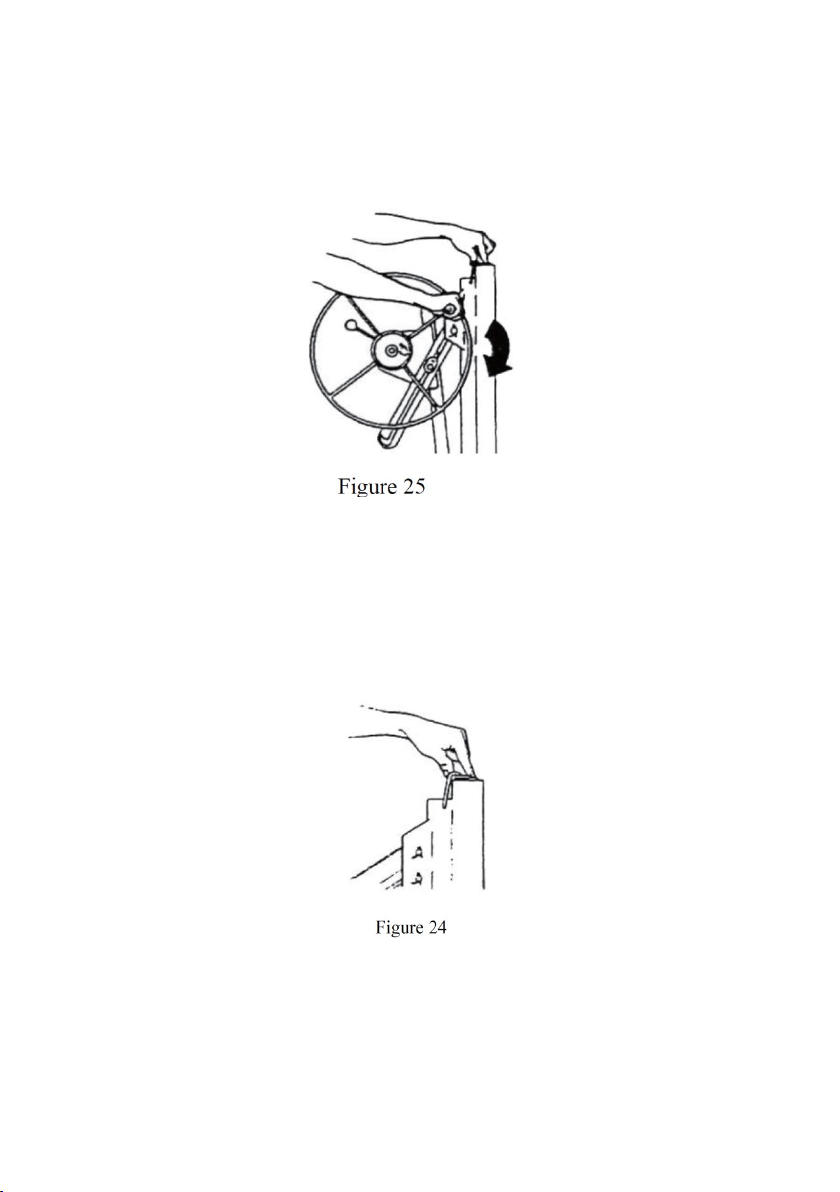
6. Unlock the winch assembly by lifting the slide bar with your left hand while you
rotate the slide bar lock counter-clockwise with your right hand.
7. Hold the slide bar lock in this disengaged position (step 6). Press down on the
telescoping sections in the frame with your left hand. The winch assembly will
move toward the frame housing.
8. Crank the telescoping sections down. Swing up the retaining hook as shown and
crank the telescoping sections back up slightly until secured by the hook.
9. Hold the retaining hook in this position with your left hand and rotate the winch
forward with your right hand. The winch assembly will fold up against the frame.
When the slide bar contacts the frame, tighten the cable by turning the wheel
further (just enough to hold the winch assembly in this position).
10. Carefully lift the frame/winch ~2.5cm to free it from the tripod base.
11. To fold the base, press down on the slide yoke ring and pivot the forward legs
inward until they lock in the closed position.
Page 11
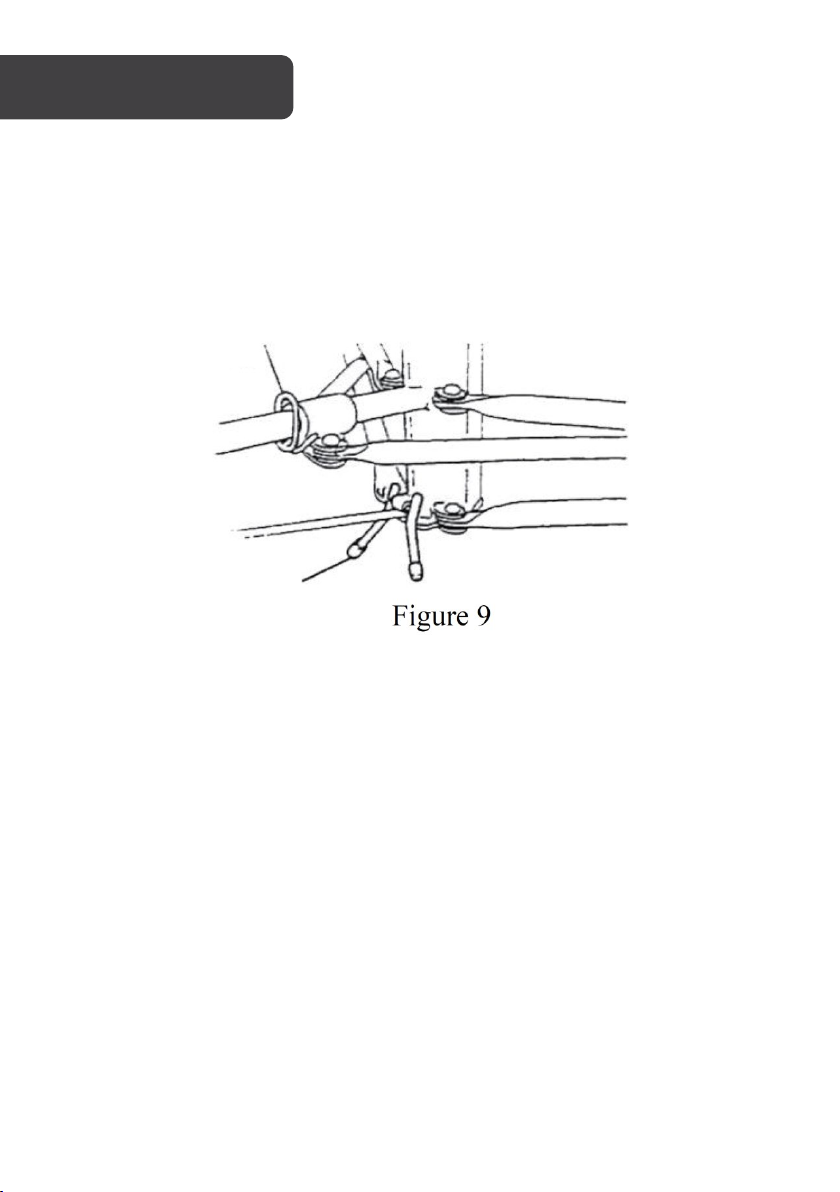
OPERATION
Backstop
Slide yoke ring
Slide yoke ring
Press down on the slide yoke ring to unlatch the two forward legs so they can be rotated out
to the lift’s working position or into its storage position. A spring-loaded pin snaps into a hole
on the bottom of the slide tube to lock the folding legs position.
Backstop
Pivot the backstop down to prevent the base from rolling backwards, or up to allow the unit
to wheel freely.
Page 12
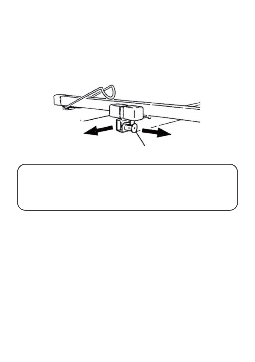
Outriggers
Outrigger
Lock pin
storing the lift.
The outriggers on the crossarms extend for supporting a longer drywall panel.
To extend an outrigger, pull out the lock pin with your right hand until you can slide the
outrigger out with your left hand.
The lock pin can engage to lock the outrigger at one of three positions: Fully retracted;
extended 53cm or extended 87cm. (see the mark)
WARNING: Never load a drywall panel or operate the Lift if the lock pins are not
engaged at one of these three positions, or if the outriggers are extended beyond the
56cm position.
To avoid damaging them, always fully retract the outriggers before transporting or
Page 13
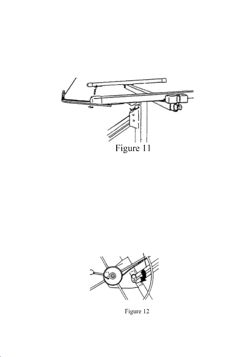
Panel support hooks
Panel support hook
Slide bar
Rotate
to engage
Open the support hook on each crossarm to support the drywall panel when it is being
loaded or when the cradle is tilted.
To avoid damaging them, always close the support hooks before transporting or storing the
lift.
Slide bar lock
The slide bar lock holds the winch assembly at its operating (fully extended) position.
To fold the winch assembly against the frame (when disassembling the unit for transport or
storage), disengage the lock by turning it counter-clockwise as you lift on the slide bar.
When you reassemble the unit for operation, extending the winch assembly all the way and
then pressing it back slightly toward the frame automatically engages the lock.
Never tighten the nut on the slide bar lock or you will be unable to fold up the unit for
transport and storage.
slide bar
lock
clockwise
Page 14
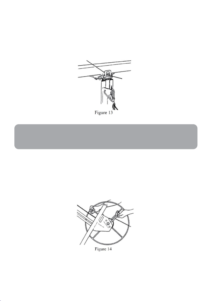
Tilt latch
Tilt latch
Stud
Break arm
Note:
To allow the cradle to tilt (for loading a drywall panel or raising the panel to a side wall or
sloped ceiling) or to remove the cradle from the frame, pivot the tilt latch out and down. To
lock the cradle onto the frame without tilting, pivot the latch up to engage the stud on the
cradle.
When it is in the level (non-tilted) position, the cradle will also tilt up to 10° side-to-side.
Brake arm
A spring-loaded brake holds the cradle at whatever height you raise it by cranking the winch
wheel. To lower the cradle, control the backward rotation of the winch by grasping the wheel
handle as you carefully raise the brake arm to release the brake.
Page 15
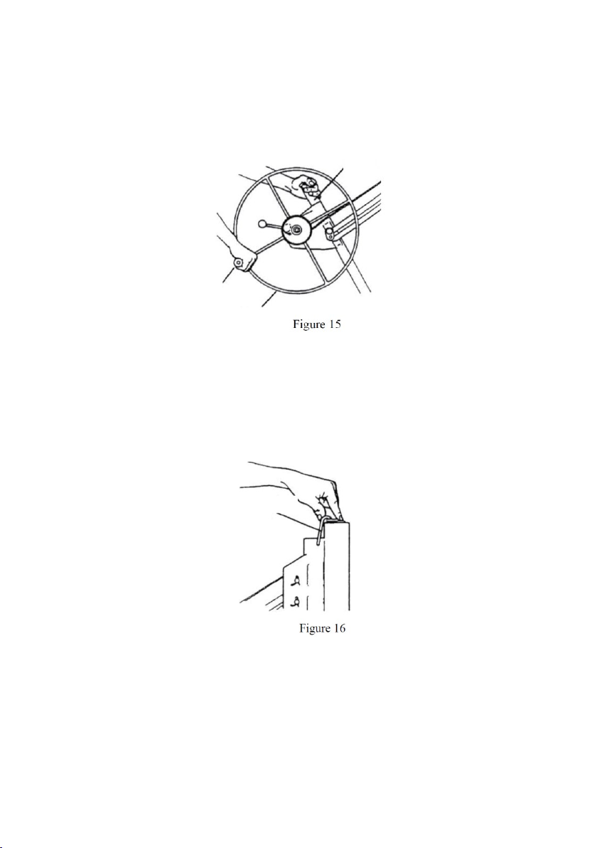
Winch wheel, handle, and post
Winch post
Wheel handle
Winch wheel
Retaining
hook
Cranking the winch (using the wheel handle) coils or uncoils the cable that raises or lowers
the cradle.
Grasp the post for leverage when cranking the winch.
Retaining hook
The retaining hook secures the telescoping sections inside the frame, for transport and
storage.
Page 16
Operating Procedure
WARNING: Ensure to thoroughly read and understand the “Important
WARNING:
Precautions” in “Safety & Warnings” above before operating the lift.
Safety check before operation
Before you begin operating the lift each time:
• Inspect the unit carefully for wear or damage. Pay special attention to the cable.
• Be sure the lift is at working room temperature before operating.
• Be sure the winch brake drum is clean and dry before operating.
• To avoid serious injury, follow all “Important Precautions”.
•
Always wear a hard hat when operating.
Use only for lifting drywall panels
•
•
Lift only one panel at a time.
•
Never lift more than 68kgs.
Page 17
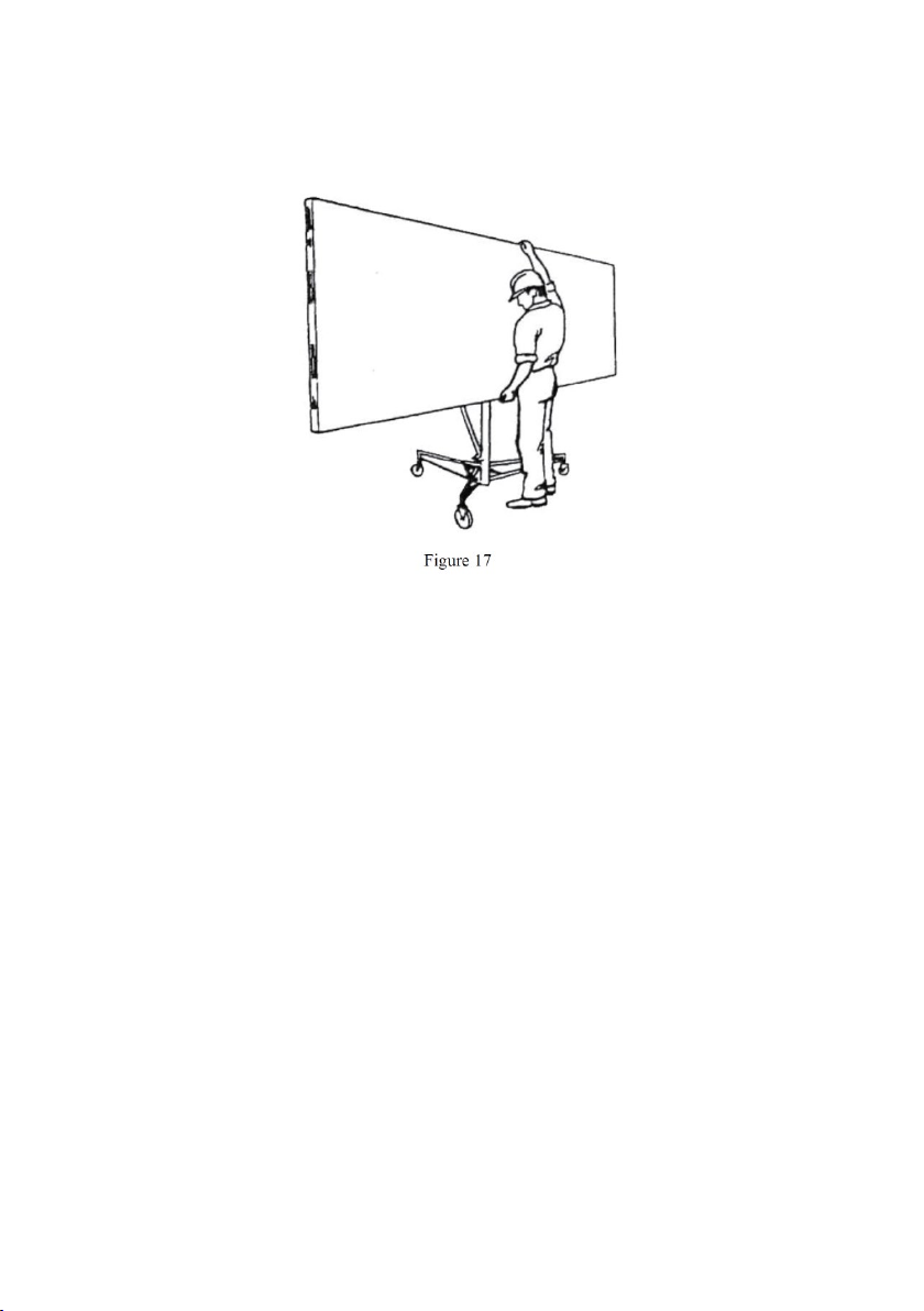
To load a drywall panel
1. Set (lower) the backstop so the lift will not roll backwards (see “Backstop” above).
2. Swing open the panel support hooks on the two crossarms. Be sure the cradle is
turned so the support hooks are on the opposite side from the winch wheel.
3. Extend the crossarm outriggers on the cradle as needed to fully support the length
of the drywall panel (see “Outriggers” above).
4. Release the tilt latch to tilt the cradle (see “Tilt Latch” above).
5. Hold the drywall panel with its face paper toward the tilted cradle and load the
panel onto the lift as shown. Set the panel onto the support hooks and carefully
lean it against the crossarms.
6. If installing the panel on a flat ceiling, tilt the cradle back up to its level position and
lock the tilt latch.
If installing the panel on a side wall or a sloped ceiling, leave the cradle tilted.
7. Raise the backstop on the base and carefully roll the lift close to the position where
the panel will be installed.
Page 18
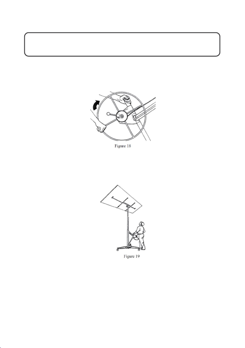
To raise the panel
WARNING: Always lower the backstop before raising the panel to a sloped
ceiling or a sidewall.
Crank the winch wheel in the direction shown (holding the post for leverage) until the panel
is at the desired height.
The brake is spring-loaded to automatically hold the cradle at the selected height when you
stop cranking.
Page 19
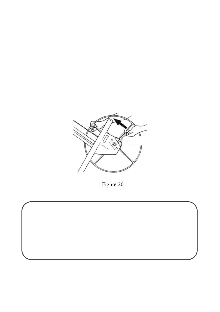
To lower the panel
Restrain the
Release the
brake carefully
1. Grasp the wheel handle with your right hand so you can restrain the backward
rotation of the winch.
2. Retain your hold on the winch handle. Carefully release the brake with your left
hand and slowly rotate the wheel back to lower the cradle to the desired height.
Disassembly and storage
Always store the lift in a dry protected area. To disassemble for more compact storage, refer
to “Disassembly” above.
backward rotation of
the winch
WARNING:
• To avoid serious injury, watch for overhead obstructions when raising
panels.
• The cradle drops rapidly when the brake arm is released.
• Control the winch with one hand on the wheel handle before
releasing the brake.
Page 20

CLEANING & CARE
Maintenance
• Inspect the cable before each usage. Replace it at the first sign of wear (refer to the
instructions supplied with the replacement cable).
• Occasionally oil the cable pulleys. Crank up the telescoping sections for access to
the internal cable pulley. Never allow oil or grease to contact the surface of the
winch brake drum.
• Occasionally oil the castor bearings.
• If the telescoping sections of the frame do not operate smoothly, apply household
paraffin to the sliding surfaces.
Page 21

Need more information?
We hope that this user guide has given you
the assistance needed for a simple set-up.
For the most up-to-date guide for your product,
as well as any additional assistance you may require,
head online to help.kogan.com
 Loading...