

Page 1
Claudo Sconce
Installation Instructions
General Product information
This product is suitable for indoor dry locations only.
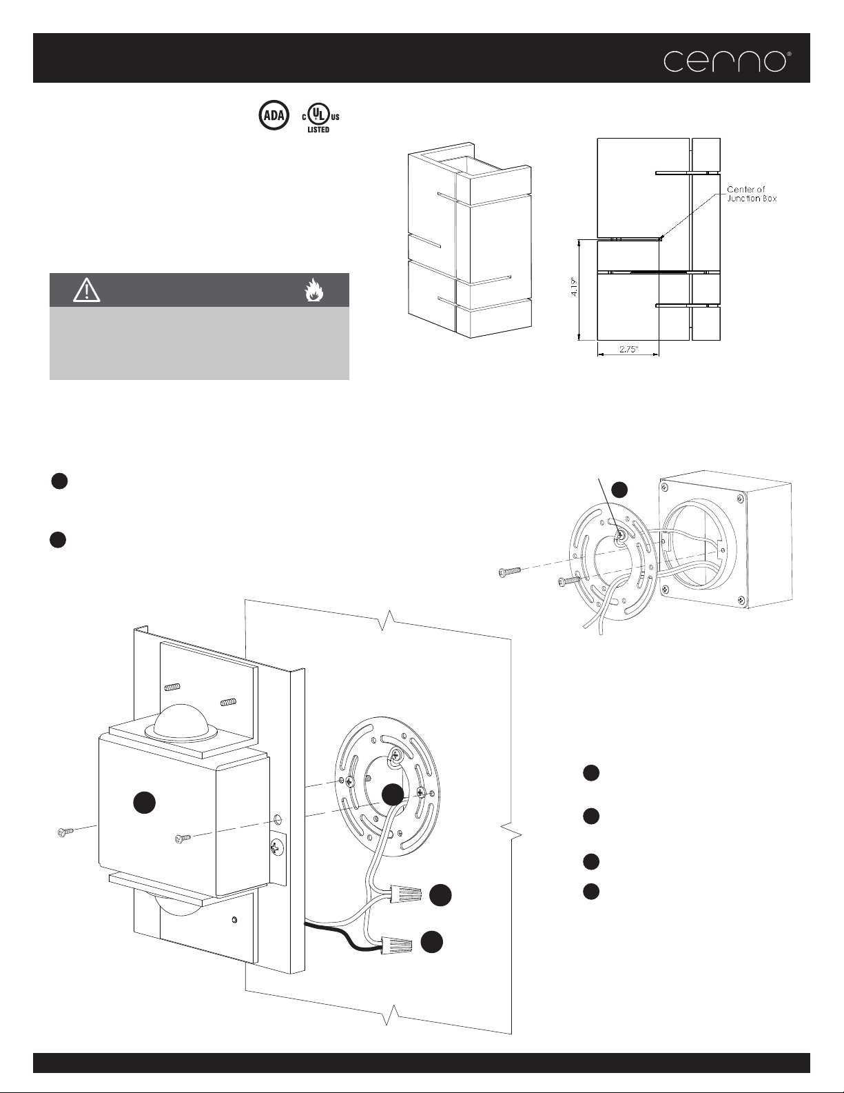
This product is to be installd to a standard 4” junction box
with 3” round plaster ring or an octagon junction box.
CAUTION - RISK OF FIRE
This product requires installation by a qualied
electrician. Before installing be sure to read
all instructions and TURN POWER OFF TO THE
JUNCTION BOX
Installing the Mounting Plate
Attach the mounting plate to the junction box using
1
the supplied #8-32 screws. Orient and level the plate
as shown in the gure.
Attach a suitable ground wire to the green screw in
2
the mounting plate.
Back Plate
6
8-32 Screw
Junction Box
Ground
2
Mounting Plate
8-32 Screw
Typical 3” Plaster Ring
Attaching the Back Plate
3
Connect the white xture wire to the
5
neutral power line with a wire nut.
4
Connect the black xture wire to the
hot power line with a wire nut.
5
White (NEUTRAL)
3
Place all wires in the junction box.
6
Mount the back plate to the mounting plate using the supplied #8-32
screws.
4
Black (HOT)
CERNOGROUP.COM T_949.715.1534 1751 MCGAW AVE, IRVINE, CA 92614 COPYRIGHT 2016 CERNO LLC. ISSUE DATE 2/5/2019
CERNOGROUP.COM T: 949.715.1534 22892 GLENWOOD DRIVE, ALISO VIEJO, CA COPYRIGHT 2021 CERNO LLC. ISSUE DATE 01/01/2021
Page 2
Claudo Sconce
Installation Instructions
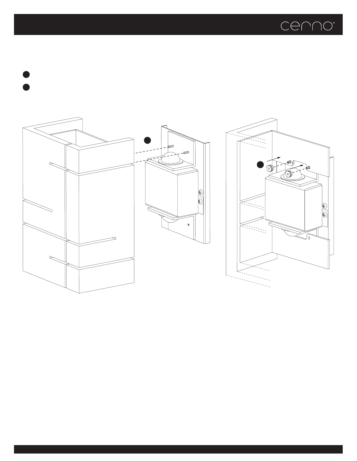
Attaching the Shade
7
Slide the shade onto the threaded screws protruding from the back plate.
8
Tighten the sconce shade against the light engine with provided thumb nuts.
7
8
(cut away view)
CERNOGROUP.COM T_949.715.1534 1751 MCGAW AVE, IRVINE, CA 92614 COPYRIGHT 2016 CERNO LLC. ISSUE DATE 2/5/2019
CERNOGROUP.COM T: 949.715.1534 22892 GLENWOOD DRIVE, ALISO VIEJO, CA COPYRIGHT 2021 CERNO LLC. ISSUE DATE 01/01/2021
Page 3
Claudo Sconce
Installation Instructions
Important Note!
This xture comes with a universal driver that can operate within an input voltage range of 120 and 277 V AC. See the table
below to understand which types of dimming are available for a particular input voltage.
Input Voltage Dimming Type
120 Triac, ELV, and 0-10V
240 0-10V only
277 0-10V only
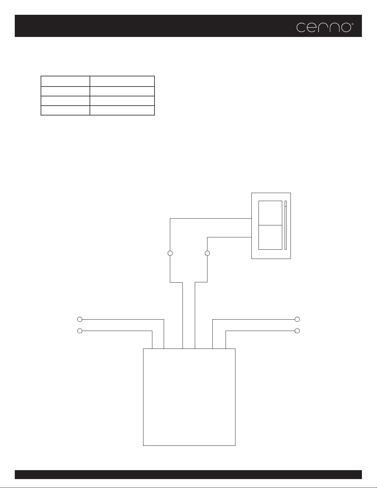
The purple and grey leads exiting from the LED driver are there to enable dimming of the xture through the use of a compatible 0-10V dimmer. If the xture is to be dimmed using a 0-10V dimmer, follow the wiring instructions provided with the
dimmer.
If the xture is NOT to be dimmed using a 0-10V dimmer, the tinned ends of these leads should be snipped o and the leads
should be capped individually such that they remain isolated from one another.
The wiring diagram below only applies if the
xture is to be controlled by a 0-10V dimmer.
Connect
to Line
Voltage
Source
0-10V
Dimming
Leads
Grey
Violet
AC Input Leads DC Output Leads
Included Class 2
LED Driver
Compatible
0-10V
Dimmer
Connect
to Fixture
Input
Leads
CERNOGROUP.COM T_949.715.1534 1751 MCGAW AVE, IRVINE, CA 92614 COPYRIGHT 2016 CERNO LLC. ISSUE DATE 2/5/2019
CERNOGROUP.COM T: 949.715.1534 22892 GLENWOOD DRIVE, ALISO VIEJO, CA COPYRIGHT 2021 CERNO LLC. ISSUE DATE 01/01/2021
 Loading...