


CERIO Corporation
DT-300N
2.4Ghz 300Mbps 11nbg 1000mW
High Power Wireless Router
User Manual

Table of Contents
1. Introduction ................................................................................................................................................... 5
1.1 Overview ...................................................................................................................................... 5
1.2 Package Content ......................................................................................................................... 6
1.3 Applications in Wireless Network ............................................................................................. 6
1.4 Features ..................................................................................................................................... 10
1.5 Panel Function Description...................................................................................................... 12
1.6 Hardware Installation Procedures ........................................................................................... 12
1.7 Software Configuration ............................................................................................................ 14
1.8 Wizard Setup ............................................................................................................................. 18
2. Router AP Mode Configuration ................................................................................................................. 23
2.1 Chose Your Operating Mode ( Router AP Mode ) .................................................................. 23
2.2 External Network Connection .................................................................................................. 23
2.3 Configure DDNS Setup ............................................................................................................. 28
2.4 Configure DT-300N LAN IP Address ....................................................................................... 29
2.5 Wireless General Setup ............................................................................................................ 31
2.6 Configure Wireless Advanced Setup ...................................................................................... 33
2.7 Create Virtual AP – Virtual AP Setup ...................................................................................... 38
2.8 Virtual AP General Configuration ............................................................................................ 38
2.9 WDS Setup - Expand your Wireless Network ......................................................................... 47
2.10 WDS Status ................................................................................................................................ 47
2.11 Associated Clients .................................................................................................................... 48
3. AP Mode Configuration .............................................................................................................................. 49
3.1 Chose Your Operating Mode ( AP Mode ) ............................................................................... 49
3.2 External Network Connection .................................................................................................. 49
3.3 Configure DT-300N LAN IP Address ....................................................................................... 50
3.4 Wireless General Setup ............................................................................................................ 51
3.5 Configure Wireless Advanced Setup ...................................................................................... 53
3.6 Create Virtual AP – Virtual AP Setup ...................................................................................... 58
3.8 WDS Setup - Expand your Wireless Network ......................................................................... 68
3.9 WDS Status ................................................................................................................................ 68
3.10 Associated Clients .................................................................................................................... 69
4. WDS Mode Configuration .......................................................................................................................... 69
4.1 Chose Your Operating Mode ( WDS Mode ) ........................................................................... 69
4.2 External Network Connection ( Network Requirement ) ....................................................... 70
4.3 Configure DT-300N LAN IP Address ....................................................................................... 70
4.4 Wireless General Settings ........................................................................................................ 73

4.5 Configure Wireless Advanced Setup ...................................................................................... 75
4.6 WDS Setup ................................................................................................................................. 80
4.7 WDS Status ................................................................................................................................ 81
5. Client Bridge + Repeater AP Mode Configura tion .................................................................................. 82
5.1 Chose Your Operating Mode(Client Bridge + Repeater AP) ................................................. 82
5.2 External Network Connection ( Network Requirement ) ....................................................... 82
5.3 Configure DT-300N LAN IP Address ....................................................................................... 83
5.4 Wireless General Setup ............................................................................................................ 85
5.5 Configure Wireless Advanced Setup ...................................................................................... 86
5.6 Site Survey ................................................................................................................................. 92
5.7 Station Profile ............................................................................................................................ 93
5.8 Remote AP Status ..................................................................................................................... 95
5.9 Repeater AP Setup .................................................................................................................... 96
5.10 Repeater AP MAC Filter Setup ............................................................................................... 100
6. WISP + AP Mode Configuration .............................................................................................................. 101
6.1 Chose Your Operating Mode ( WISP + Repeater AP Mode ) ............................................... 101
6.2 External Network Connection ( Network Requirement ) ..................................................... 101
6.3 Configure CPE(WAN) Setup ................................................................................................... 102
6.4 Configure DT-300N LAN IP Address ..................................................................................... 107
6.5 Configure DDNS Setup ........................................................................................................... 109
6.6 Wireless General Setup .......................................................................................................... 110
6.7 Configure Wireless Advanced Setup .................................................................................... 111
6.8 Site Survey ............................................................................................................................... 117
6.9 Station Profile .......................................................................................................................... 118
6.10 Remote AP Status ................................................................................................................... 120
6.11 Repeater AP Setup .................................................................................................................. 120
6.12 Repeater AP MAC Filter Setup ............................................................................................... 125
7. System Management ................................................................................................................................ 126
7.1 Configure Management .......................................................................................................... 126
7.2 Configure System Time .......................................................................................................... 129
7.3 Configure UPnP Setup ............................................................................................................ 130
7.4 Configure SNMP Setup ........................................................................................................... 130
8. Configure Advance Setup........................................................................................................................ 132
8.1 DMZ ........................................................................................................................................... 132
8.2 IP Filter ..................................................................................................................................... 133
8.3 MAC Filter ................................................................................................................................ 135
8.4 Virtual Server ........................................................................................................................... 136
8.5 Parental Control ...................................................................................................................... 138

8.6 QoS ........................................................................................................................................... 140
8.7 IP Routing ................................................................................................................................ 142
8.8 Time Policy .............................................................................................................................. 144
9. Configure Utilities Setup .......................................................................................................................... 145
9.1 Profile setting .......................................................................................................................... 145
9.2 Firmware Upgrade ................................................................................................................... 146
9.3 Network Utility ......................................................................................................................... 147
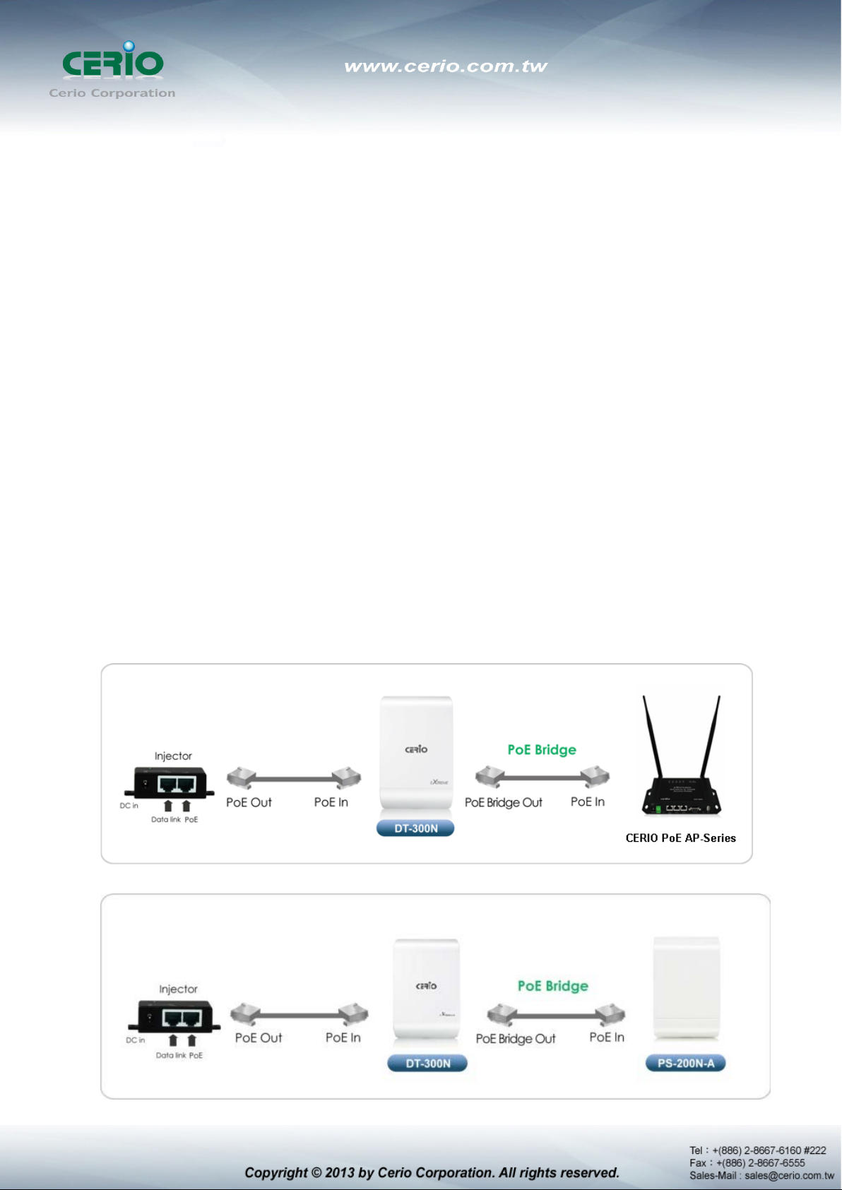
9.4 PoE Bridge ............................................................................................................................... 148
9.5 Reboot ...................................................................................................................................... 148
10. Configure Status .............................................................................................................................. 149
10.1 Overview .................................................................................................................................. 149
10.2 DHCP Client ............................................................................................................................. 150
10.3 Extra Info .................................................................................................................................. 150
10.4 Event Log ................................................................................................................................. 153
Appendix A. Windows TCP/IP Settings ...................................................................................................... 154
Appendix B. WEB GUI Valid Characters .................................................................................................... 156
Appendix C. MCS Data Rate ........................................................................................................................ 159
Appendix D. Enabling UPnP in Windows XP ............................................................................................. 160
Appendix E. Specifications .......................................................................................................................... 162
1. Introduction
1.1 Overview
DT-300N In/Outdoor Router AP Bridge utilizes a 1000mW high power with plastics housing
weatherproof and Built in 2.4 GHz 2x2 omni directional antennas. And Build in lightning
arrester (15kV ESD) DT-300N may connect to the WiFi mesh or WDS infrastructure and provides
the subscriber with an Ethernet connection for a local access .to extend the range and increase
the performance of our wireless network. The SOHO in/outdoor AP/bridge may connect to the
WiFi Mesh or WDS infrastructure and provides the subscriber with an Ethernet connection for a
local access. also with included PoE power and data are supplied to the unit using CAT5
Ethernet cable. Furthermore the DT-300N have support PoE power supply function, and Support
PoE Bridge, Can provide PoE Power to the next DT-300N PoE unit .
The CERIO DT-300N 2.4Ghz 300Mbps 11nbg 1000mW SOHO In/Outdoor Router AP/ AP Bridge
of connection to Wireless In/Outdoor Network for service provider deploying last mile services to
Home SOHO or business or residential broadband subs cribers. Netw ork administrators can create
multiple subscriber service tier using per-subscriber rate limiting features, and manage centrally.
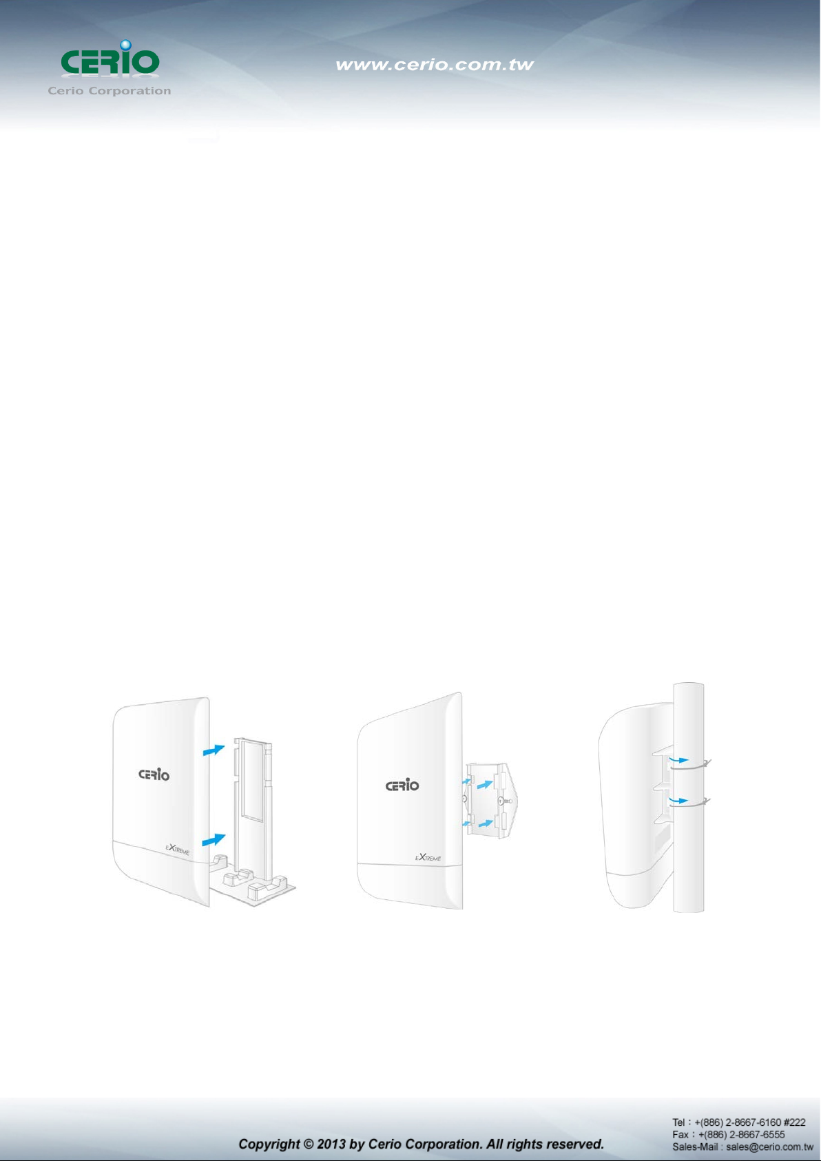
The DT-300N Structure (Form Factor ) Support Wall Mount, Pole Mount and desktop.
Plastics Housing with Weatherproof
.
Design the
Desktop Stand
Sample for desktop on blister inner stand
Wall mounting
Sample for mounting on wall
Pole mounting
Sample for mounting on bat
1.2 Package Content
DT-300N Main Unit x1
RJ-45 UTP Cable x1
Power Adapter (Power Supply) x1
PoE Adapter x1
Wall Mounting kit x1
Desktop Blister Stand x1
Self Locking Cable Ties for Stand or Pole Mounting x2
CD Manual x1
Quick Installation Guide x1
Warranty Card x1
1.3 Applications in Wireless Network
Smart of PoE Bridge applicati on
CERIO DT-300N 2.4Ghz 300Mbps 11nbg 1000mW Design smart PoE Bridge function, the PoE
Bridge function support provide next AP power. Can will be structure become very convenience.
And the PoE bridge support CERIO WM-series AP or OW-series to be dual band budle wireless
soultion.
CERIO DT-300N 2.4Ghz 300Mbps 11nbg 1000mW High Power SOHO In/Outdoor AP/ Bridge
supports six operational modes, the Router AP mode / Pure AP mode / AP+WDS mode / Pure
WDS mode / Client Bridge + Repeater AP Mode and WISP Repeater + AP mode etc.
respectively with built-in remote management features simplify the deployment and reduce cost
for continued maintenance of the outdoor bridge .
Wireless Architecture Mode
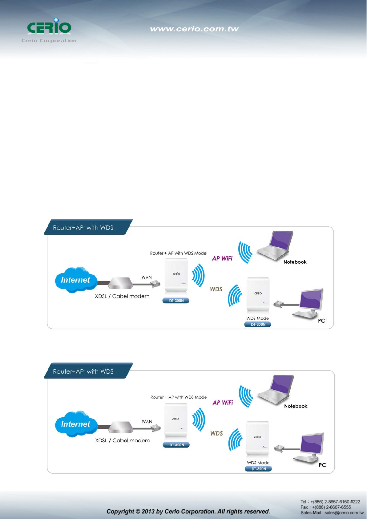
Router AP Mode (Gateway + Access Point + WDS)
Router AP without WDS , It can be deployed as a gateway with wireless Access Point
Router AP with WDS, It can be deployed as a gateway with wireless Access Point and
provides WDS link for network extension
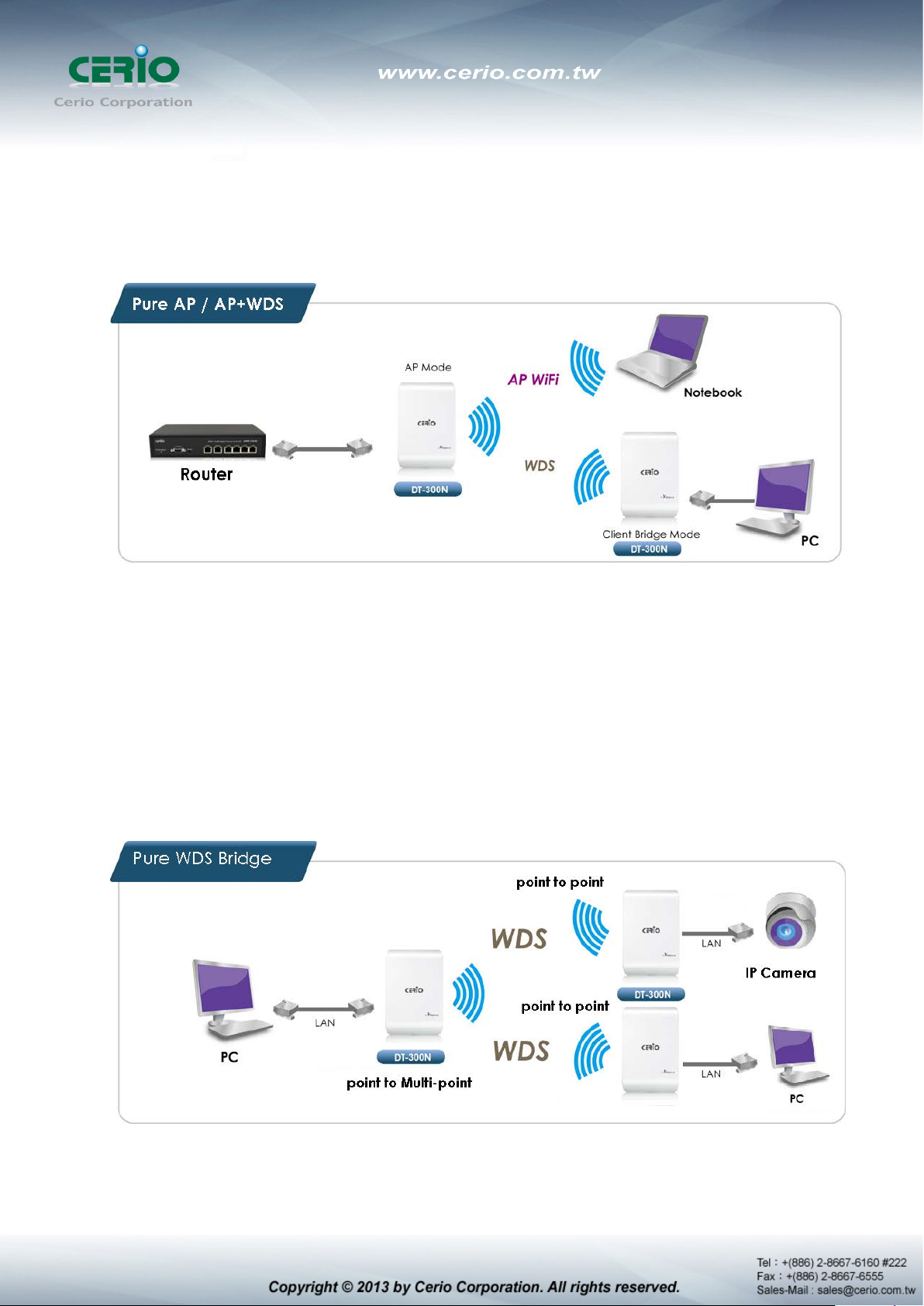
Pure AP Mode & AP/ AP+WDS Mode
It can be deployed as a tradition fixed wireless Access Point
It allow wireless clients or Stations(STA ) to access
This enables the wireless interconnection of Access Point in an IEEE802.11 network . and
accept wireless clients at the same time
Pure WDS Mode
This enables the wireless interconnection of Access Point in an IEEE802.11 network
It allows a wireless network to be expanded using multiple access point without the need for
a wired backbone to link them
This also be referred to as repeater mode It cannot allow wireless clients or Stations (STA)
to access
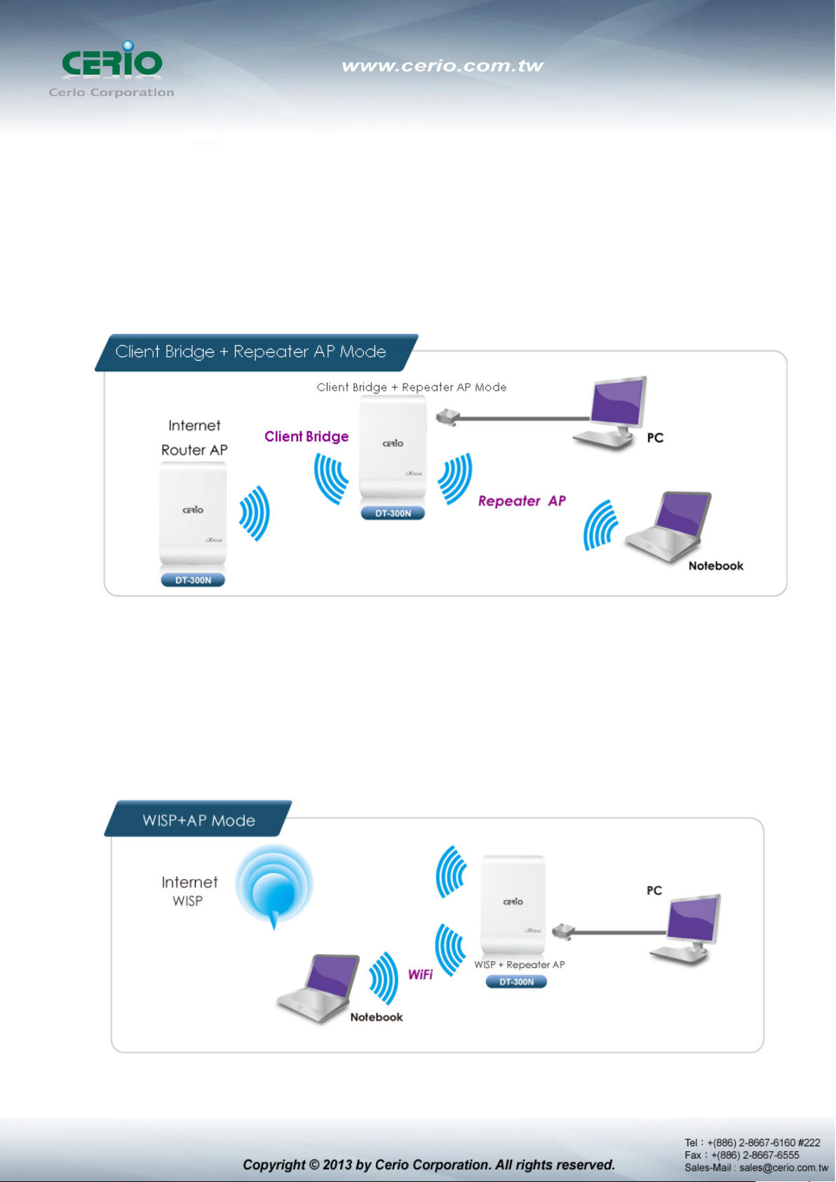
Client Bridge + Repeater AP Mode
It can be used as an Client Bridge + Repeater AP to receive wireless signal over last mile
applications, helping WISPs deliver wireless broadband Internet service to new residential
and business customers.
In this mode, DT-300N is enabled with DHCP Server functions. The wired clients of DT-300N
are in the same subnet from Main Base Station and it accepts wireless connections from
client devices, You can disabled the mode extend repeater AP function, will be do to “AP
Client ” function.
WISP + Repeater AP Mode
It can be used as an Outdoor Customer Premises E quipment (CPE ) to rec eive wireless signal
over last mile application, helping WISPs deliver wireless broadband Internet service to
residents and business customers
In the CPE mode, DT-300N is a gateway enabled with NAT and DHCP Server functions. The
wired clients connected to DT-300N are in different subnet from those connected to Main
Base Station, and, in CPE mode, it does not accept wireless association from wireless clients.

1.4 Features
Operation Modes : Router AP Mode, AP Mode, W DS Mode, AP+WDS Mode, Client Bridge +
Repeater AP Mode and WISP Repeater + AP Mode
1000mW at 2.4Ghz Output High Power
IEEE 802.11n 2Tx / 2Rx Design, Bandwidth of up to 300Mbps(Tx), 300Mbps(Rx) link rate
Maxmum Security with 802.1X, WAP, and WPA2
Support Over load current protection for the board design . and 3 LEDs Wireless Signal
Strength
Weater-Proof RJ45 Connector, Integragted Power over Ethernet (PoE)
Support PoE Bridge by LAN Port funtion.
Build in lightning arrester (15kV ESD)
Support 8 Multiple-BSSID. And Support IEEE802.11f IAPP
Support Static Routing and RIP and OSPF Dynamic Routing
Support Layer-7 Protocol Filter and Content Filter
QoS(Quality of Service) for bandwidth management and traffic prioritization
Support IEEE802.1d Spanning Tree
Waterproof IPX6 EN60529/IEC529 stand.
Integragted IGMP v1/v2/v3 snooping functions and Support Web management and SNMP
MIB-II
Built-in software interface allows for communicating with CERIO AM-Series AP Management
WLAN Switch or Access Controller of network management servers.
Networking
Support Static IP, Dynamic IP(DHCP Client) and PPPoE on WiFi WAN Connection
Support VPN Pass Throughput ( PPTP , IPSec , L2TP ) and MAC Cloning
Proxy DNS ,Dynamic DNS ,NTP Client
Virtual DMZ, Virtual Server (IP / Port Forwarding) and
Support IP / MAC Filter and Support Bandwidth trafic Shaping
Wireless Feature
Transmission power control : Layer 1~9
Channel selection : Manual or Auto
No of associated clients per AP : 32
Setting for max no associated clients : Yes
Support 8 virtual BSSID and associated clients per AP to 32 and the Pure WDS Max. 8
Setting for transmission speed
Dynamic Wireless re-transmission
IEEE 802.11i Preauth (PMKSA Cache )
IEEE 802.11h - TPC(Transmission Power Control)

IEEE 802.11d -Multi country roaming
Channel Bandwidth setting : 20MHz or 20/40MHz
HT Tx/Rx Stream selection : 1 or 2
Short Slot support
Authentication/Encryption (Wireless Security)
Blocks client to client discovery within a specified VLAN
WEP 64/128 bit /EAP-TLS + Dynamic WEP , EAP-TTLS + Dynamic WEP
PEAP/MSPEAP + Dynamic WEP
WPA-PSK/TKIP,WPA-802.1x/TKIP, 802.11i WPA2-PSK/CCMP/AES 128/256bit,
WPA2 (802.1x /CCMP / AES 128/256bit ), No. of registered RADIUS servers : 1
Setting for TKIP/CCMP/AES 128/256bit (ASCII 63 & HEX 64 )key’s refreshing period
Hidden SSID broadcast support, and VLAN assignment on BSSID
Access Control list (ACL) by MAC Address
Quality of Service
Download and Upload traffic control and support Traffic Analysis and Statistics
Packet classifications via DSCP (Differentiated Services Code Point) and Support
IEEE802.11e WMM
Control Policy by IP/IP Ranges/ MAC/ Service , Layer-7 Protocol Support
No. of Max. Policy setting : 10
DiffServ/TOS , IEEE 802.11p/COS, IEEE 802.1Q Tag VLAN priority control
Parental Control
Blocking Control Policy by IP Range / MAC Group / Port / Layer-7 Protocol
URL Block ing
Management
Web-Based management interface, Intuitive Web Management Interface,
Administrative Access : HTTP and HTTPS and support CLI access via Telnet and SSH
Support Firmware Upgrade via Web , Reset to Factory Defaults,
Support SNMP v1/v2c/v3 , MIB II
UPnP (Universal Plug and Play)
NTP Time Synchronization
SNMP Traps to a List of IP Address
Support Event log
1 2 3 4 5 6 7
8
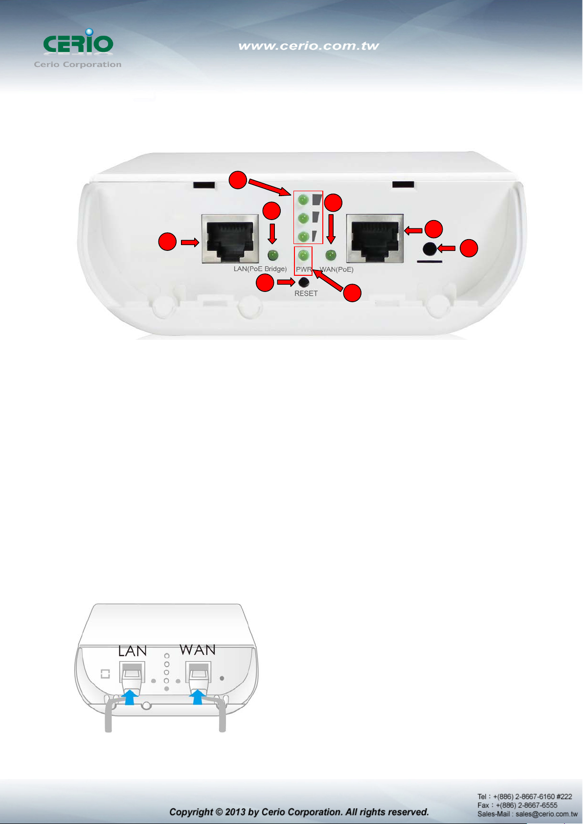
1.5 Panel Function Description
There is several LED indicators on the front of the DT-300N. Please refer to the definitions below :
(1) The Ethernet connect of LAN Port
(2) The LED indicator of LAN Port
(3) Reset button
(4) The Ethernet connect of WAN / PoE Port
(5) The LED indicator of WAN Port
(6) Power LED
(7) Ground connection
(8) The three LED’s for strong or weakly indicator on signal bridge, and the three LED’s only
support “Client Bridge + Repeater AP and WISP + Repeater AP modes”.
1.6 Hardware Installation Procedures
Please follow the instructors as below to finish the hardware installation.
1) LAN Port for PC, WAN Port for PoE adapter.

2) Grounding coble con be protect DT-300N from lightning strikes and buildup of static
electricity. Grounding cable not included in the package. Suggested that you use 16 to
18 AWG grounding cable.
3) Please install the cover.
4) For xDSL user’s
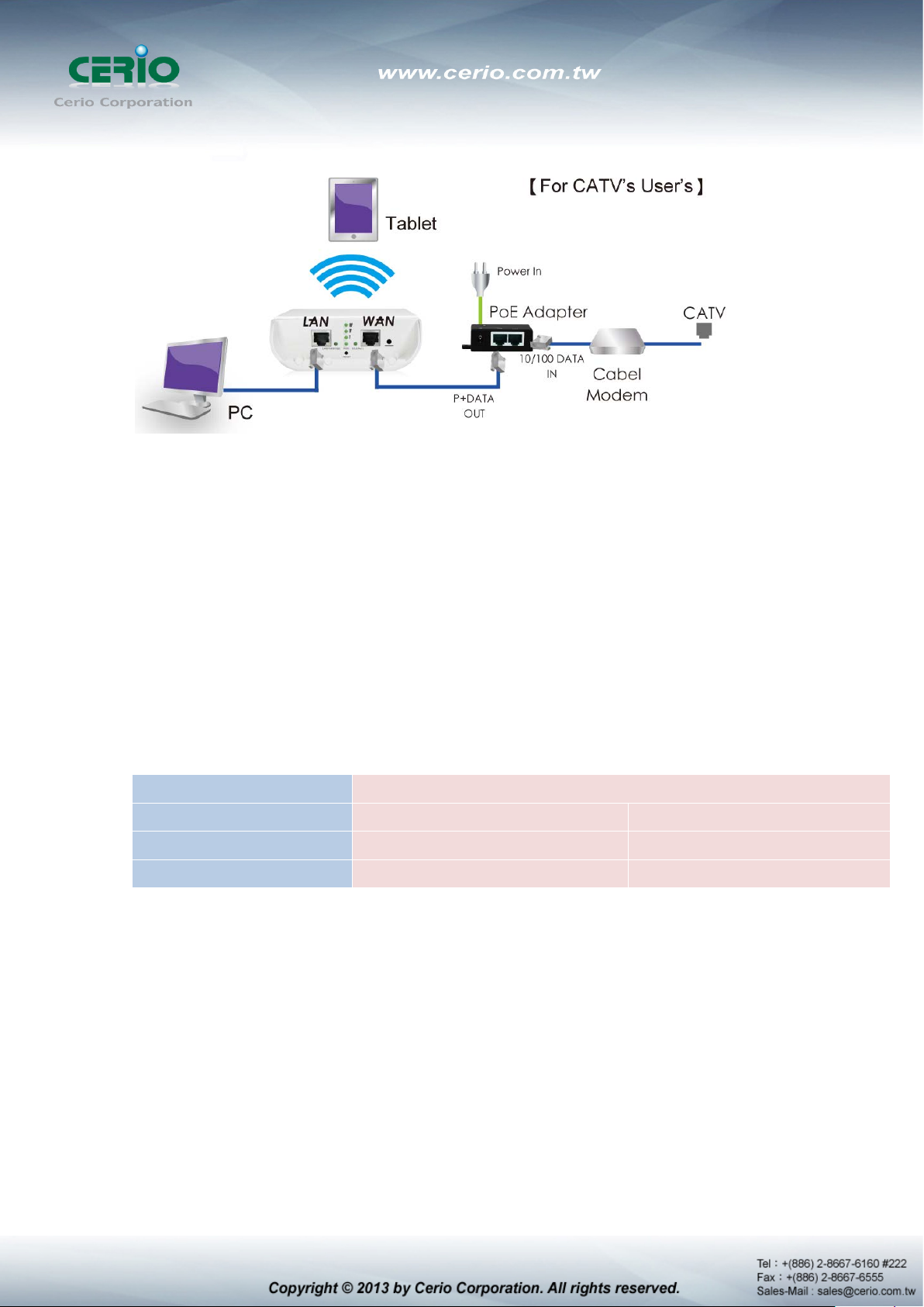
5) For CATV User’s
1.7 Software Configuration
DT-300N supports web-based configuration. Upon the completion of hardware installation,
DT-300N can be configured through a PC/NB by using its web browser such as Internet Explorer
6.0 or later.
Default IP Address: 192.168.2.254
Default Subnet Mask: 255.255.255.0
Default Username and Password
MODE
Management Account
Username
Password
IP Segment Set-up for Administrator's PC/NB
Set the IP segment of the administrator's computer to be in the same range as DT-300N for
Router , AP , WDS , ( WISP / C li ent Brid ge )+ Repeater AP
Root Account Admin Account
root admin
default admin
accessing the system. Do not duplicate the IP Address used here with IP Address of DT-300N or
any other device within the network.
Example of Segment: (Windows XP)
Click Start -> Settings -> Control Panel, and then “Control Panel” window appears.
Click on “Network Connections”, and then “Network Connections” window appears.
Click right on “ Local Area Connection”, and select Properties.
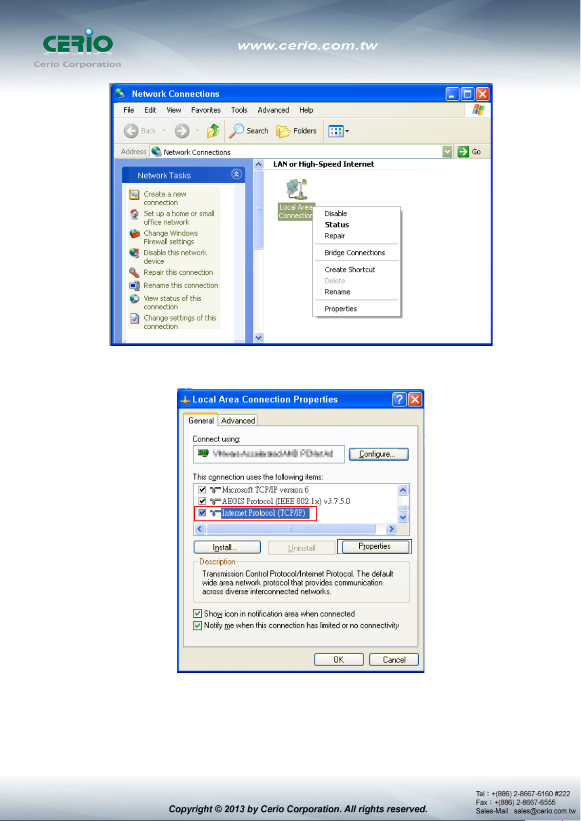
In “Local Area Connection Properties” window, select “Internet Protocol (TCP/IP)”
and click on Properties button.
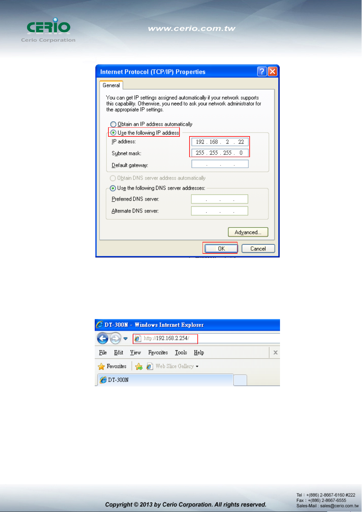
Select “Use the following IP address”, and type in
Launch Web Browser
Launch as web browser to access the web management interface of system by entering the
default IP Address, http://192.168.2.254, in the URL field, and then press Enter.
System Login
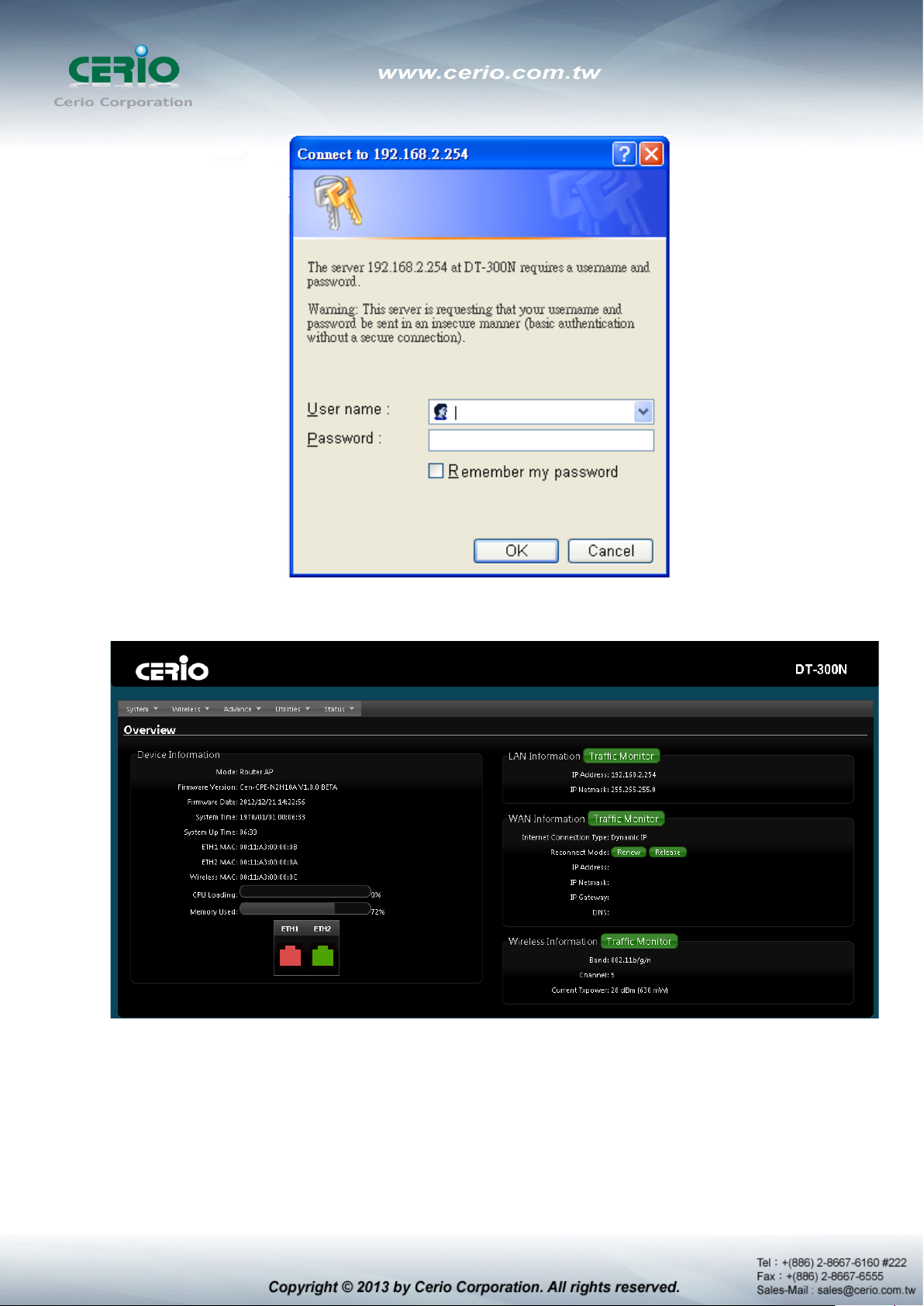
System Overview page will appear after successful login.
1.8 Wizard Setup
The setup wizard is designed to be an 'easy to use' utility that allows quick modification of the
DT-300N UI Web-based GUI interface settings . The wizard should take no longer than 5 minutes
to use. Please be aware that the wiz ard doesn't gi v e full access to all the setup options in DT-300N
in/Outdoor PoE Bridge Router AP.
This is purely because the wizard has been designed for a quick and easy setup ai med at all users.
More advanced users can configure the remaining settings using the advanced settings options
from the setup menu.
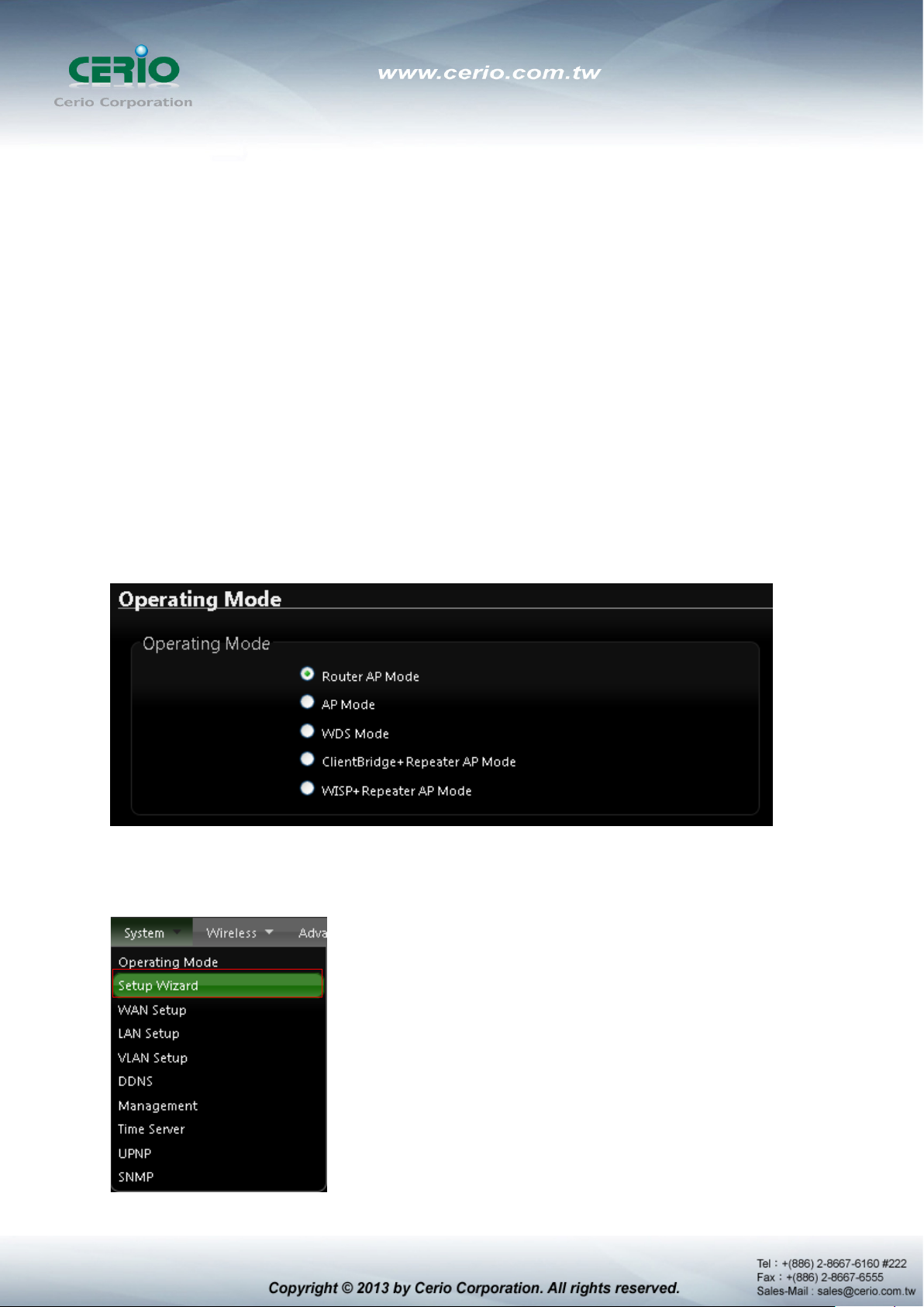
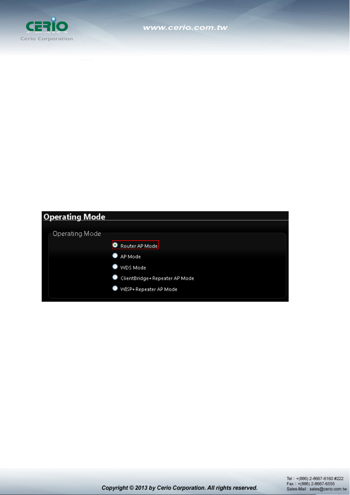
Chose Your Operating Mode
DT-300N supports six operational modes, AP and AP+WDS mode, WDS mode, Client Bridge +
Repeater AP mode, WISP and WISP + Repeater AP mode etc. respectively with built-in remote
management features
Wizard Guide
Please click on System Setup Wizard Next and follow the below guide.
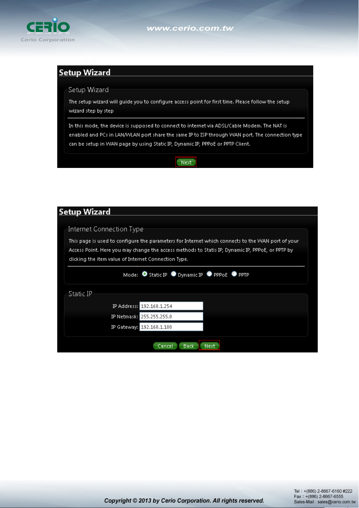
1) Follow And Guide Continuing Setting
Internet Connection type Please base on ISP type to choose WAN connection type.
Cable Modem ISP Type use dynamic IP type. xDSL ISP use PPPoE type and key in your ISP
username and password for xDSL type.
2) DNS If you don’t know for your ISP correct DNS IP address, Please click “No default
DNS server” to follow your ISP DNS related IP address.
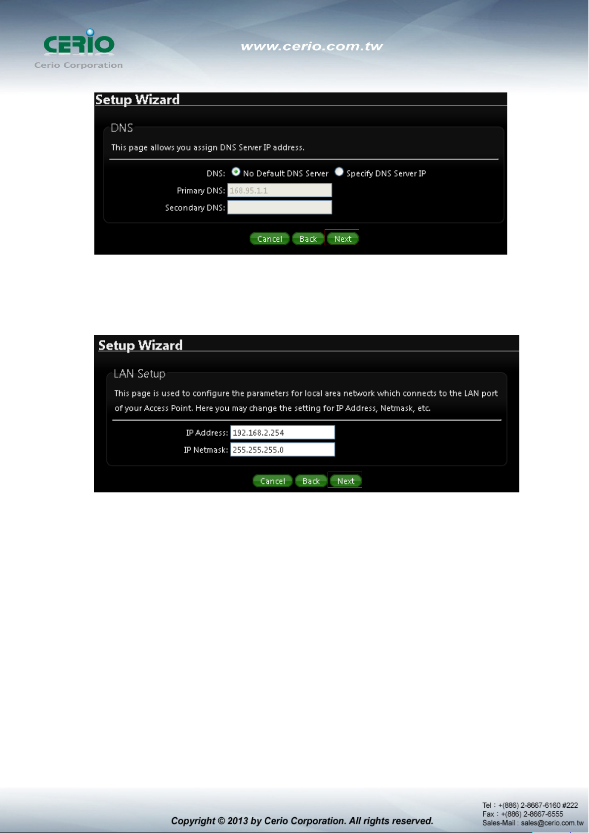
3) LAN setup Here are the instructions for setup y our DT-300N local LAN IP address an d
netmask. If you don’t want change the default DT-300N IP 192.168.2.254 address,
please keep the default and go next setup.
4) DHCP Server Devices connected to system can obtain an IP address automatically
when this DHCP Server service is enabled, Specify the range of IP address to be used by
the DHCP server when assigning IP address to clients, you can keep the default value
and go next setup.
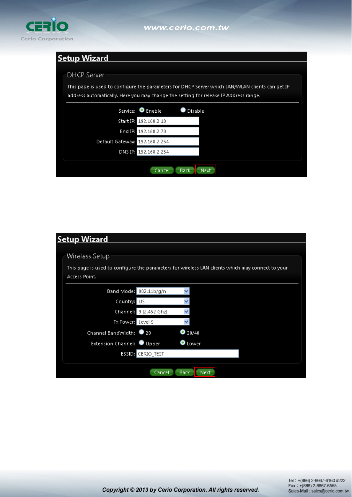
5) Wireless Setup If you are not sure which setting to choose, Please then the default
setting to best WiFi smart channel judgment for auto channel, and adjust the output
power to level9 (100%) Extended service set ID indicated the SSID which the clients used
to connect to the access point ESSID.
6) Wireless Security setup Suggested setting that you use wireless encryption
authentication type for security Type : to “WPA2-PSK” the cipher suite : to “AES”, Key
Type : to “ASCII” for 11n high speed mode.
Pre-shared Key : Enter the information for pre-shared key; Pre-shared key can be either
entered as a 256-bit secret in 64 HEX digits format or 8 to 63 ASCII characters. The
Pre-Shared key sample as “12345678” wireless encryption key for wireless access.

7) Finishing Wizard
Click Finish button to save your setting . please wait till completion of the reboot process.
2. Router AP Mode Configuration
When Router AP mode is chosen, the system can be configured as an Router AP mode. This section
provides detailed explanation for users to configure in the Router AP mode with help of illustrations. In
the Router AP mode, functions listed in the table below are also available from the Web-based GUI
interface.
2.1 Chose Your Operating Mode ( Router AP Mode )
CERIO DT-300N Supports six operational modes, AP and AP+WDS mode, WDS mode, Client
Bridge + Repeater AP mode, WISP and WISP + Repeater AP mode etc. respectively with
built-in remote management features.
The system administrator can set the desired mode via this page, and then configure the system
according to their deployment needs, Please click on System -> Operating Mode and follow the
below setting.
2.2 External Network Connection
Network Requirement
It can be used as an Router AP with WDS function. In this mode, CERIO DT-300N is a gateway
enabled with NAT and DHCP Server functions. The wireless clients connected to Internet.
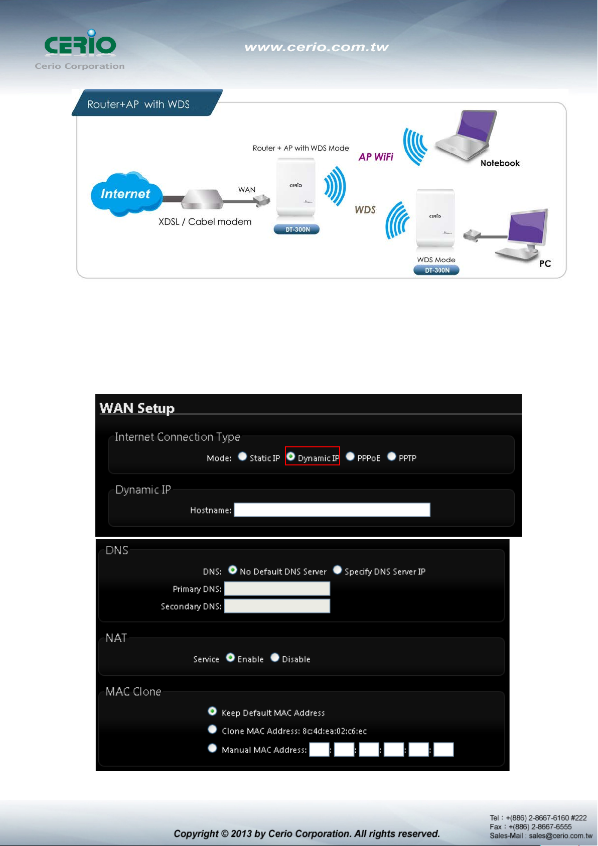
Configure WAN Setup
It can be used as an Router AP with WDS function. In this mode, DT-300N is a gateway
enabled with NAT and DHCP Server functions. The wireless clients connected to Internet.
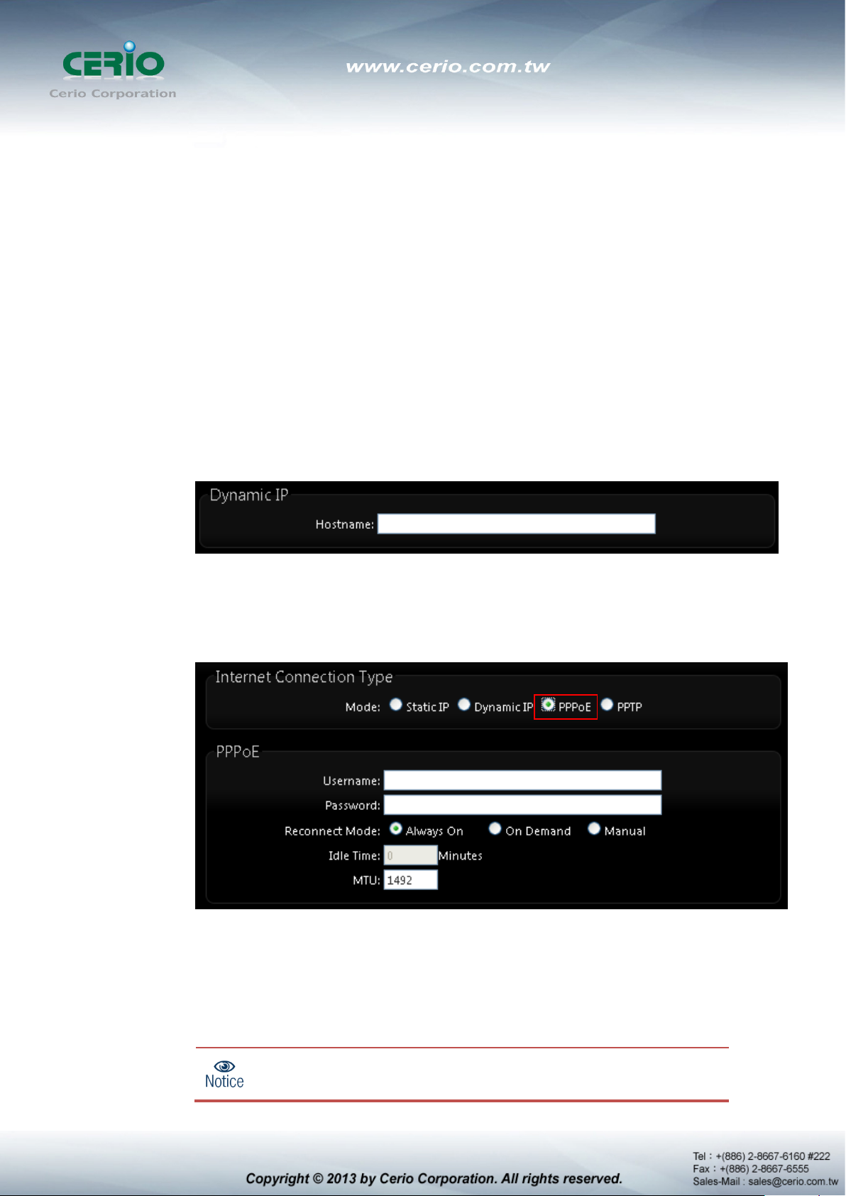
There are three connection types for the WAN port : Static IP, Dynamic IP, PPPoE and
PPTP. Please click on System -> WAN and follow the below setting.
is enabled at the “On Demand” mode, the
Mode : By default, it’s “Static IP”. Check “Static IP”, “Dynamic IP”, “PPPoE” or “PPTP”to
set up system WAN IP
Static IP : Users can manually setup the WAN IP address with a static IP provided
by WISP.
IP Address : The IP address of the WAN port; default IP address is 192.168.1.254
IP Netmask : The Subnet mask of the WAN port; default Netmask is 255.255.255.0
IP Gateway : The default gateway of the WAN port; default Gateway is 192.168.1.1
Dynamic IP : Please consult with WISP for correct wireless settings to associate
with WISP AP before a dynamic IP, along with related IP settings including DNS can
be available from DHCP server. If IP Address is not assigned, please double check
with your wireless settings and ensure successful association. Also, you may go to
“WAN Information” in the Overview page to click Release button to release IP
address and click Renew button to renew IP address again.
Hostname : The Hostname of the WAN port
PPPoE : To create wireless PPPoE WAN connection to a PPPoE server in network.
User Name : Enter User Name for PPPoE connection
Password : Enter Password for PPPoE connection
Reconnect Mode :
Always on – A connection to Internet is always maintained.
On Demand – A connection to Internet is made as needed.
When Time Server
“Reconnect Mode” will turn out “Always on”.
is enabled at the “On Demand” mode, the
Manual – Click the “Connect” button on “WAN Information” in the Overview page
to connect to the Internet.
Idle Time : Time to last before disconnecting PPPoE session when it is idle. Enter
preferred Idle Time in minutes. Default is “0”, indicates disabled. When Idle time is
disabled, the “Reconnect Mode” will turn out “Always on”
MTU : By default, it’s 1492 bytes. MTU stands for Maximum Transmission Unit.
Consult with WISP for a correct MTU setting.
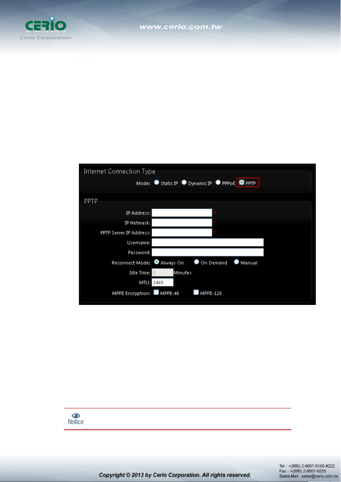
PPTP : The Point-to-Point Tunneling Protocol (PPTP) mode enables the
implementation of secure multi-protocol Virtual Private Networks (VPNs) through
public networks.
IP Address : The IP address of the WAN port
IP Netmask : The Subnet mask of the WAN port
PPTP Server IP Address : The IP address of the PPTP server
User Name : Enter User Name for PPTP connection
Password : Enter Password for PPTP connection
Reconnect Mode :
Always on – A connection to Internet is always maintained.
On Demand – A connection to Internet is made as needed.
When Time Server
“Reconnect Mode” will turn out “Always on”

Manual – Click the “Connect” button on “WAN Information” in the Overview page
to connect to the Internet.
Idle Time : Time to last before disconnecting PPPoE session when it is idle. Enter
preferred Idle Time in minutes. Default is “0”, indicates disabled. When Idle time is
disabled, the “Reconnect Mode” will turn out “Always on”
MTU : By default, it’s 1460 bytes. MTU stands for Maximum Transmission Unit.
Consult with WISP for a correct MTU setting.
MPPE Encryption : Microsoft Point-to-Point Encryption (MPPE) encrypts data in
Point-to-Point Protocol(PPP)-based dial-up connections or Point-to-Point Tunneling
Protocol (PPTP) virtual private network (VPN) connections. 128-bit key (strong)
and 40-bit key (standard) MPPE encryption schemes are supported. MPPE
provides data security for the PPTP connection that is between the VPN client and
the VPN server.
DNS : Check “No Default DNS Server” or “Specify DNS Server IP” radial button as
desired to set up system DNS.
Primary : The IP address of the primary DNS server.
Secondary : The IP address of the secondary DNS server.
NAT : The NAT support Enable and Disable Service
MAC Clone : The MAC address is a 12-digit HE X code uni quely assigned to hardware a s
identification. Some ISPs require you to register a MAC address in order to access to
Internet. If not, you could use default MAC or clone MAC from a PC.
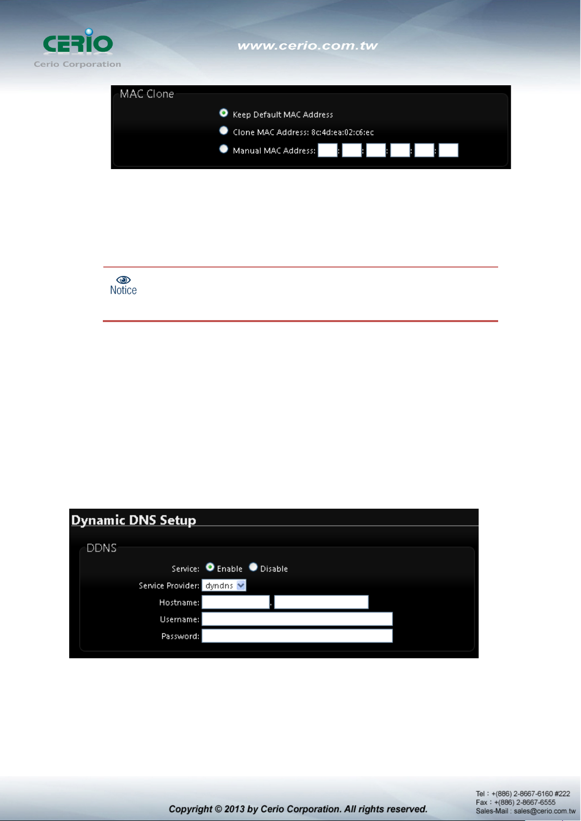
The Clone MAC Address field will display MAC address of the PC
connected to system. Click “Save” button can make clone MAC
Keep Default MAC Address : Keep the default MAC address of WAN port on the
system.
Clone MAC Address : If you want to clone the MAC address of the PC, then click
the Clone MAC Address button. The system will automatically detect your PC's
MAC address.
effective.
Manual MAC Address : Enter the MAC address registered with your ISP.
Click Save button to save your changes. Click Reboot button to activate your changes
2.3 Configure DDNS Setup
Dynamic DNS allows you to map domain name to dynamic IP address. Pl ease cli ck on System ->
DDNS Setup and follow the below setting.
Enabled: By default, it’s “Disable”. The mapping domain name won’t change when
dynamic IP changes. The beauty of it is no need to remember the dynamic WAP IP while
accessing to it.
Service Provider: Select the preferred Service Provider from the drop-down list including
dyndns, dhs, ods and tzo
Hostname: Host Name that you register to Dynamic-DNS service and export.
User Name & Password: User Name and Password are used to login DDNS service.
Click Save button to save your changes. Click Reboot button to activate your changes
2.4 Configure DT-300N LAN IP Address
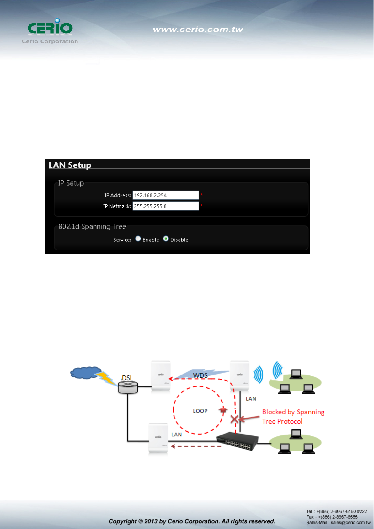
Here are the instructions for how to setup the local IP Address and Netmask. Please click on
System -> LAN and follow the below setting.
LAN IP Setup : The administrator can manually setup the LAN IP address.
IP Address : The IP address of the LAN port; default IP address is 192.168.2.254
IP Netmask : The Subnet mask of the LAN port; default Netmask is 255.255.255.0
802.1d Spanning Tree :
The spanning tree network protocol provides a loop free topology for a bridged LAN
between LAN interface and 8 WDS interfaces from wds0 to wds7. The Spanning Tree
Protocol, which is also referred to as STP, is defined in the IEEE Standard 802.1d.
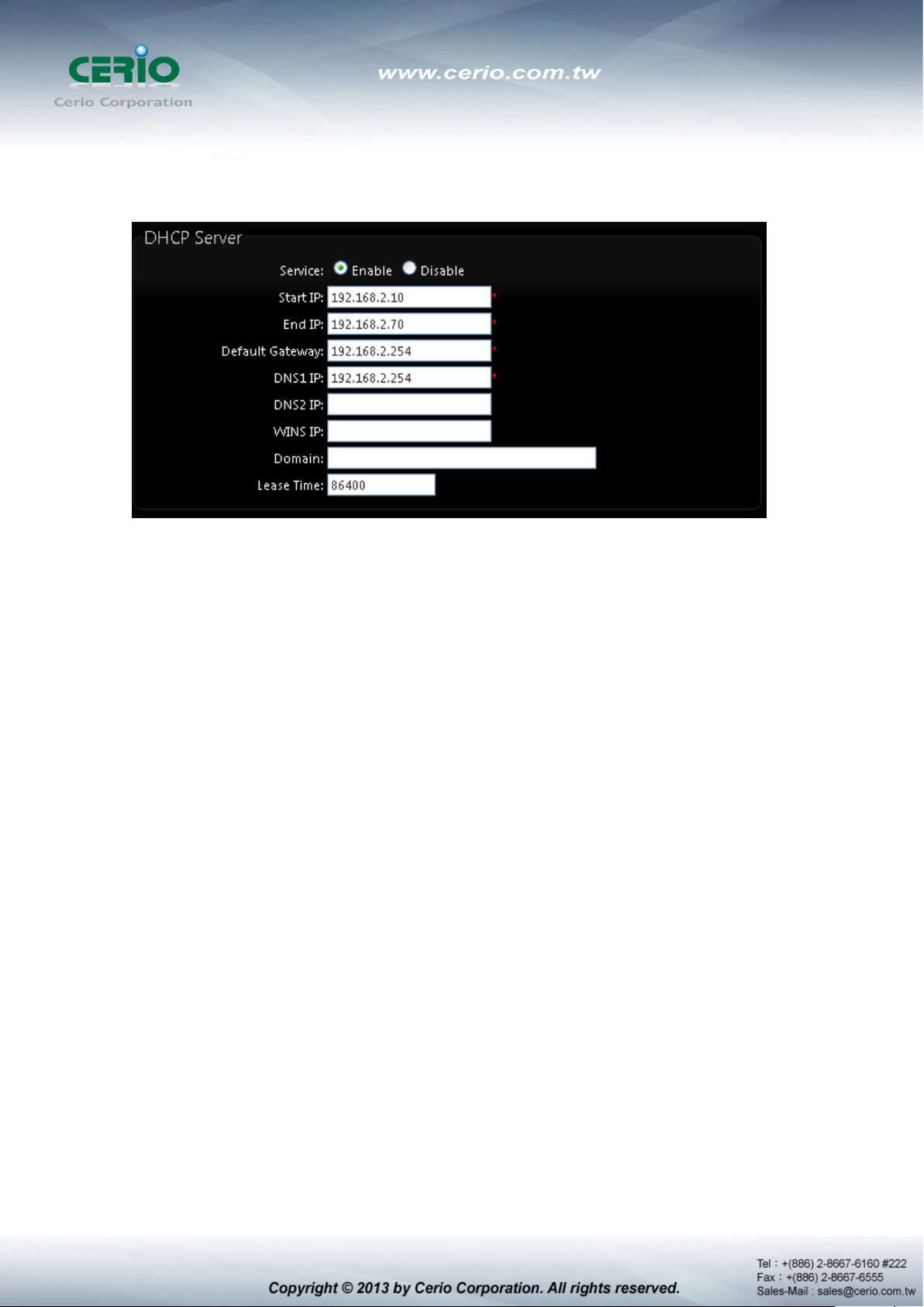
DHCP Setup : Devices connected to the system can obtain an IP address automatically
when this service is enabled.
DHCP : Check Enable button to activate this function or Disable to deactivate this
service.
Star t I P / End IP: Specify the range of IP addresses to be used by the DHCP server
when assigning IP address to clients. The default range IP address is 192.168.2.10
to 192.168.2.70, the netmask is 255.255.255.0
DNS1 I P : Enter IP address of the first DNS server; this field is required.
DNS2 I P : Ent er IP address of the second DNS server; this is optional.
WINS IP : Enter IP address of the Windows Internet Name Service (WINS) server;
this is optional.
Domain : Enter the domain name for this network.
Lease Time : T he IP addresses given out by the DHCP server will only be valid for
the duration specified by the lease time. Increasing the time ensure client operation
without interruptions, but could introduce potential conflicts. Lowering the lease time
will avoid potential address conflicts, but might cause more interruptions to the client
while it will acquire new IP addresses from the DHCP server. Default is 86400
seconds
Click Save button to save your changes. Click Reboot button to activate your
changes

2.5 Wireless General Setup
The administrator can change the data transmission, channel and output power settings for the
system. Please click on Wireless -> General Setup and follow the below setting.
MAC Address : The MAC address of the Wireless interface is displayed here.
Band Mode : Select an appropriate wireless band; bands available are 801.11 b/g/n mixed
mode
Country : a region, the DT-300Nsupport region for US,ETSI and Japan
Channel : Choosing the best WiFi channel
Auto Scan : Smart channel judgment, the function can auto choose use best Channel
AP List : the function support search neighborhood AP and print site survey list
TX Power : You can ad just the output pow er of the system to get the appropriate cov erage for
your wireless network. Specify digit numbers between level 1 to level 9 (the unit is %) for your
environment. If you are not sure which setting to choose, then keep the default setting level 9
(100%).
HT Physical Mode

HT TxStream/RxStream : By default, it's 2
Channel Bandwidth : The "20/40” MHz option is usually best. The other option is
available for special circumstances.
Extension Channel : Only for Channel Bandwidth “40” MHz. Select the desired channel
bonding for control.
MCS : This parameter represents transmission rate. By default (Auto) the fastest possible
transmission rate will be selected. You have the option of selecting the speed if
necessary.
Shout GI : Short Guard Interval, by default, it's “Enable”. it's can increase throughput.
However, it can also increase error rate in some installations, due to increased sensitivity
to radio-frequency reflections. Select the option that works best for your installation.
Aggregation : By default, it's “Enable”. To “Disable” to deactivated Aggregation.
A part of the 802.11n standard (or draft-standard). It allows sending multiple frames per
single access to the medium by combining frames together into one larger frame. It
creates the larger frame by combining smaller frames with the same physical source and
destination end points and traffic class (i.e. QoS) into one large frame with a common
MAC header.
Aggregation Frames : The Aggregation Frames is in the range of 2~64, default is 32. It
determines the number of frames combined on the new larger frame.
Aggregation Size : The Aggregation Size is in the range of 1024~65535, default is
50000. It determines the size (in Bytes) of the larger frame.
Change these settings as described here and click Save button to save your changes. Click
Reboot button to activate your chan ges. The i tems in this pa ge is for AP' s RF general settings
and will be applied to all VAPs and WDS Link.

2.6 Configure Wireless Advanced Setup
The administrator can change the Slot Time, ACK Timeout, RTS threshold and fragmentation
threshold settings for the system. Please click on Wireless -> Advanced Setup and follow the
below setting.
Slot Time : Slot time is in the range of 9~1489 and set in unit of microsecond. The default
value is 9 microsecond.
Slot time is the amount of time a device waits after a collision before retransmitting a
packet. Reducing the slot time decreases the overall back-off, which increases
throughput. Back-off, which is a multiple of the slot time, is the random length of time a
station waits before sending a packet on the LAN. For a sender and receiver own right of
the channel the shorter slot time help manage shorter wait time to re-tra n smit from
collision because of hidden wireless clients or other causes. When collision sources can
be removed sooner and other senders attempting to send are listening the
channel(CSMA/CA) the owner of the channel should continue ownership and finish their
transmission and release the channel. Then, following ownership of the channel will be
sooner for the new pair due to shorter slot time. However, when long duration of existing
collision sources and shorter slot time exist the owners might experience subsequent
collisions. When adjustment to longer slot time can’ t improve per formance then RTS/CTS
could supplement and help improve performance.

ACK Timeout : ACK timeo ut is in t he range of 1~372 and set in unit of microsecond. The
default value is 64 microsecond.
All data transmission in 802.11b/g request an “Acknowledgement” (ACK) send by receiving
radio. The transmitter will resend the original packet if correspondent ACK failed to arrive
within specific time interval, also refer to as “ACK Timeout”.
ACK Timeout is adjustable due to the fact that distance between two radio links may vary in
different deployment. ACK Timeout makes significant influence in performance of long
distance radio link. If ACK Timeout is set too short, transmitter will start to “Resend” packet
before ACK is received, and throughput become low due to excessively high
re-transmission.
ACK Timeout is best determined by distance between the radios, data rate of average
environment. The Timeout value is calculated based on round-trip time of packet with a little
tolerance, So, if experiencing re-transmissions or poor performance the ACK Timeout could
be made longer to accommodate.
Slot Time and ACK Timeout settings are for long distance lin ks. It is impo rtant to
tweak settings to achieve the optimal result based on requirement.
Beacon Interval : Beacon Interval is in the range of 40~3500 and set in unit of millisecond.
The default value is 100 msec.
Access Point (AP) in IEEE 802.11 will send out a special approximated 50-byte frame, called
“Beacon”. Beacon is broadcast to all the stations, provides the basic information of AP such
as SSID, channel, encryption keys, signal strength, time stamp, support data rate.
All the radio stations received beacon recognizes the existence of such AP, and may
proceed next actions if the information from AP matches the requirement. Beacon is sent
on a periodic basis, the time interval can be adjusted.
By increasing the beacon interval, you can reduce the number o f beacons a nd associated
overhead, but that will likely delay the association and roaming process because stations
scanning for available access points may miss the beacons. You can decrease the
beacon interval, which increases the rate of beacons. This will make the association and
roaming process very responsive; however, the network will incur additional overhead
and throughput will go down.

DTIM Interval : The DTIM interval is in the range of 1~255. The default is 1.
DTIM is defined as Delivery Traffic Indication Message. It is used to notify the wireless
stations, which support power saving mode, when to wake up to receive multicast frame.
DTIM is necessary and critical in wireless environment as a mechanism to fulfill
power-saving synchronization.
a DTIM interval is a count of the number of beacon frames that must occur before the
access point sends the buffered multicast frames. For instance, if DTIM Interval is set to 3,
then the Wi-Fi clients will expect to receive a multicast frame after receiving three Beacon
frame. The higher DTIM interval will help power saving and possibly decrease wireless
throughput in multicast applications.
RTS Threshold : TRTS Threshold is in the range of 1~2347 byte. The default is 2347 byte.
The main purpose of enabling RTS by chan ging RTS th reshold is to reduce possible colli sions
due to hidden wireless clients. RTS in AP will be enabled automatically if the packet size is
larger than the Threshold value. By default, RTS is disabled in a normal environment supports
non-jumbo frames.
Short Preamble : By default, it’s “Enable”. To Disable is to use Long 128-bit Preamble
Synchronization field.
The preamble is used to signal "here is a train of data coming" to the receiver. The short
preamble provides 72-bit Synchronization field to improve WLAN transmission efficiency with
less overhead.
IGMP Snooping : the process of listening to Internet Group Management Protocol (IGMP)
network traffic. The feature allows a network switch to listen in on the IGMP conversation
between hosts and routers. By listening to these c onversations the switch maintains a map of
which links need which IP multicast streams. Multicasts may be filtered from the links which
do not need them and thus controls which ports receive specific multicast traffic.
Greenfield : In wireless WLAN technology, greenfield mode is a feature of major components
of the 802.11n specification. The greenfield mode feature is designed to improve efficiency
by eliminating support for 802.11b/g devices in an all draft-n network. In greenfield mode the
network can be set to ignore all earlier standards.

Queue
Data
AP to Clients
Priority
Description
WMM QoS : This affects traffic flowing from the access point to the client station.
Configuring QoS options consists of setting parameters on existing queues for different types
of wireless traffic. You can configure different minimum and maximum wait times for the
transmission of packets in each queue based on the requirements of the media being sent.
Queues automatically provide minimum transmission delay for Voice, Video, multimedia, and
mission critical applications, and rely on best-effort parameters for traditional IP data.
As an Example, time-sensitive Voice & Video, and multimedia are given effectively higher
priority for transmission (lower wait times for channel access), while other applications and
traditional IP data which are less time-sensitive but often mor e data-intensive are expected to
tolerate longer wait times.
AC Type:
Transmitted
AC_BK Background Low High throughput. Bulk data that requires maximum
throughput and is not time-sensitive is sent to this
queue (FTP data, for example).
AC_BE Best Effort Medium Medium throughput and delay. Most traditional IP
data is sent to this queue.
AC_VI Video High Minimum delay. Time-sensitive video data is
automatically sent to this queue.
AC_VO Voice High Time-sensitive data like VoIP and streaming media
are automatically sent to this queue.

CWmin:Minimum Contention Window. This parameter is input to the algorithm that
determines the initial random backoff wait time ("window") for retry of a transmission.
The value specified here in the Minimum Contention Window is the upper limit (in
milliseconds) of a range from which the initial random backoff wait time is determined.。
CWmax:Maximum Contention Window. The value specified here in the Maximum
Contention Window is the upper limit (in milliseconds) for the doubling of the random
backoff value. This doubling continues until either the data frame is sent or the
Maximum Contention Window size is reached. Once the Maximum Contention Window
size is reached, retries will continue until a maximum number of retries allowed is
reached. Valid values for the "cwmax" are 1, 3, 7, 15, 31, 63, 127, 255, 511, or 1024.
The value for "cwmax" must be higher than the value for "cwmin".。
AIFS:The Arbitration Inter-Frame Spacing Number specifies a wait time (in milliseconds)
for data frames。
TxOP Limit:Transmission Opportunity is an interval of time when a WME AP has the
right to initiate transmissions onto the wireless medium (WM). This value specifies (in
milliseconds) the Transmission Opportunity (TXOP) for AP; that is, the interval of time
when the WMM AP has the right to initiate transmissions on the wireless network.。
ACM bit:Admission Control Mandatory, ACM only takes effect on AC_VI and AC_VO.
When you do not click Checkbox, it means that the ACM is controlled by the connecting
AP. If you click Checkbox, it means that the Client is in charge。
No ACK policy bit:Acknowledgment Policy, WMM defines two ACK policies: Normal
ACK and No AC K. Clic k “ Checkbox” indicates “No ACK”
When the no acknowledgement (No ACK) policy is used, the recipient does not
acknowledge received packets during wireless packet exchange. This policy is suitable
in the environment where communication quality is fine and interference is weak. While
the No ACK policy helps improve transmission efficiency, it can cause increased packet
loss when communication quality deteriorates. This is because when this policy is used,
a sender does not retransmit packets that have not been received by the recipient.
When the Normal ACK policy is used, the recipient acknowledges each received uncast
packet.。

2.7 Create Virtual AP – Virtual AP Setup
The administrator can create Virtual AP via this page. Please click on Wireless -> Virtual AP
Setup and follow the below setting.
VAP: Display number of system's Virtual AP.
MAC Address : The MAC address of the VAP Interface is displayed here. When you
enable AP and reboot system, the MAC address will display here
ESSID: Display Virtual AP's ESSID; default is AP00~AP07.
Status: Display VAP status; default VAP0 is always on and only VAP0 can support WPS
function.
Security Type: Display Virtual AP's Security Type; default is disabled.
MAC Filter Setup: Click “Setup” button for configuring Virtual AP's Access Control List.
VAP Edit: Click “Edit” button for configuring Virtual AP's settings and security type.
Change these settings as described here and click Save button to save your changes. Click
Reboot button to activate your changes
2.8 Virtual AP General Configuration
For each Virtual AP, administrators can configure general settings and security type. Click
Wireless -> Virtual AP Setup, click “Edit” of Virtual AP List and then Virtual AP Configuration
page appears.

ESSID: Extended Service Set ID indicates the SSID which the clients used to connect to
the VAP. ESSID will determine the service type of a client which is assigned to the
specified VAP.

Hidden SSID: Select this option to enable the SSID to broadcast in your network. When
configuring the network, it is suggested to enable this function but disable it when the
configuration is complete. With this enabled, someone could easily obtain the SSID
information with the site survey software and get unauthorized access to a private network.
With this disabled, network security is enhanced and can prevent the SSID from begin
seen on networked.
Client I solation: Select Enable, all clients will be isolated from each other, that means all
clients can not reach to other clients.
IAPP: Inter Access-Point Protocol is designed for the enforcement of unique association
throughout a ESS(Extended Service Set) and for secure exchange of station's security
context between current access point (AP) and new AP during hand off period.
Notice: IAPP only used on WPA-PSK and WPA2-PSK security type. Only one of
VAPs can be enabled.
Maximum Clients: Enter maximum number of clients to a desired number. For example,
while the number of client is set to 32, only 32 clients are allowed to connect with this VAP.
VL AN Tag(ID): Virtual LAN, the system supports tagged VLAN. To enable VLAN function;
valid values are from 0 to 4094.
Securit y Type: Select the desired security type from the drop-down list; the options are
WEP, WPA-PSK, WPA2-PSK, WPA-Enterprise, WPA2-Enterprise and WEP 802.1X.
Disable: Data are unencrypted during transmission when this option is selected.
WEP: WEP, Wired Equivalent Privacy, is a data encryption mechanism based on a
64-bit, 128-bit or 152-bit shared key. Select WEP as the security type from the drop
down list as desired.

Key Length: The key size of WEP encryption can be 64bit, 128bit or 152bit.
WEP auth method: You can select the appropriate value: Open system (If
enabling this mode, there is no need authentication to access AP or Wireless NIC)
or Shared (Only those who are sharing the same key with the AP can connect
with it).
Key Index: You can select the Key which you want to use. Other wireless station
must have the same key value to connect with DT-300N, 4 different WEP keys
can be configured at the same time, but only one is used. Effective key is set with
a choice of WEP Key 1, 2, 3 or 4.
WEP Key #: You can chose either HEX or ASCII for y our WEP key value, for 64bit
encryption strength can use 10 digits for HEX (0~9, a~f and A-F) or 5 digits for
ASCII (0~9, a~z and A~Z), for 128bit encryption strength can use 26 digits for
HEX (0~9, a~f and A-F) or 13 digits for ASCII (0~9, a~z and A~Z), for 152bit
encryption strength can use 32 digits for HEX (0~9, a~f and A-F) or 16 digits for
ASCII (0~9, a~z and A~Z)
WPA-PSK (or WPA2-PSK): WPA-PSK is short for W-Fi Protected
Access-Pre-Shared Key. WPA-SPK uses the same encryption way with WPA, and the
only difference between them is that WPA-PSK recreates a simple shared key, instead
of using the user’s certification.
Cipher Suite: You can chose use AES or TK IP w i th your WPA / WPA2 encryption
method,

AES is s hor t for “Advanced Encryption Standard”, The AES cipher is specified
as a number of repetitions of transformation rounds that convert the input plaintext
into the final output of ciphertext. Each round consists of several processing steps,
including one that depends on the encryption key. A set of reverse rounds are
applied to transform ciphertext back into the original plaintext using the same
encryption key.
TKIP is short for “Temporal Key Integrity Protocol”, TKIP scrambles the keys
using a hashing algorithm and, by adding an integrity-checking feature, ensures
that the keys haven’t been tampered with.
Group Key Update Period: This time interval for re-keying GTK
(broadcast/multicast encryption keys) in seconds. Enter the time-length required;
the default time is 600 seconds.
Master Key Update Period: This time interval for re-keying GMK (master key
used internally to generate GTKs) in seconds. Enter the time-length required; the
default time is 83400 seconds.
Key Type: Check on the respected button to enable either ASCII or HEX format
for the Pre-shared Key.
Pre-Shared Key: Enter the information for pre-shared key; the format of the
information shall according to the key type selected. Pre-shared key can be either
entered as a 256-bit secret in 64 HEX digits format, or 8 to 63 ASCII characters.
WPA-Enterprise (or WPA2-Enterprise) General Setting
The RADIUS authentication and encryption will be both enabled if this selected.

General Setting :
Cipher Suite: You can chose use AES or TK IP w i th your WPA / WPA2 encryption
method, AES is short for “Advanced Encryption Standard”, The AES cipher is
specified as a number of repetitions of transformation rounds that convert the
input plaintext into the final output of ciphertext. Each round consists of several
processing steps, including one that depends on the encryption key. A set of
reverse rounds are applied to transform ciphertext back into the original plaintext
using the same encryption key.
TKIP is short for “Temporal Key Integrity Protocol”, TKIP scrambles the keys
using a hashing algorithm and, by adding an integrity-checking feature, ensures
that the keys haven’t been tampered with.
Group Key Update Period: This time interval for re-keying GTK
(broadcast/multicast encryption keys) in seconds. Enter the time-length required;
the default time is 600 seconds.
Master Key Update Period: This time interval for re-keying GMK (master key
used internally to generate GTKs) in seconds. Enter the time-length required; the
default time is 83400 seconds.
EAP Reauth Period: This time interval for re- authentication in seconds. Enter the
time-length required; the default time is 3600 seconds; 0 = disable
re-authentication.

Authentication RADIUS Server Settings
Authentication Server: Enter the IP address of the Authentication RADIUS
server.
Port: The port number used by Authentication RADIUS server. Use the default
1812 or enter port number specified.
Shared secret: The secret key for system to communicate with Authentication
RADIUS server. Support 1 to 64 characters.
Accounting Server: Check on the respected button to enable either Enable or
Disable accounting RADIUS server.
Secondary Authentication RADIUS Server
Authentication Server: Enter the IP address of the Authentication RADIUS
server.
Port: The port number used by Authentication RADIUS server. Use the default
1812 or enter port number specified.
Shared secret: The secret key for system to communicate with Authentication
RADIUS server. Support 1 to 64 characters.
WEP 802.1x : When WEP 802.1x Authentication is enabled, please refer to the
following Dynamic WEP and RADIUS settings to complete the configuration.

Dynamic WEP Settings
WEP Key length: Check on the respected button to enable either 64bits or
128bits key length. The system will automatically generate WEP keys for
encryption.
WEP Key Update Period: The time interval WEP will then be updated; the unit is
in seconds; default is 300 seconds; 0 = do not rekey.
EAP Reauth Period: EAP re-authentication period in seconds; default is 3600; 0
= disable re-authentication.
Authentication RADIUS Server Settings
Authentication Server: Enter the IP address of the Authentication RADIUS
server.
Port: The port number used by Authentication RADIUS server. Use the default
1812 or enter port number specified.
Shared secret: The secret key for system to communicate with Authentication
RADIUS server. Support 1 to 64 characters.
Accounting Server: Check on the respected button to enable either Enable or
Disable accounting RADIUS server.
Secondary Authentication RADIUS Server
Authentication Server: Enter the IP address of the Authentication RADIUS
server.

Port: The port number used by Authentication RADIUS server. Use the default
1812 or enter port number specified.
Shared secret: The secret key for system to communicate with Authentication
RADIUS server. Support 1 to 64 characters.
VAP MAC Filter Setup
In this function, the administrator can be allow or reject clients to access Virtual AP. Please click
on Wireless -> Virtual AP Setup -> MAC Filter Setup, click “Setup” of Virtual AP List and then
MAC Filter Setup page appears. Follow the below setting.
Action: Select the desired access control type from the drop-down list; the options are
Disable, Allow or Reject .
Only Allo w Lis t MAC: Def ine cert ain wireless clients in the list which will have granted
access to the Access Point w hil e the access will be denied for all the remaining cl ients –
Action Type is set to “Only Allow List MAC”.
Only Deny List MAC: Define certain wireless clients in the list which will have denied
access to the Access Point while the acce ss w ill be granted for all the re maining clients Action Type is set to “Only Deny List MAC”.
MAC Access Control is the weakest security approach. WPA or WPA2 security
methods should be used when possible.

2.9 WDS Setup - Expand your Wireless Network
Service: By default, it's “Disable”. To “Enable” to activate WDS
Enable: Click Enable checkbox to create WDS link.
WDS Peer's MAC Address: Enter the MAC address of WDS peer.
Description: Description of WDS link.
Change these settings as described here and click Save button to save your changes. Click
Reboot button to activate your changes.
2.10 WDS Status
The Peers MAC Address, antenna 0/1 received signal strength, phy mode and channel bandwidth
for each WDS are available.
MAC Address : Display MAC address of WDS peer.
RSSI : Indicate the RSSI of the respective WDS's link.
TX/RX Rate : Indicate the TX/RX Rate of the respective WDS's link
TX/RX SEQ : Indicate the TX/RX sequence of the respective WDS's link
Disconnect : Administrator can kick out a specific client, click “Delete” button t o kick out
specific WDS's link.

2.11 Associated Clients
The administrator can obtain detailed wireless information and all associated clients status via this
page. Please click on Wireless -> Associated Clients. The the Associated Clients Status appears.
Wireless Information : Display the Virtual AP configuration information of the system.
VAP : Display number of system's Virtual AP.
ESSID : Extended Service Set ID of the Virtual AP.
Status : Display Virtual AP status currently.
Security Type : Security type activated by the Virtual AP.
Clients : Number of clients currently associated to the Virtual AP.

3. AP Mode Configuration
When AP mode is chosen, the system can be configured as an Access Point. This section provides
detailed explanation for users to configure in the AP mode with help of illustrations. In the AP mode,
functions listed in the table below are also available from the Web-based GUI interface.
3.1 Chose Your Operating Mode ( AP Mode )
DT-300N Operating mode support four operational modes, AP mode, the WDS mode, the CPE
mode and the Client Bridge + Repeater AP mode, respectively with built-in remote management
features.
The system administrator can set the desired mode via this page, and then configure the system
according to their deployment needs, Please click on System -> Operating Mode and follow the
below setting.
3.2 External Network Connection
Network Requirement
Normally, DT-300N connects to a wired LAN and provides a wireless connection point to
associate with wireless client. Then, Wireless clients could access to LAN or Internet by
associating themselves with DT-300N set in AP mode.

3.3 Configure DT-300N LAN IP Address
Here are the instructions to setup the local IP Address and Netmask
Please click on System -> LAN and follow the below setting.
Ethernet Connection Type
Check either “Static IP” or “Dynamic IP” button as desired to set up the system IP of LAN port.
Static IP: The administrator can manually setup the LAN IP address when static IP is
available/ preferred.
IP Address : The IP address of the LAN port; default IP address is 192.168.2.254
IP Netmask : The Subnet mask of the LAN port; default Netmask is 255.255.255.0
IP Gateway : The default gateway of the LAN port
Dynamic IP: This configuration type is applicable when the PS-200N-A is connected to a
network with the presence of a DHCP server; all related IP information will be provided by
the DHCP server automatically.

Hostname : The Hostname of the LAN port.
DNS: Check either “No Default DNS Server” or “Specify DNS Server IP” button as desired
to set up the system DNS.
Primary : T he IP address of the primary DNS server.
Secondary : The IP address of the secondary DNS server.
802.1d Spanning Tree
The spanning tree network protocol provides a loop free topology for a bridged LAN between
LAN interface and 8 WDS interfaces from wds0 to wds7. The Spanning Tree Protocol, which
is also referred to as STP, is defined in the IEEE Standard 802.1d
Click Save button to save your changes. Then click Reboot button to activate your changes.
3.4 Wireless General Setup
The administrator can change the data transmission, channel and output power settings for the
system. Please click on Wireless -> General Setup and follow the below setting.

MAC Address : The MAC address of the Wireless interface is displayed here.
Band Mode : Select an appropriate wireless band; bands available are 801.11 b/g/n mixed
mode
Country : a region, the DT-300Nsupport region for US,ETSI and Japan
Channel : Choosing the best WiFi channel
Auto Scan : Smart channel judgment, the function can auto choose use best Channel
AP List : the function support search neighborhood AP and print site survey list
TX Power : You can adjust the output power of the system to get the appropriate cov erage for
your wireless network. Specify digit numbers between level 1 to level 9 (the unit is %) for your
environment. If you are not sure which setting to choose, then keep the default setting level 9
(100%).
HT Physical Mode
HT TxStream/RxStream : By default, it's 2
Channel Bandwidth : The "20/40” MHz option is usually best. The other option is

available for special circumstances.
Extension Channel : Only for Channel Bandwidth “40” MHz. Select the desired channel
bonding for control.
MCS : This parameter represents transmission rate. By default (Auto) the fastest possible
transmission rate will be selected. You have the option of selecting the speed if
necessary.
Shout GI : Short Guard Interval, by default, it's “Enable”. it's can increase throughput.
However, it can also increase error rate in some installations, due to increased sensitivity
to radio-frequency reflections. Select the option that works best for your installation.
Aggregation : By default, it's “Enable”. To “Disable” to deactivated Aggregation.
A part of the 802.11n standard (or draft-standard). It allows sending multiple frames per
single access to the medium by combining frames together into one larger frame. It
creates the larger frame by combining smaller frames with the same physical source and
destination end points and traffic class (i.e. QoS) into one large frame with a common
MAC header.
Aggregation Frames : The Aggregation Frames is in the range of 2~64, default is 32. It
determines the number of frames combined on the new larger frame.
Aggregation Size : The Aggregation Size is in the range of 1024~65535, default is
50000. It determines the size (in Bytes) of the larger frame.
Change these settings as described here and click Save button to save your changes. Click
Reboot button to activate your chan ges. The i tems in this pa ge is for AP' s RF general settings
and will be applied to all VAPs and WDS Link.
3.5 Configure Wireless Advanced Setup
The administrator can change the Slot Time, ACK Timeout, RTS threshold and fragmentation
threshold settings for the system. Please click on Wireless -> Advanced Setup and follow the
below setting.

Slo t Time : Sl ot time is in the range of 9~1489 and set in unit of microsecond. The
default value is 9 microsecond.
Slot time is the amount of time a device waits after a collision before retransmitting a
packet. Reducing the slot time decreases the overall back-off, which increases
throughput. Back-off, which is a multiple of the slot time, is the random length of time a
station waits before sending a packet on the LAN. For a sender and receiver own right of
the channel the shorter slot time help manage shorter wait time to re-tra n smit from
collision because of hidden wireless clients or other causes. When collision sources can
be removed sooner and other senders attempting to send are listening the
channel(CSMA/CA) the owner of the channel should continue ownership and finish their
transmission and release the channel. Then, following ownership of the channel will be
sooner for the new pair due to shorter slot time. However, when long duration of existing
collision sources and shorter slot time exist the owners might experience subsequent
collisions. When adjustment to longer slot time can’ t improve per formance then RTS/CTS
could supplement and help improve performance.
ACK Timeout : ACK tim eout is in the range of 1~372 and set in unit of microsecond.
The default value is 64 microsecond.
All data transmission in 802.11b/g request an “Acknowledgement” (ACK) send by
receiving radio. The transmitter will resend the original packet if correspondent ACK failed
to arrive within specific time interval, also refer to as “ACK Timeout”.

ACK Timeout is adjustable due to the fact that distance between two radio links may vary
in different deployment. ACK Timeout makes significant influence in performance of long
distance radio link. If ACK Timeout is set too short, transmitter will start to “Resend”
packet before ACK is received, and throughput become low due to excessively high
re-transmission.
ACK Timeout is best determined by distance between the radios, data rate of average
environment. The Timeout value is calculated based on round-trip time of packet with a
little tolerance, So, if experiencing re-transmissions or poor performance the ACK
Timeout could be made longer to accommodate.
Slot Time and ACK Timeout settings are for long distance links . It is
important to tweak settings to achieve the optimal result based on
requirement.
Beacon Interval : Beacon Interval is in the range of 40~3500 and set in unit of
millisecond. The default value is 100 msec.
Access Point (AP) in IEEE 802.11 will send out a special approximated 50-byte frame,
called “Beacon”. Beacon is broadcast to all the stations, provides the basic information of
AP such as SSID, channel, encryption keys, signal strength, time stamp, support data
rate.
All the radio stations received beacon recognizes the existence of such AP, and may
proceed next actions if the information from AP matches the requirement. Beacon is sent
on a periodic basis, the time interval can be adjusted.
By increasing the beacon interval, you can reduce the number o f beacons a nd associated
overhead, but that will likely delay the association and roaming process because stations
scanning for available access points may miss the beacons. You can decrease the
beacon interval, which increases the rate of beacons. This will make the association and
roaming process very responsive; however, the network will incur additional overhead
and throughput will go down.
DTIM Interval : The DTIM interval is in the range of 1~255. The default is 1.
DTIM is defined as Delivery Traffic Indication Message. It is used to notify the wireless
stations, which support power saving mode, when to wake up to receive multicast frame.
DTIM is necessary and critical in wireless environment as a mechanism to fulfill
power-saving synchronization.

A DTIM interval is a count of the number of beacon frames that must occur before the
access point sends the buffered multicast frames. For instance, if DTIM Interval is set to
3, then the Wi-Fi clients will expect to receive a multicast frame after receiving three
Beacon frame. The higher DTIM interval will help power saving and possibly decrease
wireless throughput in multicast applications.
RTS Threshold : TRTS Threshold is in the range of 1~2347 byte. The default is 2347
byte.
The main purpose of enabling RTS by changing RTS threshold is to reduce possible
collisions due to hidden wireless clients. RTS in AP will be enabled automatically if the
packet size is larger than the Threshold value. By default, RTS is disabled in a normal
environment supports non-jumbo frames.
Short Preamble : By default, it’s “Enable”. To Disable is to use Long 128-bit Preamble
Synchronization field.
The preamble is used to signal "here is a train of data coming" to the receiver. The short
preamble provides 72-bit Synchronization field to improve WLAN transmission efficiency
with less overhead.
IGMP Snooping : the process of listening to Internet Group Management Protocol (IGMP)
network traffic. The feature allows a network switch to listen in on the IGMP conversation
between hosts and routers. By listening to these conversations the switch maintains a
map of which links need which IP multicast streams. Multicasts may be filtered from the
links which do not need them and thus controls which ports receive specific multicast
traffic.
Greenfield : In wireless WLAN technology, greenfield mode is a feature of major
components of the 802.11n specification. The greenfield mode feature is designed to
improve efficiency by eliminating support for 802.11b/g devices in an all draft-n network.
In greenfield mode the network can be set to ignore all earlier standards.
WMM QoS : This affects traffic flowing from the access point to the client station.
Configuring QoS options consists of setting parameters on existing queues for different
types of wireless traffic. You can configure different minimum and maximum wait times
for the transmission of packets in each queue based on the requirements of the media
being sent. Queues automatically provide minimum transmission delay for Voice, Video,
multimedia, and mission critical applications, and rely on best-effort parameters for
traditional IP data.

Data
AP to Clients
As an Example, time-sensitive Voice & Video, and mul timedia a re given effectively higher
priority for transmission (lower wait times for channel access), while other applications
and traditional IP data which are less time-sensitive but often more data-intensive are
expected to tolerate longer wait times.
AC Type:
Queue
Transmitted
Priority Description
AC_BK Background Low High throughput. Bulk data that requires maximum
throughput and is not time-sensitive is sent to this
queue (FTP data, for example).
AC_BE Best Effort Medium Medium throughput and delay. Most traditional IP
data is sent to this queue.
AC_VI Video High Minimum delay. Time-sensitive video data is
automatically sent to this queue.
AC_VO Voice High Time-sensitive data like VoIP and streaming media
are automatically sent to this queue.
CWmin:Minimum Contention Window. This parameter is input to the algorithm that
determines the initial random backoff wait time ("window") for retry of a tra nsmission.
The value specified here in the Minimum Contention Window is the upper limit (in
milliseconds) of a range from which the initial random backoff wait time is
determined.。

CWmax:Maximum Contention Window. The value specified here in the Maximum
Contention Window is the upper limit (in milliseconds) for the doubl ing of the random
backoff value. This doubling continues until either the data frame is sent or the
Maximum Contention Window size is reached. Once the Maximum Contention
Window size is reached, retries will continue until a maximum number of retries
allowed is reached. Valid values for the "cwmax" are 1, 3, 7, 15, 31, 63, 127, 255,
511, or 1024. The value for "cwmax" must be higher than the value for "cwmin".。
AIFS:The Arbitration Inter-Frame Spacing Number specifies a wait time (in
milliseconds) for data frames。
TxOP Limit:Transmission Opportunity is an interval of time when a WME AP has
the right to initiate transmissions onto the wireless medium (WM). This value
specifies (in milliseconds) the Transmission Opportunity (TXOP) for AP; that is, the
interval of time when the WMM AP has the right to initiate transmissions on the
wireless network.。
ACM bit :Admission Control Mandatory, ACM only takes effect on AC_VI and
AC_VO. When you do not click Checkbox, i t mean s that the ACM is controlled by the
connecting AP. If you click Checkbox, it means that the Client is in charge。
No ACK policy bit:Acknowledgment Policy, WMM defines two ACK policies:
Normal ACK and No ACK. Click “Checkbox” indicates “No ACK”
When the no acknowledgement (No ACK) policy is used, the recipient does not
acknowledge received packets during wireless packet exchange. This policy is
suitable in the environment where communication quality is fine and interference is
weak. While the No ACK policy helps improve transmission efficiency, it can cause
increased packet loss when communication quality deteriorates. This is because
when this policy is used, a sender does not retransmit packets that have not been
received by the recipient.
When the Normal ACK policy is used, the recipient acknowledges each received
uncast packet.。
3.6 Create Virtual AP – Virtual AP Setup
The administrator can create Virtual AP via this page. Please click on Wireless -> Virtual AP
Setup and follow the below setting.

VAP: Display number of system's Virtual AP.
MAC Address : The MAC address of the VAP Interface is displayed here. When you
enable AP and reboot system, the MAC address will display here
ESSID: Display Virtual AP's ESSID; default is AP00~AP07.
Status: Display VAP status; default VAP0 is always on and only VAP0 can support WPS
function.
Security Type: Display Virtual AP's Security Type; default is disabled.
MAC Filter Setup: Click “Setup” button for configuring Virtual AP's Access Control List.
VAP Edit: Click “Edit” button for configuring Virtual AP's settings and security type.
Change these settings as described here and click Save button to save your changes. Click
Reboot button to activate your changes
3.7 Virtual AP General Configuration
For each Virtual AP, administrators can configure general settings and security type. Click
Wireless -> Virtual AP Setup, click “Edit” of Virtual AP List and then Virtual AP Configuration
page appears.

ESSID: Extended Service Set ID indicates the SSID which the clients used to connect to
the VAP. ESSID will determine the service type of a client which is assigned to the
specified VAP.

Hidden SSID: Select this option to enable the SSID to broadcast in your network. When
configuring the network, it is suggested to enable this function but disable it when the
configuration is complete. With this enabled, someone could easily obtain the SSID
information with the site survey software and get unauthorized access to a private network.
With this disabled, network security is enhanced and can prevent the SSID from begin
seen on networked.
Client I solation: Select Enable, all clients will be isolated from each other, that means all
clients can not reach to other clients.
IAPP: Inter Access-Point Protocol is designed for the enforcement of unique association
throughout a ESS(Extended Service Set) and for secure exchange of station's security
context between current access point (AP) and new AP during hand off period.
Notice: IAPP only used on WPA-PSK and WPA2-PSK security type. Only one of
VAPs can be enabled.
Maximum Clients: Enter maximum number of clients to a desired number. For example,
while the number of client is set to 32, only 32 clients are allowed to connect with this VAP.
VL AN Tag(ID): Virtual LAN, the system supports tagged VLAN. To enable VLAN function;
valid values are from 0 to 4094.
Securit y Type: Select the desired security type from the drop-down list; the options are
WEP, WPA-PSK, WPA2-PSK, WPA-Enterprise, WPA2-Enterprise and WEP 802.1X.
Disable: Data are unencrypted during transmission when this option is selected.
WEP: WEP, Wired Equivalent Privacy, is a data encryption mechanism based on a
64-bit, 128-bit or 152-bit shared key. Select WEP as the security type from the drop
down list as desired.

Key Length: The key size of WEP encryption can be 64bit, 128bit or 152bit.
WEP auth method: You can select the appropriate value: Open system (If
enabling this mode, there is no need authentication to access AP or Wireless NIC)
or Shared (Only those who are sharing the same key with the AP can connect
with it).
Key Index: You can select the Key which you want to use. Other wireless station
must have the same key value to connect with DT-300N, 4 different WEP keys
can be configured at the same time, but only one is used. Effective key is set with
a choice of WEP Key 1, 2, 3 or 4.
WEP Key #: You can chose either HEX or ASCII for y our WEP key value, for 64bit
encryption strength can use 10 digits for HEX (0~9, a~f and A-F) or 5 digits for
ASCII (0~9, a~z and A~Z), for 128bit encryption strength can use 26 digits for
HEX (0~9, a~f and A-F) or 13 digits for ASCII (0~9, a~z and A~Z), for 152bit
encryption strength can use 32 digits for HEX (0~9, a~f and A-F) or 16 digits for
ASCII (0~9, a~z and A~Z)
WPA-PSK (or WPA2-PSK): WPA-PSK is short for W-Fi Protected
Access-Pre-Shared Key. WPA-SPK uses the same encryption way with WPA, and the
only difference between them is that WPA-PSK recreates a simple shared key, instead
of using the user’s certification.

Cipher Suite: You can chose use AES or TK IP w i th your WPA / WPA2 encryption
method,
AES is s hor t for “Advanced Encryption Standard”, The AES cipher is specified
as a number of repetitions of transformation rounds that convert the input plaintext
into the final output of ciphertext. Each round consists of several processing steps,
including one that depends on the encryption key. A set of reverse rounds are
applied to transform ciphertext back into the original plaintext using the same
encryption key.
TKIP is short for “Temporal Key Integrity Protocol”, TKIP scrambles the keys
using a hashing algorithm and, by adding an integrity-checking feature, ensures
that the keys haven’t been tampered with.
Group Key Update Period: This time interval for re-keying GTK
(broadcast/multicast encryption keys) in seconds. Enter the time-length required;
the default time is 600 seconds.
Master Key Update Period: This time interval for re-keying GMK (master key
used internally to generate GTKs) in seconds. Enter the time-length required; the
default time is 83400 seconds.
Key Type: Check on the respected button to enable either ASCII or HEX format
for the Pre-shared Key.
Pre-Shared Key: Enter the information for pre-shared key; the format of the
information shall according to the key type selected. Pre-shared key can be either
entered as a 256-bit secret in 64 HEX digits format, or 8 to 63 ASCII characters.
WPA-Enterprise (or WPA2-Enterprise) General Setting
The RADIUS authentication and encryption will be both enabled if this selected.

General Setting :
Cipher Suite: You can chose use AES or TK IP w i th your WPA / WPA2 encryption
method, AES is short for “Advanced Encryption Standard”, The AES cipher is
specified as a number of repetitions of transformation rounds that convert the
input plaintext into the final output of ciphertext. Each round consists of several
processing steps, including one that depends on the encryption key. A set of
reverse rounds are applied to transform ciphertext back into the original plaintext
using the same encryption key.
TKIP is short for “Temporal Key Integrity Protocol”, TKIP scrambles the keys
using a hashing algorithm and, by adding an integrity-checking feature, ensures
that the keys haven’t been tampered with.
Group Key Update Period: This time interval for re-keying GTK
(broadcast/multicast encryption keys) in seconds. Enter the time-length required;
the default time is 600 seconds.
Master Key Update Period: This time interval for re-keying GMK (master key
used internally to generate GTKs) in seconds. Enter the time-length required; the
default time is 83400 seconds.
EAP Reauth Period: This time interval for re- authentication in seconds. Enter the
time-length required; the default time is 3600 seconds; 0 = disable
re-authentication.

Authentication RADIUS Server Settings
Authentication Server: Enter the IP address of the Authentication RADIUS
server.
Port: The port number used by Authentication RADIUS server. Use the default
1812 or enter port number specified.
Shared secret: The secret key for system to communicate with Authentication
RADIUS server. Support 1 to 64 characters.
Accounting Server: Check on the respected button to enable either Enable or
Disable accounting RADIUS server.
Secondary Authentication RADIUS Server
Authentication Server: Enter the IP address of the Authentication RADIUS
server.
Port: The port number used by Authentication RADIUS server. Use the default
1812 or enter port number specified.
Shared secret: The secret key for system to communicate with Authentication
RADIUS server. Support 1 to 64 characters.
WEP 802.1x : When WEP 802.1x Authentication is enabled, please refer to the
following Dynamic WEP and RADIUS settings to complete the configuration.

Dynamic WEP Settings
WEP Key length: Check on the respected button to enable either 64bits or
128bits key length. The system will automatically generate WEP keys for
encryption.
WEP Key Update Period: The time interval WEP will then be updated; the unit is
in seconds; default is 300 seconds; 0 = do not rekey.
EAP Reauth Period: EAP re-authentication period in seconds; default is 3600; 0
= disable re-authentication.
Authentication RADIUS Server Settings
Authentication Server: Enter the IP address of the Authentication RADIUS
server.
Port: The port number used by Authentication RADIUS server. Use the default
1812 or enter port number specified.
Shared secret: The secret key for system to communicate with Authentication
RADIUS server. Support 1 to 64 characters.
Accounting Server: Check on the respected button to enable either Enable or
Disable accounting RADIUS server.
Secondary Authentication RADIUS Server
Authentication Server: Enter the IP address of the Authentication RADIUS
server.

Port: The port number used by Authentication RADIUS server. Use the default
1812 or enter port number specified.
Shared secret: The secret key for system to communicate with Authentication
RADIUS server. Support 1 to 64 characters.
VAP MAC Filter Setup
In this function, the administrator can be allow or reject clients to access Virtual AP. Please click
on Wireless -> Virtual AP Setup -> MAC Filter Setup, click “Setup” of Virtual AP List and then
MAC Filter Setup page appears. Follow the below setting.
Action: Select the desired access control type from the drop-down list; the options are
Disable, Allow or Reject .
Only Allo w Lis t MAC: Def ine cert ain wireless clients in the list which will have granted
access to the Access Point w hil e the access will be denied for all the remaining cl ients –
Action Type is set to “Only Allow List MAC”.
Only Deny List MAC: Define certain wireless clients in the list which will have denied
access to the Access Point while the acce ss w ill be granted for all the re maining clients Action Type is set to “Only Deny List MAC”.
Notice: MAC Access Control is the weakest security approach. WPA or WPA2
security methods should be used when possible.

3.8 WDS Setup - Expand your Wireless Network
The administrator can create WDS Links for expanding wireless network via this page. When you
enable “WDS” function in AP Mode both Wireless and Ethernet user can connect your local
network at the same time through DT-200N. Please click on Wireless -> Virtual AP Setup, click
“Edit” of Virtual AP List and follow the below setting.
Service: By default, it's “Disable”. To “Enable” to activate WDS
Enable: Click Enable checkbox to create WDS link.
WDS Peer's MAC Address: Enter the MAC address of WDS peer.
Description: Description of WDS link.
Change these settings as described here and click Save button to save your changes. Click
Reboot button to activate your changes.
3.9 WDS Status
The Peers MAC Address, antenna 0/1 received signal strength, phy mode and channel bandwidth
for each WDS are available.
MAC Address : Display MAC address of WDS peer.
RSSI : Indicate the RSSI of the respective WDS's link.
TX/RX Rate : Indicate the TX/RX Rate of the respective WDS's link
TX/RX SEQ : Indicate the TX/RX sequence of the respective WDS's link

3.10 Associated Clie nts
The administrator can obtain detailed wireless information and all associated clients status via this
page. Please click on Wireless -> Associated Clients. The the Associated Clients Status appears.
Wireless Information : Display the Virtual AP configuration information of the system.
VAP : Display number of system's Virtual AP.
ESSID : Extended Service Set ID of the Virtual AP.
Status : Display Virtual AP status currently.
Security Type : Security type activated by the Virtual AP.
Clients : Number of clients currently associated to the Virtual AP.
4. WDS Mode Configuration
When WDS mode is chosen, the system can be configured as an WDS mode. This section provides
detailed explanation for users to configure in the WDS mode with help of illustrations. In the WDS
mode, functions listed in the table below are also available from the Web-based GUI interface.
4.1 Chose Your Operating Mode ( WDS Mode )
The system administrator can set the desired mode via this page, and then configure the system
according to their deployment needs, Please click on System -> Operating Mode and follow the
below setting.

4.2 External Network Connection ( Network Requirement )
You could expand your Ethernet network via WDS link. In this mode, the DT-300N connects
directly to a wired LAN, and wirelessly bridges to a remote access point via a WDS link as shown
in picture. In the mode, it can’t associate with any wireless clients.
4.3 Configure DT-300N LAN IP Address
Here are the instructions to setup the local IP Address and Netmask.
Please click on System -> LAN and follow the below setting.

Ethernet Connection Type:
Check either “Static IP” or “Dynamic IP” button as desired to set up the system IP of LAN port.
Static IP: The administrator can manually setup the LAN IP address when static IP is
available/ preferred.
IP Address : The IP address of the LAN port; default IP address is 192.168.2.254
IP Netmask : The Subnet mask of the LAN port; default Netmask is 255.255.255.0
IP Gateway : The default gateway of the LAN port
Dynamic IP: This configuration type is applicable when the DT-300N is connected to a
network with the presence of a DHCP server; all related IP information will be provided by
the DHCP server automatically.

DNS:
Hostname : The Hostname of the LAN port.
Check either “No Default DNS Server” or “Specify DNS Server IP” button as desired to set
up the system DNS.
Primary : The IP address of the primary DNS server.
Secondary : The IP address of the secondary DNS server.
802.1d Spanning Tree
The spanning tree network protocol provides a loop free topology for a bridged LAN between LAN
interface and 8 WDS interfaces from wds0 to wds7. The Spanning Tree Protocol, which is also
referred to as STP, is defined in the IEEE Standard 802.1d.

Click Save button to save your changes. Then click Reboot button to activate your changes.
4.4 Wireless General Settings
The administrator can change the data transmission, channel and output power settings for the
system. Please click on Wireless -> General Setup and follow the below setting.
MAC Address : The MAC address of the Wireless interface is displayed here.
Band Mode : Select an appropriate wireless band; bands available are 801.11 b/g/n mixed
mode
Country : a region, the DT-300Nsupport region for US,ETSI and Japan
Channel : Choosing the best WiFi channel
Auto Scan : Smart channel judgment, the function can auto choose use best Channel
AP List : the function support search neighborhood AP and print site survey list
TX Power : You can adjust the output power of the system to get the appropriate cov erage for
your wireless network. Specify digit numbers between level 1 to level 9 (the unit is %) for your
environment. If you are not sure which setting to choose, then keep the default setting level 9
(100%).
HT Physical Mode

HT TxStream/RxStream : By default, it's 2
Channel Bandwidth : The "20/40” MHz option is usually best. The other option is
available for special circumstances.
Extension Channel : Only for Channel Bandwidth “40” MHz. Select the desired channel
bonding for control.
MCS : This parameter represents transmission rate. By default (Auto) the fastest possible
transmission rate will be selected. You have the option of selecting the speed if
necessary.
Shout GI : Short Guard Interval, by default, it's “Enable”. it's can increase throughput.
However, it can also increase error rate in some installations, due to increased sensitivity
to radio-frequency reflections. Select the option that works best for your installation.
Aggregation : By default, it's “Enable”. To “Disable” to deactivated Aggregation.
A part of the 802.11n standard (or draft-standard). It allows sending multiple frames per
single access to the medium by combining frames together into one larger frame. It
creates the larger frame by combining smaller frames with the same physical source and
destination end points and traffic class (i.e. QoS) into one large frame with a common
MAC header.
Aggregation Frames : The Aggregation Frames is in the range of 2~64, default is 32. It
determines the number of frames combined on the new larger frame.
Aggregation Size : The Aggregation Size is in the range of 1024~65535, default is
50000. It determines the size (in Bytes) of the larger frame.
Change these settings as described here and click Save button to save your changes. Click
Reboot button to activate your chan ges. The i tems in this pa ge is for AP' s RF general settings
and will be applied to all VAPs and WDS Link.

4.5 Configure Wireless Advanced Setup
The administrator can change the Slot Time, ACK Timeout, RTS threshold and fragmentation
threshold settings for the system. Please click on Wireless -> Advanced Setup and follow the
below setting.
Slo t Time : Sl ot time is in the range of 9~1489 and set in unit of microsecond. The
default value is 9 microsecond.
Slot time is the amount of time a device waits after a collision before retransmitting a
packet. Reducing the slot time decreases the overall back-off, which increases
throughput. Back-off, which is a multiple of the slot time, is the random length of time a
station waits before sending a packet on the LAN. For a sender and receiver own right of
the channel the shorter slot time help manage shorter wait time to re-tra n smit from
collision because of hidden wireless clients or other causes. When collision sources can
be removed sooner and other senders attempting to send are listening the
channel(CSMA/CA) the owner of the channel should continue ownership and finish their
transmission and release the channel. Then, following ownership of the channel will be
sooner for the new pair due to shorter slot time. However, when long duration of existing
collision sources and shorter slot time exist the owners might experience subsequent
collisions. When adjustment to longer slot time can’ t improve per formance then RTS/CTS
could supplement and help improve performance.
ACK Timeout : ACK tim eout is i n the range of 1~372 and set in unit of microsecond.
The default value is 64 microsecond.
All data transmission in 802.11b/g request an “Acknowledgement” (ACK) send by
receiving radio. The transmitter will resend the original packet if correspondent ACK failed
to arrive within specific time interval, also refer to as “ACK Timeout”.

ACK Timeout is adjustable due to the fact that distance between two radio links may vary
in different deployment. ACK Timeout makes significant influence in performance of long
distance radio link. If ACK Timeout is set too short, transmitter will start to “Resend”
packet before ACK is received, and throughput become low due to excessively high
re-transmission.
ACK Timeout is best determined by distance between the radios, data rate of average
environment. The Timeout value is calculated based on round-trip time of packet with a
little tolerance, So, if experiencing re-transmissions or poor performance the ACK
Timeout could be made longer to accommodate.
Slot Time and ACK Timeout settings are for long distance lin ks. It is impo rtant to
tweak settings to achieve the optimal result based on requirement.
Beacon Interval : Beacon Interval is in the range of 40~3500 and set in unit of
millisecond. The default value is 100 msec.
Access Point (AP) in IEEE 802.11 will send out a special approximated 50-byte frame,
called “Beacon”. Beacon is broadcast to all the stations, provides the basic information of
AP such as SSID, channel, encryption keys, signal strength, time stamp, support data
rate.
All the radio stations received beacon recognizes the existence of such AP, and may
proceed next actions if the information from AP matches the requirement. Beacon is sent
on a periodic basis, the time interval can be adjusted.
By increasing the beacon interval, you can reduce the number o f beacons a nd associated
overhead, but that will likely delay the association and roaming process because stations
scanning for available access points may miss the beacons. You can decrease the
beacon interval, which increases the rate of beacons. This will make the association and
roaming process very responsive; however, the network will incur additional overhead
and throughput will go down.
DTIM Interval : The DTIM interval is in the range of 1~255. The default is 1.
DTIM is defined as Delivery Traffic Indication Message. It is used to notify the wireless
stations, which support power saving mode, when to wake up to receive multicast frame.
DTIM is necessary and critical in wireless environment as a mechanism to fulfill
power-saving synchronization.

A DTIM interval is a count of the number of beacon frames that must occur before the
access point sends the buffered multicast frames. For instance, if DTIM Interval is set to
3, then the Wi-Fi clients will expect to receive a multicast frame after receiving three
Beacon frame. The higher DTIM interval will help power saving and possibly decrease
wireless throughput in multicast applications.
RTS Threshold : TRTS Threshold is in the range of 1~2347 byte. The default is 2347
byte.
The main purpose of enabling RTS by changing RTS threshold is to reduce possible
collisions due to hidden wireless clients. RTS in AP will be enabled automatically if the
packet size is larger than the Threshold value. By default, RTS is disabled in a normal
environment supports non-jumbo frames.
Short Preamble : By default, it’s “Enable”. To Disable is to use Long 128-bit Preamble
Synchronization field.
The preamble is used to signal "here is a train of data coming" to the receiver. The short
preamble provides 72-bit Synchronization field to improve WLAN transmission efficiency
with less overhead.
IGMP Snooping : the process of listening to Internet Group Management Protocol (IGMP)
network traffic. The feature allows a network switch to listen in on the IGMP conversation
between hosts and routers. By listening to these conversations the switch maintains a
map of which links need which IP multicast streams. Multicasts may be filtered from the
links which do not need them and thus controls which ports receive specific multicast
traffic.
Greenfield : In wireless WLAN technology, greenfield mode is a feature of major
components of the 802.11n specification. The greenfield mode feature is designed to
improve efficiency by eliminating support for 802.11b/g devices in an all draft-n network.
In greenfield mode the network can be set to ignore all earlier standards.
WMM QoS : This affects traffic flowing from the access point to the client station.
Configuring QoS options consists of setting parameters on existing queues for different
types of wireless traffic. You can configure different minimum and maximum wait times
for the transmission of packets in each queue based on the requirements of the media
being sent. Queues automatically provide minimum transmission delay for Voice, Video,
multimedia, and mission critical applications, and rely on best-effort parameters for
traditional IP data.

Data
AP to Clients
As an Example, time-sensitive Voice & Video, and mul timedia a re given effectively higher
priority for transmission (lower wait times for channel access), while other applications
and traditional IP data which are less time-sensitive but often more data-intensive are
expected to tolerate longer wait times.
AC Type:
Queue
Transmitted
Priority Description
AC_BK Background Low High throughput. Bulk data that requires
maximum throughput and is not time-sensitive is
sent to this queue (FTP data, for example).
AC_BE Best Effort Medium Medium throughput and delay. Most traditional IP
data is sent to this queue.
AC_VI Video High Minimum delay. Time-sensitive video data is
automatically sent to this queue.
AC_VO Voice High Time-sensitive data like VoIP and streaming
media are automatically sent to this queue.
CWmin:Minimum Contention Window. This parameter is input to the algorithm that
determines the initial random backoff wait time ("window") for retry of a tra nsmission.
The value specified here in the Minimum Contention Window is the upper limit (in
milliseconds) of a range from which the initial random backoff wait time is
determined.。

CWmax:Maximum Contention Window. The value specified here in the Maximum
Contention Window is the upper limit (in milliseconds) for the doubl ing of the random
backoff value. This doubling continues until either the data frame is sent or the
Maximum Contention Window size is reached. Once the Maximum Contention
Window size is reached, retries will continue until a maximum number of retries
allowed is reached. Valid values for the "cwmax" are 1, 3, 7, 15, 31, 63, 127, 255,
511, or 1024. The value for "cwmax" must be higher than the value for "cwmin".。
AIFS:The Arbitration Inter-Frame Spacing Number specifies a wait time (in
milliseconds) for data frames。
TxOP Limit:Transmission Opportunity is an interval of time when a WME AP has
the right to initiate transmissions onto the wireless medium (WM). This value
specifies (in milliseconds) the Transmission Opportunity (TXOP) for AP; that is, the
interval of time when the WMM AP has the right to initiate transmissions on the
wireless network.。
ACM bit :Admission Control Mandatory, ACM only takes effect on AC_VI and
AC_VO. When you do not click Checkbox, i t mean s that the ACM is controlled by the
connecting AP. If you click Checkbox, it means that the Client is in charge。
No ACK policy bit:Acknowledgment Policy, WMM defines two ACK policies:
Normal ACK and No ACK. Click “Checkbox” indicates “No ACK”
When the no acknowledgement (No ACK) policy is used, the recipient does not
acknowledge received packets during wireless packet exchange. This policy is
suitable in the environment where communication quality is fine and interference is
weak. While the No ACK policy helps improve transmission efficiency, it can cause
increased packet loss when communication quality deteriorates. This is because
when this policy is used, a sender does not retransmit packets that have not been
received by the recipient.
When the Normal ACK policy is used, the recipient acknowledges each received
uncast packet.。

4.6 WDS Setup
The administrator could create WDS Links to expand wireless network. When WDS is enabled,
access point functions as a wireless bridge and is able to communicate with other access points
via WDS links. A WDS link is bidirectional and both side must support WDS. Access points
know each other by MAC Address. In other words, each access point needs to include MA C
address of its peer. Ensure all access points are configured with the same channel and
own same security type settings.
Please click on Wireless -> WDS Setup and follow the below setting.
Security Type : Option is “Disable”, “ WEP”, “TKIP”or “AES” from drop-dow n list. Needs the
same type to build WDS links. Security type takes effect when WDS is enabled.
WEP Key : Enter 5 / 13 ASCII or 10 / 26 HEX format WEP key.
AES Key : Enter 8 to 63 ASCII or 64 HEX format AES key.
WDS MAC List
Enable : Check “Enable” to create WDS link.
WDS Peer's MAC Address : Enter the MAC address of WDS peer.

VLAN Tag(ID): Virtual LAN, the system supports tagged VLAN with WDS. To enable
VLAN function; valid values are from 0 to 4094; space is disabled.
Description : Descr iption of WDS link.
Notice: The WDS link needs to be set at same C hannel and w ith same
Security Type.
Click Save button to save your changes. Click Reboot button to activate your changes.
4.7 WDS Status
The Peers MAC Address, antenna 0/1 received signal strength, phy mode and channel bandwidth
for each WDS are available.
MAC Address : Display MAC address of WDS peer.
RSSI : Indicate the RSSI of the respective WDS's link.
TX/RX Rate : Indicate the TX/RX Rate of the respective WDS's link
TX/RX SEQ : Indicate the TX/RX sequence of the respective WDS's link

5. Client Bridge + Repeater AP Mode Configurati on
When Client Bridge + Repeater AP Mode is chosen, the system can be configured as an Client Bridge
+ Repeater APMode. This section provides detailed explanation for users to configure in the Client
Bridge + Repeater AP Mode with help of illustrations. In the Client Bridge + Repeater AP Mode,
functions listed in the table below are also available from the Web-based GUI interface.
5.1 Chose Your Operating Mode(Client Bridge + Repeater AP)
The system administrator can set the desired mode via this page, and then configure the system
according to their deployment needs, Please click on System -> Operating Mode and follow the
below setting.
5.2 External Network Connection ( Network Requirement )
It can be used as an Client Bridge or Repeater AP to receive wireless signal over last mile
applications, helping WISPs deliver wireless broadband Internet service to new residential and
business customers. In this mode, DT-300N is enabled with DHCP Server functions. The wired
clients of DT-300N are in the same subnet from Main Base Station and it accepts wireless
connections from client devices.

When the DT-300N configured as an Access Point and Client Station simultaneously,
the Wireless General and Advanced Setup also used simultaneously. But the
Security Type can be different. In the other word, the channel or other settings will be
the same between DT-300N to Main Base Station and wireless client to DT-300N ,
but security type can be different.
5.3 Configure DT-300N LAN IP Address
Here are the instructions for how to setup the local IP Address and Netmask. Please click on
System -> LAN and follow the below setting.
LAN IP Setup : The administrator can manually setup the LAN IP address.
IP Address : The IP address of the LAN port; default IP address is 192.168.2.254
IP Netmask : The Subnet mask of the LAN port; default Netmask is 255.255.255.0
DNS: Check either “No Default DNS Server” or “Specify DNS Server IP” button as desired
to set up the system DNS.
Primary : The IP address of the primary DNS server.
Secondary : The IP address of the secondary DNS server.

802.1d Spanning Tree :
The spanning tree network protocol provides a loop free topology for a bridged LAN
between LAN interface and 8 WDS interfaces from wds0 to wds7. The Spanning Tree
Protocol, which is also referred to as STP, is defined in the IEEE Standard 802.1d.
DHCP Setup : Devices connected to the system can obtain an IP address automatically
when this service is enabled.
DHCP : Check Enable button to activate this function or Disable to deactivate this
service.
Star t I P / End IP: Specify the range of IP addresses to be used by the DHCP server
when assigning IP address to clients. The default range IP address is 192.168.2.10
to 192.168.2.70, the netmask is 255.255.255.0
DNS1 I P : Enter IP address of the first DNS server; this field is required.
DNS2 I P : Ent er IP address of the second DNS server; this is optional.
WINS IP : Enter IP address of the Windows Internet Name Service (WINS) server;
this is optional.
Domain : Enter the domain name for this network.

Lease Time : T he IP addresses given out by the DHCP server will only be valid for
the duration specified by the lease time. Increasing the time ensure client operation
without interruptions, but could introduce potential conflicts. Lowering the lease time
will avoid potential address conflicts, but might cause more interruptions to the client
while it will acquire new IP addresses from the DHCP server. Default is 86400
seconds
Click Save button to save your changes. Click Reboot button to activate your
changes
5.4 Wireless General Setup
The administrator can change the data transmission, channel and output power settings for the
system. Please click on Wireless -> General Setup and follow the below setting.
MAC Address : The MAC address of the Wireless interface is displayed here.
Band Mode : Select an appropriate wireless band; bands available are 801.11 b/g/n mixed
mode
Country : a region, the DT-300N support region for US,ETSI and Japan
TX Power : You can adjust the output power of the system to get the appropriate coverage
for your wireless network. Specify digit numbers between level 1 to level 9 (the unit is %) for
your environment. If you are not sure which setting to choose, then keep the default setting
level 9 (100%).

HT Physical Mode
Tx/Rx Stream : By default, it's 2
Channel Bandwidth : The "20/40” MHz option is usually best. The other option is
available for special circumstances.
MCS : This parameter represents transmission rate. By default (Auto) the fastest possible
transmission rate will be selected. You have the option of selecting the speed if
necessary.
Shout GI : Short Guard Interval, by default, it's “Enable”. it's can increase throughput.
However, it can also increase error rate in some installations, due to increased sensitivity
to radio-frequency reflections. Select the option that works best for your installation.
Aggregation : By default, it's “Enable”. To “Disable” to deactivated Aggregation.
A part of the 802.11n standard (or draft-standard). It allows sending multiple frames per
single access to the medium by combining frames together into one larger frame. It
creates the larger frame by combining smaller frames with the same physical source and
destination end points and traffic class (i.e. QoS) into one large frame with a common
MAC header.
Aggregation Frames : The Aggregation Frames is in the range of 2~64, default is 32. It
determines the number of frames combined on the new larger frame.
Aggregation Size : The Aggregation Size is in the range of 1024~65535, default is
50000. It determines the size (in Bytes) of the larger frame.
5.5 Configure Wireless Advanced Setup
The administrator can change the Slot Time, ACK Timeout, RTS threshold and fragmentation
threshold settings for the system. Please click on Wireless -> Advanced Setup and follow the
below setting.

Slo t Time : Sl ot time is in the range of 9~1489 and set in unit of microsecond. The
default value is 9 microsecond.
Slot time is the amount of time a device waits after a collision before retransmitting a
packet. Reducing the slot time decreases the overall back-off, which increases
throughput. Back-off, which is a multiple of the slot time, is the random length of time a
station waits before sending a packet on the LAN. For a sender and receiver own right of
the channel the shorter slot time help manage shorter wait time to re-tra n smit from
collision because of hidden wireless clients or other causes. When collision sources can
be removed sooner and other senders attempting to send are listening the
channel(CSMA/CA) the owner of the channel should continue ownership and finish their
transmission and release the channel. Then, following ownership of the channel will be
sooner for the new pair due to shorter slot time. However, when long duration of existing
collision sources and shorter slot time exist the owners might experience subsequent
collisions. When adjustment to longer slot time can’ t improve performance then RTS/CTS
could supplement and help improve performance.
ACK Timeout : ACK tim eout is in the range of 1~372 and set in unit of microsecond.
The default value is 64 microsecond.
All data transmission in 802.11b/g request an “Acknowledgement” (ACK) send by
receiving radio. The transmitter will resend the original packet if correspondent ACK failed
to arrive within specific time interval, also refer to as “ACK Timeout”.

ACK Timeout is adjustable due to the fact that distance between two radio links may vary
in different deployment. ACK Timeout makes significant influence in performance of long
distance radio link. If ACK Timeout is set too short, transmitter will start to “Resend”
packet before ACK is received, and throughput become low due to excessively high
re-transmission.
ACK Timeout is best determined by distance between the radios, data rate of average
environment. The Timeout value is calculated based on round-trip time of packet with a
little tolerance, So, if experiencing re-transm issions or poor performance the ACK
Timeout could be made longer to accommodate.
Slot Time and ACK Timeout settings are for long distance links. It is important
to tweak settings to achieve the optimal result based on requirement.
Beacon Interval : Beacon Interval is in the range of 40~3500 and set in unit of
millisecond. The default value is 100 msec.
Access Point (AP) in IEEE 802.11 will send out a special approximated 50-byte frame,
called “Beacon”. Beacon is broadcast to all the stations, provides the basic information of
AP such as SSID, channel, encryption keys, signal strength, time stamp, support data
rate.
All the radio stations received beacon recognizes the existence of such AP, and may
proceed next actions if the information from AP matches the requirement. Beacon is sent
on a periodic basis, the time interval can be adjusted.
By increasing the beacon interval, you can reduce the number o f beacons a nd associated
overhead, but that will likely delay the association and roaming process because stations
scanning for available access points may miss the beacons. You can decrease the
beacon interval, which increases the rate of beacons. This will make the association and
roaming process very responsive; however, the network will incur additional overhead
and throughput will go down.
DTIM Interval : The DTIM interval is in the range of 1~255. The default is 1.
DTIM is defined as Delivery Traffic Indication Message. It is used to notify the wireless
stations, which support power saving mode, when to wake up to receive multicast frame.
DTIM is necessary and critical in wireless environment as a mechanism to fulfill
power-saving synchronization.

A DTIM interval is a count of the number of beacon frames that must occur before the
access point sends the buffered multicast frames. For instance, if DTIM Interval is set to
3, then the Wi-Fi clients will expect to receive a multicast frame after receiving three
Beacon frame. The higher DTIM interval will help power saving and possibly decrease
wireless throughput in multicast applications.
RTS Threshold : TRTS Threshold is in the range of 1~2347 byte. The default is 2347
byte.
The main purpose of enabling RTS by changing RTS threshold is to reduce possible
collisions due to hidden wireless clients. RTS in AP will be enabled automatically if the
packet size is larger than the Threshold value. By default, RTS is disabled in a normal
environment supports non-jumbo frames.
Short Preamble : By default, it’s “Enable”. To Disable is to use Long 128-bit Preamble
Synchronization field.
The preamble is used to signal "here is a train of data coming" to the receiver. The short
preamble provides 72-bit Synchronization field to improve WLAN transmission efficiency
with less overhead.
IGMP Snooping : the process of listening to Internet Group Management Protocol (IGMP)
network traffic. The feature allows a network switch to listen in on the IGMP conversation
between hosts and routers. By listening to these conversations the switch maintains a
map of which links need which IP multicast streams. Multicasts may be filtered from the
links which do not need them and thus controls which ports receive specific multicast
traffic.
Greenfield : In wireless WLAN technology, greenfield mode is a feature of major
components of the 802.11n specification. The greenfield mode feature is designed to
improve efficiency by eliminating support for 802.11b/g devices in an all draft-n network.
In greenfield mode the network can be set to ignore all earlier standards.
Signal LED Thresholds : This function can setting RSSI number(1~99) to control signals
LED’s, The DT-300N system will calculate for RSSI number and total of three LED’s
indicator, If LED's whole bright indicate signal is the strong.
The function only support Client Bridge and WISP modes

LED Indicator : Total of three LED’s, the LED1 RSSI number is Minimum
WMM QoS : This affects traffic flowing from the access point to the client station.
Configuring QoS options consists of setting parameters on existing queues for different
types of wireless traffic. You can configure different minimum and maximum wait times
for the transmission of packets in each queue based on the requirements of the media
being sent. Queues automatically provide minimum transmission delay for Voice, Video,
multimedia, and mission critical applications, and rely on best-effort parameters for
traditional IP data.
As an Example, time-sensitive Voice & Video, and mul timedia a re given effectively higher
priority for transmission (lower wait times for channel access), while other applications
and traditional IP data which are less time-sensitive but often more data-intensive are
expected to tolerate longer wait times.

Data
AP to Clients
AC Type:
Queue
Transmitted
Priority Description
AC_BK Background Low High throughput. Bulk data that requires
maximum throughput and is not time-sensitive
is sent to this queue (FTP data, for example).
AC_BE Best Effort Medium Medium throughput and delay. Most traditional
IP data is sent to this queue.
AC_VI Video High Minimum delay. Time-sensitive video data is
automatically sent to this queue.
AC_VO Voice High Time-sensitive data like VoIP and streaming
media are automatically sent to this queue.
CWmin:Minimum Contention Window. This parameter is input to the algorithm that
determines the initial random backoff wait time ("window") for retry of a tra nsmission.
The value specified here in the Minimum Contention Window is the upper limit (in
milliseconds) of a range from which the initial random backoff wait time is
determined.。
CWmax:Maximum Contention Window. The value specified here in the Maximum
Contention Window is the upper limit (in milliseconds) for the doubl ing of the random
backoff value. This doubling continues until either the data frame is sent or the
Maximum Contention Window size is reached. Once the Maximum Contention
Window size is reached, retries will continue until a maximum number of retries
allowed is reached. Valid values for the "cwmax" are 1, 3, 7, 15, 31, 63, 127, 255,
511, or 1024. The value for "cwmax" must be higher than the value for "cwmin".。
AIFS:The Arbitration Inter-Frame Spacing Number specifies a wait time (in
milliseconds) for data frames。
TxOP Limit:Transmission Opportunity is an interval of time when a WME AP has
the right to initiate transmissions onto the wireless medium (WM). This value
specifies (in milliseconds) the Transmission Opportunity (TXOP) for AP; that is, the
interval of time when the WMM AP has the right to initiate transmissions on the
wireless network.。
ACM bit :Admission Control Mandatory, ACM only takes effect on AC_VI and
AC_VO. When you do not click Checkbox, i t mean s that the ACM is controlled by the
connecting AP. If you click Checkbox, it means that the Client is in charge。

No ACK policy bit:Acknowledgment Policy, WMM defines two ACK policies:
Normal ACK and No ACK. Click “Checkbox” indicates “No ACK”
When the no acknowledgement (No ACK) policy is used, the recipient does not
acknowledge received packets during wireless packet exchange. This policy is
suitable in the environment where communication quality is fine and interference is
weak. While the No ACK policy helps improve transmission efficiency, it can cause
increased packet loss when communication quality deteriorates. This is because
when this policy is used, a sender does not retransmit packets that have not been
received by the recipient. When the Normal ACK policy is used, the recipient
acknowledges each received uncast packet.。
5.6 Site Survey
Use this tool to scan and locate WISP Access Points and selec t one to associate w ith. Please cli ck
on Wireless -> Site Survey. Below depicts an example for site survey.
ESSID : Available Extend Service Set ID of surrounding Access Points.
MAC Address : MAC addresses of surrounding Access Points.
Signal/Noise dBm : Received signal strength of all found Access Points.
RSSI : Indicate the RSSI of the respective client's association.
Signal Quality (%) : Received signal strength of all found Access Points.
Channel : Channel numbers used by all found Access Points.
Security : Security type by all found Access Points.

Select : Click “Select” to configure settings and associate with chosen AP.
While clicking “Select” button in the Site Survey Table, the “ESSID” and “Security
Type” will apply in the Wireless General Setup. However, more settings are needed
including Security Key.
5.7 Station Profile
Connection Setup : Can you choose Fix or cycle
General Configuration :
MAC address : The remote AP MAC Address
Profile Name : Set different profiles for quick connection uses.
ESSID : Assign Service Set ID for the wireless system.
Lock to AP MAC : the function will lock remote AP MAC Address.
Security Type : Select an appropriate security type for association, the Security Type
can be selected in “NONE”, “OPEN”, “SHARED”, “WPA-PSK”, or “WPA2-PSK” from
drop-down list; the type needs to be the same as that associated access point.

OPEN / SHARED : OPEN and SHARED require the user to set a WEP key to exchange
data.
Key Index : key index is used to designate the WEP key during data transmission.
4 different WEP keys can be entered at the same time, but only one is chosen.
WEP Key # : Enter HEX or ASCII format WEP key value; the system supports up to
4 sets of WEP keys.
Key Length Hex ASCII
64-bit 10 Characters 5 Characters
128-bit 26 Characters 13 Characters
WPA-PSK (or WPA2-PSK) : WPA (or WPA2) Algorithms, allows the system accessing
the network by using the WPA-PSK protected access.
Cipher Suite : Select the desired cipher suite from the drop-down list; the options are
AES and TKIP.
Pre-shared Key : Enter the information for pre-shared key; the key can be either
entered as a 256-bit secret in 64 HEX digits format, or 8 to 63 ASCII characters.
Profile List : The user can manage the created profiles for home, work or public areas.
Below depict an example for Profile List.

Click “”Edit” an exist profile on the Profile List. The field of System Configuration and
Security Policy will display profile's content. Edit profile's content and then click “Save”
button to save the profile.
Click “Delete” to remove profile.
Click and Select a profile from list, then click the “Connect” button to connecting to the
wireless network with the profile setting.
Before you click “Connect” button for connection, Please double check the
“Channel” setting of “Wireless General Setup” page on OW-215N2 as it must be the
same with associated AP channel setting
Change these settings as described here and click Save butt on to save your changes. Click
Reboot button to activate your changes.
If you only click “Connect” button and does not click “Save” button. The selected
profile would not be saved on the Profile List
5.8 Remote AP Status
Show the remote bridge AP whether is link or unlinked

5.9 Repeater AP Setup
The network manager can configure related wireless settings, AP Setup, Security Settings, and
Access Control Settings.
Administrators can configure ESSID, SSID broadcasting, Maximum number of client associations,
security type settings and MAC Filter settings.
ESSID : Extended Service Set ID, When clients are browsing for av ai labl e wi reless networks,
this is the SSID that will appear in the list. ESSID will determine the service type available to
AP clients associated with the specified VAP.
Enable Repeater AP : choose Enable or Disable Repeater AP function, the default is
Disable
Hidden SSID : By default, it’s “Disable”. Enable this option to stop the SSID broadcast in
your network. When disabled, people could easily obtain the SSID information with the site
survey software and get access to the network if security is not turned on. When enabled,
network security is enhanced. It’s suggested to enable it after AP security settings are
archived and setting of AP clients could make to associate to it.
Client Isolation : By default, it’s “Disable”. Select “Enable”, all clients will be isolated from
each other, which means they can’t reach each other.
IAPP : Inter Access-Point Protocol is designed for the enforcement of unique association
throughout a ESS(Extended Service Set) and for secure exchange of station's security
context between current access point (AP) and new AP during hand off period.
Maximum Clients : The default value is 32. You can enter the number of wireless clients that
can associate to a particular SSID. When the number of client is set to 5, only 5 clients at
most are allowed to connect to this VAP.
Security Type : Select the desired security type from the drop-down list; the options are
Disable, WEP, WPA-PSK, WPA2-PSK, WPA-Enterprise, WPA2-Enterprise and WEP
802.1X.

Disable : Data are unencrypted during transmission when this option is selected.
WEP : Wired Equivalent Privacy(WEP) is a data encryption mechanism based on a 64-bit
or 128-bit shared key.
Key Index : Skey index is used to designate the WEP key during data transmission.
4 different WEP keys can be entered at the same time, but only one is chosen.
Key Auth Method : Enable the desire option among OPEN or SHARED .
WEP Key # : Enter HEX or ASCII format WEP key value; the system supports up to
4 sets of WEP keys.
Key Length Hex ASCII
64-bit 10 characters 5 characters
128-bit 26 characters 13 characters
WPA-PSK (or WPA2-PSK) :
WPA (or WPA2) Algorithms, allows the system accessing the ne tw ork by u si ng the WPA-PSK
protected access.
Cipher Suite : By default, it is AES. Select either AES or TKIP cipher suites.
Pre-shared Key : Enter the pre-shared key; the format shall go with the selected key
type.
Pre-shared key can be entered with either a 256-bit secret in 64 HEX digits format, or
8 to 63 ASCII characters.

Group Key Update Period : By default, it is 3600 seconds. This time interval for
rekeying GTK, broadcast/multicast encryption keys, in seconds. Entering the
time-length is required.
WPA-Enterprise (or WPA2-Enterprise): The RADIUS authentication and encryption will
be both enabled if this is selected.
WPA General Settings :
Cipher Suite : By default, it is AES. Select either AES or TKIP cipher suites.
Group Key Update Period : By default, it’s 3600 seconds. This time interval for
rekeying GTK, broadcast/multicast encryption keys, in seconds. Entering the
time-length is required.
PMK Cache Period : By default, it's 10 minutes. Set WPA2 PMKID cache timeout
period, after time out, the cached key will be deleted.
Pre-Authentication : By default, it's “Disable”. To Enable is use to speed up roaming
before pre-authenticating IEEE 802.1X/EAP part of the full RSN authentication and
key handshake before actually associating with a new AP.
PMK Cache Period and Pre-Authentication is used in WPA2-Enterprise

Authentication Radius Server Settings :
IP Address : Enter the IP address of the Authentication RADIUS server.
Port : By default, it’s 1812. The port number used to communicate with RADIUS
server.
Shared secret : A secret key used between system and RADIUS server. Supports 8
to 64 characters.
Session Timeout : The Session timeout is in the range of 0~60 seconds. The default
is 0 to disable re-authenticate service. Amount of time before a client will be
required to re-authenticate.
WEP 802.1X : When WEP 802.1x Authentication is enabled, please refer to the following
Dynamic WEP and RADIUS settings to complete configuration.
Authentication Radius Server Settings :
IP Address : Enter the IP address of the Authentication RADIUS server.
Port : By default, it’s 1812. The port number used to communicate with RADIUS
server.
Shared secret : A secret key used between system and RADIUS server. Supports 8
to 64 characters.
Session Timeout : The Session timeout is in the range of 0~60 seconds. The default
is 0 to disable re-authenticate service. Amount of time before a client will be required
to re-authenticate.

5.10 Repeater AP MAC Filter Setup
Continue Virtual AP Setup section. For each Virtual AP setting, the administrator can allow or
reject clients to access each Virtual AP.
Action: Select the desired access control type from the drop-down list; the options are
Disable, Allow or Reject .
Only Allo w Lis t MAC: Def ine cert ain wireless clients in the list which will have granted
access to the Access Point w hil e the access will be denied for all the remaining clients –
Action Type is set to “Only Allow List MAC”.
Only Deny List MAC: Define certain wireless clients in the list which will have denied
access to the Access Point while the acce ss w ill be granted for all the re maining clients Action Type is set to “Only Deny List MAC”.
Notice: MAC Access Control is the weakest security approach. WPA or WPA2
security methods should be used when possible.
There are a maximum of 20 clients allowed in this “Enable” List. The MAC addresses of the
wireless clients can be added and removed to the list using the Add and Remove buttons.
 Loading...