


CERIO Corporation
DT-100G
eXtreme High Power Wireless Router
User’s Manual
V1.0

Table of Contents
1. Introduction ............................................................................................................................4
1.1 Overview......................................................................................................................4
1.2 Applications in Wireless Network ...........................................................................4
1.3 Product Benefit ...........................................................................................................7
1.4 Panel Function Description .......................................................................................9
1.5 Hardware Installation Steps .....................................................................................10
1.6 Software Configuration ............................................................................................ 11
2. Router AP Mode Configuration ............................................................................................22
2.1 External Network Connection..................................................................................23
2.2 Wireless LAN Network Creation ..............................................................................30
2.3 Wireless Network Expansion...................................................................................44
2.4 System Management ................................................................................................46
2.5 Access Control List ..................................................................................................57
2.6 Resource Sharing .....................................................................................................66
2.7 System Status ...........................................................................................................69
3 WISP + AP Mode Configuration ..........................................................................................79
3.1 External Network Connection..................................................................................80
3.2 Access Point Association ........................................................................................87
3.3 Wireless LAN Network Creation ..............................................................................94
3.4 System Management ..............................................................................................104
3.5 Access Control List ................................................................................................115
3.6 Resource Sharing ...................................................................................................124
3.7 System Status .........................................................................................................127
4. Clinet Bridge + Universal Repeater Mode Configuration ...................................................138
4.1 External Network Connection ..............................................................................139
4.2 Configure LAN Setup .............................................................................................140
4.3 Configure Wireless General Setting .....................................................................144
4.4 Wireless Advanced Setup......................................................................................146
4.5 Site Survey..............................................................................................................148
4.6 Wireless LAN Network Creation ............................................................................150
4.7 System Status .........................................................................................................161
5. System Management .........................................................................................................169
5.1 Configure Management..........................................................................................169
5.2 Configure System Time .........................................................................................172
5.3 Configure UPnP......................................................................................................173
5.4 Configure SNMP Setup ..........................................................................................174
6. Uility ...................................................................................................................................176
6.1 Backup / Restore and Reset to Factory................................................................176
6.2 Firmware Upgrade..................................................................................................177
6.3 Network Utility ........................................................................................................178
6.4 Reboot .....................................................................................................................179
7. System Status....................................................................................................................180

7.1 System Overview ....................................................................................................180
7.2 Clients ( Associated Clients Status ).....................................................................185
7.3 Show WDS Status...................................................................................................187
7.4 Extra Information....................................................................................................188
7.5 QoS Plot ..................................................................................................................190
7.6 Event Log ................................................................................................................191
Appendix A. Windows TCP/IP Settings ................................................................................192
Appendix B. WEB GUI Valid Characters ............................................................................194
Appendix C. System Manager Privileges .............................................................................198
Appendix D. Enabling UPnP in Windows XP .......................................................................200
Product Specification.............................................................................................................203
1 Introduction
1.1 Overview
The CERIO DiToG Wireless Router is an easy-to-install and cost-effective solution for
most of Home / Office wireless deployments, Including 500mW wireless out-power to
extend the range and increase the performance of our wireless network. And provide
hardware quickly button for simplify control the Wireless Radio ON/ Off, You can by
your environment Chick to button to on or off wireless Radio . The network
administrator can centrally manage the DT-100G via a Web browser. , This eXtreme
Power Access Point must be your best choice.supports most up-to-date security
encryption including WPA/WPA2-PSK,WPA/WPA2- Enterprise , IEE802.1x , Moreover,
support MAC & IP Access control list (ACL) . Wireless Router is embedded with a
IEEE 802.11b/g access point that allows you to build up a wireless LAN,Wireless
User’s Manual
eXtreme High Power Wireless Router
connection from CERIO DT-100G 500mW High Power broadband router an WISP’s
wireless signal . CERIO DiToG DT-100G repeats the signal from a Wireless Internet
Service Provider(WISP) to your home or office, The WISP+AP mode access Internet
connection of both wired and wireless stations to the Internet. This Wireless
Broadband Router must be your best choice.
1.2 Applications in Wireless Network
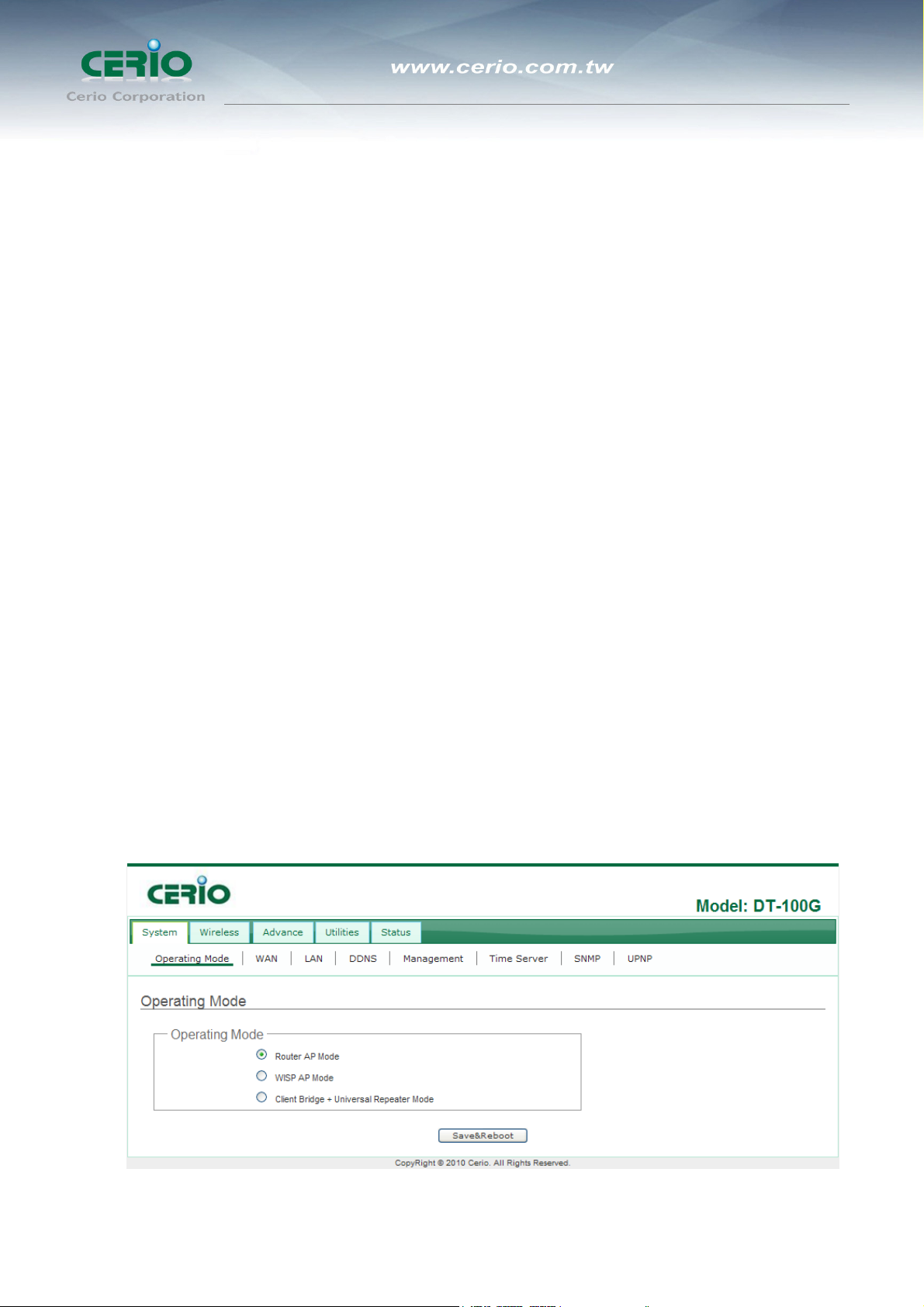
DiToG DT-100G is a multiple mode system which can be configured either as a
wireless gateway or an access point as desired. It also can be used WDS link for
Ethernet network expansion. This section depicts different applications on Router AP
Mode, AP Mode, WDS Mode, WISP Mode, Client Bridge + Universal Repeater
Mode and WISP + AP Mode.
4
User’s Manual
eXtreme High Power Wireless Router
1.2.1
Configuration on Router AP Mode (Gateway + Access Point + WDS)
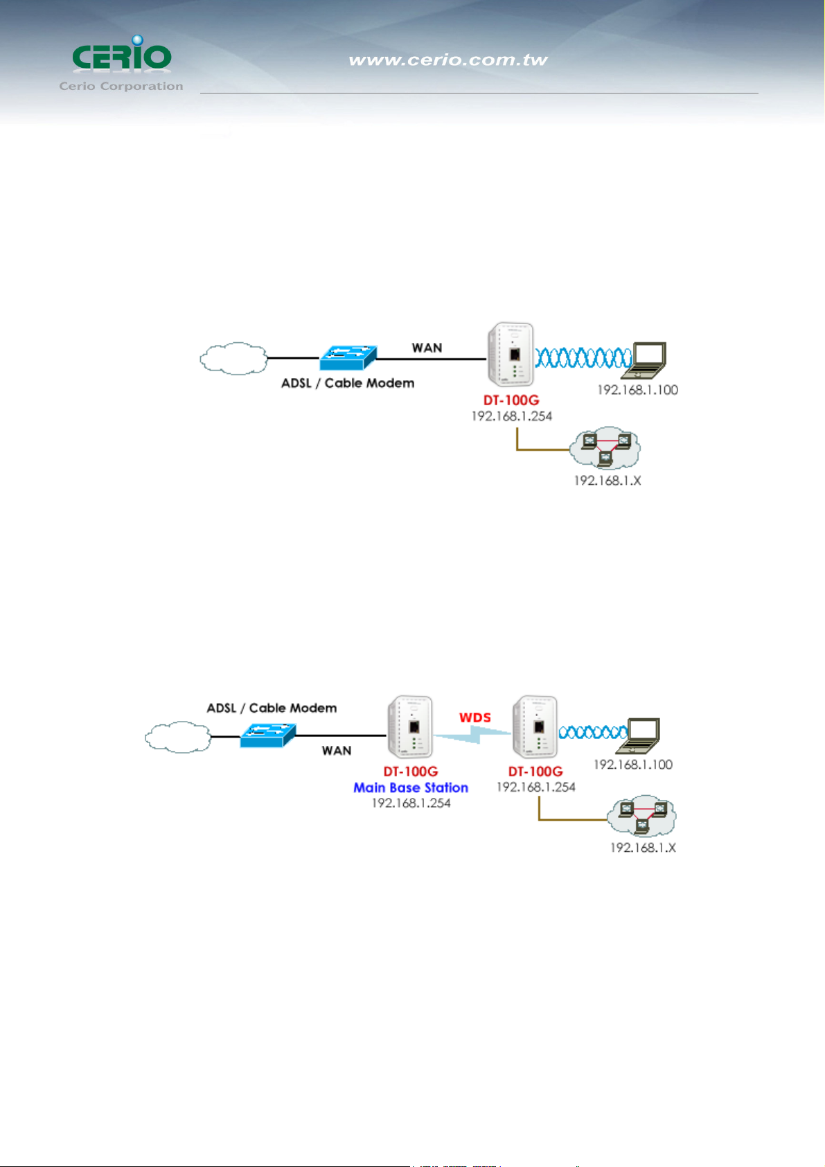
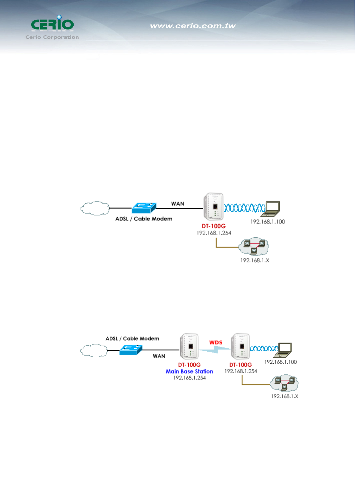
1.2.1.1 Example 1 : Router AP without WDS
It can be deployed as a gateway with wireless Access Point
1.2.1.2 Example 2 : Router AP with WDS
It can be deployed as a gateway with wireless Access Point and provides WDS link for
network extension.
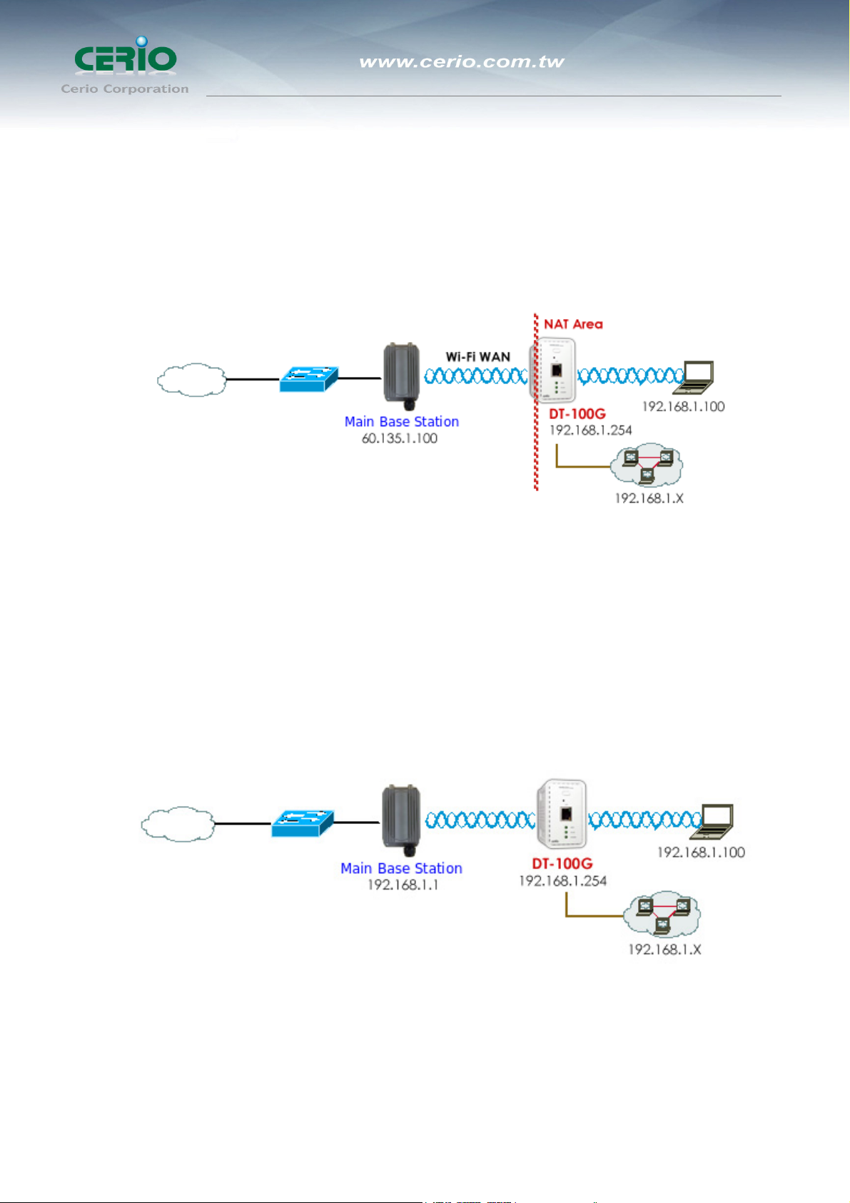
1.2.2 Configuration on WISP AP Mode (Router Client + Access Point)
It can be used as an Wireless Internet Service Provider (WISP) to receive
wireless signal over the last mile, helping WISPs deliver wireless broadband
5
User’s Manual
eXtreme High Power Wireless Router
Internet service to new residential and business customers. In this mode, the
DiToG DT-100G is a gateway with NAT and DHCP Server functions. The wireless
and wired clients of DiToG DT-100G are on the different subnet from Main Base
Station and it accepts wireless connections from client devices.
1.2.3 Configuration in Client Bridge + Universal Repeater Mode
It can be used as an Client Bridge + Universal Repeater to receive wireless signal
over last mile applications, helping WISPs deliver wireless broadband Internet
service to new residential and business customers. In this mode, DiToG DT-100G
is enabled with DHCP Server functions. The wired clients of DiToG DT-100G are
in the same subnet from Main Base Station and it accepts wireless connections
from client devices.
6

eXtreme High Power Wireless Router
1.3 Product Benefit
Key Feature
¾ Operation Modes : Router + A P Mode , WISP + AP Mode,Universal Repeater
Mode.
¾ Maxmum Security with 802.1x, WPA, WPA2(TKIP/AES)
¾ Support Hardware Quickly Wireless Radio ON/ Off Button .
¾ WiFi connection as WAN , in WISP + AP mode , the device run as DHCP server to
assign IP address to clients out of a private IP address pool behind a NAT
¾ Universal Repeater : It extends the range of your wireless network while
simultaneously Allowing wired and wireless clients to access
User’s Manual
Router Feature
¾ DHCP Client、PPPoE Client、Static IP setting function.
¾ Support DHCP Server and Provide Virtual Server. And UPnP functions
¾ PPPOE/PPTP/L2TP functions
¾ Support VPN Pass Throughput ( PPTP , IPSec , L2TP )
¾ MAC Cloning
¾ IEEE802.3 Bridging
¾ Masquerading (NAT)
¾ Proxy DNS ,Dynamic DNS ,NTP Client
¾ Virtual DMZ, Virtual Server (IP / Port Forwarding)
¾ Support IP / MAC Filter
¾ Bandwidth trafic Shaping
Wireless Access Point Feature
¾ In Router + AP Mode ,WDS support to extend wireless coverage by connecting
wirelessly to another , WDS capable wireless device to 8 WDS links
¾ Beacon interval: adjustable to best adapt to the deployment environment
¾ IAPP : to facilitate faster roaming for the stations among different APs nearby
¾ Support Adjustable transmission power : 9 Levels
¾ Wireless Bandwidth Control by Upload and Download setting 256~8192kbps to
control
Authentication/Encryption (Wireless Security)
7

User’s Manual
eXtreme High Power Wireless Router
¾ WEP 64/128/152bits EAP-TLS + Dynamic WEP , EAP-TTLS + Dynamic WEP
PEAP/MSPEAP + Dynamic WEP
¾ WPA-PSK/TKIP,WPA-802.1x/TKIP, 802.11i WPA2-PSK/CCMP/AES, WPA2
(802.1x /CCMP / AES
¾ Setting for TKIP/CCMP/AES key’s refreshing period
¾ Hidden SSID broadcast support
¾ Access Control list (ACL) by MAC Address
Quality of Service
¾ Download and Upload traffic control
¾ Packet classifications via DSCP (Differentiated Services Code Point)
¾ Control Policy by IP/IP Ranges/ MAC/ Layer-7 Application Service
¾ Layer-7 Protocol Support
¾ Traffic Analysis and Statistics
¾ No. of Max. Policy setting : 10
¾ DiffServ/TOS
¾ IEEE 802.11p/COS
¾ IEEE802.11e WMM
¾ QoS Bandwidth Control by Upload and Download setting 8~8192kbps to
control
Parental Control
¾ Blocking Control Policy by IP Range / MAC Group / Port / Layer-7 Protocol
¾ URL Blocking
¾ Web-Based management interface
¾ Remote configuration and management
¾ Remote firmware upgradeable
Management
¾ Software one-button-click to reset back to factory defaults
¾ Utilities for system configuration backup and restoration
¾ UPnP (Universal Plug and Play)
¾ NTP Time Synchronization
¾ Administrative Access : HTTP and HTTPS
¾ Support SNMP v2c/v3
¾ DHCP client
8
¾ UPNP support
¾ Support Event log
¾ Support CLI access via Telnet and SSH
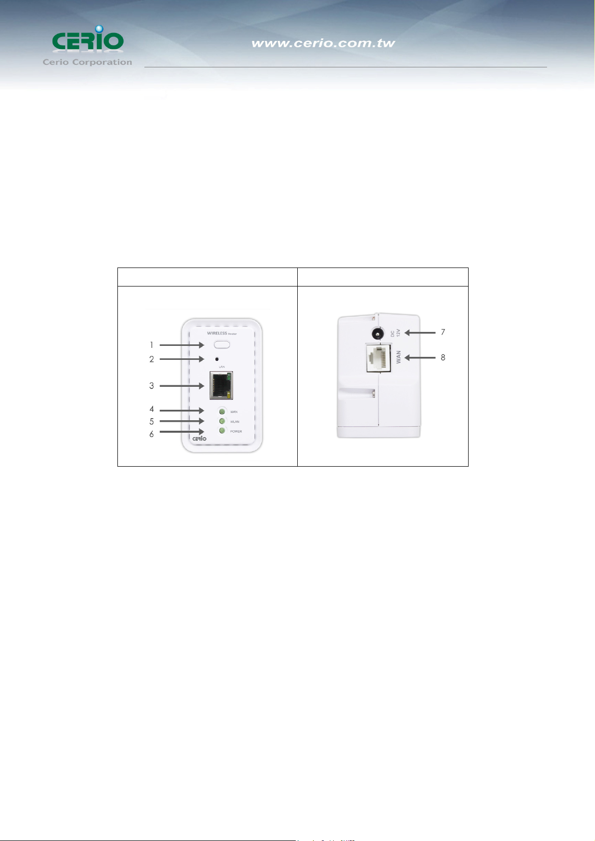
1.4 Panel Function Description
There is several LED indicators and button on the front of the DiToG DT-100G. Please
refer to the definitions below :
Front Panel Up Panel
User’s Manual
eXtreme High Power Wireless Router
1. Wireless Radio On/Off Button: To push the “button” to enable and disable the
Wireless Radio functions.
2. Reset Button: Press and hold the Reset button for more than 10~20 seconds to
reset the system to default configurations.
3. LAN Ethernet port and LAN LED: This port is a Private LAN port that
authentication is not required for clients to access network via this port. and LAN
LED: Link/Act on Port . Green LED ON indicates connection, OFF indicates no
connection, and FLASH.
4. WAN LED : Green LED ON indicates connection, OFF indicates no connection,
and FLASH
5. WLAN: Green LED FLASH indicates Wireless ON, and FLASH quickly indicates
Wireless Transmit quickly.
6. Power: Green LED ON indicates power on, and OFF indicates power off.
7. DC Injector ( 12V ): Attach the power socket here
9

User’s Manual
eXtreme High Power Wireless Router
WAN Ethernet port: This port is for connection to external network switch.
8.
1.5 Hardware Installation Procedures
The procedures to install the “DT-100G eXtreme High Power Wireless Router” please refer
to below .
1. Connecting your computer to the LAN port
Attach one end of the Ethernet cable with RJ-45 connector to your hub, switch or a
computer’s Ethernet port, and the other end to one of the LAN ports of your
“DT-100G eXtreme High Power Wireless Router”.
2. Connecting Cable/ADSL Modem to the WAN port
Connect the Ethernet cable attaching to your Cable/ADSL modem to the WAN port
of your “DT-100G eXtreme High Power Wireless Router”.
3. Connecting the power adapter
Connect the single DC output connector of the power adapter to the power jack on
the side of the “DT-100G eXtreme High Power Wireless Router”. Then plug the
Power Adapter into an AC outlet.
4. Power on the following devices in this order:
Cable/ADSL modem, Router, and PCs.
10

1.6 Software Configuration
DiToG DT-100G supports web-based configuration. Upon the completion of hardware
installation, DiToG DT-100G can be configured through a PC/NB by using its web
browser such as Internet Explorer 6.0 or later.
Default IP Address: 192.168.1.254
Default Subnet Mask: 255.255.255.0
Default Username and Password
Mode Router AP
Management Account Root Account Admin Account
User’s Manual
eXtreme High Power Wireless Router
Username
Password
Mode WISP Mode (by default DHCP server is enabled)
Management Account Root Account Admin Account
Username
Password
Mode Client Bridge + Universal Repeater Mode
Management Account Root Account Admin Account
Username
Password
root admin
default admin
root admin
default admin
root admin
default admin
Configure your PC/NB to connect with DT-100G
Please make sure your network interface card configuration has been completed and
activated on your operating system and connected to one of the LAN port of DT-100G
through Cat.5 or Cat.5e cable. Please make sure the LED on DT-100G is already on
and the LED corresponds with the port which you connected.
By default, the DT-100G will enable DHCP service automatically and distribute an IP
address to your host. the DT-100G default IP is "192.168.1.254". make sure your PCs
are configured to obtain an IP address automatically from the Router by the steps below.
11
User’s Manual
eXtreme High Power Wireless Router
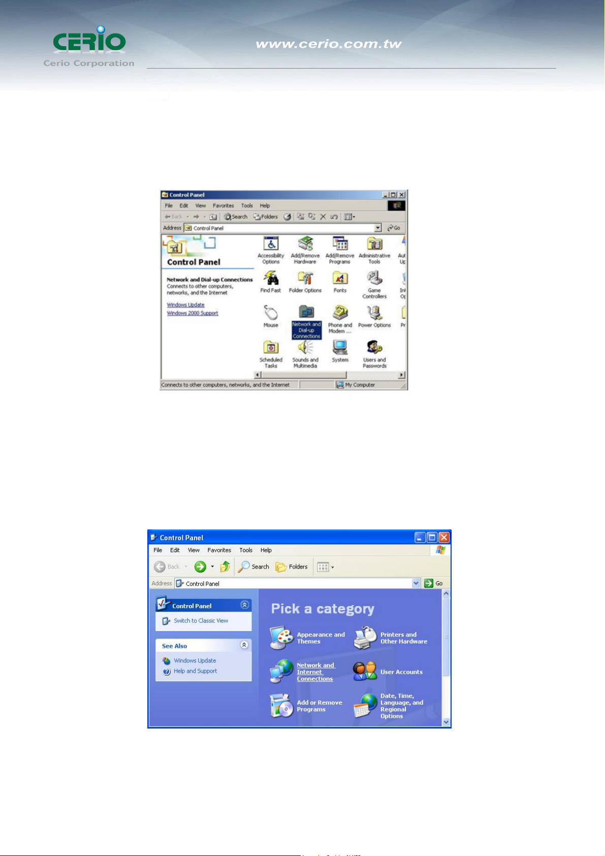
z Windows 2000/XP
Please follow the steps below to setup your computer
5. Go to Start Æ Settings Æ Control Panel
6. Double click the icon Network and Dial-up Connections
7. If you are Windows XP user, please do so.
Go to Start Æ Settings Æ Control Panel
8. Click Network and Internet Connections
12
User’s Manual
eXtreme High Power Wireless Router
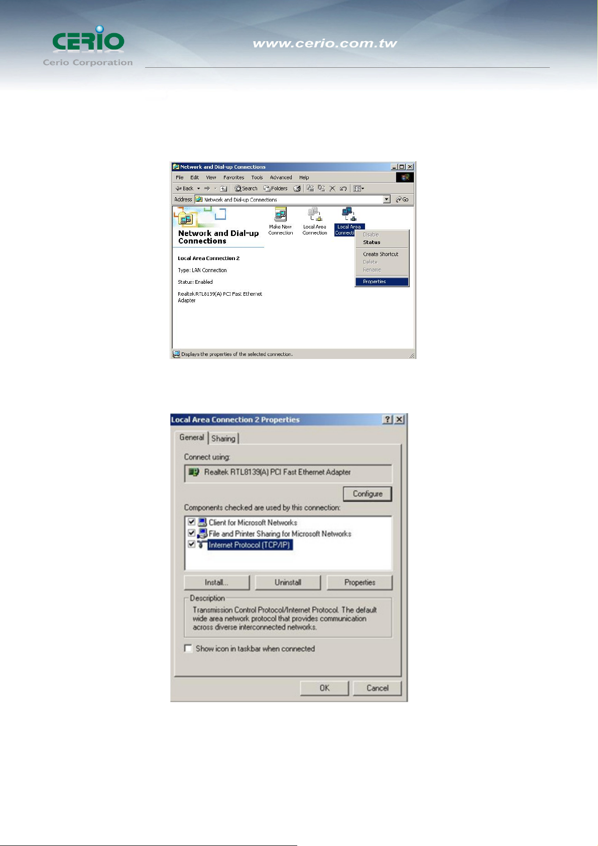
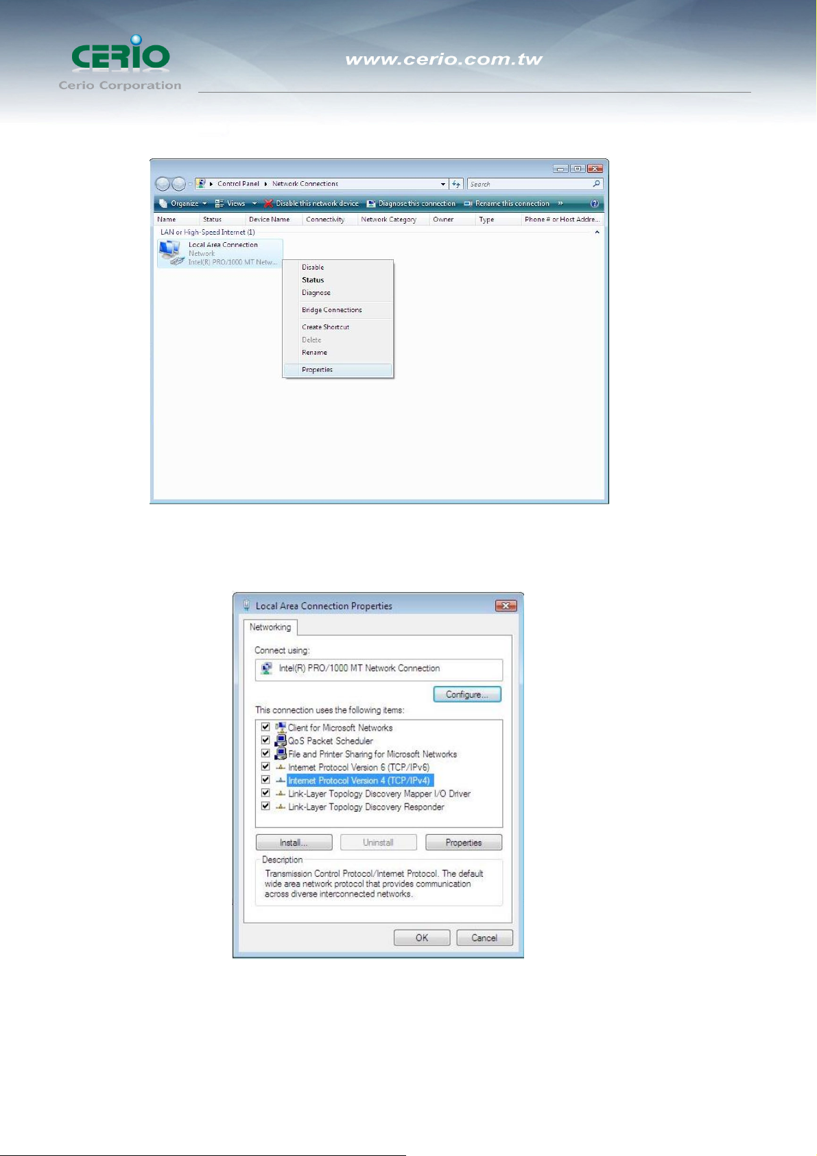
9. Click Network Connections ,Highlight the icon Local Area Connection, right click
your mouse, and click Properties
10. Highlight Internet Protocol (TCP/IP), and then press Properties button
13
User’s Manual
eXtreme High Power Wireless Router
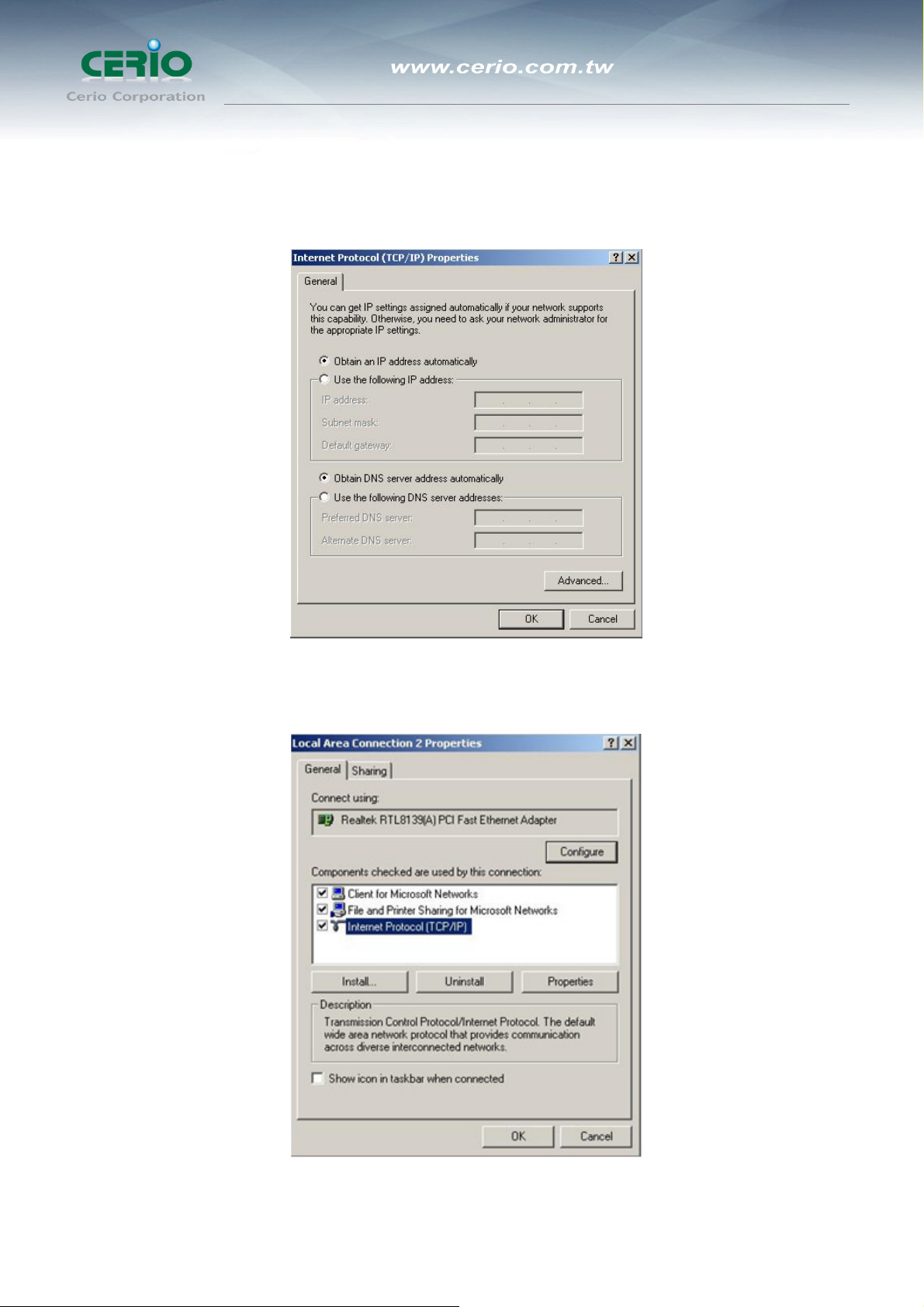
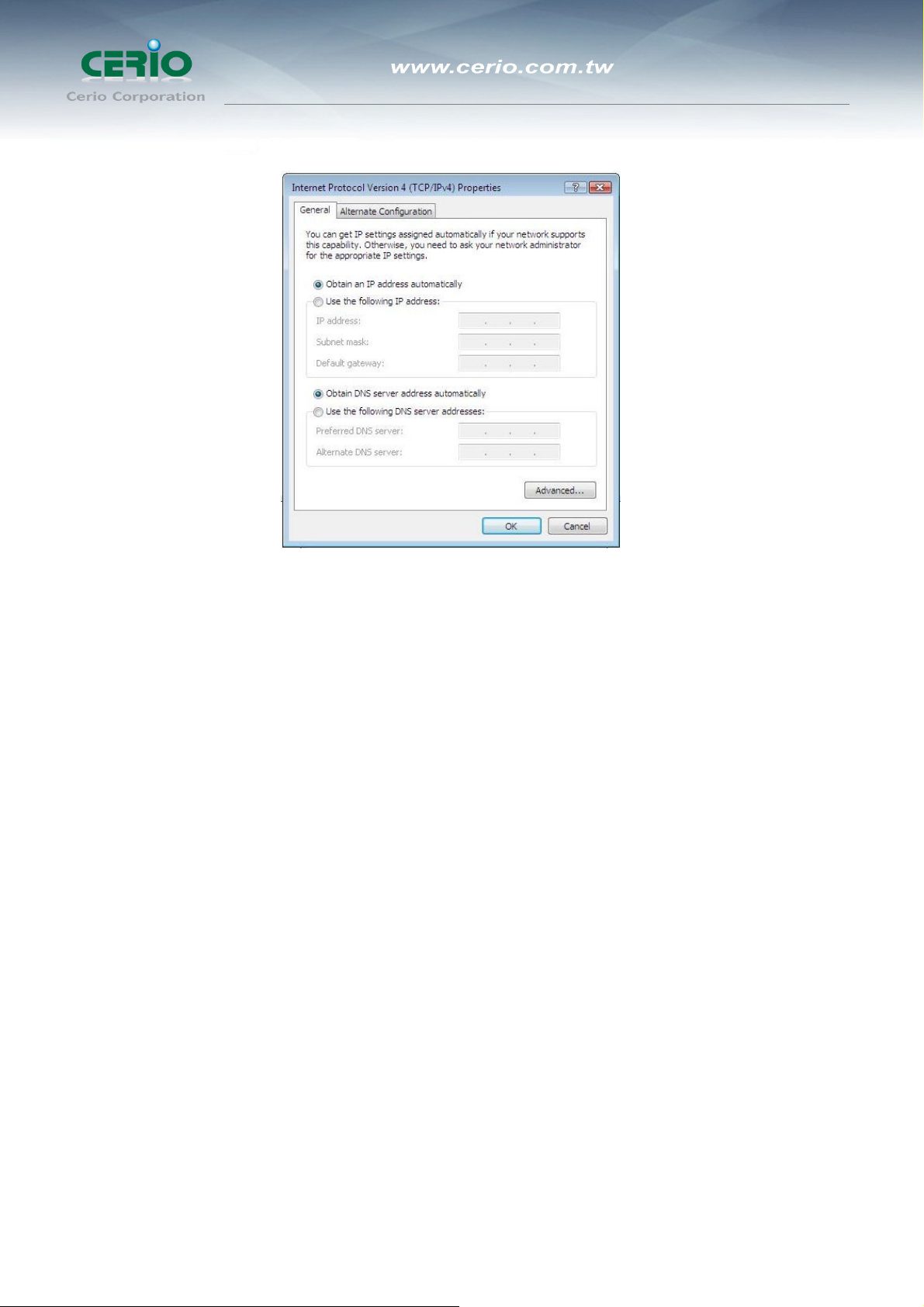
11. Choose Obtain an IP address automatically and Obtain DNS server address
automatically, and then press OK to close the Internet Protocol (TCP/IP) Properties
window
12. Press OK to close the Local Area Connection Properties window
14
User’s Manual
eXtreme High Power Wireless Router
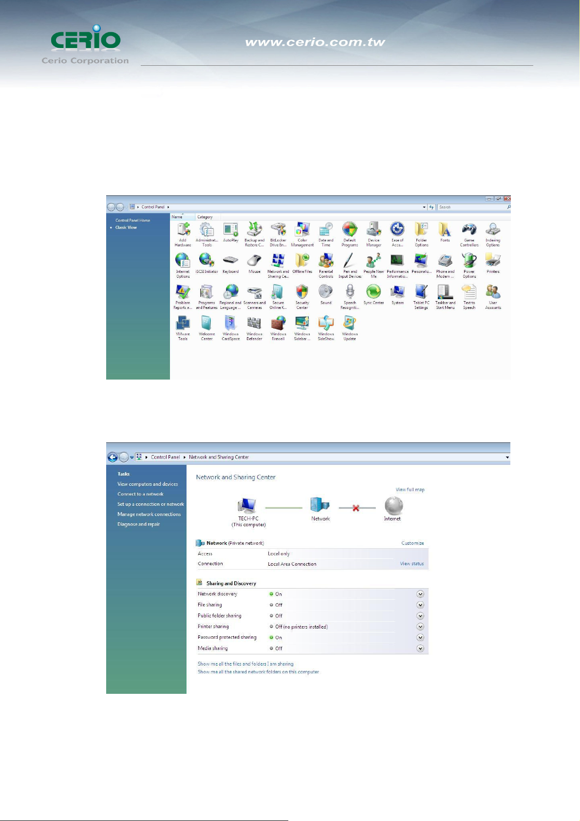
z Windows Vista / Widows 7
Please follow the steps below to setup your computer:
1. Go to Start Æ Settings Æ Control Panel
2. Click Network and Sharing Center
3. Click Manage Network Connections
4. Highlight the icon Local Area Connection, right click your mouse, and click
Properties
15
User’s Manual
eXtreme High Power Wireless Router
5. Highlight Internet Protocol Version 4 (TCP/IP) and then press Properties button
6. Choose Obtain an IP address automatically and Obtain DNS server address
automatically, and then press OK to close the Internet Protocol (TCP/IP)
Properties window
16
User’s Manual
eXtreme High Power Wireless Router
7. Press OK to close the Local Area Connection Properties window
If you finish the operating system TCP/IP setting you can follow the instructions are as
follows to check your IP address:
z Windows98/98se
1. Click Run... on this menu.
2. In the text box that appears type "winipcfg". The "IP address" field shows the IP
address for the default network adapter.
3. If you can't find your adapter IP address, please use the drop-down menu near
the top of the window to browse IP address information for alternate network
adapters.
z Windows 2000/XP/Vista
1. Please make sure that you do have the authority to login as "administrator"
privilege.
2. Click "Start Æ Program Æ Accessories Æ Command Prompt" or "Start Æ
Run...", and then type in "cmd.exe" and press "ENTER" button.
3. It will prompt a "Windows Command-Line" window.
4. Type "ipconfig" after the command of "C:>" and then press "ENTER" button.
5. The "Windows Command-Line" will show you the "Network Interface Card"
information in the window, please take notice of the value of "IP Address" and
17

User’s Manual
eXtreme High Power Wireless Router
"Default Gateway".
6. The value of "Default Gateway" is the IP address of DT-100G.
z Linux / Unix-Like
1. At first please make sure that your NIC are already enable and works property.
2. And be sure you have “root” privilege or you already are one of the member of
“network” group is depending on your Linux distribution or Unix-like type.
3. Please login to your Linux console and make sure your Linux support “DHCP
client” function then after “#” type “ifconfig” or “ifconfig -a” then press “ENTER”
button.
4. It will appear your present network interface card IP address in the console,
please take notice of the value of “IP address” and “Gateway”.
The value of “Gateway” is the IP address of DT-100G
Checking PC’s IP and Connection with the Router
After configuring the TCP/IP protocol, use the ping command to verify if the computer
can communicate with the Router. To execute the ping command, open the DOS
window and ping the IP address of the “DT-100G eXtreme High Power Wireless
Router” at the DOS prompt:
z For Windows 98/Me: Start -> Run. Type command and click OK.
z For Windows 2000/XP: Start -> Run. Type cmd and click OK.
At the DOS prompt, type the following command:
If the Command window returns something similar to the following:
18

User’s Manual
eXtreme High Power Wireless Router
C:\Documents and Settings\admin>ping 192.168.1.254
Pinging 192.168.1.254 with 32 bytes of data:
Reply from 192.168.1.254: bytes=32 time=1ms TTL=64
Reply from 192.168.1.254: bytes=32 time=1ms TTL=64
Reply from 192.168.1.254: bytes=32 time=1ms TTL=64
Reply from 192.168.1.254: bytes=32 time=1ms TTL=64
Ping statistics for 192.168.1.254:
Packets: Sent = 4, Received = 4, Lost = 0 (0%
loss),
Approximate round trip times in milli-seconds:
Minimum = 1ms, Maximum = 1ms, Average = 1ms
Then the connection between the router and your computer has been successfully established.
If the computer fails to connect to the router, the Command window will return the following:
C:\Documents and Settings\admin>ping 192.168.1.254
Pinging 192.168.1.254 with 32 bytes of data:
Request timed out.
Request timed out.
Request timed out.
Request timed out.
Ping statistics for 192.168.1.254:
Packets: Sent = 4, Received = 0, Lost = 4 (100% loss)
Verify your computer's network settings are correct and check the cable connection
between the router and the computer. In order to make the whole network operate
successfully, it is necessary to configure the DT-100G through your computer has a WEB
browser installed. Please follow up the steps listed below.
Login to DT-100G
Now, we will going to setup DT-100G through your WEB browser that installed on your
PC/NB, please do as follow:
19
User’s Manual
eXtreme High Power Wireless Router
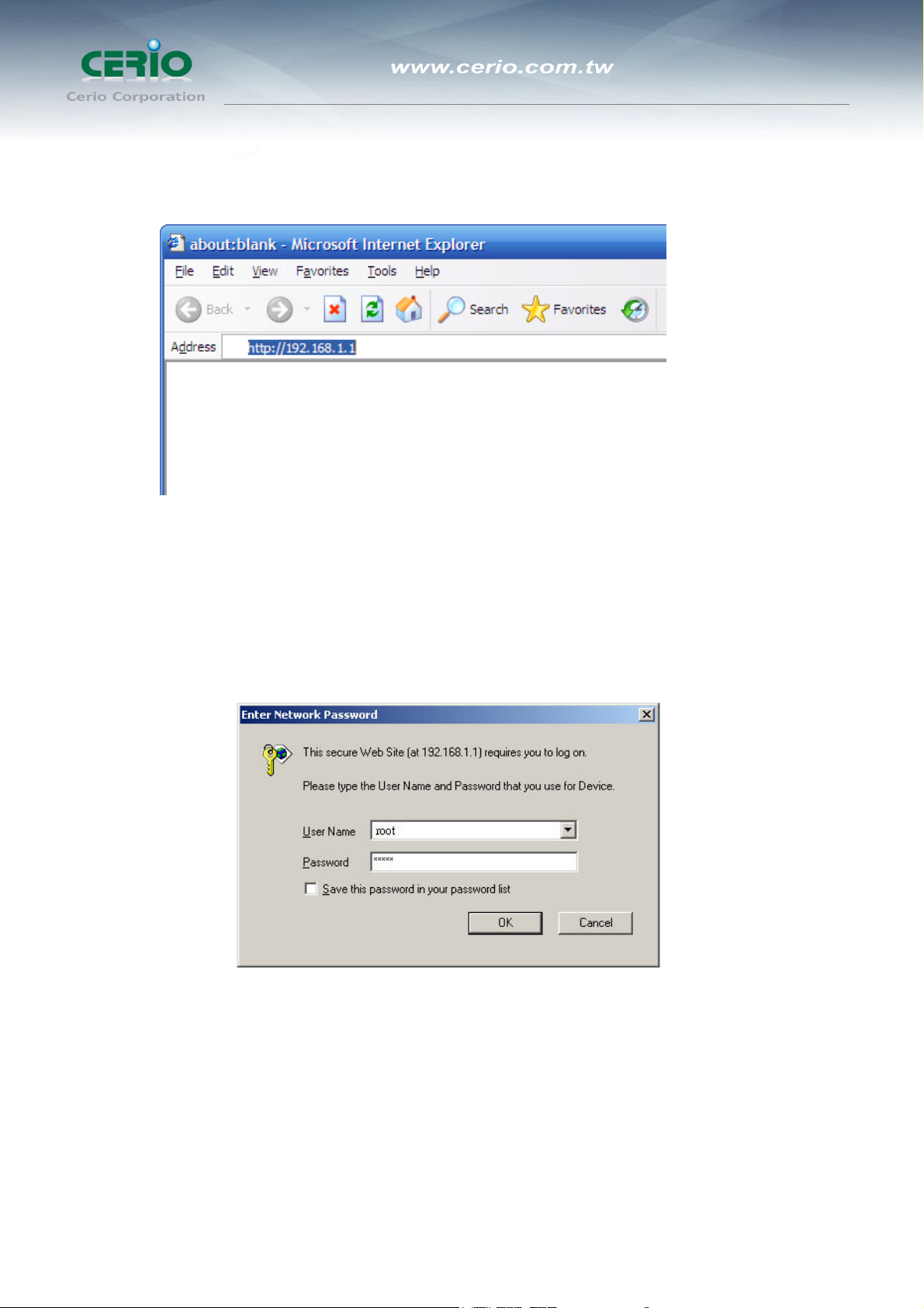
1. Startup Internet Explorer and enter http://192.168.1.254, then press Enter
2. You will enter the user name and password. The default user name is “root” ,
password is “default”, too. You can’t modify you user name but can modify your
password. You need modify you password when you successfully login, incase
anyone else may invade your Internet illegally.
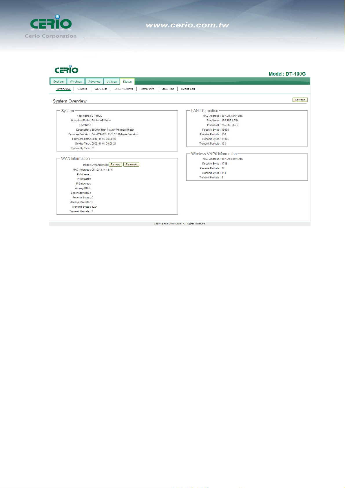
3. After successful login, in the home page of the DT-100G, the left navigation bar
shows the main options to configure the system. In the right navigation screen is the
summary of system status for viewing the configurations.
20
User’s Manual
eXtreme High Power Wireless Router
System Overview page will appear after successful login.
21

User’s Manual
eXtreme High Power Wireless Router
Router AP Mode Configuration
When Router AP mode is chosen, the system can be configured as a Router with
Access Point and WDS function. This section provides detailed explanation for
users to configure in the Router AP mode with help of illustrations. In the Router
AP mode, functions listed in the table below are also available from the
Web-based GUI interface.
22
eXtreme High Power Wireless Router
2 Router AP Mode Configuration
2.1 External Network Connection
2.1.1 Network Requirement
It can be used as an Router AP with WDS function. In this mode, DiToG DT-100G
is a gateway enabled with NAT and DHCP Server functions. The wireless clients
connected to Internet.
Example 1 : Router AP without WDS
It can be deployed as a gateway with wireless Access Point
User’s Manual
Example 2 : Router AP with WDS
It can be deployed as a gateway with wireless Access Point and provides WDS link for network
extension.
2.1.2 Configure WAN Setup
It can be used as an Router AP with WDS function. In this mode, DiToG DT-100G
is a gateway enabled with NAT and DHCP Server functions. The wireless clients
connected to Internet.
There are three connection types for the WAN port : Static IP, Dynamic IP, PPPoE .
23
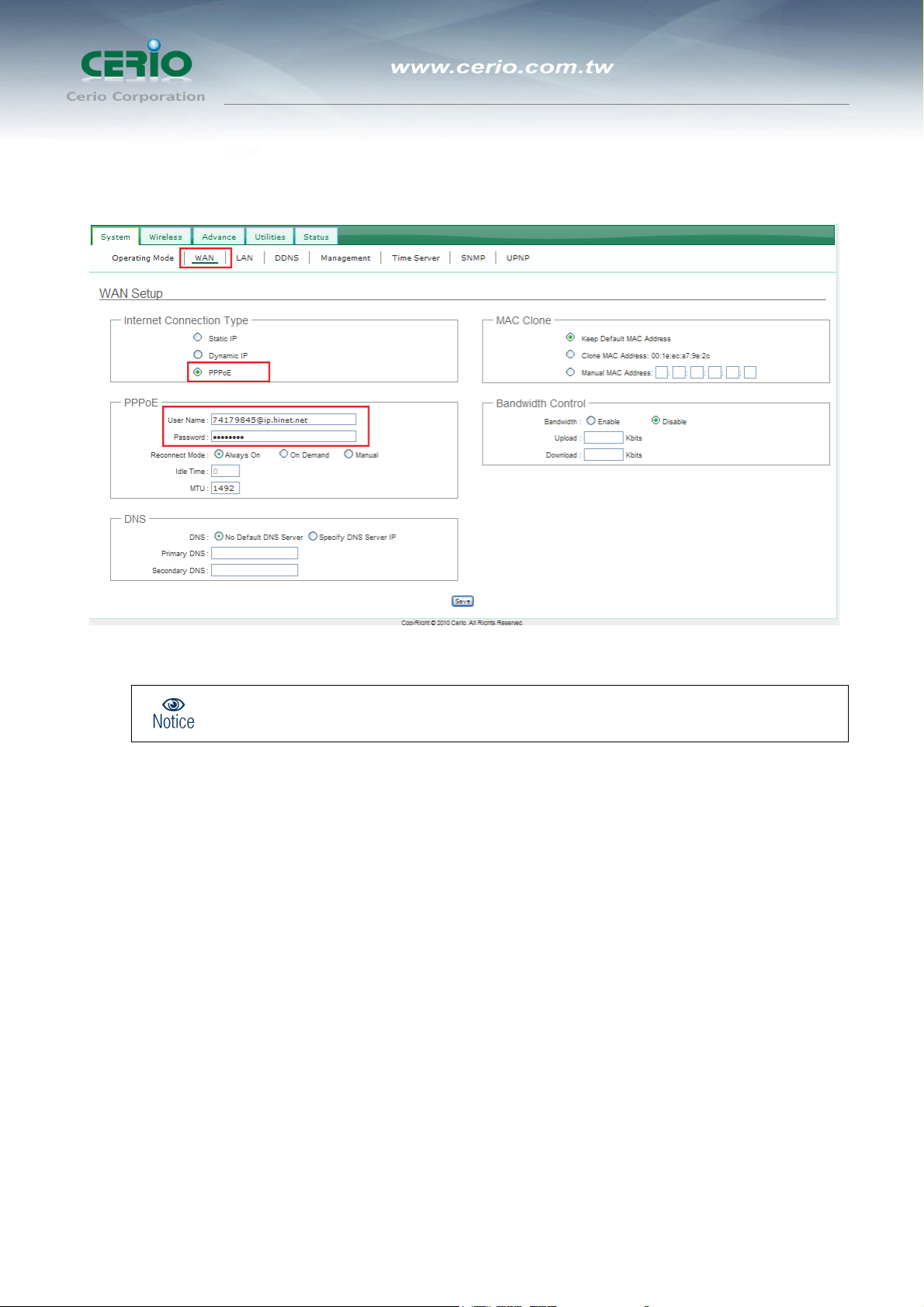
Please click on System -> WAN and follow the below setting.
User’s Manual
eXtreme High Power Wireless Router
Notice: In Router AP mode, the WAN Port is the wired interface.
Mode : By default, it’s “Static IP”. Check “Static IP”, “Dynamic IP”, “PPPoE” to set up system WAN IP.
Î Static IP : Users can manually setup the WAN IP address with a static IP provided by WISP.
9 IP Address : The IP address of the WAN port; default IP address is 192.168.1.254
9 IP Netmask : The Subnet mask of the WAN port; default Netmask is 255.255.255.0
9 IP Gateway : The default gateway of the WAN port; default Gateway is 192.168.1.1
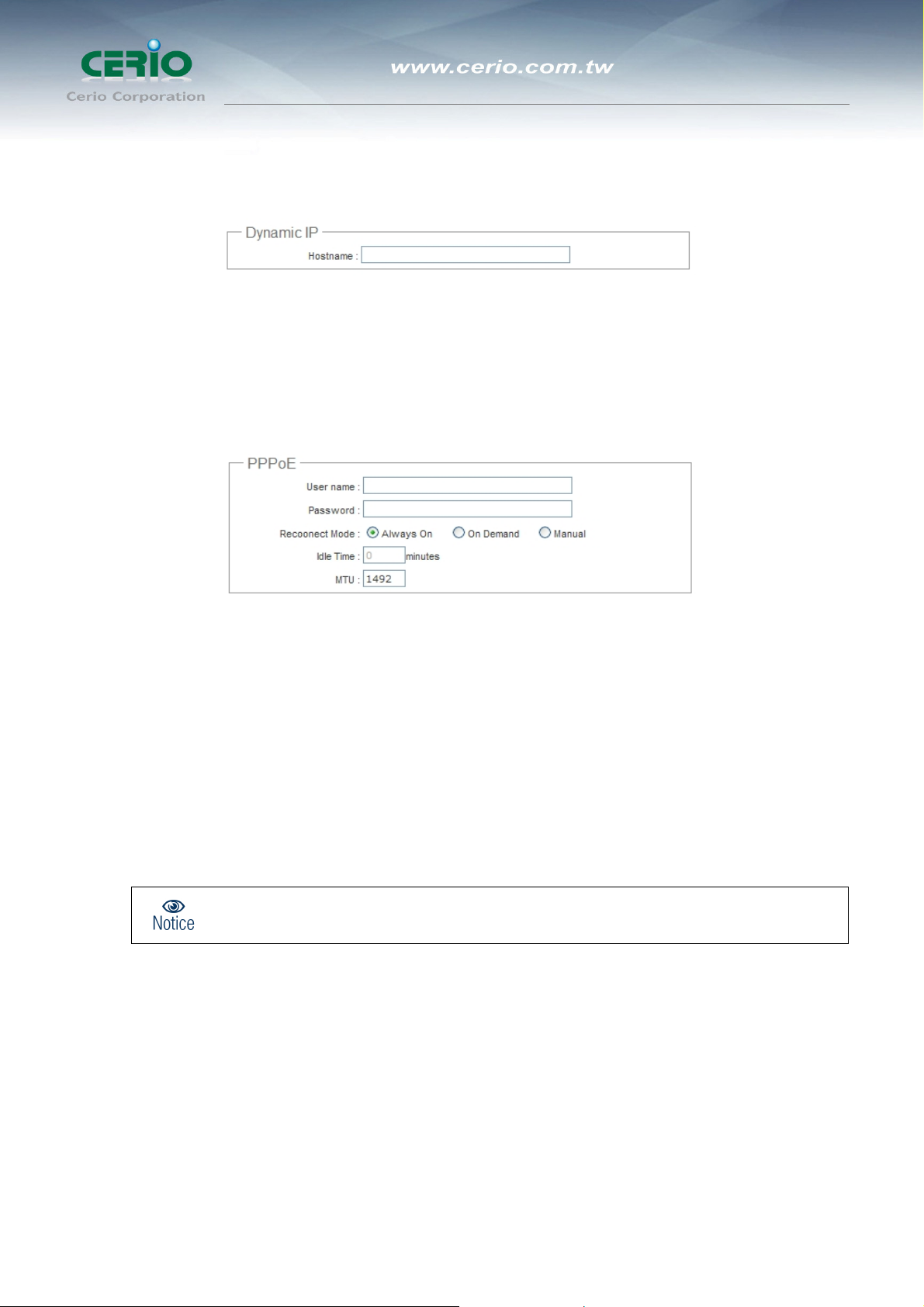
Î Dynamic IP : Please consult with WISP for correct wireless settings to associate with WISP AP before a
dynamic IP, along with related IP settings including DNS can be available from DHCP server. If IP
Address is not assigned, please double check with your wireless settings and ensure successful
association. Also, you may go to “WAN Information” in the Overview page to click Release button to
24
eXtreme High Power Wireless Router
release IP address and click Renew button to renew IP address again.
9 Hostname : The Hostname of the WAN port
Î PPPoE : To create wireless PPPoE WAN connection to a PPPoE server in network.
User’s Manual
9 User Name : Enter User Name for PPPoE connection
9 Password : Enter Password for PPPoE connection
9 Reconnect Mode :
• Always on – A connection to Internet is always maintained.
On Demand – A connection to Internet is made as needed.
Notice: When Time Server is enabled at the “On Demand” mode, the “Reconnect Mode”
will turn out “Always on”.
• Manual – Click the “Connect” button on “WAN Information” in the Overview page to connect to
the Internet.
9 Idle Time : Time to last before disconnecting PPPoE session when it is idle. Enter preferred Idle
Time in minutes. Default is “0”, indicates disabled. When Idle time is disabled, the “Reconnect
Mode” will turn out “Always on”
25
User’s Manual
eXtreme High Power Wireless Router
9 MTU : By default, it’s 1492 bytes. MTU stands for Maximum Transmission Unit. Consult with WISP
for a correct MTU setting.
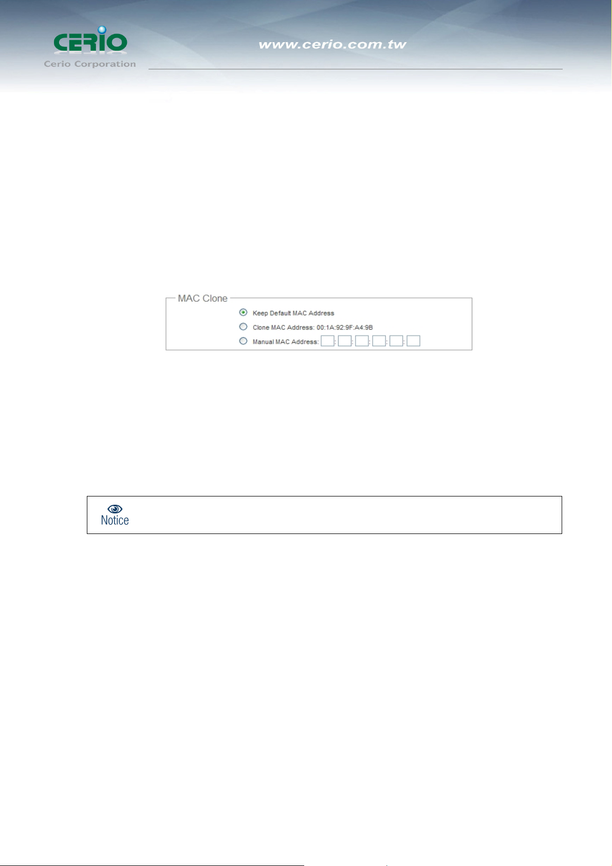
MAC Clone : The MAC address is a 12-digit HEX code uniquely assigned to hardware as identification. Some
ISPs require you to register a MAC address in order to access to Internet. If not, you could use default MAC or
clone MAC from a PC.
Î Keep Default MAC Address : Keep the default MAC address of WAN port on the system.
Clone MAC Address : If you want to clone the MAC address of the PC, then click the Clone MAC
Address button. The system will automatically detect your PC's MAC address.
Notice: The Clone MAC Address field will display MAC address of the PC connected to
system. Click “Save” button can make clone MAC effective.
Î Manual MAC Address : Enter the MAC address registered with your ISP.
Click Save button to save your changes. Click Reboot button to activate your changes
2.1.3 Configure DDNS Setup
Dynamic DNS allows you to map domain name to dynamic IP address.
26

User’s Manual
eXtreme High Power Wireless Router
Please click on System -> DDNS Setup and follow the below setting.
Enabled: By default, it’s “Disable”. The mapping domain name won’t change when dynamic IP changes. The
beauty of it is no need to remember the dynamic WAP IP while accessing to it.
Service Provider: Select the preferred Service Provider from the drop-down list including dyndns, dhs, ods
and tzo
Hostname: Host Name that you register to Dynamic-DNS service and export.
User Name & Password: User Name and Password are used to login DDNS service.
Click Save button to save your changes. Click Reboot button to activate your changes
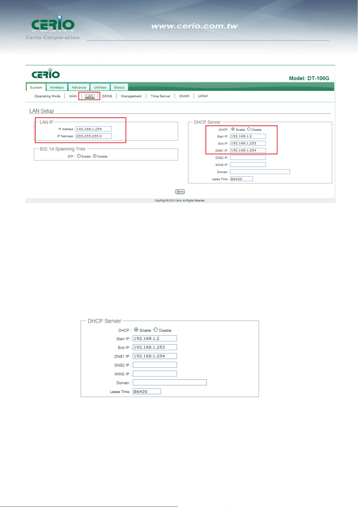
2.1.4 Configure LAN Setup
Here are the instructions for how to setup the local IP Address and Netmask.
Please click on System -> LAN and follow the below setting.
27
User’s Manual
eXtreme High Power Wireless Router
LAN IP : The administrator can manually setup the LAN IP address.
Î IP Address : The IP address of the LAN port; default IP address is 192.168.1.254
Î IP Netmask : The Subnet mask of the LAN port; default Netmask is 255.255.255.0
DHCP Setup : Devices connected to the system can obtain an IP address automatically when this service is
enabled.
Î DHCP : Check Enable button to activate this function or Disable to deactivate this service.
Î Start IP / End IP: Specify the range of IP addresses to be used by the DHCP server when assigning IP
address to clients. The default range IP address is 192.168.1.2 to 192.168.1.253, the netmask is
255.255.255.0
28
User’s Manual
eXtreme High Power Wireless Router
Î DNS1 IP : The default DNS 1 IP address 192.168.1.254 .
Î DNS2 IP : Enter IP address of the second DNS server; this is optional.
Î WINS IP : Enter IP address of the Windows Internet Name Service (WINS) server; this is optional.
Î Domain : Enter the domain name for this network.
Lease Time : The IP addresses given out by the DHCP server will only be valid for the duration
specified by the lease time. Increasing the time ensure client operation without interruptions, but could
introduce potential conflicts. Lowering the lease time will avoid potential address conflicts, but might
cause more interruptions to the client while it will acquire new IP addresses from the DHCP server.
Default is 86400 seconds
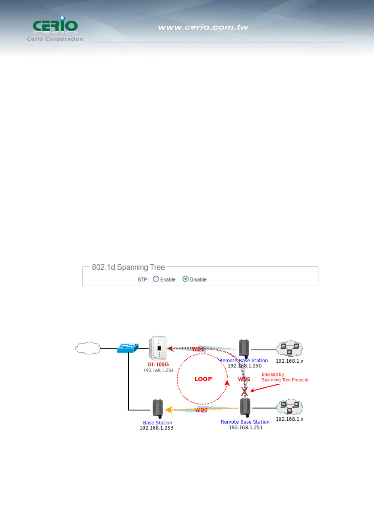
802.1d Spanning Tree
The spanning tree network protocol provides a loop free topology for a bridged LAN between LAN
interface and 8 WDS interfaces from wds0 to wds7. The Spanning Tree Protocol, which is also
referred to as STP, is defined in the IEEE Standard 802.1d.
Click Save button to save your changes. Click Reboot button to activate your changes
29
2.2 Wireless LAN Network Creation
The administrator can change the data transmission, channel and output power
settings for the system. Please click on Wireless -> General Setup and follow the
below setting.
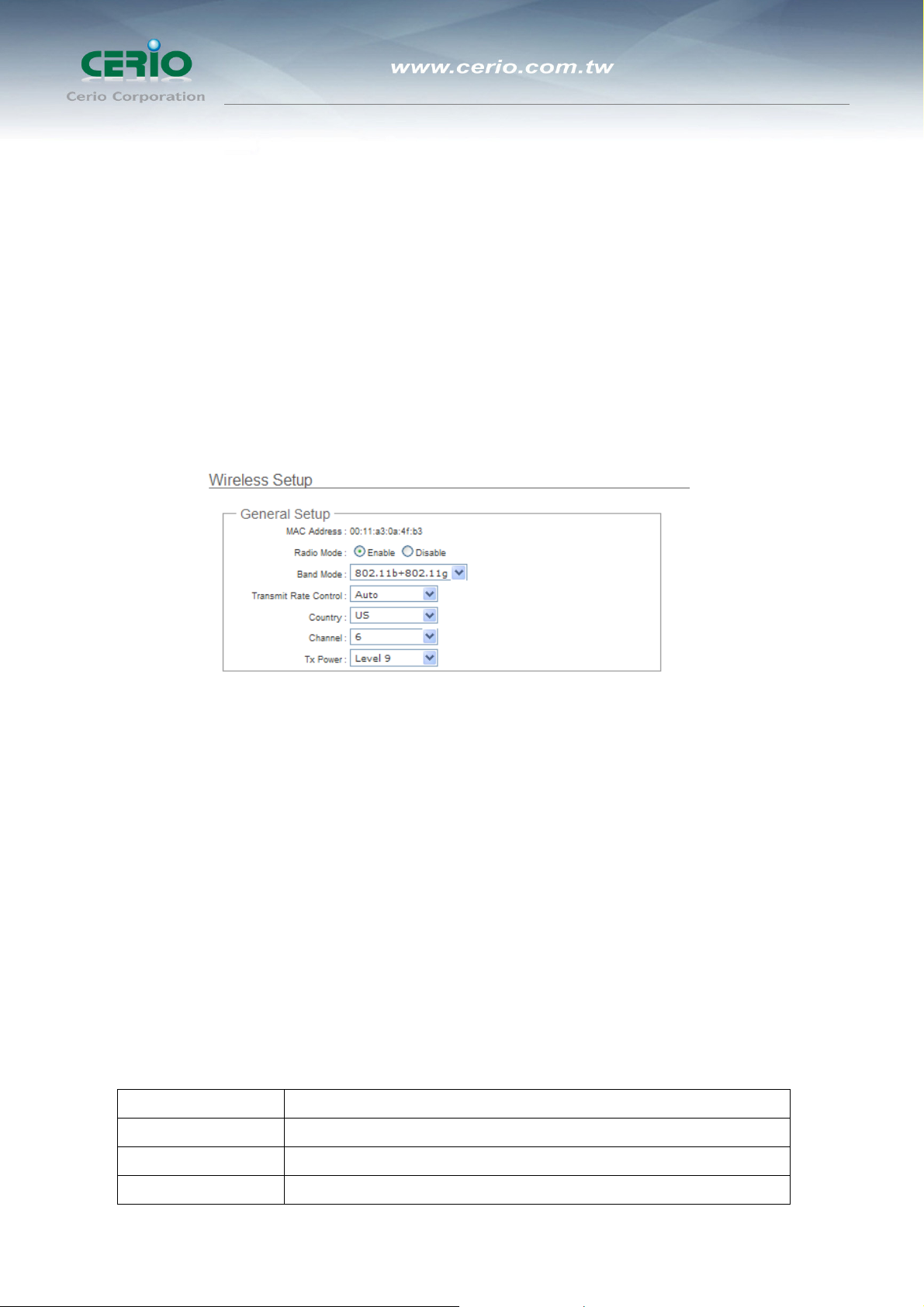
2.2.1 Wireless General Setup
The administrator can change the data transmission, channel and output power
settings for the system. Please click on Wireless -> General Setup and follow the
below setting.
User’s Manual
eXtreme High Power Wireless Router
MAC Address : The MAC address of the Wireless interface is displayed here.
Radio Mode : The Enable is Wireless Radio to ON , Disable is Wireless Radio to OFF , the default is enable
to ON , The enable or disable will follow hardware Radio control button to auto change.
Band Mode : Select an appropriate wireless band; bands available are 801.11b or 802.11g mode.
Transmit Rate Control : Select the desired rate from the drop-down list; the options are auto or ranging from
1 to 54Mbps for 802.11g and 802.11b/g modes, or 1 to 11Mbps for 802.11b mode.
Country : Select the desired country code from the drop-down list; the options are US, ETSI, JP and NONE.
Channel : The channel range will be changed by selecting different country code.
Country Channel
US
ETSI
JP
Auto, 1~11
Auto, 1~13
Auto, 1~13
30

User’s Manual
eXtreme High Power Wireless Router
Tx Power : You can adjust the output power of the system to get the appropriate coverage for your wireless
network. Specify digit numbers between 1 to 100 (the unit is %) for your environment. If you are not sure
which setting to choose, then keep the default setting, 100%.
Change these settings as described here and click Save button to save your changes.
Click Reboot button to activate your changes. The items in this page is for AP's RF
general settings and will be applied to all VAPs.
2.2.2 Wireless Advanced Setup
To achieve optimal wireless performance, it is necessary to tweak advance setting per requirements properly, not
necessary higher the better or lower.
The administrator can change the RTS threshold and fragmentation threshold settings for the system. Please click
on Wireless -> Advanced Setup and follow the below setting.
¾ Slot Time: Enter the desired slot time for the AP.
31

User’s Manual
eXtreme High Power Wireless Router
¾ ACK Timeout: The time interval for waiting the “ACK nowledgment frame”. If the ACK is not
received within that timeout period then the packet will be re-transmitted. Higher ACK Timeout will
decrease the packet lost, but the throughput will be growing worse.
¾ CTS Timeout: Enter the desired CTS timeout for the AP.
Notice: Slot Time and ACK/CTS Timeout settings for long distance links. It is important to
change the value to find the optimal setting. A value too low will give very low throughput,
A high value may slowdown the link.
¾ RSSI Threshold: RSSI Threshold can be used to control the level of noise received by the device.
¾ Beacon Interval: Enter a value between 10 and 5000 msec. The default value is 100 milliseconds.
The entered time means how often the beacon signal transmission between the access point and
the wireless network.
¾ DTIM Interval: Input the DTIM Interval that is generated within the periodic beacon at a specified
frequency. Higher DTIM will let the wireless client save energy more, but the throughput will be
growing worse.
¾ Fragment Threshold: The value specifies the maximum size of packet allowed before data is
fragmented into multiple packets. Please use this value to tune the wireless connection if lots of
retransmission happens. Enter a value ranging from 256 to 2346.
¾ RTS Threshold: Tuning the Request to Send, RTS threshold will help the system control its access
to medium and alleviate the hidden node problem. Enter a value ranging from 1 to 2346.
¾ Short Preamble: The short preamble provides 56-bit Synchronization field to improve WLAN
transmission efficiency. Check Enable button for using Short Preamble, and Disable for using the
Long Preamble, 128-bit Synchronization field, option.
¾ Tx Burst: Click Enable button to activated Tx Burst, and Disable to unactivated Tx Burst.
¾ 802.11g Protection Mode: Click Enable button to activated 802.11g Protection Mode, and Disable
to unactivated 802.11g Protection Mode.
Change these settings as described here and click Save button to save your changes. Click
Reboot button to activate your changes. The items in this page is for Router AP's RF general
32

User’s Manual
eXtreme High Power Wireless Router
settings and will be applied to all VAPs.
2.2.3 Create Virtual AP (VAP)
The DiToG DT-100G support broadcasting multiple SSIDs, allowing the creation of Virtual Access Points,
partitioning a single physical access point into 8 logical access points, each of which can have a different set of
security
and network settings.
2.2.3.1
The administrator can view all of the Virtual AP's settings via this page.
Please click on Wireless -> Virtual AP Setup and the Virtual AP Overview Page appears.
Virtual AP Overview
VAP : Indicate the system's Virtual AP.
ESSID : Indicate the ESSID of the respective Virtual AP.
Status : Indicate the Status of the respective Virtual AP. The Primary AP always on.
Security Type : Indicate an used security type of the respective Virtual AP.
MAC Filter : Indicate an used MAC filter of the respective Virtual AP.
MAC Filter Setup : Click “Setup” Hyperlink for configuring Virtual AP's Access Control List.
Edit : Click “Edit” Hyperlink to configure Virtual AP's settings, including security type and MAC
Filter.
33

User’s Manual
eXtreme High Power Wireless Router
2.2.3.2
For each Virtual AP, administrators can configure SSID,SSID broadcasting, Maximum number of client
associations, security type settings.
Click Edit button on the Edit column, and then a Virtual AP setup page appears.
Virtual AP Setup
¾ ESSID: Extended Service Set ID indicates the SSID which the clients used to connect to the VAP.
ESSID will determine the service type of a client which is assigned to the specified VAP.
¾ Hidden SSID: Select this option to enable the SSID to broadcast in your network. When configuring
the network, it is suggested to enable this function but disable it when the configuration is complete.
With this enabled, someone could easily obtain the SSID information with the site survey software
and get unauthorized access to a private network. With this disabled, network security is enhanced
and can prevent the SSID from begin seen on networked.
¾ Client Isolation: Select Enable, all clients will be isolated from each other, that means all clients
can not reach to other clients.
¾ WMM: Select Enable, the packets with QoS WMM will has higher priority.
¾ IAPP Support: Inter Access-Point Protocol is designed for the enforcement of unique association
throughout a ESS(Extended Service Set) and for secure exchange of station's security context
between current access point (AP) and new AP during hand off period.
34

User’s Manual
eXtreme High Power Wireless Router
Notice: IAPP only used on WPA-PSK and WPA2-PSK security type. Only one of VAPs
can be enabled.
¾ Maximum Clients: Enter maximum number of clients to a desired number. For example, while the
number of client is set to 32, only 32 clients are allowed to connect with this VAP.
¾ Bandwidth Control : Click “Enable” to activate function, and click “Disable” to deactivate
function
Î Upload / Download : Specify the bandwidth in kilobit per second (Kbps). Enter a number
between 256 to 8192. default upload is 8192 Kbps, download is 8192 Kbps.
¾ Security Type: Select the desired security type from the drop-down list; the options are WEP,
WPA-PSK, WPA2-PSK, WPA-Enterprise, WPA2-Enterprise and WEP 802.1X.
1. Disable: Data are unencrypted during transmission when this option is selected.
2. WEP
WEP, Wired Equivalent Privacy, is a data encryption mechanism based on a 64-bit, 128-bit or
152-bit shared key. Select WEP as the security type from the drop down list as desired.
z Key Length: The key size of WEP encryption can be 64bit, 128bit or 152bit.
z WEP auth method: You can select the appropriate value: Open system (If enabling this mode, there is
35

User’s Manual
eXtreme High Power Wireless Router
no need authentication to access AP or Wireless NIC) or Shared (Only those who are sharing the same
key with the AP can connect with it).
z Key Index: You can select the Key which you want to use. Other wireless station must have the same
key value to connect with DT-100G, 4 different WEP keys can be configured at the same time, but only
one is used. Effective key is set with a choice of WEP Key 1, 2, 3 or 4.
z WEP Key #: You can chose either HEX or ASCII for your WEP key value, for 64bit encryption strength
can use 10 digits for HEX (0~9, a~f and A-F) or 5 digits for ASCII (0~9, a~z and A~Z), for 128bit
encryption strength can use 26 digits for HEX (0~9, a~f and A-F) or 13 digits for ASCII (0~9, a~z and
A~Z), for 152bit encryption strength can use 32 digits for HEX (0~9, a~f and A-F) or 16 digits for ASCII
(0~9, a~z and A~Z)
z WPA-PSK (or WPA2-PSK): WPA-PSK is short for W-Fi Protected Access-Pre-Shared Key. WPA-SPK
uses the same encryption way with WPA, and the only difference between them is that WPA-PSK
recreates a simple shared key, instead of using the user’s certification.
z Cipher Suite:
You can chose use AES or TKIP with your WPA / WPA2 encryption method,
AES is short for “Advanced Encryption Standard”, The AES cipher is specified as a number of
repetitions of transformation rounds that convert the input plaintext into the final output of ciphertext.
Each round consists of several processing steps, including one that depends on the encryption key. A
set of reverse rounds are applied to transform ciphertext back into the original plaintext using the same
encryption key.
TKIP is short for “Temporal Key Integrity Protocol”, TKIP scrambles the keys using a hashing
algorithm and, by adding an integrity-checking feature, ensures that the keys haven’t been tampered
with.
z Group Key Update Period:
This time interval for re-keying GTK (broadcast/multicast encryption keys) in seconds. Enter the
time-length required; the default time is 600 seconds.
36

z Master Key Update Period:
This time interval for re-keying GMK (master key used internally to generate GTKs) in seconds. Enter
the time-length required; the default time is 83400 seconds.
z EAP Reauth Period:
This time interval for re- authentication in seconds. Enter the time-length required; the default time is
3600 seconds; 0 = disable re-authentication.
z Key Type:
Check on the respected button to enable either ASCII or HEX format for the Pre-shared Key.
z Pre-Shared Key:
Enter the information for pre-shared key; the format of the information shall according to the key type
selected. Pre-shared key can be either entered as a 256-bit secret in 64 HEX digits format, or 8 to 63
ASCII characters.
3. WPA-Enterprise (or WPA2-Enterprise) General Setting
User’s Manual
eXtreme High Power Wireless Router
The RADIUS authentication and encryption will be both enabled if this selected.
4. WPA-Enterprise (or WPA2-Enterprise) General Setting
37

z Cipher Suite:
You can chose use AES or TKIP with your WPA / WPA2 encryption method,
AES is short for “Advanced Encryption Standard”, The AES cipher is specified as a number of
repetitions of transformation rounds that convert the input plaintext into the final output of ciphertext.
Each round consists of several processing steps, including one that depends on the encryption key. A
set of reverse rounds are applied to transform ciphertext back into the original plaintext using the same
encryption key.
User’s Manual
eXtreme High Power Wireless Router
TKIP is short for “Temporal Key Integrity Protocol”, TKIP scrambles the keys using a hashing
algorithm and, by adding an integrity-checking feature, ensures that the keys haven’t been tampered
with.
z Group Key Update Period:
This time interval for re-keying GTK (broadcast/multicast encryption keys) in seconds. Enter the
time-length required; the default time is 600 seconds.
z Master Key Update Period:
This time interval for re-keying GMK (master key used internally to generate GTKs) in seconds. Enter
the time-length required; the default time is 83400 seconds.
z EAP Reauth Period:
This time interval for re- authentication in seconds. Enter the time-length required; the default time is
3600 seconds; 0 = disable re-authentication.
5. Authentication RADIUS Server Settings
z Authentication Server: Enter the IP address of the Authentication RADIUS server.
z Port: The port number used by Authentication RADIUS server. Use the default 1812 or enter port
number specified.
38

User’s Manual
eXtreme High Power Wireless Router
z Shared secret: The secret key for system to communicate with Authentication RADIUS server. Support
1 to 64 characters.
z Accounting Server: Check on the respected button to enable either Enable or Disable accounting
RADIUS server.
6. Accounting Server Settings
z Accounting Server: Enter the IP address of the Accounting RADIUS server.
z Port: The port number used by Accounting RADIUS server. Use the default 1813 or enter port number
specified.
z Shared Secret: The secret key for system to communicate with Accounting RADIUS server. Support 1
to 64 characters.
7. Secondary Authentication RADIUS Server
z Authentication Server: Enter the IP address of the Authentication RADIUS server.
z Port: The port number used by Authentication RADIUS server. Use the default 1812 or enter port
number specified.
z Shared secret: The secret key for system to communicate with Authentication RADIUS server. Support
1 to 64 characters.
z Accounting Server: Check on the respected button to enable either Enable or Disable accounting
RADIUS server.
8. (Secondary) Accounting Server Settings
z Accounting Server: Enter the IP address of the Accounting RADIUS server.
39

User’s Manual
eXtreme High Power Wireless Router
z Port: The port number used by Accounting RADIUS server. Use the default 1813 or enter port number
specified.
z Shared Secret: The secret key for system to communicate with Accounting RADIUS server. Support 1
to 64 characters.
z WEP 802.1x
When WEP 802.1x Authentication is enabled, please refer to the following Dynamic WEP and RADIUS
settings to complete the configuration.
9. Dynamic WEP Settings
z WEP Key length: Check on the respected button to enable either 64bits or 128bits key length. The
system will automatically generate WEP keys for encryption.
z WEP Key Update Period: The time interval WEP will then be updated; the unit is in seconds; default is
300 seconds; 0 = do not rekey.
z EAP Reauth Period: EAP re-authentication period in seconds; default is 3600; 0 = disable
re-authentication.
40

User’s Manual
eXtreme High Power Wireless Router
10. Authentication RADIUS Server Settings
z Authentication Server: Enter the IP address of the Authentication RADIUS server.
z Port: The port number used by Authentication RADIUS server. Use the default 1812 or enter port
number specified.
z Shared secret: The secret key for system to communicate with Authentication RADIUS server. Support
1 to 64 characters.
z Accounting Server: Check on the respected button to enable either Enable or Disable accounting
RADIUS server.
11. Accounting Server Settings
z Accounting Server: Enter the IP address of the Accounting RADIUS server.
z Port: The port number used by Accounting RADIUS server. Use the default 1813 or enter port number
specified.
z Shared Secret: The secret key for system to communicate with Accounting RADIUS server. Support 1
to 64 characters.
Secondary Authentication RADIUS Server
z Authentication Server: Enter the IP address of the Authentication RADIUS server.
z Port: The port number used by Authentication RADIUS server. Use the default 1812 or enter port
number specified.
41

User’s Manual
eXtreme High Power Wireless Router
z Shared secret: The secret key for system to communicate with Authentication RADIUS server. Support
1 to 64 characters.
z Accounting Server: Check on the respected button to enable either Enable or Disable accounting
RADIUS server.
12. (Secondary) Accounting Server Settings
z Accounting Server: Enter the IP address of the Accounting RADIUS server.
z Port: The port number used by Accounting RADIUS server. Use the default 1813 or enter port number
specified.
z Shared Secret: The secret key for system to communicate with Accounting RADIUS server. Support 1
to 64 characters.
Click Save button to save your changes. Click Reboot button to activate your changes.
2.2.4 Wireless MAC Filter Setup
Continue 2.2.3.2 Virtual AP Setup section. For each Virtual AP setting, the administrator can allow or reject clients
to access each Virtual AP.
In this function, the administrator can be allow or reject clients to access Virtual AP. Please click on
Wireless -> Virtual AP Setup -> MAC Filter Setup, click “Setup” of Virtual AP List and then MAC Filter
Setup page appears. Follow the below setting.
42

User’s Manual
eXtreme High Power Wireless Router
9 Action: Select the desired access control type from the drop-down list; the options are Disable,
Allow or Reject.
z Allow: Define certain wireless clients in the list which will have granted access to the
Access Point while the access will be denied for all the remaining clients – Action Type is
set to “Allow”.
z Reject: Define certain wireless clients in the list which will have denied access to the
Access Point while the access will be granted for all the remaining clients - Action Type is
set to “Reject”.
9 MAC Address : Enter MAC address (e.g. aa:bb:cc:00:00:0a) and click “Add” button, then the
MAC address should display in the “MAC Filter List”.
There are a maximum of 20 clients allowed in this “Enable” List. The MAC addresses of the
wireless clients can be added and removed to the list using the Add and Remove buttons.
Click Reboot button to activate your changes.
Notice: MAC Access Control is the weakest security approach. WPA or WPA2 security
method is highly recommended.
43

User’s Manual
eXtreme High Power Wireless Router
2.3 Wireless Network Expansion
The administrator could create WDS Links to expand wireless network. When WDS is enabled, access point
functions as a wireless bridge and is able to communicate with other access points via WDS links. A WDS link is
bidirectional and both side must support WDS. Access points know each other by MAC Address. In other
words, each access point needs to include MAC address of its peer. Ensure all access points are
configured with the same channel and own same security type settings.
Please click on Wireless -> WDS Setup and follow the below setting.
Security Type : Option is “Disable” “WEP” or ” “AES” from drop-down list. Needs the same type to build WDS
links. Security type takes effect when WDS is enabled.
Î WEP Key : Enter 5 / 13 ASCII or 10 / 26 HEX format WEP key.
Î AES Key : Enter 8 to 63 ASCII or 64 HEX format AES key.
WDS MAC List
Î Enable : Click Enable to create WDS link.
Î WDS Peer's MAC Address : Enter the MAC address of WDS peer.
Î Description : Description of WDS link.
44

User’s Manual
eXtreme High Power Wireless Router
Notice: The WDS link needs to be set at same Channel and with same Security Type.
Click Save button to save your changes. Click Reboot button to activate your changes.
2.4 System Management
2.4.1 Configure Management
Administrator could specify geographical location of the system via instructions in this page. Administrator could
also enter new Root and Admin passwords and allow multiple login methods.
Please click System -> Management and follow the below settings.
System Information
Î System Name : Enter a desired name or use the default one.
Î Description : Provide description of the system.
Î Location : Enter geographical location information of the system. It helps administrator to locate the
system easier.
45

User’s Manual
eXtreme High Power Wireless Router
The system supports two management accounts, root and admin. The network manager is assigned with full
administrative privileges, when logging in as root user, to manage the system in all aspects. While logging in as an
admin user, only subset of privileges is granted such as basic maintenance. For example, root user can change
passwords for both root and admin account, and admin user can only manage its own. For more information about
covered privileges for these two accounts, please refer to Appendix C. System Manager Privileges.
Root Password : Log in as a root user and is allowed to change its own, plus admin user’s password.
Î New Password : Enter a new password if desired
Î Check New Password : Enter the same new password again to check.
Admin Password : Log in as a admin user and is allowed to change its own,
Î New Password : Enter a new password if desired
Î Check New Password : Enter the same new password again to check.
Admin Login Methods : Only root user can enable or disable system login methods and change services
port.
Î Enable HTTP : Check to select HTTP Service.
Î HTTP Port : The default is 80 and the range is between 1 ~ 65535.
Î Enable HTTPS : Check to select HTTPS Service
HTTPS Port : The default is 443 and the range is between 1 ~ 65535.
Notice: If you already have an SSL Certificate, please click “UploadKey” button to select
the file and upload it.
46

eXtreme High Power Wireless Router
Î Enable Telnet : Check to select Telnet Service
Î Telnet Port : The default is 23 and the range is between 1 ~ 65535.
Î Enable SSH : Check to select SSH Service
Î SSH Port : Please The default is 22 and the range is between 1 ~ 65535.
Notice: Click “GenerateKey” button to generate RSA private key. The “host key footprint”
gray blank will display content of RSA key.
Click Save button to save your changes. Click Reboot button to activate your changes
User’s Manual
Without a valid certificate, users may encounter the following problem in IE7 when they try to access system's WMI
(https://192.168.1.254
). There will be a “Certificate Error”, because the browser treats system as an illegal website.
Click “Continue to this website” to access the system's WMI. The system's Overview page will appear.
47

User’s Manual
eXtreme High Power Wireless Router
2.4.2
System time can be configured via this page, and manual setting or via a NTP server is supported.
Please click on System -> Time Server and follow the below setting.
Local Time : Display the current system time.
Configure System Time
NTP Client : To synchronize the system time with NTP server.
Î Enable : Check to select NTP client.
Î Default NTP Server : Select the NTP Server from the drop-down list.
Î Time Zone : Select a desired time zone from the drop-down list.
Î Daylight saving time : Enable or disable Daylight saving.
Notice: If the system time from NTP server seems incorrect, please verify your network
settings, like default Gateway and DNS settings
Click Save button to save your changes. Click Reboot button to activate your changes
48

User’s Manual
eXtreme High Power Wireless Router
2.4.3
Universal Plug and Play(UPnP) is an architecture to enable pervasive peer-to-peer network connectivity between
PCs, intelligent devices and appliances when UPnP is supported. UPnP works on TCP/IP network to enable UPnP
devices to connect and access to each other, very well adopted in home networking environment.
UPnP : By default, it’s “Enable ”. Select “Disable” or “Enable” of UPnP Service. The Default is “Disable”.
Configure UPnP
Click Save button to save changes and click Reboot button to activate changes
For UPnP to work in Windows XP, the “DiToG DT-100G” must be available in “My Network Places”, as shown
here: (your specific model may vary)
If these devices are not available, you should verify that the correct components and services are loaded in
Windows XP. Please refer to Appendix D. Using UPnP on Windows XP
49

User’s Manual
eXtreme High Power Wireless Router
2.4.4
SNMP is an application-layer protocol that provides a message format for communication between SNMP
managers and agents. By enabling SNMP function, the administrator can obtain the system information remotely.
Please click on System -> SNMP Setup and follow the below setting.
Configure SNMP Setup
SNMP v2c Enable: Check to enable SNMP v2c.
Î ro community : Set a community string to authorize read-only access.
Î rw community : Set a community string to authorize read/write access.
SNMP v3 Enable: Check to enable SNMP v3.
SNMPv3 supports the highest level SNMP security.
50

User’s Manual
eXtreme High Power Wireless Router
Î SNMP ro user : Set a community string to authorize read-only access.
Î SNMP ro password : Set a password to authorize read-only access.
Î SNMP rw user : Set a community string to authorize read/write access.
Î SNMP rw password : Set a password to authorize read/write access.
SNMP Trap : Events such as cold start, interface up & down, and association & disassociation will report to an
assigned server.
Î Community : Set a community string required by the remote host computer that will receive trap
messages or notices send by the system.
Î IP : Enter the IP addresses of the remote hosts to receive trap messages.
Click Save button to save changes and click Reboot button to activate.
51

User’s Manual
eXtreme High Power Wireless Router
2.4.5
Backup current configuration, restore prior configuration or reset back to factory default configuration can be
executed via this page.
Please click on Utilities -> Profile Setting and follow the below setting.
Backup / Restore and Reset to Factory
Save Settings to PC : Click Save button to save the current configuration to a local disk.
52

User’s Manual
eXtreme High Power Wireless Router
Load Settings from PC : Click Browse button to locate a configuration file to restore, and then click Upload
button to upload.
Reset To Factory Default : Click Default button to reset back to the factory default settings and expect
Successful loading message. Then, click Reboot button to activate.
53

User’s Manual
eXtreme High Power Wireless Router
2.4.6
Firmware is the main software image that system needs to respond to requests and to manage real time
operations. Firmware upgrades are sometimes required to include new features or bugs fix. It takes around 5
minutes to upgrade due to complexity of firmware. To upgrade system firmware, click Browse button to locate the
new firmware, and then click Upgrade button to upgrade.
Firmware Upgrade
Notice:
1. To prevent data loss during firmware upgrade, please back up current settings before
proceeding.
2. Do not interrupt during firmware upgrade including power on/off as this may damage system.
3. Never perform firmware upgrade over wireless connection or via remote access connection.
54

eXtreme High Power Wireless Router
2.4.7
The administrator can diagnose network connectivity via the PING utility.
Please click on Utilities -> Network Utility and follow the below setting
Network Utility
User’s Manual
Ping : This utility will help ping other devices on the network to verify connectivity. Ping utility, using ICMP
packets, detects connectivity and latency between two network nodes. As result of that, packet loss and
latency time are available in the Result field while running the PING test.
Î Destination IP/Domain : Enter desired domain name, i.e. www.google.com, or IP address of the
destination, and click ping button to proceed. The ping result will be shown in the Result field.
Î Count : By default, it’s 5 and the range is from 1 to 50. It indicates number of connectivity test.
55

User’s Manual
eXtreme High Power Wireless Router
2.4.8
This function allows user to restart system with existing or most current settings when changes are made. Click
Reboot button to proceed and take around three minutes to complete.
Reboot
A reminder will be available for remaining time to complete. If power cycle is necessary, please wait till completion
of the reboot process.
The System Overview page appears upon the completion of reboot.
56

User’s Manual
eXtreme High Power Wireless Router
2.5 Access Control List
2.5.1 IP Filter Setup
Allows to create deny or allow rules to filter ingress or egress packets from specific source and/or to destination IP
address on wired (LAN) or Wireless (WAN) ports. Filter rules could be used to filter unicast or multicast packets
on different protocols as shown in the IP Filter Setup. Important to note that IP filter rules has precedence over
Virtual server rules.
Please click on Advance -> IP Filter Setup and follow the below setting.
Source Address/Mask : Enter desired source IP address and netmask; i.e. 192.168.2.10/32.
Source Port : Enter a port or a range of ports as start:end; i.e. port 20:80
Destination Address/Mask : Enter desired destination IP address and netmask; i.e. 192.168.1.10/32
Destination Port : Enter a port or a range of ports as start:end; i.e. port 20:80
In/Out : Applies to Ingress or egress packets
Protocol : Supports TCP, UDP or ICMP.
Listen : Click Yes radial button to match TCP packets only with the SYN flag.
Active : Deny to drop and Pass to allow per filter rules
Interface : The interface that a filter rule applies
57

User’s Manual
eXtreme High Power Wireless Router
Notice: All packets are allowed by default. Deny rules could be added to the filter list to
filter out unwanted packets and leave remaining allowed.
Click “Save” button to add IP filter rule. Total of 20 rules maximum allowed in the IP Filter List. All rules can be
edited or removed from the List. Click Reboot button to activate your changes.
When you create rules in the IP Filter List, the prior rules maintain higher priority. To allow limited access from a
subnet to a destination network manager needs to create allow rules first and followed by deny rules. So, if you just
want one IP address to access the system via telnet from your subnet, not others, the Example 1 demonstrates it,
not rules in the Example 2.
Î Example 1 : Create a higher priority rule to allow IP address 192.168.1.2 Telnet access from LAN port
first, and deny Telnet access from remaining IP addresses in the same subnet.
Rule
Source Destination
IP/Mask Port IP/Mask Port
1 192.168.1.2/32 192.168.1.254/32 22 In TCP n Pass LAN
2 192.168.1.0/24 192.168.1.254/32 22 In TCP n Deny LAN
Î Example 2 : All Telnet access to the system from the IP addresses of subnet 192.168.2.x works with the
In/Out Protocol Listen Action Side
rule 1 of Example 2. The rule 2 won’t make any difference.
Rule
Source Destination
IP/Mask Port IP/Mask Port
1 192.168.1.0/24 192.168.1.254/32 22 In TCP n Deny LAN
2 192.168.1.2/32 192.168.1.254/32 22 In TCP n pass LAN
58
In/Out Protocol Listen Action Side

User’s Manual
eXtreme High Power Wireless Router
2.5.2
Allows to create MAC filter rules to allow or deny unicast or multicast packets from limited number of MAC
addresses. Important to note that MAC filter rules have precedence over IP Filter rules.
Please click on Advance -> MAC Filter Setup and follow the below setting.
MAC Filter Rule : By default, it’s “Disable”. Options are Disabled, Only Deny List MAC or Only Allow List
MAC Filter Setup
MAC. Click Save button to save your change.
Two ways to set the MAC Filter List:
Î Only Allow List MAC.
The wireless clients in the MAC Filter List will be allowed to access to Access Point; All others will be denied.
Î Only Deny List MAC.
The wireless clients in the MAC Filter List will be denied to access to Access Point; All others will be allowed.
MAC Address : Enter MAC address (e.g. aa:bb:cc:00:00:0a) and click “Add” button, then the MAC address
should display in the MAC Filter List.
There are a maximum of 20 clients allowed in this MAC Filter List. The MAC addresses of the wireless clients can
be added and removed to the list using the Add and Delete buttons.
Click Reboot button to activate your changes
59

User’s Manual
eXtreme High Power Wireless Router
2.5.3
Parental Control allows you to block or allow specific kinds of Internet usage and traffic, such as Internet access,
designated services, and websites.
Parental Control Setup
Please click on Advance -> Parental Control and follow the below setting.
Rules : control can be managed by a rule. Use the settings on this screen to establish an access policy.
Î Comment : Enter a descriptive name for this rule for identifying purposes.
Î MAC Address : Enter MAC address in valid MAC address format(xx:xx:xx:xx:xx:xx) and click “Add”
button to add in the MAC group of each rule. Click “Remove” button can remove MAC address in the
60

User’s Manual
eXtreme High Power Wireless Router
group of each rule. There are 10 MAC address maximum allowed in each rule.
Î Local / Destination IP : Specify local(LAN)/ destination IP addresses range required for this rule. If you
specify local IP addresses range from 192.168.1.1 to 192.168.1.254. The matches a range of local IP
addresses include every single IP address from the first to the last, so the example above includes
everything from 192.168.1.1 to 192.168.1.254.
Î Protocol : Select Any or specify protocol(TCP, UDP, ICMP, URL Blocking and Application) from
drop-down list. When you select ICMP or Layer 7 Application , the Local(LAN)/ Destination Port can not
used.
If you want to block websites with specific URL address or using specific keywords, enter each URL or
keyworks in the “URL Blocking” field and click “Add” button to add in the URL Blocking list of each
rule. Click “Remove” button can remove URL or keywords.
Î Local Port : Specify local port(LAN port) range required for this rule
Î Destination Port : Specify destination port range required for this rule
Î Active : Check Enable button to activate this rule, and Disable to deactivate.
Click “Add” button to add control rule to List. There are 10 rules maximum allowed in this Control List. All rules can
be removed or edited on the List. Click Reboot button to activate your changes.
61

User’s Manual
eXtreme High Power Wireless Router
2.5.4
Quality of Service (QoS) refers to both a network's ability to deliver data with minimum delay, and the networking
methods used to control the use of bandwidth. Without QoS, all traffic data is equally likely to be dropped when the
network is congested. This can cause a reduction in network performance and make the network inadequate for
time-critical application such as video-on-demand.
A classifier groups traffic into data flows according to specific criteria such as the source address, destination
address, source port number, destination port number or incoming port number. For example, you can configure
a classifier to select traffic from the same protocol port (such as FTP) to form a flow.
QoS Setup
62

Please click on Advance -> QoS and follow the below setting.
User’s Manual
eXtreme High Power Wireless Router
Rules : Use the rules to define the classifiers. After you define the rules, you can specify action to act upon the
traffic that matches the rules
Î Comment : Enter a descriptive name for this rule for identifying purposes.
Î MAC Address : Enter MAC address in valid MAC address format(xx:xx:xx:xx:xx:xx) and click “Add”
63

User’s Manual
eXtreme High Power Wireless Router
button to add in the MAC group of each rule. Click “Remove” button can remove MAC address in the
group of each rule. There are 10 MAC address maximum allowed in each rule.
Î Local / Destination IP : Specify local(LAN)/ destination IP addresses range required for this rule. If you
specify local IP addresses range from 192.168.1.1 to 192.168.1.254. The matches a range of local IP
addresses include every single IP address from the first to the last, so the example above includes
everything from 192.168.1.1 to 192.168.1.254.
Î DSCP Class : Differentiated services code point, DSCP. Select Any or specify classify traffic from
drop-down list.
The Per-Hop Behavior (PHB) is indicated by encoding a 6-bit value—called the Differentiated Services
Code Point (DSCP)—into the 8-bit Differentiated Services (DS) field of the IP packet header. Below
depicts class for DSCP.
9 BE : Default PHB, which is typically best-effort traffic
9 EF : Expedited Forwarding PHB, dedicated to low-loss, low-latency traffic
9 AF : Assured Forwarding PHB, which gives assurance of delivery under conditions. The AF behavior
group defines four separate AF classes. Within each class, packets are given a drop precedence
(high, medium or low). The combination of classes and drop precedence yields twelve separate
DSCP encodings from AF11 through AF43 (see table)
9
DROP Precedence Class 1 Class 2 Class 3 Class 4
Low Drop
Medium Drop
High Drop
AF11 AF21 AF31 AF41
AF12 AF22 AF32 AF42
AF13 AF23 AF33 AF43
Î Protocol : Select Any or specify protocol from drop-down list. When you select ICMP or Layer 7
Application , the Source/ Destination Port can not used.
64

User’s Manual
eXtreme High Power Wireless Router
Î Local Port : Specify local port(LAN port) range required for this rule
Î Destination Port : Specify destination port range required for this rule
Action : After configuring rule, a policy rule ensures that a traffic flow gets the requested treatment in the
network.
Î Remark DSCP : Specify a new DSCP class, if you want to replace or remark the DSCP
Î Bandwidth : Click “Enable” to activate function, and click “Disable” to deactivate function
Î Upload / Download : Specify the bandwidth in kilobit per second (Kbps). Enter a number
between 8 to 8192, default upload is 128 Kbps, download is 1024 Kbps.
Click “Add” button to add QoS rule to List. There are 10 rules maximum allowed in this QoS List. All rules can be
removed or edited on the List. Click Reboot button to activate your changes.
When you create rules on the QoS List, the previous rules have higher priority. . Below depict the examples for
explaining priority of QoS setup.
¾ Example 1 : On this setting, the FTP has 1024 Kbps upload and 8196 Kbps download on 192.168.2.10.
The remaining IP address and other remaining protocol of IP address 192.168.2.10 only can use total
bandwidth 512 Kbps bandwidth. Because rule 1's priority is higher than rule 2
Rule Source IP Destination IP DSCP Protocol Remark DSCP Bandwidth (Up/Down)
1 192.168.2.10 ANY FTP NO 1024/8196
2 ANY ANY NO 512/512
¾ Example 2 : On this setting, the FTP has 512 Kbps upload and 512 Kbps download on 192.168.2.10
Because rule 1's priority is higher than rule 2
Rule Source IP Destination IP DSCP Protocol Remark DSCP Bandwidth (Up/Down)
1 ANY ANY NO 512/512
2 192.168.2.10 ANY FTP NO 1024/8196
65
User’s Manual
eXtreme High Power Wireless Router
2.6 Resource Sharing
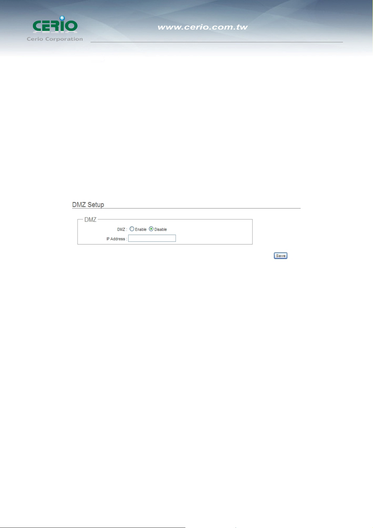
2.6.1 DMZ
DMZ is commonly work with the NAT functionality as an alternative of Virtual Server(Port Forwarding) while
wanting all ports of DMZ host visible to Internet users. Virtual Server rules have precedence over the DMZ rule. In
order to use a range of ports available to access to different internal hosts Virtual Server rules are needed.
Please click on Advance -> DMZ and follow the below setting.
DMZ : By default, it’s “Disable”. Check Enable radial button to enable DMZ.
IP Address : Enter IP address of DMZ host and only one DMZ host is supported.
Click Save button to save your changes. Click Reboot button to activate your changes.
2.6.2
“Virtual Server” can also referred to as “Port Forward” as well and used interchangeably. Resources in the
network can be exposed to the Internet users in a controlled manner including on-line gaming, video conferencing
Virtual Server (Port Forwarding)
or others via Virtual Server setup. Don’t repeat ports’ usage to avoid confusion.
Please click on Advance -> Virtual Server and follow the below setting.
66

User’s Manual
eXtreme High Power Wireless Router
Virtual Server : By Default, It’s “Disable”. Check Enable radial button to enable Virtual Server.
Description : Enter appropriate message for resource sharing via Virtual Server.
Private IP : Enter corresponding IP address of internal resource to share.
Protocol Type : Select appropriate sessions, TCP or UDP, from shared host via multiple private ports.
Private Port : A port or a range of ports may be specified as start:end; i.e. port 20:80
Public Port : A port or a range of ports may be specified as start:end; i.e. port 20:80
Notice: The Private Port and Public Port can be different. However, total number of ports need to
be the same.
Example : Public Port is 11 to 20 and the Private Port can be a 10 ports range.
Click “Add” button to add Virtual Server rule to List. Total of maximum 20 rules are allowed in this List. All rules can
be edited or removed from the List. Click Reboot button to activate your changes.
While creating multiple Virtual Server rules, the prior rules have higher priority. The Virtual server rules have
precedence over the DMZ one while both rules exist. Example 1 and 2 demonstrate proper usage of DMZ and
Virtual Server rules.
Example 1 : All connections should be redirected to 192.168.1.12 while DMZ is enabled. Since Virtual Server
rules have precedence over the DMZ rule all connections to TCP port 22 will be directed to TCP port 22 of
192.168.1.10 and remaining connections to port TCP 20~80 will be redirected to port TCP 20~80 of
67

User’s Manual
eXtreme High Power Wireless Router
192.168.1.11
DMZ Enabled : 192.168.1.12
Rule Protocol Private IP Private Port Public Port
1 TCP 192.168.1.10 22 22
2 TCP 192.168.1.11 20:80 20:80
Example 2 : All connections should be redirected to 192.168.1.12 while DMZ is enabled. Since Virtual Server
rules have precedence over the DMZ rule all other connections to TCP port 20~80 will be redirected to port
20~80 of 192.168.1.11. The rule 2 won’t take effect.
DMZ enabled : 192.168.1.12
Rule Protocol Private IP Private Port Public Port
1 TCP 192.168.1.11 20:80 20:80
2 TCP 192.168.1.10 22 22
68

User’s Manual
eXtreme High Power Wireless Router
2.7 System Status
This section breaks down into subsections of System Overview, Associated Clients Status, WDS Link Status,
Extra Information , QoS Plot and Eent Log.
2.7.1
Overview
Detailed information on System, WAN Information, LAN Information, Wireless Information and DHCP Server
Status can be reviewed via this page.
System : Display the information of the system.
Î System Name : The name of the system.
Î Operating Mode : The mode currently in service.
Î Location : The reminding note on the geographical location of the system.
Î Description : The reminding note of the system.
Î Firmware Version : The current firmware version installed.
Î Firmware Date : The build time of the firmware installed.
Î Device Time : The current time of the system.
Î System Up Time : The time period that system has been in service since last reboot.
WAN Information : Display the information of the WAN interface.
69

User’s Manual
eXtreme High Power Wireless Router
The WAN port specified Dynamic IP, the Release and Renew button will be show-up, click Release button to
release IP address of WAN port, Renew button to renew IP address through DHCP server.
The WAN port specified PPPoE , and the Connect and DisConnect button will be show up. Click “Connect”
button to assigned IP address from PPPoE server, “DisConnect” button to release IP address of WAN port.
Î Mode : Supports Static, Dynamic, PPPoE modes.
Î Reconnect Mode : The current reconnect mode of the PPPoE.
Î MAC Address : The MAC address of the WAN port.
Î IP Address : The IP address of the WAN port.
Î IP Netmask : The IP netmask of the WAN port.
Î IP Gateway : The gateway IP address of the WAN port.
Î Primary DNS : The primary DNS server in service.
70

eXtreme High Power Wireless Router
Î Secondary DNS : The secondary DNS server in service.
Î Receive bytes : The total received packets in bytes on the WAN port.
Î Receive packets : The total received packets of the WAN port.
Î Transmit bytes : The total transmitted packets in bytes of the WAN port.
Î Transmit packets : The total transmitted packets of the WAN port.
LAN Information : Display total received and transmitted statistics on the LAN interface.
User’s Manual
Î MAC Address : The MAC address of the LAN port.
Î IP Address : The IP address of the LAN port.
Î IP Netmask : The IP netmask of the LAN port.
Î Receive bytes : The total received packets in bytes on the LAN port.
Î Receive packets : The total received packets of the LAN port.
Î Transmit bytes : The total transmitted packets in bytes of the LAN port.
Î Transmit packets : The total transmitted packets of the LAN port.
Wireless Information : Display the detailed receive and transmit statistics of Wireless interface.
71

eXtreme High Power Wireless Router
Î MAC Address : The MAC address of the Wireless Port.
Î Receive bytes :The total received packets in bytes on the Wireless port.
Î Receive packets : The total received packets on the Wireless port.
Î Transmit bytes : The total transmitted packets in bytes on the Wireless port.
Î Transmit packets : The total transmitted packets on the Wireless port.
User’s Manual
DHCP Server Status : Users could retrieve DHCP server and DHCP clients’ IP/MAC address via this field.
Î IP Address : IP addresses to LAN devices by DHCP server.
Î MAC Address : MAC addresses of LAN devices.
Î Expired In : Shows how long the leased IP address will expire.
2.7.2
Associated Clients Status
It displays ESSID, on/off Status, Security Type, total number of wireless clients associated with all Virtual AP.
72

User’s Manual
eXtreme High Power Wireless Router
Wireless Information : Highlights key VAP information.
Î VAP : Available VAP from VAP0 to VAP7.
Î ESSID : Display name of ESSID for each VAP.
Î Status : On/Off
Î Security Type : Display chosen security type; WEP, WPA/WPA2-PSK, WPA/WPA2-Enterprise.
Î Clients : Display total number of wireless connections for each VAP.
VAP0-VAP7 Associated Client Status : Display all associated clients on each Virtual AP.
Î MAC Address : Display MAC address for VAP of associated clients.
Î RSSI : RSSI of from associated clients.
Î Last TX Time : Last inactive time period in seconds for a wireless connection.
Î Disconnect : Click “Delete” button to manually disconnect a wireless client in a Virtual AP.
73

User’s Manual
eXtreme High Power Wireless Router
2.7.3
Peers MAC Address, antenna 0/1 received signal strength, phy mode and channel bandwidth for each WDS are
available.
Show WDS Link Status
MAC Address : Display MAC address of WDS peer.
Signal Strength ANT0/ANT1 : Indicate the signal strength of the respective WDS links.
Phy Mode : Indicate the phy mode of the respective WDS linked.
BandWidth : Indicate the channel bandwidth of the respective WDS linked.
If display “no signal” Signal Strength ANT0/ANT1, you need check WDS configuration.
Things to verify are MAC Address, Channel and Security type. Also, adjust antenna
angle and Tx Power.
74

User’s Manual
eXtreme High Power Wireless Router
2.7.4
Users could pull out information such as Route table, ARP table, MAC table, Bridge table or STP available in the
drop-down list from system. The “Refresh” button is used to retrieve latest table information.
Extra Info
Netstat Information : Select “NetStatus Information” on the drop-down list, the connection track list
should show-up, the list can be updated using the Refresh button.
NetStatus will show all connection track on the system, the information include Protocol, Live Time, Status ,
Source/Destination IP address and Port.
Route table information : Select “Route table information” on the drop-down list to display route table.
DiToG DT-100G could be used as a L2 or L3 device. It doesn’t support dynamic routing protocols such as RIP or
OSPF. Static routes to specific hosts, networks or default gateway are set up automatically according to the IP
configuration of system's interfaces. When used as a L2 device, it could switch packets and, as L3 device, it’s
capable of being a gateway to route packets inward and outward.
ARP table Information : Select “ARP Table Information” on the drop-down list to display ARP table.
ARP associates each IP address to a unique hardware address (MAC) of a device. It is
important to have a unique IP address as final destination to switch packets to.
75

User’s Manual
eXtreme High Power Wireless Router
Bridge table information : Select “Bridge Table information” on the drop-down list to display bridge table.
Bridge table will show Bridge ID and STP's Status on the each Ethernet bridge and its attached interfaces, the
Bridge Port should be attached to some interfaces e.g. ra0 ~ra6 and wds0~wds3).
Bridge MAC information : Select “Bridge MACs Information” on the drop-down list to display MAC table.
This table displays local MAC addresses associated with wired or wireless interfaces, but also remember
non-local MAC addresses learned from wired or wireless interfaces.
Ageing timers will be reset when existing MAC addresses in table are learned again or added when new MAC
addresses are seen from wired or wireless interfaces as well. When time runs out for a particular entry, it will be
pruned from the table. In that situation, switching packet to that particular MAC address will be discontinued.
76

User’s Manual
eXtreme High Power Wireless Router
Bridge STP Information : Select “Bridge STP Information” on the drop-down list to display a list of bridge
STP information.
2.7.5
The QoS Plot show graphs which continuously represents the current data traffic on each QoS rule. The chart
scale and throughput dimension (bps, Kbps, Mbps) changes dynamically according to the mean throughput value.
The statistics is updated automatically every 5 seconds. The throughput statistics of QoS can be updated manually
using the Refresh button.
QoS Plot
77
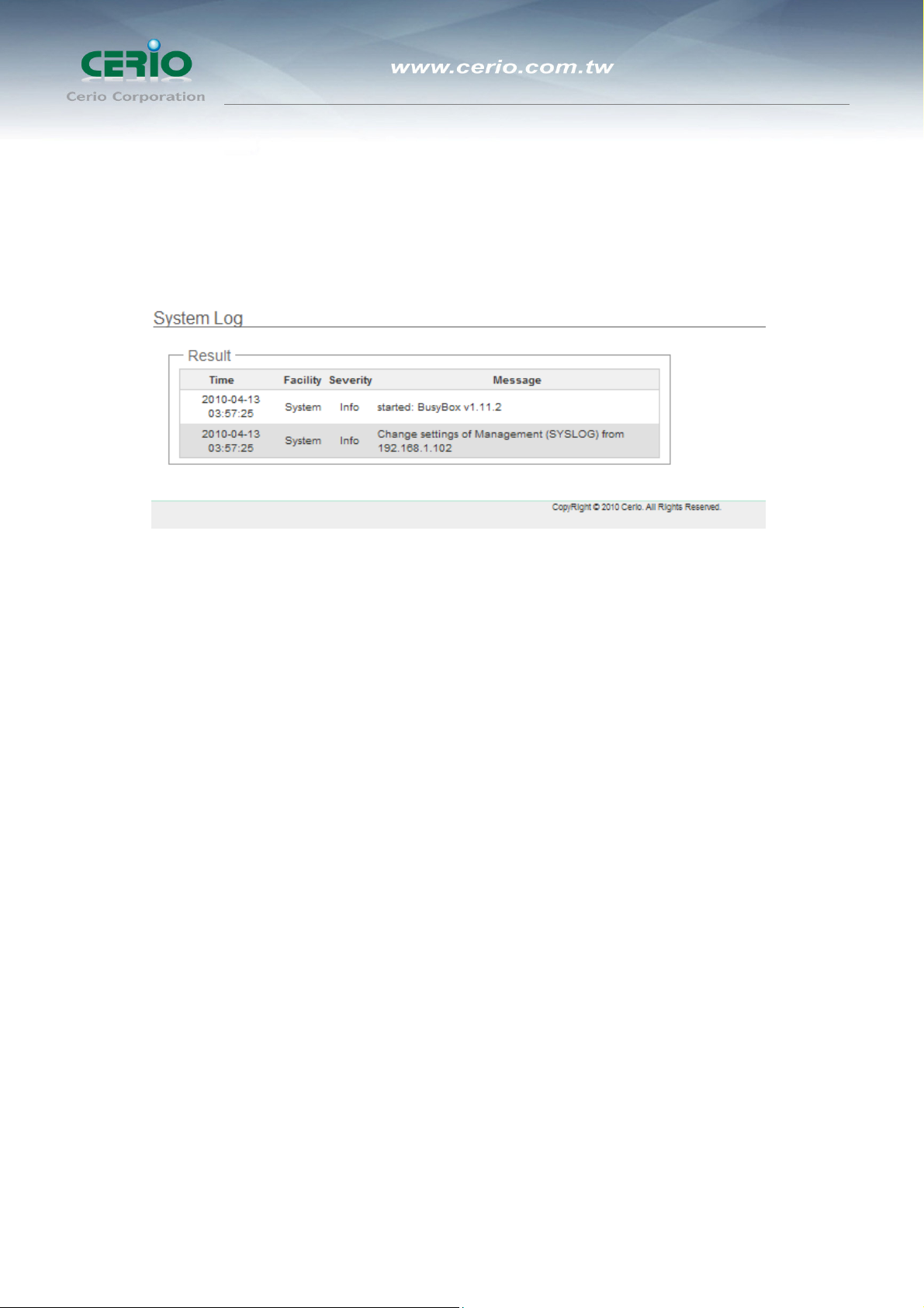
User’s Manual
eXtreme High Power Wireless Router
2.7.6
The Event log displays system events when system is up and running. Also, it becomes very useful as a
troubleshooting tool when issues are experienced in system.
Event Log
Time : The date and time when the event occurred.
Facility : It helps users to identify source of events such “System” or “User”
Severity : Severity level that a specific event is associated such as “info”, “error”, “warning”, etc.
Message : Description of the event.
Click Refresh button to renew the log, or click Clear button to clear all the record.
78

User’s Manual
eXtreme High Power Wireless Router
WISP + AP Mode Configuration
When WISP+AP mode is chosen, the system can be configured as a Customer
Premises Equipment(WISP). This section provides detailed explanation for users
to configure in the WISP+AP mode with help of illustrations. In the WISP+AP
mode, functions listed in the table below are also available from the Web-based
GUI interface.
79

User’s Manual
eXtreme High Power Wireless Router
3 WISP + AP Mode Configuration
WISP+AP Mode Functions
OPTION System Wireless Advance Utilities Status
Operating Mode General Setup DMZ Profiles Settings System Overview
WAN Advanced Setup IP Filter Firmware Upgrade Station Statistics
LAN Repeater AP Setup MAC Filter Network Utility Extra Info
Functions
DDNS Wireless Profile Virtual Server Reboot QoS Plot
Management Site Survey Parental Control Event Log
Time Server QoS
UPNP
SNMP
3.1 External Network Connection
3.1.1 Network Requirement
It can be used as an Wireless Internet Service Provider (WISP) to receive and repeat wireless signal over last
mile application, helping WISPs deliver wireless broadband Internet service to residents and business customers.
In the WISP+AP mode, DT-100G is a gateway enabled with NAT and DHCP Server functions. The wired and
wireless clients connected to DT-100G are in different subnet from those connected to Main Base Station, and, in
WISP+AP mode, it accepts wireless connections from wireless client devices.
80

User’s Manual
eXtreme High Power Wireless Router
WISP+AP mode network configuration
Notice: When the DT-100G configured as an Access Point and Client Station
simultaneously, the Wireless General and Advanced Setup also used simultaneously. But
the Security Type can be different. In the other word, the channel or other settings will be
the same between DT-100G to Main Base Station and wireless client to DT-100G , but
security type can be different.
81

eXtreme High Power Wireless Router
Configure WAN Setup
3.1.2
There are three connection types for the WAN port : Static IP, Dynamic IP, PPPoE,
Please click on System -> WAN and follow the below setting.
User’s Manual
Notice: In WISP mode, the WAN Port is the Wireless interface.
Mode : By default, it’s “Dynamic IP”. Check “Static IP”, “Dynamic IP”, “PPPoE” to set up system WAN IP.
Î Static IP : Users can manually setup the WAN IP address with a static IP provided by WISP.
9 IP Address : The IP address of the WAN port.
9 IP Netmask : The Subnet mask of the WAN port.
IP Gateway : The default gateway of the WAN port.
Î Dynamic IP : Please consult with WISP for correct wireless settings to associate with WISP AP before a
dynamic IP, along with related IP settings including DNS can be available from DHCP server. If IP
Address is not assigned, please double check with your wireless settings and ensure successful
association. Also, you may go to “WAN Information” in the Overview page to click Release button to
release IP address and click Renew button to renew IP address again.
82

eXtreme High Power Wireless Router
9 Hostname : The Hostname of the WAN port
Î PPPoE : To create wireless PPPoE WAN connection to a PPPoE server in network.
User’s Manual
9 User Name : Enter User Name for PPPoE connection
9 Password : Enter Password for PPPoE connection
9 Reconnect Mode :
• Always on – A connection to Internet is always maintained.
• On Demand – A connection to Internet is made as needed.
Notice: When Time Server is enabled at the “On Demand” mode, the “Reconnect Mode”
will turn out “Always on”.
• Manual – Click the “Connect” button on “WAN Information” in the Overview page to connect to
the Internet.
9 Idle Time : Time to last before disconnecting PPPoE session when it is idle. Enter preferred Idle
Time in minutes. Default is “0”, indicates disabled. When Idle time is disabled, the “Reconnect
Mode” will turn out “Always on”
9 MTU : By default, it’s 1492 bytes. MTU stands for Maximum Transmission Unit. Consult with WISP
for a correct MTU setting.
Click Save button to save your changes. Click Reboot button to activate your changes
83

eXtreme High Power Wireless Router
Configure DDNS Setup
3.1.3
Dynamic DNS allows you to map domain name to dynamic IP address.
Please click on System -> DDNS Setup and follow the below setting.
User’s Manual
Enabled: By default, it’s “Disable”. The mapping domain name won’t change when dynamic IP changes. The
beauty of it is no need to remember the dynamic WAP IP while accessing to it.
Service Provider: Select the preferred Service Provider from the drop-down list including dyndns, dhs, ods
and tzo
Hostname: Host Name that you register to Dynamic-DNS service and export.
User Name & Password: User Name and Password are used to login DDNS service.
Click Save button to save your changes. Click Reboot button to activate your changes
84

eXtreme High Power Wireless Router
Configure LAN Setup
3.1.4
Here are the instructions for how to setup the local IP Address and IP Netmask.
Please click on System -> LAN and follow the below setting.
User’s Manual
LAN IP : The administrator can manually setup the LAN IP address.
Î IP Address : The IP address of the LAN port; default IP address is 192.168.1.254
Î IP Netmask : The Subnet mask of the LAN port; default Netmask is 255.255.255.0
DHCP Setup : Devices connected to the system can obtain an IP address automatically when this service is
enabled.
Î DHCP : Check Enable button to activate this function or Disable to deactivate this service.
Î Start IP / End IP: Specify the range of IP addresses to be used by the DHCP server when assigning IP
85

User’s Manual
eXtreme High Power Wireless Router
address to clients. The default range IP address is 192.168.1.2 to 192.168.2.253, the netmask is
255.255.255.0
Î DNS1 IP : Enter IP address of the first DNS server; this field is required.
Î DNS2 IP : Enter IP address of the second DNS server; this is optional.
Î WINS IP : Enter IP address of the Windows Internet Name Service (WINS) server; this is optional.
Î Domain : Enter the domain name for this network.
Lease Time : The IP addresses given out by the DHCP server will only be valid for the duration
specified by the lease time. Increasing the time ensure client operation without interruptions, but could
introduce potential conflicts. Lowering the lease time will avoid potential address conflicts, but might
cause more interruptions to the client while it will acquire new IP addresses from the DHCP server.
Default is 86400 seconds
802.1d Spanning Tree
The spanning tree network protocol provides a loop free topology for a bridged LAN between
LAN interface and 8 WDS interfaces from wds0 to wds7. The Spanning Tree Protocol, which is
also referred to as STP, is defined in the IEEE Standard 802.1d.
Click Save button to save your changes. Click Reboot button to activate your changes
86

User’s Manual
eXtreme High Power Wireless Router
3.2 Access Point Association
3.2.1 Configure Wireless General Setting
The administrator can change the data transmission, channel and output power settings for the system. Please
click on Wireless -> General Setup and follow the below setting.
9 ESSID: you can specify the ESSID name you want connect to here.
9 Band Mode : Select an appropriate wireless band; bands available are 802.11b, 802.11g or
802.11b+802.11g mixed mode.
9 Transmit Rate Control : Select the desired rate from the drop-down list; the options are auto or
ranging from 6 to 54Mbps.
9 Country : Select the desired country code from the drop-down list; the options are US, ETSI, JP.
9 Channel : The channel range will be changed by selecting different country code. Below depicts the
channel range for different Country.
Country Channel
US
ETSI
JP
9 Tx Power : You can adjust the output power of the system to get the appropriate coverage for your
wireless network. Specify digit numbers between 1 to 100 (the unit is %) for your environment. If
Auto, 1~11
Auto, 1~13
Auto, 1~13
you are not sure which setting to choose, then keep the default setting, 100%.
87

User’s Manual
eXtreme High Power Wireless Router
9 Security Type: Select the desired security type from the drop-down list; the options are WEP,
WPA-PSK, WPA2-PSK.
13. Disable: Data are unencrypted during transmission when this option is selected.
14. WEP
WEP, Wired Equivalent Privacy, is a data encryption mechanism based on a 64-bit, 128-bit or
152-bit shared key. Select WEP as the security type from the drop down list as desired.
z Key Length: The key size of WEP encryption can be 64bit, 128bit or 152bit.
z WEP auth method: You can select the appropriate value: Open system (If enabling this mode,
there is no need authentication to access AP or Wireless NIC) or Shared (Only those who are
sharing the same key with the AP can connect with it).
z Key Index: You can select the Key which you want to use. Other wireless station must have the
same key value to connect with DT-100G, 4 different WEP keys can be configured at the same
time, but only one is used. Effective key is set with a choice of WEP Key 1, 2, 3 or 4.
z WEP Key #: You can chose either HEX or ASCII for your WEP key value, for 64bit encryption
strength can use 10 digits for HEX (0~9, a~f and A-F) or 5 digits for ASCII (0~9, a~z and A~Z), for
128bit encryption strength can use 26 digits for HEX (0~9, a~f and A-F) or 13 digits for ASCII (0~9,
a~z and A~Z), for 152bit encryption strength can use 32 digits for HEX (0~9, a~f and A-F) or 16
digits for ASCII (0~9, a~z and A~Z)
88

User’s Manual
eXtreme High Power Wireless Router
15. WPA-PSK (or WPA2-PSK): WPA-PSK is short for W-Fi Protected Access-Pre-Shared Key.
WPA-SPK uses the same encryption way with WPA, and the only difference between them is that
WPA-PSK recreates a simple shared key, instead of using the user’s certification.
z Cipher Suite:
You can chose use AES or TKIP with your WPA / WPA2 encryption method,
AES is short for “Advanced Encryption Standard”, The AES cipher is specified as a number of
repetitions of transformation rounds that convert the input plaintext into the final output of
ciphertext. Each round consists of several processing steps, including one that depends on the
encryption key. A set of reverse rounds are applied to transform ciphertext back into the original
plaintext using the same encryption key.
TKIP is short for “Temporal Key Integrity Protocol”, TKIP scrambles the keys using a hashing
algorithm and, by adding an integrity-checking feature, ensures that the keys haven’t been
tampered with.
z Key Type:
Check on the respected button to enable either ASCII or HEX format for the Pre-shared Key.
z Pre-Shared Key:
Enter the information for pre-shared key; the format of the information shall according to the key
type selected. Pre-shared key can be either entered as a 256-bit secret in 64 HEX digits format,
or 8 to 63 ASCII characters.
Click Save button to save your changes. Click Reboot button to activate your changes.
89

User’s Manual
eXtreme High Power Wireless Router
Wireless Advanced Setup
3.2.2
To achieve optimal wireless performance, it is necessary to tweak advance setting per requirements properly, not
necessary higher the better or lower.
The administrator can change the RTS threshold and fragmentation threshold settings for the system. Please click
on Wireless -> Advanced Setup and follow the below setting.
¾ Slot Time: Enter the desired slot time for the AP.
¾ ACK Timeout: The time interval for waiting the “ACK nowledgment frame”. If the ACK is not
received within that timeout period then the packet will be re-transmitted. Higher ACK Timeout will
decrease the packet lost, but the throughput will be growing worse.
¾ CTS Timeout: Enter the desired CTS timeout for the AP.
Notice: Slot Time and ACK/CTS Timeout settings for long distance links. It is important to
change the value to find the optimal setting. A value too low will give very low throughput,
A high value may slowdown the link.
¾ RSSI Threshold: RSSI Threshold can be used to control the level of noise received by the device.
90

User’s Manual
eXtreme High Power Wireless Router
¾ Beacon Interval: Enter a value between 10 and 5000 msec. The default value is 100 milliseconds.
The entered time means how often the beacon signal transmission between the access point and
the wireless network.
¾ DTIM Interval: Input the DTIM Interval that is generated within the periodic beacon at a specified
frequency. Higher DTIM will let the wireless client save energy more, but the throughput will be
growing worse.
¾ Fragment Threshold: The value specifies the maximum size of packet allowed before data is
fragmented into multiple packets. Please use this value to tune the wireless connection if lots of
retransmission happens. Enter a value ranging from 256 to 2346.
¾ RTS Threshold: Tuning the Request to Send, RTS threshold will help the system control its access
to medium and alleviate the hidden node problem. Enter a value ranging from 1 to 2346.
¾ Short Preamble: The short preamble provides 56-bit Synchronization field to improve WLAN
transmission efficiency. Check Enable button for using Short Preamble, and Disable for using the
Long Preamble, 128-bit Synchronization field, option.
¾ Tx Burst: Click Enable button to activated Tx Burst, and Disable to unactivated Tx Burst.
¾ 802.11g Protection Mode: Click Enable button to activated 802.11g Protection Mode, and Disable
to unactivated 802.11g Protection Mode.
Change these settings as described here and click Save button to save your changes. Click
Reboot button to activate your changes. The items in this page is for Router AP's RF general
settings and will be applied to all VAPs.
91

eXtreme High Power Wireless Router
Site Survey
3.2.3
Use this tool to scan and locate WISP Access Points and select one to associate with.
Please click on Wireless -> Site Survey. Below depicts an example for site survey.
9 ESSID : Available Extend Service Set ID of surrounding Access Points.
User’s Manual
9 MAC Address : MAC addresses of surrounding Access Points.
9 Channel : Channel numbers used by all found Access Points.
9 Signal Level: Received signal strength of all found Access Points.
9 Security Type : Security type by all found Access Points.
9 Setup : Click “Select” to configure settings and associate with chosen AP.
Notice: While clicking “Select” button in the Site Survey Table, the “ESSID” and “Security
Type” will apply in the Wireless General Setup. However, more settings are needed
including Security Key.
While clicking “Select” button in the Site Survey Table, Please check to Wireless -> General
Setup the apply from Site Survey table connect information . Please by your Security status to
including Security Key.
92

User’s Manual
eXtreme High Power Wireless Router
Change these settings as described here and click Save button to save your changes. Click Reboot button to
activate your changes
93

User’s Manual
eXtreme High Power Wireless Router
3.3 Wireless LAN Network Creation
The network manager can configure related wireless settings, Repeater AP Setup, Security Settings, and MAC
Filter Settings.
Repeater AP Setup
3.3.1
Administrators can configure ESSID, SSID broadcasting, Maximum number of client associations, security type
settings and MAC Filter settings.
ESSID : Extended Service Set ID, When clients are browsing for available wireless networks, this is the
SSID that will appear in the list. ESSID will determine the service type available to AP's clients associated with
the specified AP.
Enable Repeater AP : By default, it’s “Enable” for repeater AP. Select “Enable” to activate Repeater AP or
click “Disable” to deactivate this function
Hidden SSID : By default, it’s “Disable”.
Enable this option to stop the SSID broadcast in your network. When disabled, people could easily obtain the
SSID information with the site survey software and get access to the network if security is not turned on. When
enabled, network security is enhanced. It’s suggested to enable it after AP security settings are archived and
setting of AP's clients could make to associate to it.
Client Isolation : By default, it’s “Disable”.
94

User’s Manual
eXtreme High Power Wireless Router
Select “Enable”, all clients will be isolated from each other, which means they can’t reach each other.
Maximum Clients : The default value is 32. You can enter the number of wireless clients that can associate to
a particular SSID. When the number of client is set to 5, only 5 clients at most are allowed to connect to this
Repeater AP.
Security Type : Select the desired security type from the drop-down list; the options are Disable, WEP,
WPA-PSK, WPA2-PSK, WPA-Enterprise, WPA2-Enterprise and WEP 802.1X.
3.3.1.1 Disable : Data are unencrypted during transmission when this option is selected.
3.3.1.2 WEP : Wired Equivalent Privacy(WEP) is a data encryption mechanism based on a
64-bit or 128-bit and 152 –bit shared key.
9 Authentication Method : Enable the desire option among OPEN, SHARED or WEPAUTO.
9 Key Index : key index is used to designate the WEP key during data transmission. 4 different WEP
keys can be entered at the same time, but only one is chosen.
9 WEP Key # : Enter HEX or ASCII format WEP key value; the system supports up to 4 sets of WEP
keys.
Key Length Hex ASCII
64-bit 10 characters 5 characters
128-bit 26 characters 13 characters
152-bit 32 characters 16 characters
3.3.1.3 WPA-PSK (or WPA2-PSK) : WPA (or WPA2) Algorithms, allows the system accessing
95

User’s Manual
eXtreme High Power Wireless Router
the network by using the WPA-PSK protected access.
9 Cipher Suite : By default, it is TKIP. Select either AES or TKIP cipher suites
9 Pre-shared Key : Enter the pre-shared key; the format shall go with the selected key type.
Notice: Pre-shared key can be entered with either a 256-bit secret in 64 HEX digits
format, or 8 to 63 ASCII characters.
9 Group Key Update Period : By default, it is 3600 seconds. This time interval for rekeying GTK,
broadcast/multicast encryption keys, in seconds. Entering the time-length is required.
3.3.1.4 WPA-Enterprise (or WPA2-Enterprise) General Setting
The RADIUS authentication and encryption will be both enabled if this selected.
96

9 WPA General Settings :
z Cipher Suite:
You can chose use AES or TKIP with your WPA / WPA2 encryption method,
AES is short for “Advanced Encryption Standard”, The AES cipher is specified as a number of
repetitions of transformation rounds that convert the input plaintext into the final output of ciphertext.
Each round consists of several processing steps, including one that depends on the encryption key. A set
of reverse rounds are applied to transform ciphertext back into the original plaintext using the same
encryption key.
TKIP is short for “Temporal Key Integrity Protocol”, TKIP scrambles the keys using a hashing algorithm
and, by adding an integrity-checking feature, ensures that the keys haven’t been tampered with.
z Group Key Update Period:
User’s Manual
eXtreme High Power Wireless Router
This time interval for re-keying GTK (broadcast/multicast encryption keys) in seconds. Enter the
time-length required; the default time is 600 seconds.
z Master Key Update Period:
This time interval for re-keying GMK (master key used internally to generate GTKs) in seconds. Enter the
time-length required; the default time is 83400 seconds.
EAP Reauth Period:
This time interval for re- authentication in seconds. Enter the time-length required; the default time is
3600 seconds; 0 = disable re-authentication.
1. Authentication RADIUS Server Settings
z Authentication Server: Enter the IP address of the Authentication RADIUS server.
z Port: The port number used by Authentication RADIUS server. Use the default 1812 or enter port number
specified.
z Shared secret: The secret key for system to communicate with Authentication RADIUS server. Support 1
to 64 characters.
97

User’s Manual
eXtreme High Power Wireless Router
z Accounting Server: Check on the respected button to enable either Enable or Disable accounting
RADIUS server.
2. Accounting Server Settings
z Accounting Server: Enter the IP address of the Accounting RADIUS server.
z Port: The port number used by Accounting RADIUS server. Use the default 1813 or enter port number
specified.
z Shared Secret: The secret key for system to communicate with Accounting RADIUS server. Support 1 to
64 characters.
3. Secondary Authentication RADIUS Server
z Authentication Server: Enter the IP address of the Authentication RADIUS server.
z Port: The port number used by Authentication RADIUS server. Use the default 1812 or enter port number
specified.
z Shared secret: The secret key for system to communicate with Authentication RADIUS server. Support 1
to 64 characters.
z Accounting Server: Check on the respected button to enable either Enable or Disable accounting
RADIUS server.
4. (Secondary) Accounting Server Settings
z Accounting Server: Enter the IP address of the Accounting RADIUS server.
z Port: The port number used by Accounting RADIUS server. Use the default 1813 or enter port number
specified.
98

User’s Manual
eXtreme High Power Wireless Router
z Shared Secret: The secret key for system to communicate with Accounting RADIUS server. Support 1 to
64 characters.
z WEP 802.1x
When WEP 802.1x Authentication is enabled, please refer to the following Dynamic WEP and RADIUS
settings to complete the configuration.
5. Dynamic WEP Settings
z WEP Key length: Check on the respected button to enable either 64bits or 128bits key length. The system
will automatically generate WEP keys for encryption.
z WEP Key Update Period: The time interval WEP will then be updated; the unit is in seconds; default is
300 seconds; 0 = do not rekey.
z EAP Reauth Period: EAP re-authentication period in seconds; default is 3600; 0 = disable
re-authentication.
99

User’s Manual
eXtreme High Power Wireless Router
6. Authentication RADIUS Server Settings
z Authentication Server: Enter the IP address of the Authentication RADIUS server.
z Port: The port number used by Authentication RADIUS server. Use the default 1812 or enter port number
specified.
z Shared secret: The secret key for system to communicate with Authentication RADIUS server. Support 1
to 64 characters.
z Accounting Server: Check on the respected button to enable either Enable or Disable accounting
RADIUS server.
7. Accounting Server Settings
z Accounting Server: Enter the IP address of the Accounting RADIUS server.
z Port: The port number used by Accounting RADIUS server. Use the default 1813 or enter port number
specified.
z Shared Secret: The secret key for system to communicate with Accounting RADIUS server. Support 1 to
64 characters.
100
 Loading...