

Page 1
CERIO Corporation
PoE CS-2000 Series 2 Combo Gigabit + 24 port 10/100Mbps
CS-2224-24P
Web Managed PoE+ Switch
User’s Manual
Page 2

FCC Warning
This device has been tested and found to comply with limits for a Class A digital device, pursuant
to Part 2 and 15 of the FCC Rules. These limits are designed to provide reasonable protection
against harmful interference when the equipment is operated in a commercial environment.
This equipment generates, uses and can radiates radio frequency energy and, if not installed
and used in accordance with the user’s manual, may cause interference in which case user will
be required to correct the interference at his own expense.
CE Mark Warning
This is a Class A product. In a domestic environment, this product may cause radio interference
in which case the user many be required to take adequate measures.
Page 3

1. Introduction ......................................................................................................................................... 5
1.1 Feature ........................................................................................................................................ 5
1.2 Package Contents .................................................................................................................... 6
1.3 Front Panel ................................................................................................................................. 7
1.4 Rear Panel Layout .................................................................................................................... 8
1.5 Connections ............................................................................................................................... 8
2. Software Configuration .................................................................................................................... 9
Example of Segment: (Windows 7) ................................................................................................ 9
2.1 System login username and password information ..................................................... 13
3. Management ...................................................................................................................................... 14
3.1 Authentication Configuration.............................................................................................. 14
3.2 System IP Configuration ...................................................................................................... 15
3.3 System Status ......................................................................................................................... 16
3.5 Firmware Update .................................................................................................................... 19
3.6 Reboot Device ......................................................................................................................... 20
4. Port Management ............................................................................................................................. 21
4.2 Port Mirroring .......................................................................................................................... 22
4.3 Bandwidth Control ................................................................................................................. 23
4.4 Broadcast Storm Control ..................................................................................................... 24
4.5 PoE ............................................................................................................................................. 25
5. VLAN Setting ..................................................................................................................................... 26
5.1 VLAN Mode .............................................................................................................................. 26
5.2 VLAN Member Setting (Tag Based) ................................................................................... 28
5.3 Multi to 1 Setting ..................................................................................................................... 30
6. Per Port Counter .............................................................................................................................. 31
7. QoS Setting ....................................................................................................................................... 32
7.1 Priority Mode ........................................................................................................................... 32
7.2 Class of Service ...................................................................................................................... 34
7.3 Class of Service Configuration ........................................................................................... 35
8. Security .............................................................................................................................................. 36
8.1 MAC address Binding ........................................................................................................... 36
8.2 Service Protocol Filter .......................................................................................................... 38
9. Spanning Tree ................................................................................................................................... 40
9.1 STP Bridge Settings .............................................................................................................. 40
9.2 STP Port Setting ..................................................................................................................... 41
10. Trunk ................................................................................................................................................... 42
Page 4

11. DHCP Relay Agent ........................................................................................................................... 45
11.1 DHCP Relay Agent ................................................................................................................. 45
11.2 Relay Server ............................................................................................................................. 46
11.3 VLAN MAP Relay Agent ........................................................................................................ 47
12. Backup/Recovery ............................................................................................................................. 48
13. Other Setting ..................................................................................................................................... 49
14. Logout ................................................................................................................................................. 51
Specifications ............................................................................................................................................. 52
Page 5

1. Introduction
The CERIO CS-2224-24P Web Managed is a powerful high-performance 24 port POE Fast
Ethernet switch and support 2 combo Gigabit UTP/SFP uplink ports. The models compliant to
POE IEEE 802.3af, it defines new green power saving idea on PSE Port. That can solve the
limitation of the power outlet location and offer the system relocation easily. CS-2224-24P
layer 2 Web Management switch support Remote on/off control by PoE. And support
Port-base VLAN and IEEE802.1q tag-base VLAN based on ports & VIDs, and bandwidth control
and security support MAC /TCP/UDP Filter etc.
The CS-2224-24P case is designed for small office and can be upgrade to 1U” chassis .It is
ideal for micro-segmenting large networks into smaller, connected subnets for improved
performance, enabling the bandwidth demanding multimedia and imaging applications. You
could easily connect a POE Wireless AP or a VoIP phone or IPCAM to this switch without
looking outlets for them. Over current protection and circuit shorting protection are also
supported to ensure the safety. That high power device provides easy installation and the
limitation of the power outlet location and offers the system relocation easily.
1.1 Feature
Complying with IEEE 802.3 10Base-T, IEEE 802.3u 100Base-TX, IEEE 802.3ab
1000Base-T, IEEE 802.3z 1000Base-SX/LX IEEE-802.3af PoE,IEEE802.3at POE+
24port 10/100Mbps TX Auto-Negotiation Ethernet Switch , Have 24 Port PSE/ PoE
function, compliant with IEEE-802.3af class3 /class2/class1 and IEEE802.3at
Support 2 combo Gigabit UTP/SFP uplink ports and IEEE 802.3ab 1000Base-T, IEEE
802.3z 1000Base-SX/LX
Supporting PoE+ Green power Management by Link up mode to auto detect the level
class of Power device, budgets power output for each port. and Power down mode to auto
detect no link/ standby of Power device
Supporting the power up to 30Watt/15.4Watt/7.5Watt/4Watt for each PSE/PoE port
Full/Half-Duplex capability on each TX port , Auto-learning networking configurations
Supports Store & Forward architecture and performs forwarding and filtering
Supporting the flow control: back pressure for Half-duplex and IEEE 802.3x for Full-duplex
mode
Broadcast storm control and supporting store & forward operation
Non-blocking & Non-head-of-line blocking full-wire speed forwarding
Supports TP interface Auto MDIX function for auto TX/RX swap
Page 6

CS-2224-24P Main Unit
x1 CD Manual
x1 Power Code
x1
19” Mount Brackets
x1
Warranty Card
x1
Automatic Source MAC Address Learning and Aging
Supports up to 4K MAC addresses
Up to 3.5M bits buffer
VLAN and IEEE802.1Q tag-base VLAN based on ports & VIDs; add/remove/modify tag
IEEE802.3ad Link Aggregation Port trunking(up to 3 groups and Max. 4 ports in each
group)
Provide IGMP v1/v2 snooping function
Support QOS Class Quality of service ( COS ), port- based, 802.1q priority tag based, IP
TOS based, TCP/UDP port bases, 4 queues for per port WRR/FIFS algorithm
Support bandwidth control and Broadcast Storm Control
Supports port mirroring and Spanning Tree functions.
Per port MAC address base filtering and TCP/UDP filtering
Supports file backup and recovery
SNMP v1 , SNMP v2C support and Web-based management interface
1.2 Package Contents
Before you start to install this switch, please verify your package that contains the following
items:
Page 7
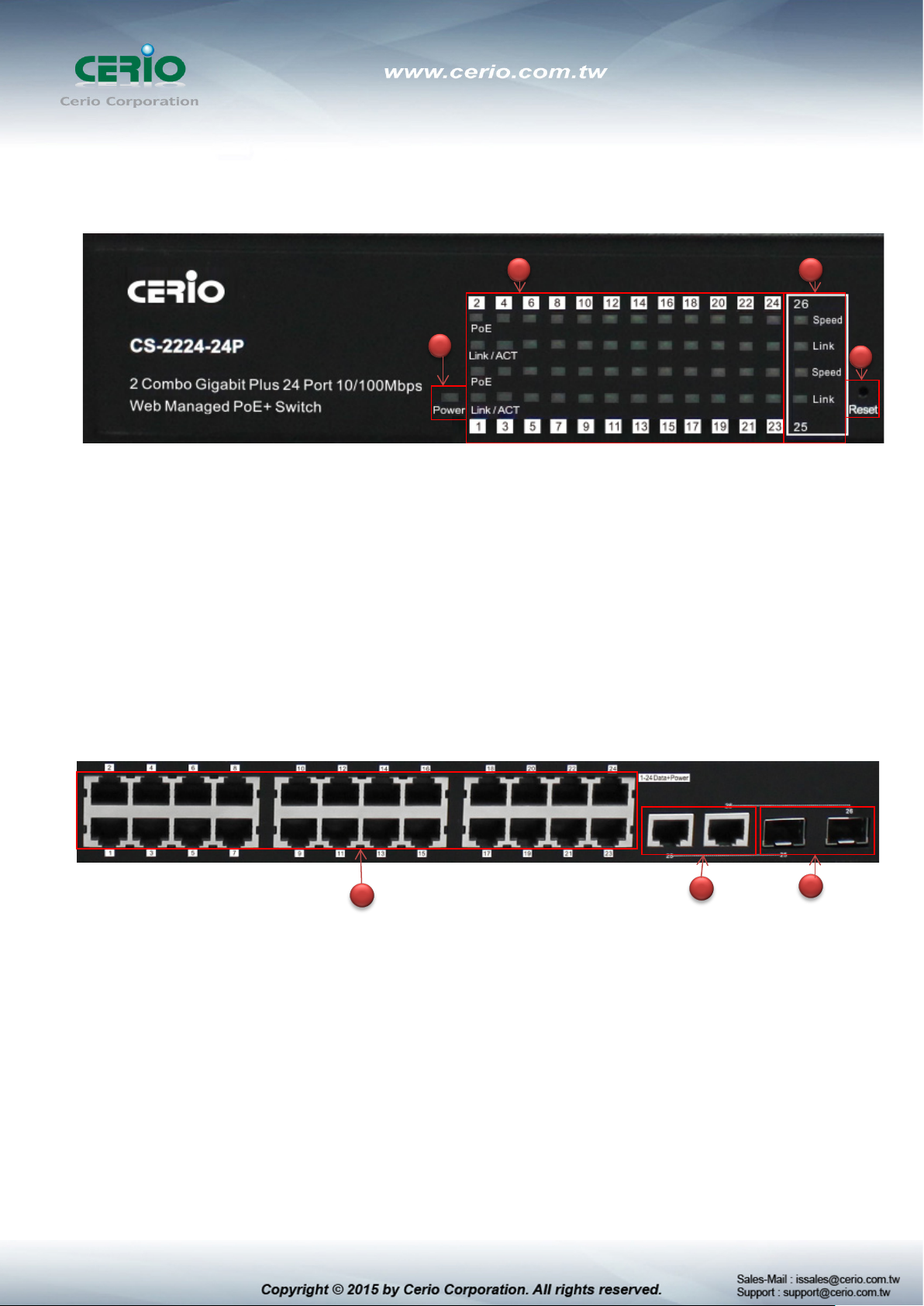
1.3 Front Panel
LED Indicators of 24 Port 10/100Mps + 2 giga Switch
2 3
1
1) Power LED the color is Yellow
2) 24 Port PoE and Ethernet Link/ACT LED, Port is linked to Power Device the PoE Lights up
LED, Port is data linked the Link/ACT Lights up LED, The Link / ACT Flashing represent
10/100Mbps for data activating
3) 2 Port Giga linked LED, Port is linked to Giga Device the Speed Lights up LED. Port is data
linked the Link/ACT Lights up LED, The Link / ACT Flashing represent 10/100/1000Mbps
for data activating
4) Hardware Reset to default button, hold down for about 10 seconds, until LED flashes
rapidly, Release will return to the default
24 port + 2 Giga port
4
1) 24 10/100Mbps PoE Ethernet Port
2) 2 Giga Ethernet Port
3) 2 Fiber Port
1
2
3
Page 8

xDSL
RJ-45 Data and PoE Out
1.4 Rear Panel Layout
1
1) AC input (100-240V/AC, 50-60Hz) UL Safety)
2) Two radiator fan
2
1.5 Connections
Switch/Hub to this 8 Port with 8 Port Fast Ethernet PoE Switch
This switch provides automatic crossover detection functionality for any port. It is simple and
friendly to up-link to another switch without crossover cable.
IP Camera
with PoE
Giga to Giga uplink
Other devices Un-PoE
AP With PoE
Other devices With PoE
Page 9
PC/Other devices to this 24 Port Fast Ethernet PoE Switch
Via a twisted pair cable straight through, this switch can be connected to PCs, servers and
other network devices.
Power Device to this 24 Port with 24 Port Fast Ethernet PoE Switch and getting 48V
power source through Cat. 5/6 cables
Using Cat. 5/6 twisted-pair cable to connect Power Device to the port 1~24 of this switch, and
then this switch will supply 48V power to Power Device over Cat. 5/6 twisted-pair cable. Please
be noted Power Device should also comply with IEEE 802.3af/ IEEE802.3at. and the PoE
Power Max. 30Watt each PSE/PoE port
2. Software Configuration
CS-2224-24P supports web-based configuration. Upon the completion of hardware installation,
CS-2224-24P can be configured through a PC/NB by using its web browser such as Internet
Explorer 6.0 or later.
Set the IP segment of the administrator's computer to be in the same range as CS-2224-24P for
accessing the system. Do not duplicate the IP Address used here with IP Address of CS-2224-24P
or any other device within the network. Please refer to the following steps
Example of Segment: (Windows 7)
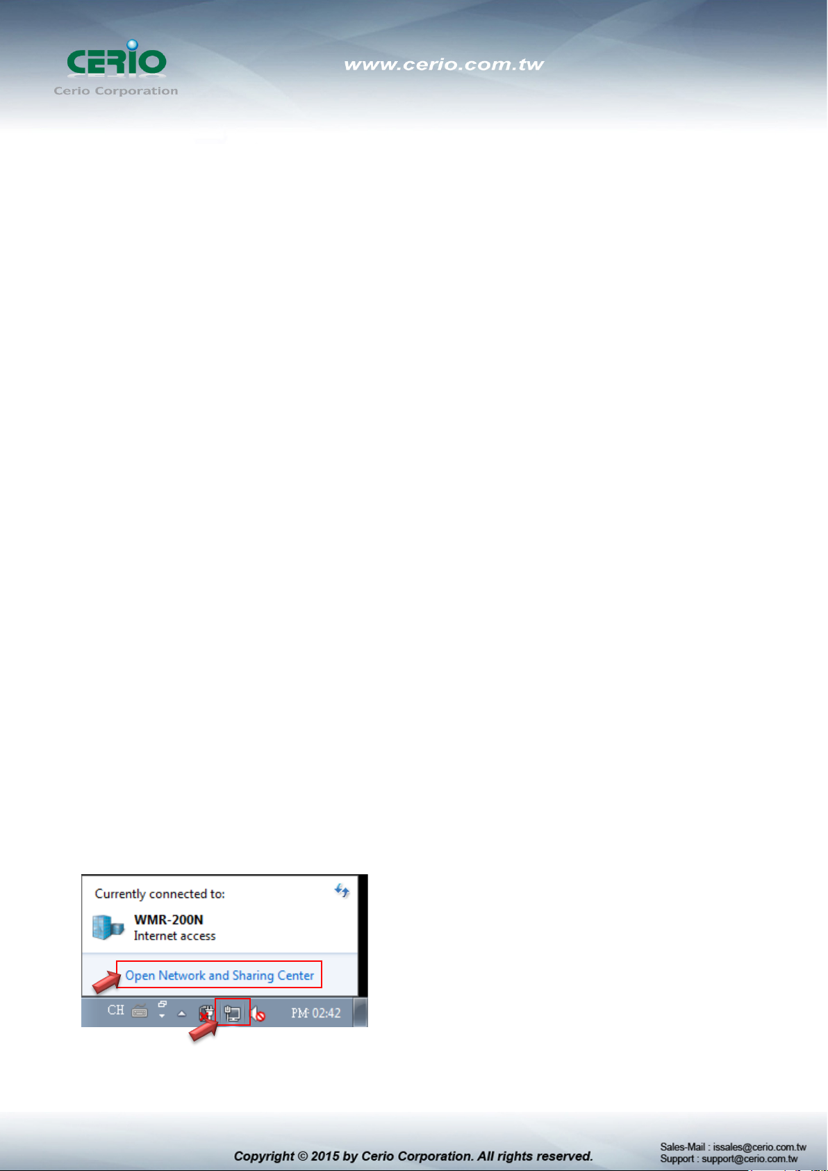
Step 1 :
Please click on the computer icon in the bottom right window, and click “Open Network and
Sharing Center”
Page 10
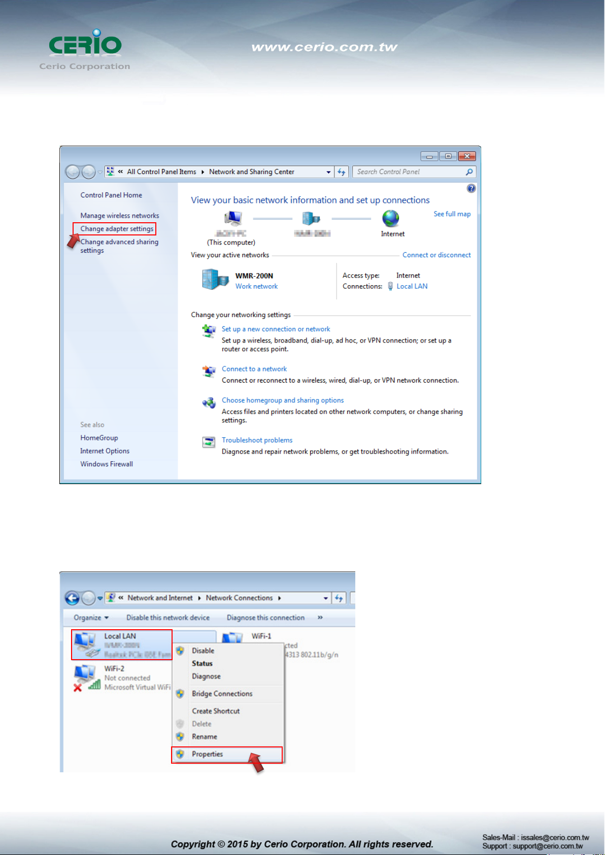
Step 2 :
In the Network and Sharing Center page, Please click on the left side of “Change adapter
setting” button
Step 3 :
In “Change adapter setting” Page. Please find Local LAN and Click the right button on the
mouse and Click “Properties”
Page 11

Double click
Step 4 :
In “Properties” page, please Click “Properties” button to TCP/IP setting
Step 5 :
In Properties page to setting IP address, please find “Internet Protocol Version 4
(TCP/IPv4)” and double click or click “Install” button.
Page 12
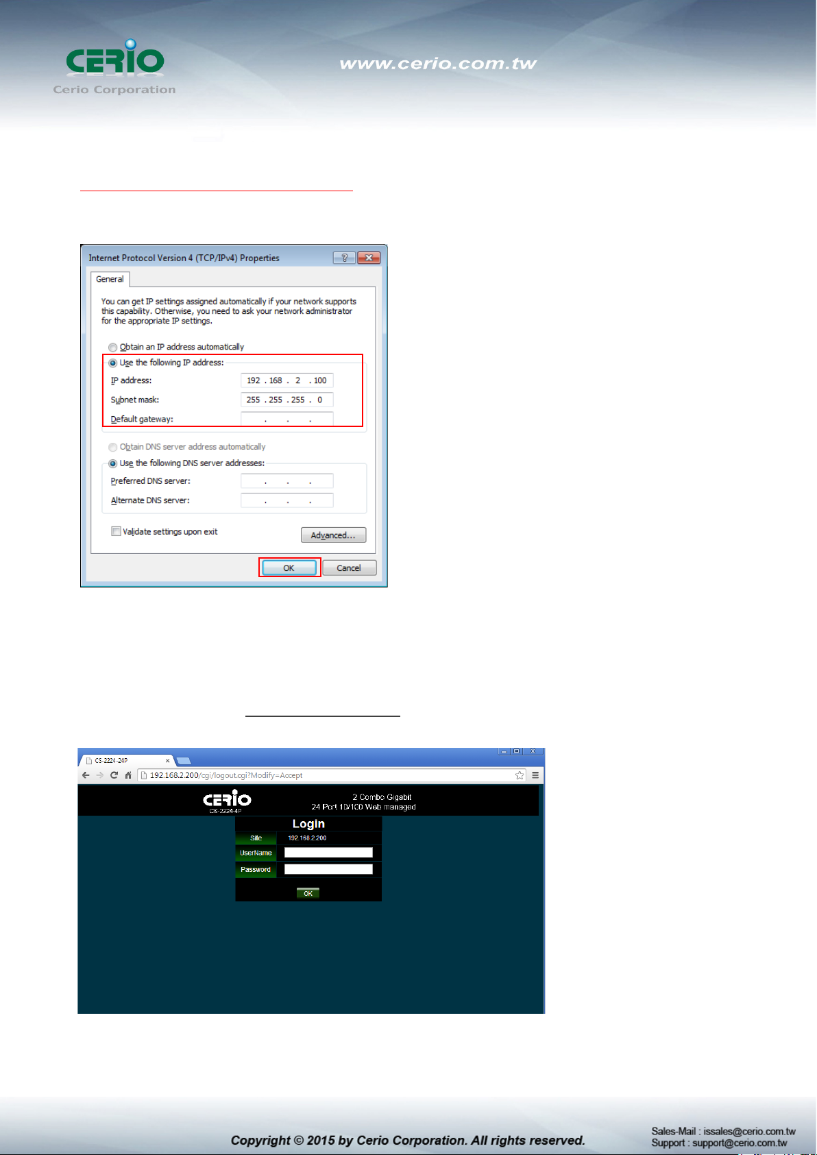
Step 6 :
Select “Use the following IP address”, and fix in IP Address : 192.168.2.X
ex. The X is any number by 1 to 253
Subnet mask : 255.255.255.0
And Click "OK" to complete the fixed computer IP setting
Step 7 :
Open Web Browser
Without a valid certificate, users may encounter the following problem in IE7 when they try to
access system's WMI (https://192.168.2.200). There will be a “Certificate Error”, because the
browser treats system as an illegal website.
System login Overview page will appear after successful login.
Page 13
Management Account
Username
Password
default
2.1 System login username and password information
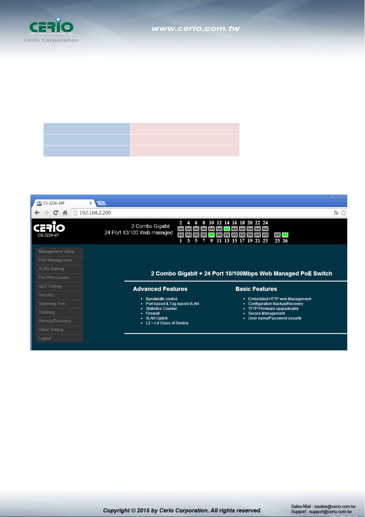
The CS-2224-24P web switch default IP is 192.168.2.200
Into the management page as follows, please enter Username and password
Default IP Address: 192.168.2.200
Default Username and Password
Root Account
root
After the authentication procedure, the home page shows up. Select one of the configurations by
clicking the icon.
Page 14
3. Management
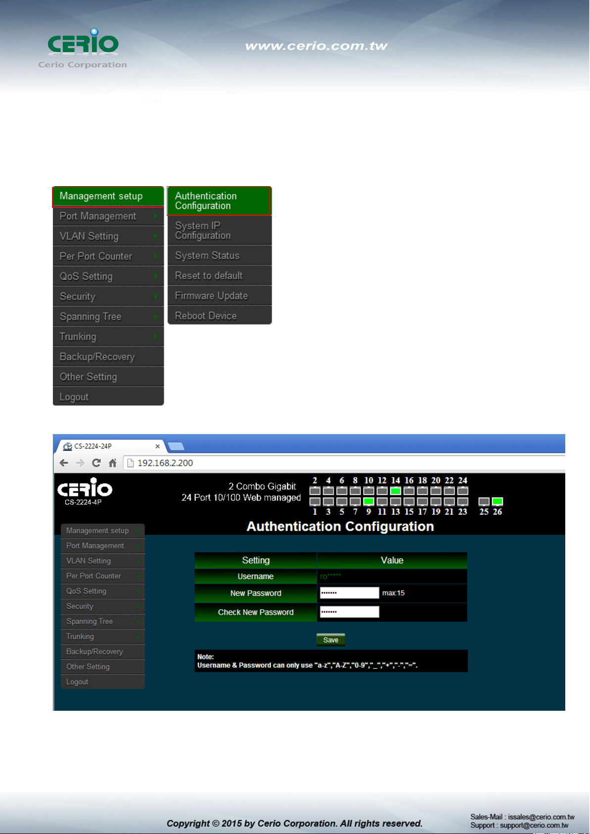
3.1 Authentication Configuration
This page allows the user to change the user name and the password.
Please click Management setup Authentication Configuration
Login as administrator user is root and the password is allowed to change its own password.
Username : Management account is “root”
New Password : Enter a new password if desired ( max. 15)
Page 15
Check New Password : Enter the same new password again to check.
Click “Save” button to save your changes. Click Reboot button to activate your changes
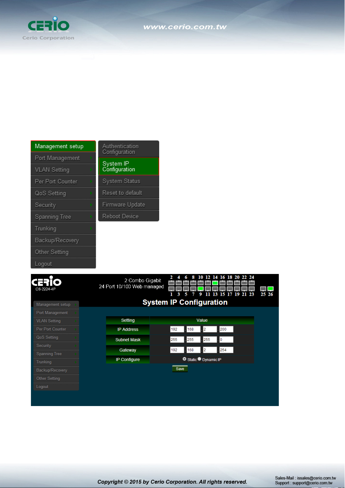
3.2 System IP Configuration
Here are the instructions for how to setup the local IP Address and Netmask.
Please click Management setup System IP Configuration
System IP Configuration : The administrator can manually setup the system IP
address.
IP Address : The IP address of the system; default IP address is 192.168.2.254
Page 16
IP Netmask : The Subnet mask of the system; default Netmask is 255.255.255.0
Gateway : Configure the network gateway address
IP Configure : The administrator can manually setup the system IP address
when static IP is available/ preferred.
Dynamic IP: This configuration type is applicable when the CS-2224-24P is
connected to a network with the presence of a DHCP server; all related IP
information will be provided by the DHCP server automatically.
Click “Save” button to save your changes. Click Reboot button to activate your
changes
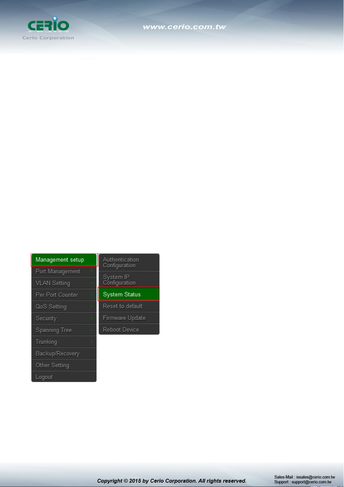
3.3 System Status
MAC address and system version will be shown on the screen. And setting login time out
Please click Management setup System Status
Page 17

MAC Address: MAC address of the display system
Number of Ports: Display CS-2224-24P the Ethernet posts information
Description: Provide description of the system.
Firmware version: Show currently the CS-2224-24P of system software version and
software date
Set login Time out: set Idle Time(1~30 Minutes)
Click “Save” button to save your changes. Click Reboot button to activate your changes
3.4 Reset to default
Please click Management setup Reset to default
Page 18

Recover switch default setting excluding the IP address, User name and
Click Default button to reset back to the factory default settings and expect Successful
loading message. Then, click Reboot button to activate.
Password.
Page 19

3.5 Firmware Update
Firmware is the main software image that system needs to respond to requests and to manage
real time operations. Firmware upgrades are sometimes required to include new features or
bugs fix. It takes around 2 minutes to upgrade due to complexity of firmware. To upgrade
system firmware, click Browse button to locate the new firmware, and then click Upgrade
button to upgrade.
Please click Management setup Firmware Update
Password : Enter administrator password
Do not interrupt during firmware upgrade including power on/off as this
may damage system.
Page 20

3.6 Reboot Device
This function allows user to restart system with existing or most current settings when changes
are made. Click Reboot button to proceed and take around one minute to complete.
Please click Management setup Reboot Device
Page 21

4. Port Management
4.1 Port Configuration
Please click Port Management Port Configuration
Function:
Tx Cap Ability: enable/disable for the selected port.
Auto-Negotiation: enable/disable Auto-Negotiation.
Speed: 10M, 100M or 1000M mode for the selected port.
Duplex: Full or Half-Duplex mode for the selected port.
Pause: enable/disable for the selected port.
Backpressure: enable/disable for the selected port.
Addr. Learning: enable/disable for the selected port.
After press the “ Save ”, the setting of “Port Configuration” is finished.
Page 22

4.2 Port Mirroring
Port Mirroring is used to mirror traffic, RX, TX or TX&RX, from Source port to Destination port
for analysis.
Please click Port Management Port Mirroring
Destination port: you can choose port 1 to port 26.
Source port: by clicking the checking box of the port.
Click “Save” to save the setting.
Page 23

4.3 Bandwidth Control
If the link speed of selected port is lower than the rate that you setting, this system will use the value of
link speed as your setting rate.
Please click Port Management Bandwidth Control
Port No.: you can choose port 1 to port 26.
TX Rate: set the transmission rate of the selected port. (0:Full speed; 1~255:Specified
bandwidth.)
RX Rate: set the receiving rate of the selected port. (0: Full speed; 1~255: Specified
bandwidth.)
Speed Base :
Low: 32Kbps Tx/Rx bandwidth resolution for port 1~ port 26.
(Actual Tx/Rx bandwidth=Rate value x 32 Kbps, The rate value is 1~255.)
High:
1) 256Kbps Tx/Rx bandwidth resolution for port 1~ port 24.
Page 24

(Actual Tx/Rx bandwidth=Rate value x 256 Kbps, The rate value is 1~255.)
2) The bandwidth resolution is 2048Kbps for port 25, port 26.
(Actual Tx/Rx bandwidth=Rate value x 2048 Kbps, The rate value is 1~255.)
Click “Save” to save the setting.
4.4 Broadcast Storm Control
This value indicates the number of broadcast packet which is allowed to enter each port in one
time unit. One time unit is 50us for Gigabit speed, 500 us for 100Mbps speed and 5000us for
10Mbps speed.
Please click Port Management Broadcast Storm Control
Threshold: Set the threshold from 1~63.
Enable Port: Per port to define the status of broadcast packets.
This effect may be not significant for long broadcast packet, since the
broadcast packet count passing through the switch in a time unit is
probably less than the specified number.
Click “Save” to confirm the setting.
Page 25

4.5 PoE
Remote access and monitor the attached PD (Powered Device) status by using
Enable/Disable function.
Please click Port Management PoE Configuration
Enable: POE of the port is able to supply power to the attached PD (Powered Device)
PSE Current & Minimum Output Power: The status of the port current and minimum
output power.
POE class: each POE port will detect the class of the attached PD (Powered Device)
Click “Save” to confirm and finish the setting.
Page 26

5. VLAN Setting
5.1 VLAN Mode
There are two VLAN modes: Port Based VLAN and Tag Based VLAN.
Please click VLAN Setting VLAN mode
Click “Change VLAN mode” button to select the mode.
Click “Next” Enter the settings page.
Page 27

If the Port Based VLAN function is enabled, Tag Based VLAN and Multi
It supports three types of insertion/removal of tags in packet on assigned VLAN Group.
Tag: Insert port's tag for egress packets.
No Change: Don’t change for egress packets.
UnTag: Remove port's tag for egress packets.
1. Link partner is a network interface card; it probably cannot recognize
the VLAN tag. In this case, it is strongly recommended the network
administrator to remove the VLAN tag of the corresponding port.
2.
to 1 setting function will be disabled automatically.
Click “Save” to confirm and finish the setting.
Page 28

5.2 VLAN Member Setting (Tag Based)
You can select a port group.
Please click VLAN Setting VLAN Member
Page 29

VID: Enter a VID, select the VLAN member for this entry and then press this button to add
a VLAN entry to the table.
Delete: Select a VID in the table and then press this button to remove a VID entry from the
table.
Save: Modify the existing VID entry, select VID and then press the button.
If you do not select any port, this VID will be treated as a VID embedded in
a 802.1Q tag.
The Port VID map and tag VLAN Member information.
Page 30

5.3 Multi to 1 Setting
This is a special design for easily setting the switch VLAN into “VLAN per Port“.
Please click VLAN Setting Multi to 1 setting
Destination Port No.: Choose a port of “Destination Port No”.
Current Setting: Display currently set of Destination port No. information
“Disable Port”: choose the port which you don’t want to use
1. Disable port can’t be the same as the destination port
2. After this setting, all ports can only connect to destination ports.
Page 31

6. Per Port Counter
You can read the transmitting and receiving packet of the connecting port.
Please click Per Port Port Counter
Page 32

Counter Mode Selection
Transmit Packet & Receive Packet: Display 1 to 26 ports of Transmit Packet and Receive
Packet information.
Collision Count & Transmit Packet: Display 1 to 26 ports of Collision Count and Transmit
Packet information.
Drop Packet & Receive Packet: Display 1 to 26 ports of Drop Packet and Receive Packet
information.
CRC error Packet & Receive Packet: Display 1 to 26 ports of CRC error Packet and
Receive Packet information
Clear: Clear all the information to recalculate
Refresh: Update the all Information
7. QoS Setting
Quality of Service (QoS) prioritizes network traffic and manages available bandwidth so that
the most important traffic goes first. QoS is implemented as rules or policies that prioritize
packets, optionally change information in the packet header, and assign them to outbound port
queues based on their priority.
7.1 Priority Mode
Each switch port has four types of outbound traffic queues based on priority: First-In-First-Out,
All-High-before-Low and Weight-Round-Robin.
The queue priority determines the order of exit for packets in the queue. For example, packets
in a high priority queue leave the switch before packets in other queues.
Please click QoS Setting Priority Mode
Page 33

There are three Priority Modes to select.
First-in-First-Out: The first receiving packet will be firstly transmitted.
All-High-before-Low: All packets will be assigned to either Q2 (high) piority queue or Q1
(low) priority queue.
Weight-Round-Robin: set the ratio of the transmitting packet for the low priority to high
priority.
When the queue weight is set to "0", it will be treated as "8"
The "low wieght" and "high weight" means the ratio of the packet in the
transmit queue. For example,
If "low weight" and "high weight" are set to "3" and "5", the ratio of the
trasmit packet for the low priority to high priority is 3/5.
Page 34

7.2 Class of Service
You can set QoS mode of per port by different bases.
Please click QoS Setting Port, 802.1p, IP/DS based
As long as any of three COS schemes(802.1p,IP TOS/DS or Port Base) is mapped to "high",
the data packet will be treated as the high priority.
Enable is High Priority
Page 35

7.3 Class of Service Configuration
Please click QoS Setting TCP/UDP Port Based
Base on different protocol, you can choose four different types of Class of Service for each
TCP/UDP port number -First-in-First-out, Discard, High Priority or Law Priority to control the
incoming packet.
The Class of Service for TCP/UDP port number allows the network administrator to assign the
specific application to a priotity queue.
F-I-F-O: The incoming packet will be forwared in first-in-first-out scheme.
Discard: The incoming packet will be discarded at the source port.
Page 36

High: The incoming packet will be forwareded with the high priority.
Low: The incoming packet will be forwareded with the Low priority.
The mask defines which bit is ignored within the IP address bit 0 ~ bit 7.
For example, UDP/TCP port = 65535 and mask = 5,this means 65530, 65531, 65534 and
65535 are all taken into account. UDP/TCP port =65535 and mask=0, this means only
65535 is taken into account.
TCP/UDP Port QoS function: When the "override" item is selected, the Port_based,
Tag_based, IP TOS_based, CoS listed above will be ignored.
Click “Save” to confirm and finish the setting.
8. Security
8.1 MAC address Binding
Set special MAC address to activate on the selected port
Please click Security MAC Address Binding
Page 37

If you setting and enable the binding MAC address in access control list, The port only allow
MAC address on the access control list.
The single port you can setting three MAC address.
MAC Address: Enter MAC address
Select: Select Port to binding MAC address(you can select 1~26 port)
Binding: [Enable] Allow the packet with the specified source MAC address to enter this
port.
Page 38

8.2 Service Protocol Filter
You can enable or disable this function of per port.
Please click Security Service Protocol Filter
Function: setting Disable / Enable the function.
Port Filtering Rule: The outgoing packet with selected protocol will be either forwarded or
dropped at secure WAN port as the figure shown below.
Page 39

"negative" means the selected protocol will be dropped and other protocols will be
forwarded.
"positive" means the selected protocol will be forwarded and other protocol will be
dropped.
Protocol: choose protocols which you want.
Secure WAN Port: choose secure ports which you want.
1. The secure WAN port should be set at the physical port which is
connected to the server.
2. Once this function is enabled, the switch will check the destination
TCP/UTP port number at the outgoing direction of the secure WAN port.
** If the condition matches, this packet will be dropped or forwarded.
3. The description of Secure WAN port is shown on the bottom of this
screen.
Click “Save” to confirm and finish the setting.
Page 40

9. Spanning Tree
Spanning Tree Protocol(STP) allows only one active path at a time between any two network
devices (this prevents the loops) but establishes the redundant links as a backup if the initial link
should fail. If STP costs change, or if one network segment in the STP becomes unreachable, the
spanning tree algorithm reconfigures the spanning tree topology and reestablishes the link by
activating the standby path. Without spanning tree in place, it is possible that both connections
may be simultaneously live, which could result in an endless loop of traffic on the LAN.
9.1 STP Bridge Settings
This setting is to avoid the loop network.
Please click Spanning Tree STP Bridge Setting
Page 41

STP Mode: choose “Disable”, “STP” or “RSTP”
Bridge Priority: Set the priority of the Bridge.
Hello Time: Provides the time period between root bridge configuration messages.
Max Age: Indicates when the current configuration message should be deleted.
Forward Delay: Provides the length of time that bridges should wait before transitioning
to a new state after a topology change. (If a bridge transitions too soon, not all network
links might be ready to change their state, and loops can result.)
Click “Save” to confirm and finish the setting.
9.2 STP Port Setting
Please click Spanning Tree STP Port Setting
Port No.: Choose Port 1 ~ Port 26
Page 42

Priority: Setting 0~ 240
RPC: The RPC= Root Path Cost: 0 = AUTO. When the loop is found, the STP/RSTP will
calculate the cost of its path.
STP Port Status
10. Trunking (Link aggregation)
Link aggregation can aggregate multiple Ethernet ports together to form a logical aggregation
group. To upper layer entities, all the physical links in an aggregation group are a single logical
link.
Link aggregation is designed to increase bandwidth by implementing outgoing/incoming load
sharing among the member ports in an aggregation group. Link aggregation group also allows for
port redundancy, which improves connection reliability.
Page 43

Please click Trunking Link Aggregation Setting
There are two groups to choose and each group is 4 ports and the third group is for 2 ports.
This standard describes the Link Aggregation Control Protocol (LACP), a mechanism for allowing
ports on both sides of a redundant link to configure themselves into a trunk link (aggregate link),
without the need for manual configuration of the ports into trunk groups.
When you enable link aggregation on a group of Brocade ports, the Brocade ports can negotiate
with the ports at the remote ends of the links to establish trunk groups.
Page 44

Member: Choose link group port.
State: Choose Enable / Disable the link group function.
Type: The IEEE 802.3ad Link Aggregation Control Protocol (LACP) enables the dynamic
aggregation of physical links and The Link Aggregation Control Protocol (LACP) is defined in
IEEE 802.3ad. It uses link aggregation control protocol data units (LACPDUs) for information
exchange between LACP-enabled devices. With the usage of preserved fields in LACPDUs,
LACP can deliver extended functions in addition to its basic functions.
Static: switch and switch between must be fixed and setting Link Aggregation
Group(LAG) function.
LACP: switch sides set to LACP mode, The ports on the switch through asking way to
check whether to join LAG, If there to join LAG, LACP connection can be achieved,
otherwise they skipped LACP connection.
Activity: Both switches use “LACP” to configure the Trunk, at least one of them should be
“Active”.
Active:Set the port in this category will take the initiative to ask link port whether the
LACP trunk. If yes, Join the Manage Connections in LACP
Passive:The main can reply to active, and passive connectivity to reach LA CP.
Click “Save” to confirm and finish the setting
Page 45

11. DHCP Relay Agent
11.1 DHCP Relay Agent
Since DHCP clients request IP addresses via broadcast messages, the DHCP server and
clients must be on the same subnet. Therefore, a DHCP server must be available on each
subnet. It is not practical.
DHCP relay agent solves the problem. Via a relay agent, DHCP clients communicate with a
DHCP server on another subnet to obtain configuration parameters. Thus, DHCP clients on
different subnets can contact the same DHCP server for ease of centralized management and
cost reduction.
Please click DHCP Relay Agent DHCP Relay Agent
DHCP Relay State: Select DHCP Relay function Disable or Enable.
DHCP Relay Hops Count Limit (1-16): The maximum numbers of DHCP relay agents
that will handle DHCP relayed traffic. The maximum value is 16 hops.
Page 46

DHCP Relay Option 82 State: The DHCP Information option (Option 82) is commonly
used in metro or large enterprise deployments to provide additional information on
“physical attachment” of the client. Option 82 is supposed to be used in distributed DHCP
server/relay environment, where relays insert additional information to identify the client’s
point of attachment. You can select the function Disable or Enable.
Click “Save” to confirm and finish the setting.
Your DHCP server must be configured to accept DHCP option 82. If the
server is not configured for DHCP option 82, the server does not use the
DHCP option 82 information in the requests sent to it when it formulates its
reply messages
11.2 Relay Server
Enter DHCP Server IP address. Please click DHCP Relay Agent Relay Server
Page 47

Click “Save” to confirm and finish the setting.
11.3 VLAN MAP Relay Agent
Please click DHCP Relay Agent VLAN MAP Relay Agent
Page 48

VLAN ID: Please Enter VLAN 10 number.
Map Server IP: If setting the completed of Relay Server function, The Map server IP you
can select IP address.
Click “Save” to confirm and finish the setting.
12. Backup/Recovery
Please click Trunking Link Aggregation Setting
Page 49

Backup: Click “Download” to confirm the setting.
Recovery: Selects a file and key in the password Click “Update” to confirm the setting.
The Update password is by login password, the login default password is
by “default”
13. Other Setting
Page 50

The function you can setting Aging time / VLAN Striding / and IGMP Snooping etc.
Please click Other Setting
Output Queue Aging Time: Choose Aging time is 200/400/600/800ms or disable etc. The
output queue aging function allows the administrator to select the aging time of a packet
Page 51

stored in the output queue. A packet stored in the output queue for a long time will lower the
free packet buffer, resulting in the poor utilization of the buffer and the poor switch
performance.
VLAN Striding: You can choose VLAN Striding disable or enable function. When this
function is enabled, the switch will forward a uni-cast packet to the destination port. No matter
whether the destination port is in the same VLAN group.
IGMP Snooping V1 & V2: You can choose IGMP Snooping disable or enable function. After
enable IGMP, will use both V1 and V2 function. If enable IGMP Snooping function, you can
choose disable or enable the IGMP Leave Packet. Mainly allows Leave packet will be
forwarded to IGMP router ports.
VLAN Uplink Setting: Set “uplink1 or uplink2” or “Clear uplink1” or “Clear uplink2”
Click “Save” to confirm and finish the setting.
14. Logout
Click “Logout” The system will logout and automatically go to the login page.
Page 52

IEEE 802.3 10Base-T
Specifications
Standards Conformance
Standards & Hardware Specifications
IEEE 802.3u 100Base-TX,
IEEE 802.3ab 1000Base-T, IEEE 802.3z 1000Base-SX/LX
IEEE 802.3x Flow Control
IEEE 802.3af Power over Ethernet ( 15.4 Watt PoE+ )
IEEE 802.3at Power over Ethernet Plus ( 30 Watt PoE+ )
24 ports RJ-45 connectors for 10/100 BASE-TX and PSE/ PoE
Port Configuration
Media Access Protocol
Network Media
Transmission Method
MAC Address Table
Built-in Buffer
Data Transfer Rate
Auto MDI/MDIX
LED Indicators
Internal Bus Speed
Link Aggregation
function
2 port Gigabit Combo SFP/ RJ-45
CSMA / CD
10BASE –T: UTP Cat. 3 or up,
100BASE-TX: UTP Cat. 5 or up,
1000BASE-T: UTP Cat. 5 or up
Store and Forward
4K
3.5Mbits
10/100Mbps (Half-duplex), 20/200Mbps (Full-duplex)
1000Mbps ( Half-duplex), 2000Mbps (Full-Duplex)
Yes
Per Port:(TX): Link/Act , Per Unit: Power
8.8Gbps
Switch Specifications
up to 3 groups and 0-3,4-7 ports ,Gigabit 1-2 ports in each
Priority Queue
Port Mirror
Bandwidth Control
Spanning Tree(STP)
Rapid spanning Tree (RSTP)
IGMP Snooping
MAC Filter
group
IEEE Class of Service ( 4 Queues)
Supported
Supported
Supported
Supported
v1 and v2
Supported
Page 53

380Watt share per Port PoE Device connected) for all ports . AC 90~260VAC, 50-60Hz Auto-sensing
DHCP Relay Agent
VLAN
SNMP
Power Consumption
Power Requirement
Operating Temperature
Storage Temperature
Operating Humidity
Storage Humidity
Dimension ( W x D x H )
Weight
Certification
Supported
IEEE802.1Q Tagging VLAN , Port-Based ,Tag based VLAN
V1 / v2c supported
Environmental & Mechanical Characteristics
15 Watt (max. with no PoE Device connected)
Power Requirement
0° to 50° C
-20° to 90° C
10% to 90% non-condensing
10% to 90% non-condensing
325 x 440 x 44 mm
3.875Kg
FCC, CE, RoHS-compliant
 Loading...