

CERAMATE K300, K250, K240, K220, K200 Datasheet
...
The sidac is a silicon bilateral voltage
handling
capabilities than standard diacs. Upon
application of a voltage exceeding the sidac
switches on
through a negative resistance region to a low
state voltage. Conduction continues until
the current is interrupted or drops below the
CERAMATE offers a voltage range of 95 V to
ERAMATE’s sidacs feature glass passivated
junctions to ensure a rugged and dependable
device capable of withstanding harsh
Variations of devices covered in this data
sheet are available for custom design
more
Silicon Bilateral Voltage Triggered Switch
n Features n General Description
l AC circuit oriented
l Glass-passivated junctions
l High surge current capability
n Applications
l High voltage lamp ignitors
l Natural gas ignitors
SIDAC
K Series
triggered switch with greater power-
breakover voltage point, the sidac
onminimum holding current of the device.
l Gas oil ignitors
l High voltage power supplies
l Xenon ignitors
l Over voltage protector
l Pulse generators
l Fluorescent lighting ignitors
l HID surge current capability
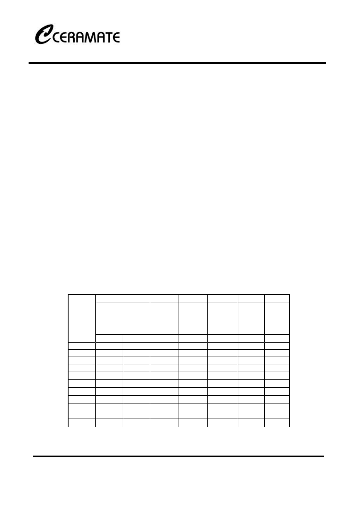
n Electrical Characteristics
VBO V
Breakover Voltage
Part No
K105 95 113 75 10 1.0 100 1.5
K110 104 118 85 10 1.0 100 1.5
K120 110 125 90 10 1.0 100 1.5
K130 120 138 95 10 1.0 100 1.5
K140 130 146 105 10 1.0 100 1.5
K150 140 170 115 10 1.0 100 1.5
K200 190 215 150 10 1.0 100 1.5
K220 205 230 165 10 1.0 100 1.5
K240 220 250 175 10 1.0 100 1.5
K250 240 280 190 10 1.0 100 1.5
K300 270 330 215 10 1.0 100 1.5
(Instantaneous
clamping voltage)
MIN (V) MAX (V) MIN (V) MAX (µA) MAX (A) MAX (mA) MAX (V)
DRM
Blocking
Voltage
330 V in DO-15 package.
C
environments.
applications. Consult the factory for
information.
I
Peak
Off-state
Current at
V
IT IH VTM
DRM
Continuous
DRM
On-state
DC or RMS
Current
Holding
Current
Peak
On-state
Voltage I
=1A
T
* All specs and applications shown above subject to change without prior notice.
1F-5 NO.66 SEC.2 NAN-KAN RD ., LUCHU , TAOYUAN, TAIWAN
Tel:886-3-3214525 Http: www.ceramate.com.tw
Fax:886-3-3521052
Page 1 of 2 Rev 1.1 Sep. 9,2002
Email: server@ceramate.com.tw
SIDAC
K Series
Silicon Bilateral Voltage Triggered Switch
IPP I
Series
K 60 35 35 20 16.7 100
Peak pulse current, TJ <150º C
(10×160µs) (10×560µs) (10×1000µs)
Max (A) Max (A) Max (A) 60Hz (A) 50Hz (A) TYPICAL (A/µs)
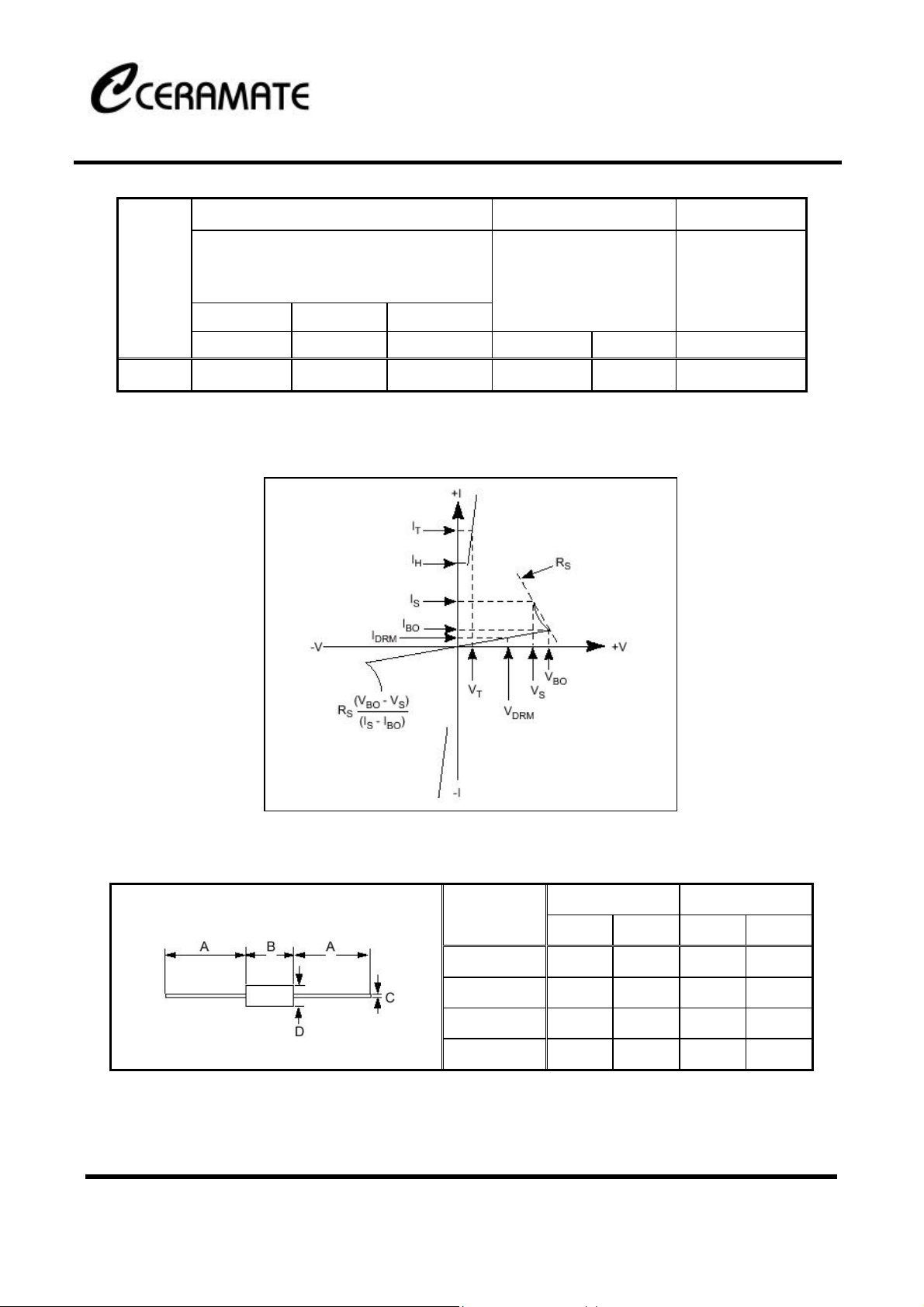
n V-I Characteristics
di/dt
TSM
Peak one
Cycle(sinusoidal) Surge
Current
Critical Rate of
Rise of On-state
Current
n Package Dimensions
K Series / DO-15
Ref
A 1.0 25.4
B 0.22 0.30 5.60 7.60
C 0.028 0.035 0.70 0.90
D 0.10 0.15 2.60 3.80
* All specs and applications shown above subject to change without prior notice.
1F-5 NO.66 SEC.2 NAN-KAN RD ., LUCHU , TAOYUAN, TAIWAN
Tel:886-3-3214525 Http: www.ceramate.com.tw
Fax:886-3-3521052
Page 2 of 2 Rev 1.1 Sep. 9,2002
Inches Millimeters
Min Max Min Max
Email: server@ceramate.com.tw
 Loading...