

Page 1

FA4800
Broadband Wireless Transmission System
USER MANUAL
RELEASES 1.9.30
Page 2

FA4800 User Manual Release 1.9.30 i
FA4800
User Manual
Notice
This document contains information that is proprietary to Ceragon Networks Ltd.
No part of this publication may be reproduced, modified, or distributed without prior written
authorization of Ceragon Networks Ltd. This document is provided as is, without warranty of
any kind.
Registered TradeMarks
Ceragon Networks® is a registered trademark of Ceragon Networks Ltd.
FibeAir® is a registered trademark of Ceragon Networks Ltd.
CeraView® is a registered trademark of Ceragon Networks Ltd.
Other names mentioned in this publication are owned by their respective holders.
TradeMarks
CeraMap™, ConfigAir™, PolyView™, EncryptAir™, CeraMon™, EtherAir™, and MicroW ave
Fiber™, are trademarks of Ceragon Networks Ltd.
Other names mentioned in this publication are owned by their respective holders.
Statement of Conditions
The information contained in this document is subject to change without notice.
Ceragon Networks Ltd. shall not be liable for errors contained herein or for incidental or
consequential damage in connection with the furnishing, performance, or use of this
document or equipment supplied with it.
Information to User
Any changes or modifications of equipment not expressly approved by the manufacturer
could void the user's authority to operate the equipment and the warranty for such
equipment.
Copyright © 2010 by Ceragon Networks Ltd. All rights reserved.
Page 3

FA4800 User Manual Release 1.9.30 ii
Ceragon Worldwide Offices
Corporate Headquarters
Ceragon Networks Ltd.
24 Raoul Wallenberg St.
Tel Aviv 69719, Israel
Tel: 972-3-645-5733
Fax: 972-3-645-5499
Email:
North America
Ceragon Networks Inc.
10 Forest Avenue,
Paramus, NJ 07652, USA
Tel: 1-201-845-6955
Toll Free: 1-877-FIBEAIR
Fax: 1-201-845-5665
Email:
Europe
Ceragon Networks (UK) Ltd.
4 Oak Tree Park, Burnt Meadow Road
North Moons Moat, Redditch,
Worcestershire B98 9NZ, UK
Tel: 44-(0)-1527-591900
Fax: 44-(0)-1527-591903
Email:
APAC -Singapore
Ceragon Networks APAC Pte Ltd.
100 Beach Road
#27-01/03 Shaw Towers
Singapore 189702
Tel: + 65 6572 4170
Fax: +65 6572 4199
Email:
APAC - India
Ceragon Networks (India) Pvt.
Limited
H-9/1, Block B-1,
Mohan Cooperative Industrial Estate,
Mathura Road , NEW DELHI 110044
India
Tel.: 91-..., 91-11-66244700-03
Fax: 91-11-66244704-05
Email: i
MEA
Ceragon Networks (Nigeria) Limited
Block 58A Plot 10
Omorinte Johnson Street
Lekki Phase 1, Lekki Peninsula
Lagos, Nigeria
Email:
CALA
Ceragon Networks S.A de C.V
Minerva 332,
Colonia Florida Delegación Álvaro Obregón
México D.F.
Tel.: 5255 5663 2919
Fax: 5255 5663 2841
General Email:
Technical Support Email:
Page 4

FA4800 User Manual Release 1.9.30 iii
Regulatory Compliance
General Note
This system has achieved Type Approval in various countries around the world. This means
that the system has been tested against various local technical regulations and found to
comply. The frequency bands in which the system operates may be “unlicensed” and in these
bands, the system can be used provided it does not cause interference.
FCC - Compliance
This equipment has been tested and found to comply with the limits for a Class B digital
device, pursuant to Part 15 of the FCC Rules. These limits are designed to provide reasonable
protection against harmful interference in a residential installation. This equipment generates,
uses and can radiate radio frequency energy and, if not installed and used in accordance with
the instructions, may cause harmful interference to radio communications. However, there is
no guarantee that interference will not occur in a particular installation. If this equipment
does cause harmful interference to radio or television reception, which can be determined by
turning the equipment off and on, the user is encouraged to try to correct the interference by
one or more of the following measures:
• Reorient or relocate the receiving antenna.
• Increase the separation between the equipment and receiver.
• Connect the equipment into an outlet on a circuit different from that to which the
receiver is connected.
Consult the dealer or an experienced radio/TV technician for help.
Changes or modifications to this equipment not expressly approved by the party responsible
for compliance could void the user's authority to operate the equipment.
Warning
It is the responsibility of the installer to ensure that when using the outdoor
antenna kits in the United States (or where FCC rules apply), only those
antennas certified with the product are used. The use of any antenna other
than those certified with the product is expressly forbidden by FCC rules 47
CFR part 15.204.
Warning
It is the responsibility of the installer to ensure that when configuring the
radio in the United States (or where FCC rules apply), the Tx power is set
according to the values for which the product is certified. The use of Tx
power values other than those, for which the product is certified, is
expressly forbidden by FCC rules 47 CFR part 15.204.
Caution
Outdoor units and antennas should be installed ONLY by experienced
installation professionals who are familiar with local building and safety
codes and, wherever applicable, are licensed by the appropriate
government regulatory authorities. Failure to do so may void the product
warranty and may expose the end user or the service provider to legal and
financial liabilities. Resellers or distributors of this equipment are not liable
for injury, damage or violation of regulations associated with the installation
of outdoor units or antennas. The installer should configure the output
power level of antennas according to country regulations and antenna type.
Page 5

FA4800 User Manual Release 1.9.30 iv
Indoor Units comply with part 15 of the FCC rules. Operation is subject to the following two
conditions:
(1) These devices may not cause harmful interference.
(2) These devices must accept any interference received, including interference that may
cause undesired operation.
Canadian Emission Requirements for Indoor Units
This Class B digital apparatus complies with Canadian ICES-003.
Cet appareil numrique de la classe B est conforme la norme NMB-003 du Canada.
China MII
Operation of the equipment is only allowed under China MII 5.8GHz band regulation
configuration with EIRP limited to 33 dBm (2 Watt).
India WPC
Operation of the equipment is only allowed under India WPC GSR-38 for 5.8GHz band
regulation configuration.
Unregulated
In countries where the radio is not regulated the equipment can be oper ated in any regulation
configuration, best results will be obtained using Universal regulation configuration.
Safety Practices
Applicable requirements of National Electrical Code (NEC), NFPA 70; and the National
Electrical Safety Code, ANSI/IEEE C2, must be considered during installation.
NOTES:
1. A Primary Protector is not required to protect the exposed wiring as long as the exposed
wiring length is limited to less than or equal to 140 feet, and instructions are provided to
avoid exposure of wiring to accidental contact with lightning and power conductors in
accordance with NEC Sections 725-54 (c) and 800-30.
In all other cases, an appropriate Listed Primary Protector must be provided. Refer to Articles
800 and 810 of the NEC for details.
2. For protection of ODU against direct lightning strikes, appropriate requirements of NFPA
780 should be considered in addition to NEC.
3. For Canada, appropriate requirements of the CEC 22.1 including Section 60 and additional
requirements of CAN/CSA-B72 must be considered as applicable.
Warning
Where Outdoor units are configurable by software to Tx power values other
than those for which the product is certified, it is the responsibility of the
Professional Installer to restrict the Tx power to the certified limits.
Warning
This product was tested with special accessories - indoor unit (IDU or PoE),
FTP CAT-5e shielded cable with sealing gasket, 12 AWG grounding cable which must be used with the unit to insure compliance.
Page 6

FA4800 User Manual Release 1.9.30 v
Brief
Table of Contents
Part 1: Basic Installation
Chapter 1 Introduction
Chapter 2 Site Preparation
Chapter 3 Hardware Installation
Chapter 4 Getting Started with the FibeAir2000 Manager
Chapter 5 Installing the Link
Chapter 6 The FibeAir2000 Manager: Main Window
Chapter 7 Configuring the Link
Chapter 8 Site Configuration
Chapter 9 Monitoring and Diagnostics
Part 2: Site Synchronization
Chapter 10 Hub Site Synchronization
Chapter 11 Reserved
Part 3: Advanced Installation
Chapter 12 Monitored Hot Standby Installation Procedure
Chapter 13 The Ceragon Ethernet Ring
Chapter 14 VLAN Functionality with FA4800
Chapter 15 Software Upgrade
Chapter 16 FCC/IC DFS Installation Procedure
Part 4: Field Installation Topics
Chapter 17 Pole and Wall Installation
Chapter 18 Lightning Protection and Grounding Guidelines
Chapter 19 Preloading an ODU with an IP Address
Chapter 20 Changing the Factory Default Band
Chapter 21 Link Budget Calculator
Part 5: Product Dependent Features
Chapter 22 AIND Alignment
Chapter 23 BRS Installation Procedure
Chapter 24 Cascaded Links
Chapter 25 Video Surveillance
Part 6: Product Reference
Appendix A Technical Specifications
Appendix B Wiring Specifications
Appendix C Small Form-factor Pluggable Transceiver
Appendix D MIB Reference
Appendix E External Alarms Specification
Appendix F RF Exposure
Appendix G Regional Notice: French Canadian
Appendix H Old Style IDU-E Details
Index
Page 7

FA4800 User Manual Release 1.9.30 vi
Full
Table of Contents
Notice.............................................................................................................................i
Ceragon Worldwide Offices...... ........................................................................................ii
Regulatory Compliance.................................................. .................................................iii
Part 1: Basic Installation
Chapter 1 Introduction
Welcome to FA4800! ...................................................................................1-1
About Release 1.9.30...................................................................................1-1
Key Applications..........................................................................................1-2
Cellular Backhaul
......................................................................................1-2
Broadband Access
....................................................................................1-2
Video Surveillance
....................................................................................1-3
Private Networks
......................................................................................1-4
Key Features of FA4800...............................................................................1-4
FA4800 Link................................................................................................1-6
The Outdoor Unit (ODU)
............................................................................1-7
AIND (All Indoor Unit)
..............................................................................1-9
The Indoor Unit (IDU)
...............................................................................1-9
New style IDU-E for both FA4800 and FibeAir 2000..........................................1-9
IDU-R .........................................................................................................1-10
IDU-C .........................................................................................................1-10
Power Over Ethernet (PoE) Devices
............................................................ 1-11
Basic PoE Device..........................................................................................1-11
Antennas
.............................................................................................. 1-12
Flat Panel Antennas .....................................................................................1-13
Parabolic Dish Antennas ...............................................................................1-13
Grid Antennas................................ ..............................................................1-14
FibeAir2000 Manager
..............................................................................1-14
Accessories
...........................................................................................1-15
Documentation supplied with FA4800
......................................................... 1-15
How to Use this Manual.............................................................................1-16
A Little Terminology ..................................................................................1-16
Conventions Used in this Manual ................................................................1-18
Notifications
..........................................................................................1-18
Typographical conventions
.......................................................................1-18
General.......................................................................................................1-18
Software .....................................................................................................1-18
Windows Terminology
.............................................................................1-19
Viewing and Printing
...............................................................................1-20
Chapter 2 Site Preparation
Planning the Link Site............................... .. .. .. .. .. .........................................2-1
Overview
................................................................................................2-1
The Site Survey...........................................................................................2-1
Introduction
............................................................................................2-1
Recommended Equipment
..........................................................................2-1
Stage 1: Preliminary Survey .........................................................................2-2
Stage 2: Physical Survey..............................................................................2-3
Additional Outdoor Site Requirements
...........................................................2-4
Additional Indoor Site Requirements
.............................................................2-4
Stage 3: RF Survey......................................................................................2-4
RF Planning for Dense Installations and Collocated Sites................................2-4
Chapter 3 Hardware Installation
Safety Practices...........................................................................................3-1
Page 8

FA4800 User Manual Release 1.9.30 vii
Preventing overexposure to RF energy
..........................................................3-1
Grounding
...............................................................................................3-1
Protection against Lightning
.......................................................................3-2
General
..................................................................................................3-2
Package Contents........................................................................................3-3
ODU Package Contents
..............................................................................3-3
IDU-E or IDU-R package containing:
............................................................3-4
IDU-C Package Contents
............................................................................3-4
PoE-8 Package Containing:
.........................................................................3-5
External Antenna Package Contents
.............................................................3-5
Additional Tools and Materials Required........................................................3-6
Tools and Materials
...................................................................................3-6
Cables and connectors
...............................................................................3-6
Hardware Installation Sequence ...................................................................3-6
Outdoor installation.....................................................................................3-7
Preparing the ODU before Deployment
.........................................................3-7
Mounting the ODU
....................................................................................3-7
Mounting external antennas
.......................................................................3-8
Mounting the Lightning Protection Devices
....................................................3-8
Outdoor Connections
.................................................................................3-9
Indoor Installation.......................................................................................3-9
Installing IDU-E and R units
.......................................................................3-9
IDU-E Installation ........................ .. .... .. .. .. .. ... .. .... .. .. .. .. .. ... .. .... .. .. .. .. .. ... .... .. .. .. .3-9
IDU-R Installation ............. .. .. ... .... .. .. .. .. .. .. .. ..... .. .. .. .. .. .. ..... .. .. .. .. .. .. .. ..... .. .. .. .. .. .3-9
Mounting the IDU-C
................................................................................3-10
Connecting power to the IDU
....................................................................3-13
Connecting the ODU to the IDU
.................................................................3-13
Installing a Link using PoE Devices
............................................................. 3-13
Connecting User Equipment
......................................................................3-14
Connecting and Aligning ODUs / Antennas ..................................................3-14
Chapter 4 Getting Started with the FibeAir2000 Manager
Installing the FibeAir2000 Manager Application..............................................4-1
Minimum System Requirements
...................................................................4-1
Installing the Software
..............................................................................4-1
Getting Started with the FibeAir2000 Manager...............................................4-2
The FibeAir2000 Manager log-on Concept ................. .. .. .. .. ............................4-3
Log-on Errors and Cautions..........................................................................4-6
Unsupported Device
..................................................................................4-6
Incorrect IP Address
.................................................................................4-6
Incorrect Password
...................................................................................4-7
Invalid Read/Write Community String
...........................................................4-7
Logging in to the Over-the-Air Site
...............................................................4-7
Continuing without an IP Address............ .. .. .. .... .. ... ......................................4-7
Changing the Log-On Password
...................................................................4-8
First steps...................................................................................................4-8
Default FA4800 Settings
..........................................................................4-11
Chapter 5 Installing the Link
Overview....................................................................................................5-1
Installation .................................................................................................5-3
Step 1, Start the Wizard ....................... .. .. .. .. .. .. ...........................................5-3
Step 2, System Parameters ............................ .. .. ... .. ....................................5-3
Changing the Link Password
.......................................................................5-5
Step 3, Channel Settings .............................. .. .. .. ... ......................................5-7
Step 4, Hub Site Synchronization Settings .................... .. ..............................5-9
Step 5, Services ..... ....................................................................................5-9
TDM Services selection
............................................................................5-10
Page 9

FA4800 User Manual Release 1.9.30 viii
Modulation Rate Selection
........................................................................5-12
Setting Monitored Hot Standby Mode
......................................................... 5-13
Ethernet Ring
........................................................................................5-14
Setting the TDM Jitter Buffer
....................................................................5-14
Step 6, TDM Clock Configuration .............. .. .. .............................................5-16
Step 7, Installation Summary and Exit .......................................................5-18
Chapter 6 The FibeAir2000 Manager: Main Window
One Manager for all Ceragon Radio Products.................................................6-1
The Main Window of the FibeAir2000 Manager..............................................6-1
The FibeAir2000 Manager Toolbar ......... .. .. .. .. .. .............................................6-2
Main Menu Functionality ..............................................................................6-3
Elements of the FibeAir2000 Manager Main Window ......................................6-4
Chapter 7 Configuring the Link
Overview....................................................................................................7-1
Configuration..............................................................................................7-3
Step 1, Start the Wizard ....................... .. .. .. .. .. .. ...........................................7-3
Step 2, System Parameters ............................ .. .. ... .. ....................................7-3
Step 3, Channel Settings .............................. .. .. .. ... ......................................7-4
Step 4, Hub Site Synchronization Settings .................... .. ..............................7-8
Step 5, Services ..... ....................................................................................7-8
Step 6, TDM Clock Configuration .............. .. .. ...............................................7-9
Step 7, Configuration Summary and Exit ....................................................7-10
Chapter 8 Site Configuration
Configuring the Site................................ .. .. .. ...............................................8-1
Editing the Configuration Parameters by Site
..................................................8-1
Functions on the left of the dialog box:............................................................8-2
Functions at the top of the dialog box: ............................................................8-2
Viewing System Details................................................................................8-3
Viewing Air Interface Details ........................................................................8-3
Hub Site Sync .............................................................................................8-4
Site Management: IP Address, VLAN and Protocol .........................................8-5
Configuring the ODU Address
......................................................................8-5
Configuring VLAN Settings
..........................................................................8-6
Lost or forgotten VLAN ID
..........................................................................8-8
Enable / Disable Telnet Access
....................................................................8-8
Displaying the Inventory............................................ ..................................8-8
Security Features ........................................................................................8-9
Changing the Link Password
.....................................................................8-10
FibeAir2000 Manager Community Strings
....................................................8-10
Editing Community Strings............................................................................8-10
Forgotten Community string .........................................................................8-11
Link Lock Security Feature
........................................................................8-11
Setting the Date and Time .........................................................................8-13
Ethernet Properties....................................................................................8-15
Configuring the Bridge
.............................................................................8-15
ODU Mode.............. .. .. .. .... .. .. ... .. .. .. .. .... .. .. .. ... .. .. .... .. .. .. .. ... .. .. .... .. .. .. .. ... .. .... .. .8-16
IDU Aging time........................................ ....................................................8-16
Configuring Ethernet Ports Mode
...............................................................8-17
VLAN Tagging for Ethernet Service: Configuration
.........................................8-18
Setting the Maximum Information Rate (MIR)
..............................................8-19
What is the MIR.......................................................................................... .8-19
What is it for .............................................................................................. .8-19
TDM MHS Status.......................................................................................8-21
Setting External Alarm Inputs.....................................................................8-21
Resetting..................................................................................................8-22
Page 10

FA4800 User Manual Release 1.9.30 ix
IDU Detection.......................... .. .. .............................................................8-23
Backup/Restore of ODU Software Files...................... .. .. .. .. ..........................8-24
Backup ODU Software to a File
..................................................................8-24
Restoring ODU Software or Configuration
....................................................8-24
Muting the alignment tone buzzer...............................................................8-25
Configuration with Telnet...........................................................................8-25
Chapter 9 Monitoring and Diagnostics
Retrieving Link Information (Get Diagnostics)................................................9-1
Link Compatibility............ .. .. .. ......................................................................9-2
TDM Loopbacks...........................................................................................9-3
Local Line Loopback
..................................................................................9-6
Remote Reverse Loopback
.........................................................................9-6
Remote Line Loopback
..............................................................................9-6
Local Internal Loopback
.............................................................................9-7
Reinstalling and Realigning a Link.................................................................9-7
The Link Budget Calculator ................... .. .. ...................................................9-8
Performance Monitoring........................ .. .. ...................................................9-8
The Monitor Log
.......................................................................................9-8
Saving the Monitor Log....................................................... ............................9-8
Viewing Performance Reports ........................................................................ .9-9
Performance Monitoring Report Toolbar..................................... ....................9-12
Setting Air Interface Thresholds....................................................................9-12
Events, Alarms and Traps ..........................................................................9-14
The Events Log
......................................................................................9-14
FibeAir2000 Manager Traps
......................................................................9-16
Setting the Events Preferences
..................................................................9-17
Saving the Events Log
.............................................................................9-17
Active Alarms
........................................................................................9-18
Viewing Recent Events
............................................................................9-18
Reverting Alert Messages...........................................................................9-19
Other Advanced Preferences ...................................................................... 9-20
Setting the FibeAir2000 Manager Language
.................................................9-20
Setting SNMP Parameters
.........................................................................9-20
Remote Power Fail Indication..................................................................... 9-20
Troubleshooting........................................................................................9-20
Replacing an ODU .....................................................................................9-21
Restoring Factory Setup........................ .. .. .. .. .. ...........................................9-22
Online Help...............................................................................................9-22
Customer Support .....................................................................................9-22
Part 2: Site Synchronization
Chapter 10 Hub Site Synchronization
What is Hub Site Synchronization?............................ .. .. .. .. .. .. ......................10-1
Hardware Installation ................................................................................10-3
Connecting an HSS Unit
...........................................................................10-3
Using a Single HSS Unit
...........................................................................10-4
Using More than One HSS Unit
..................................................................10-5
Condition 1: Cabling Sequence......................................................................10-5
Condition 2: Total HSS Cable Length .............................................................10-6
HSS Error Notification..................................... ...........................................10-7
ODU/HSS Unit Connection Pinout ...............................................................10-7
Radio Frame Pattern (RFP).........................................................................10-7
Without HSS
..........................................................................................10-7
RFP and HSS
.........................................................................................10-8
RFP: General Radio Frame Pattern
............................................................. 10-9
RFP: FibeAir 2000 Considerations
..............................................................10-9
RFP: FA4800 Considerations
................................................................... 10-12
Page 11

FA4800 User Manual Release 1.9.30 x
HSS Status LED on the IDU-C and New Style IDU-E................................... 10-13
Link Configuration and HSS..................... .. .. .. .. ......................................... 10-13
Site Configuration and HSS ......... .. .. ......................................................... 10-15
Chapter 11 Reserved
Part 3: Advanced Installation
Chapter 12 Monitored Hot Standby Installation Procedure
What is a Ceragon Monitored Hot Standby ................ .. .. .. .. .. ........................12-1
What Ceragon MHS provides...................................................................... 12-2
Equipment Protection
..............................................................................12-2
Air-Interface Protection
............................................................................12-2
Purpose of this Chapter .............................................................................12-3
Who Should Read this ...............................................................................12-3
Ceragon MHS Kit Contents.........................................................................12-3
Installing a Ceragon MHS . ..........................................................................12-3
Maintaining a Ceragon MHS Link ................................................................12-9
IDU Replacement
...................................................................................12-9
ODU Replacement
................................................................................ 12-10
Switching Logic....................................................................................... 12-11
Switching from Primary Link to Secondary Link
........................................... 12-11
Switching back from the Secondary to the Primary Link
................................ 12-12
System Operation description
.................................................................12-14
Chapter 13 The Ceragon Ethernet Ring
Scope.......................................................................................................13-1
What is an Ethernet Ring........................ .. .. ...............................................13-1
Some terminology:
.................................................................................13-1
Ceragon Ethernet Ring...............................................................................13-2
Ethernet Ring Topologies Supported by Ceragon ......................................... 13-4
Protection Switching..................................................................................13-5
Hardware Considerations ...........................................................................13-5
Special Case: 1 + 1 Ethernet Redundancy...................................................13-6
Using FibeAir2000 Manager to Set up a Ring...............................................13-7
Chapter 14 VLAN Functionality with FA4800
VLAN Tagging - Overview .... .. ... .. .. .. ...........................................................14-1
VLAN Terminology
..................................................................................14-1
VLAN Background Information on the WEB
..................................................14-1
VLAN Tagging
........................................................................................14-1
QinQ (Double Tagging) for Service Providers
...............................................14-2
VLAN Untagging
.....................................................................................14-2
Port Functionality
...................................................................................14-2
Ingress Direction..........................................................................................14-4
Egress Direction...........................................................................................14-4
VLAN Availability ....................................................................................... 14-6
VLAN Configuration Using the FibeAir2000 Manager.....................................14-6
Management Traffic and Ethernet Service Separation
....................................14-7
VLAN Tagging for Ethernet Service: Configuration
.........................................14-7
Chapter 15 Software Upgrade
What is the Software Upgrade Utility?.........................................................15-1
Upgrading an Installed Link........................................................................ 15-1
Chapter 16 FCC/IC DFS Installation Procedure
FCC/IC 5.4/5.3 GHz Links: Background .......................................................16-1
FCC/IC 5.4/5.3 GHz Link Activation.............................................................16-1
FCC/IC 5.4/5.3 GHz Link Configuration........................................................16-4
Part 4: Field Installation Topics
Chapter 17 Pole and Wall Installation
Page 12

FA4800 User Manual Release 1.9.30 xi
ODU Mounting Kit Contents........................................................................17-1
Mounting an ODU on a Pole .......................................................................17-2
Mounting an ODU on a Wall.......................................................................17-3
Mounting an External Antenna ...................................................................17-3
Mounting a Connectorized ODU Horizontally................................................17-4
Chapter 18 Lightning Protection and Grounding Guidelines
Grounding for Antenna Cable .......... .. .. .......................................................18-1
Grounding for Indoor/Outdoor Units ...........................................................18-2
ODU Grounding
......................................................................................18-2
IDU Grounding
.......................................................................................18-2
External Lightning Surge Suppressors and Grounding...................................18-3
Internal ESD Protection circuits ..................................................................18-7
Chapter 19 Preloading an ODU with an IP Address
Why this is Needed?......................................... .........................................19-1
Required Equipment..................................................................................19-1
The procedure ...................... ... .. .. .. ...........................................................19-2
Tip: How to Recover a Forgotten ODU IP Address .......................................19-6
Chapter 20 Changing the Factory Default Band
Why this is Needed................ ... .. .. .. .. .. .......................................................20-1
Required Equipment..................................................................................20-1
The procedure ...................... ... .. .. .. ...........................................................20-1
Changing Band for DFS..............................................................................20-5
Special Products or Features: Entering a License Key ...................................20-5
Chapter 21 Link Budget Calculator
Overview.................................................................................................. 21-1
User Input
............................................................................................ 21-1
Link Budget Calculator Internal Data
.......................................................... 21-1
Calculations ..............................................................................................21-2
EIRP
....................................................................................................21-2
Expected RSS and Fade Margin
.................................................................21-2
Min and Max Range
................................................................................21-2
Service
.................................................................................................21-2
Availability
............................................................................................ 21-2
Antenna Height
......................................................................................21-3
About the Fresnel Zone..............................................................................21-3
Running the Link Budget Calculator ....... .. .. .. .. .... .. ... .................................... 21-5
Part 5: Product Dependent Features
Chapter 22 AIND Alignment
Expected Signal Level for AIND radios ........................................................22-1
Performing FA4800 AIND Alignment ...........................................................22-2
Equipment Setup
....................................................................................22-2
Aligning the antennas
..............................................................................22-2
Configuring the Link............ ........................................ .................................22-3
Evaluating the Link................... .. .. .. .. .. .. .. .... ... .. .. .. .. .. .... .. ... .. .. .. .. .. .... .. ... .. .. .. .. .22-3
Troubleshooting...........................................................................................22-3
Chapter 23 BRS Installation Procedure
BRS Link Activation................ ... ................................................................. 23-1
BRS Link Configuration .. .. .. .. .. ... .. .. .. .. .........................................................23-3
Chapter 24 Cascaded Links
About the Ceragon Cascaded Links.............................................................24-1
Installing Cascaded Links...........................................................................24-1
Chapter 25 Video Surveillance
About the Ceragon Video Surveillance Product.............................................25-1
Installation ...............................................................................................25-1
Page 13

FA4800 User Manual Release 1.9.30 xii
Part 6: Product Reference
Appendix A Technical Specifications
Scope of these Specifications .......................................................................A-1
ODU...........................................................................................................A-1
IDU...........................................................................................................A-3
PoE Device - Indoor, AC.................... .. .........................................................A-5
PoE Device - Outdoor, DC............................. .. .. .. ... ......................................A-6
Antenna Characteristics ...............................................................................A-7
Appendix B Wiring Specifications
ODU-IDU Cable...........................................................................................B-1
ODU/HSS Unit Connection Pinout .................................................................B-1
User Port Connectors..................................................................................B-2
LAN Port
.................................................................................................B-2
LAN Port for PoE-8
....................................................................................B-2
O-PoE to PC LAN Cable
..............................................................................B-2
Trunk Ports - E1/T1 RJ45 Connector
............................................................B-3
Hot Standby Port RJ-11
.............................................................................B-3
IDU (all models) Alarm Connector
................................................................B-3
DC Power Terminals....................................................................................B-5
IDU-C & E
...............................................................................................B-5
DC PoE
...................................................................................................B-5
Appendix C Small Form-factor Pluggable Transceiver
IDU-C SFP Support......................................................................................C-1
Appendix D MIB Reference
Introduction............................................................................................... D-1
About the MIB
........................................................................................ D-1
Terminology
........................................................................................... D-1
Interface API ............................................................................................. D-1
Control Method
....................................................................................... D-1
Community String
.................................................................................... D-2
Private MIB Structure ............... .. .. .. .. .. .. ...................................................... D-2
MIB Parameters ......................................................................................... D-3
Supported Variables from the RFC 1213 MIB
................................................. D-4
MIB Parameters
...................................................................................... D-6
MIB Traps.................................................................................................D-23
General
................................................................................................D-23
Trap Parameters
....................................................................................D-24
FibeAir2000 Manager Traps........... .. .. .. .. .. .. .................................................D-28
Appendix E External Alarms Specification
External Alarms Specification........................................................................E-1
IDU-C and new style IDU-E Alarms
..............................................................E-1
IDU-E-AL Alarms
......................................................................................E-2
PoE-8 Alarms
...........................................................................................E-3
Appendix F RF Exposure
Appendix G Regional Notice: French Canadian
Procédures de sécurité ............................................................................... G-1
Généralités
............................................................................................. G-1
Mise à la terre
........................................................................................ G-1
Protection contre la foudre
........................................................................ G-2
Précautions de sécurité pendant le montage de ODU
...................................... G-2
Connecter la terre à IDU-C
........................................................................ G-3
Installation sur pylône et mur...................................................................... G-3
Contenu du kit de montage ODU
................................................................ G-3
Montage sur un pylône
............................................................................. G-4
Montage sur un mur
................................................................................ G-5
Page 14

FA4800 User Manual Release 1.9.30 xiii
Montage d'une antenne externe
................................................................. G-6
Contenu du kit de montage d'une antenne externe
........................................ G-6
Appendix H Old Style IDU-E Details
Index
Page 15

FA4800 User Manual Release 1.9.30 xiv
List of Figures
FIGURE 1-1 TYPICAL CELLULAR BACKHAUL APPLICATION...............................................1-2
F
IGURE 1-2 TYPICAL BROADBAND ACCESS APPLICATION...............................................1-3
F
IGURE 1-3 TYPICAL WIFI BACKHAUL APPLICATION....................................................1-3
F
IGURE 1-4 MULTI POINT-TO-POINT VIDEO SURVEILLANCE DEPLOYMENT.........................1-3
F
IGURE 1-5 PRIVATE NETWORK .............................................................................1-4
F
IGURE 1-6 MULTI POINT-TO-POINT ENTERPRISE CONNECTIVITY...................................1-4
F
IGURE 1-7 EXAMPLE OF LINK ARCHITECTURE - SYSTEM COMPONENTS............................1-6
F
IGURE 1-8 ODU FORM FACTORS ..........................................................................1-7
F
IGURE 1-9 AIND - “ALL INDOOR” UNIT CONNECTED TO ANTENNA ................................1-9
F
IGURE 1-10 NEW STYLE IDU-E - FRONT VIEW (NOTE NEW HSS LED ON THE LEFT).........1-9
F
IGURE 1-11 NEW STYLE IDU-E: REAR PANEL ........................................................1-10
F
IGURE 1-12 IDU-R REAR PANEL ........................................................................1-10
F
IGURE 1-13 BACKUP LINK FOR E1/T1 CONNECTIONS...............................................1-10
F
IGURE 1-14 IDU-C, ETHERNET ONLY, FRONT PANEL................................................1-11
F
IGURE 1-15 IDU-C, 4 E1/T1 PORTS, FRONT PANEL................................................1-11
F
IGURE 1-16 BASIC POE DEVICE - SHOWING THE RADIO ETHERNET PORT ...................... 1-11
F
IGURE 1-17 RUGGEDIZED DC-POE DEVICE: INPUT IS -20 TO -60 VDC (SINGLE INPUT)..1-12
F
IGURE 1-18 O-POE DEVICE: INPUT IS MAINS AC POWER.......................................... 1-12
F
IGURE 1-19 POE-8 UNIT..................................................................................1-12
F
IGURE 1-20 ODU WITH INTEGRATED ANTENNA (SIDE AND FRONT VIEWS)..................... 1-13
F
IGURE 1-21 EXTERNAL ANTENNAS - FLAT PANEL.....................................................1-13
F
IGURE 1-22 EXTERNAL ANTENNAS - PARABOLIC DISH ..............................................1-13
F
IGURE 1-23 EXTERNAL ANTENNAS - GRID ANTENNA ................................................1-14
F
IGURE 1-24 FIBEAIR2000 MANAGER WINDOW.......................................................1-15
F
IGURE 1-25 MENU NAVIGATION IN THE FIBEAIR2000 MANAGER ................................ 1-19
F
IGURE 1-26 SITE CONFIGURATION WINDOW WITH OPEN MANAGEMENT PANEL ...............1-20
F
IGURE 3-1 ODU MOUNTING KIT...........................................................................3-3
F
IGURE 3-2 CONNECTORIZED ODU - FRONT AND REAR VIEWS ......................................3-3
F
IGURE 3-3 INTEGRATED ODU - FRONT AND REAR VIEWS............................................3-4
F
IGURE 3-4 IDU-E/R - FRONT VIEW.......................................................................3-4
F
IGURE 3-5 IDU-C PACKAGE CONTENTS - THE IDU-C, ETHERNET ONLY..........................3-4
F
IGURE 3-6 IDU-C PACKAGE CONTENTS - THE IDU-C, 4 E1/T1 PORTS..........................3-5
F
IGURE 3-7 IDU-C PACKAGE CONTENTS - THE MOUNTING KIT AND DC POWER PLUGS .........3-5
F
IGURE 3-8 POE-8 UNIT......................................................................................3-5
F
IGURE 3-9 TYPICAL INSTALLATION (WITH EXTERNAL ANTENNA) LEFT: FIBEAIR 2000 RIGHT: FA4800
3-7
F
IGURE 3-10 NEW STYLE IDU-E: REAR PANEL ..........................................................3-9
F
IGURE 3-11 IDU-R REAR PANEL ..........................................................................3-9
F
IGURE 3-12 IDU-C FRONT PANEL .......................................................................3-10
F
IGURE 3-13 IDU-C - A PERSPECTIVE VIEW ...........................................................3-10
F
IGURE 3-14 IDU-C FRONT PANEL LEDS ..............................................................3-11
F
IGURE 3-15 IDU-E FRONT PANEL LEDS .............................................................. 3-11
F
IGURE 3-16 IDU-C POWER CONNECTORS .............................................................3-13
F
IGURE 3-17 BEEP SEQUENCE FOR ANTENNA ALIGNMENT............................................3-15
F
IGURE 4-1 LAN PORTS ON THE FRONT PANEL OF THE IDU-C.......................................4-2
F
IGURE 4-2 PINGING AN UNINSTALLED AND UNCONFIGURED LINK ...................................4-3
F
IGURE 4-3 FIRST TIME LOG-ON WINDOW ................................................................4-3
F
IGURE 4-4 LOG ON WINDOW EXPOSING THE USER TYPES. ...........................................4-4
F
IGURE 4-5 UNSUPPORTED DEVICE MESSAGE.............................................................4-6
F
IGURE 4-6 UNREACHABLE DEVICE MESSAGE .............................................................4-6
F
IGURE 4-7 INVALID COMMUNITY STRING MESSAGE....................................................4-7
F
IGURE 4-8 LOGGING ON TO AN OVER-THE-AIR SITE ...................................................4-7
Page 16

FA4800 User Manual Release 1.9.30 xv
F
IGURE 4-9 OPENING FIBEAIR2000 MANAGER WINDOW PRIOR TO INSTALLATION - IDU-C AND NEW
STYLE IDU-E.........................................................................................................4-9
F
IGURE 4-10 OPENING FIBEAIR2000 MANAGER WINDOW PRIOR TO INSTALLATION - OLD STYLE IDU-E
4-9
F
IGURE 5-1 LINK INSTALLATION WIZARD .................................................................5-3
F
IGURE 5-2 INSTALLATION WIZARD, SYSTEM DIALOG BOX............................................5-4
F
IGURE 5-3 INSTALLATION WIZARD, SYSTEM DIALOG BOX FILLED OUT ............................5-5
F
IGURE 5-4 CHANGE LINK PASSWORD DIALOG BOX.....................................................5-6
F
IGURE 5-5 LOST OR FORGOTTEN LINK PASSWORD RECOVERY.......................................5-6
F
IGURE 5-6 CHANNEL SETTINGS - AUTOMATIC CHANNEL SELECTION...............................5-7
F
IGURE 5-7 CHANNEL SETTINGS - SHOWING AVAILABLE INSTALLATION RATES ...................5-8
F
IGURE 5-8 CHANNEL SETTINGS - SHOWING AVAILABLE CHANNEL BANDWIDTHS ................5-8
F
IGURE 5-9 HSS SETTINGS ..................................................................................5-9
F
IGURE 5-10 SERVICES AND RATES .....................................................................5-10
F
IGURE 5-11 TDM SERVICE PORT SELECTION..........................................................5-11
F
IGURE 5-12 TDM SERVICE PORT SELECTION - SEVEN SERVICES SELECTED.....................5-11
F
IGURE 5-13 SERVICES AND RATES - SERVICES CHOSEN ............................................5-12
F
IGURE 5-14 SERVICES AND RATES DIALOG: AVAILABLE RATES....................................5-12
F
IGURE 5-15 CHOOSING HOT STANDBY MODE ........................................................5-13
F
IGURE 5-16 TDM JITTER BUFFER CONFIGURATION.................................................5-14
F
IGURE 5-17 TDM JITTER BUFFER CONFIGURATION - ETBE EVALUATION BAR................5-15
F
IGURE 5-18 SERVICES AND TDM DELAY SET - LINK READY FOR EVALUATION .................5-15
F
IGURE 5-19 TDM PARAMETERS CONFIGURATION (1)............................. .. .. .. .. .. ........5-16
F
IGURE 5-20 TDM PARAMETERS..........................................................................5-17
F
IGURE 5-21 INSTALLATION WIZARD EXIT SUMMARY ................................................5-18
F
IGURE 5-22 MAIN WINDOW OF THE MANAGER AFTER INSTALLATION WITH LOADED TRUNKS5-19
F
IGURE 6-1 MAIN WINDOW, WIRELESS LINK IS ACTIVE..............................................6-2
F
IGURE 7-1 LINK CONFIGURATION WIZARD ..............................................................7-3
F
IGURE 7-2 CONFIGURATION WIZARD, SYSTEM DIALOG BOX.........................................7-4
F
IGURE 7-3 CHANNEL SETTINGS DIALOG BOX - AUTOMATIC CHANNEL SELECTION...............7-5
F
IGURE 7-4 SEARCHING FOR THE BEST OPERATING CHANNEL.........................................7-6
F
IGURE 7-5 CHANNEL SETTINGS WITHOUT AUTOMATIC CHANNEL SELECTION .....................7-6
F
IGURE 7-6 CHANNEL FREQUENCY OPTIONS...............................................................7-7
F
IGURE 7-7 CHOOSING AN “OTHER” OPERATING CHANNEL FREQUENCY............................7-7
F
IGURE 7-8 HSS SETTINGS ..................................................................................7-8
F
IGURE 7-9 SERVICES AND RATES DIALOG................................................................7-9
F
IGURE 7-10 TDM PARAMETERS CONFIGURATION.................................................... 7-10
F
IGURE 7-11 CONFIGURATION WIZARD EXIT SUMMARY.............................................7-10
F
IGURE 7-12 MAIN WINDOW OF THE MANAGER AFTER CONFIGURATION..........................7-11
F
IGURE 8-1 CONFIGURATION DIALOG BOX................................................................8-2
F
IGURE 8-2 AIR INTERFACE DETAILS .......................................................................8-3
F
IGURE 8-3 HSS STATUS.....................................................................................8-5
F
IGURE 8-4 MANAGEMENT ADDRESSES - SITE CONFIGURATION DIALOG BOX .....................8-6
F
IGURE 8-5 CONFIGURING MANAGEMENT TRAFFIC VLAN SETTINGS.................................8-8
F
IGURE 8-6 ENABLE/DISABLE TELNET ACCESS...........................................................8-8
F
IGURE 8-7 INVENTORY WINDOW...........................................................................8-9
F
IGURE 8-8 AVAILABLE SECURITY FEATURES..............................................................8-9
F
IGURE 8-9 CHANGING THE COMMUNITY STRING .....................................................8-11
F
IGURE 8-10 ALTERNATIVE COMMUNITY DIALOG BOX................................................8-11
F
IGURE 8-11 DATE AND TIME CONFIGURATION ....................................................... 8-14
F
IGURE 8-12 CHANGE DATE AND TIME..................................................................8-15
F
IGURE 8-13 DATE AND TIME CONFIGURED FROM AN NTP SERVER ..............................8-15
F
IGURE 8-14 BRIDGE, VLAN AND MIR CONFIGURATION............................................8-16
F
IGURE 8-15 VLAN TAG SETTINGS .......................................................................8-18
Page 17

FA4800 User Manual Release 1.9.30 xvi
F
IGURE 8-16 BRIDGE CONFIGURATION - SITE CONFIGURATION DIALOG BOX...................8-20
F
IGURE 8-17 ETHERNET MIR - THROUGHPUT SELECTION...........................................8-20
F
IGURE 8-18 TDM MHS STATUS .........................................................................8-21
F
IGURE 8-19 EXTERNAL ALARMS CONFIGURATION .................................................... 8-22
F
IGURE 8-20 SITE CONFIGURATION - RESET TO FACTORY DEFAULTS .............................8-23
F
IGURE 8-21 ALIGNMENT TONE BUZZER STATES .......................................................8-25
F
IGURE 8-22 TELNET SESSION LOG ON ..................................................................8-26
F
IGURE 8-23 TELNET MANAGEMENT WINDOW..........................................................8-27
F
IGURE 9-1 GET DIAGNOSTICS DIALOG BOX.............................................................9-2
F
IGURE 9-2 LOOPBACK CONFIGURATION BOX .............................................................9-4
F
IGURE 9-3 LOOPBACK CONFIGURATION BOX WITH ONE SITE A PORT SELECTED.................9-4
F
IGURE 9-4 LOOPBACK OPTIONS.............................................................................9-4
F
IGURE 9-5 LOOPBACK DEFINED.............................................................................9-5
F
IGURE 9-6 SITE A PORT 2 SET TO LOOPBACK...........................................................9-5
F
IGURE 9-7 LOCAL LINE LOOPBACK.........................................................................9-6
F
IGURE 9-8 REMOTE REVERSE LOOPBACK.................................................................9-6
F
IGURE 9-9 REMOTE LINE LOOPBACK ......................................................................9-7
F
IGURE 9-10 LOCAL REVERSE LOOPBACK .................................................................9-7
F
IGURE 9-11 PREFERENCES DIALOG BOX ..................................................................9-9
F
IGURE 9-12 BASIC PERFORMANCE MONITORING REPORT ..........................................9-10
F
IGURE 9-13 A TYPICAL PERFORMANCE MONITORING REPORT BASED ON 15 MINUTE INTERVALS9-10
F
IGURE 9-14 PERFORMANCE MONITORING REPORT SHOWING THE EFFECT OF A RESET......9-11
F
IGURE 9-15 THRESHOLD CONFIGURATION DIALOG BOX.............................................9-13
F
IGURE 9-16 EVENTS LOG DISPLAY ......................................................................9-15
F
IGURE 9-17 PREFERENCES DIALOG BOX - EVENT TAB ...............................................9-17
F
IGURE 9-18 ACTIVE ALARMS SUMMARY ................................................................9-18
F
IGURE 9-19 RECENT EVENTS - UP TO LAST 256 EVENTS AT SITE A............................9-19
F
IGURE 9-20 ADVANCED PREFERENCES .................................................................. 9-19
F
IGURE 10-1 INTERFERENCE CAUSED BY COLLOCATED UNITS .......................................10-2
F
IGURE 10-2 COLLOCATED UNITS USING HUB SITE SYNCHRONIZATION (1) ....................10-2
F
IGURE 10-3 COLLOCATED UNITS USING HUB SITE SYNCHRONIZATION (2) ....................10-2
F
IGURE 10-4 HSS INTERCONNECTION UNIT............................................................10-3
F
IGURE 10-5 HSS WIRING SCHEMATIC..................................................................10-4
F
IGURE 10-6 HSS SYNC SIGNAL PATH WITH ODU 1 AS HSS MASTER...........................10-5
F
IGURE 10-7 CASCADING TWO HSS UNITS.............................................................10-5
F
IGURE 10-8 CASCADING THREE HSS UNITS...........................................................10-6
F
IGURE 10-9 ODU BEEP FOR HSS ERROR..............................................................10-7
F
IGURE 10-10 RADIO FRAME PATTERN..................................................................10-8
F
IGURE 10-11 SERVICES AND RATES - FIBEAIR 2000 100 MASTER, FIBEAIR 2000 CLIENTS10-10
F
IGURE 10-12 SERVICES AND RATES - FIBEAIR 2000 100 MASTER, FIBEAIR 2000 CLIENTS - EXTREME
ASYMMETRIC ALLOCATION...................................................................................... 10-11
F
IGURE 10-13 HSS SETTINGS: LEFT - FA4800 CLIENT, RIGHT - FIBEAIR 2000 MASTER 10-13
F
IGURE 10-14 HUB SITE CONFIGURATION DIALOG - LEFT FA4800, RIGHT FIBEAIR 200010-15
F
IGURE 10-15 SITE CONFIGURATION: HSS - LEFT - FA4800 CLIENT, RIGHT - FIBEAIR 2000 MASTER
10-15
F
IGURE 10-16 HSS NOT SUPPORTED.................................................................. 10-16
F
IGURE 12-1 CERAGON MONITORED HOT STANDBY..................................................12-1
F
IGURE 12-2 CERAGON Y-CONNECTION PATCH PANEL ...............................................12-3
F
IGURE 12-3 HOW TO CONNECT THE IDUS TO THE PATCH PANEL................................ 12-4
F
IGURE 12-4 SERVICES CONFIGURATION PANEL: HOT STANDBY MODE SELECTION............12-5
F
IGURE 12-5 THE PRIMARY LINK UNDER NORMAL OPERATION ......................................12-6
F
IGURE 12-6 THE SECONDARY LINK UNDER NORMAL OPERATION ..................................12-7
F
IGURE 12-7 PRIMARY LINK A FEW SECONDS BEFORE REGULAR NO-LINK DISPLAY.............12-8
F
IGURE 12-8 SECONDARY LINK OPERATING AS THE HOT STANDBY LINK.........................12-9
Page 18

FA4800 User Manual Release 1.9.30 xvii
F
IGURE 12-9 PRIMARY LINK AFTER THE SWITCH OVER TO SECONDARY LINK (AFTER A FEW SECONDS THE
DISPLAY MOVES TO NO-LINK DISPLAY, WITH TDM PORTS GRAYED OUT.).......................... 12-11
F
IGURE 12-10 SECONDARY LINK OPERATING AFTER THE SWITCH OVER TO SECONDARY. (AFTER A FEW
MOMENTS THE TDM ICONS BECOME GREEN.)............................................................. 12-12
F
IGURE 12-11 PRIMARY LINK OPERATING AFTER THE SWITCH BACK FROM SECONDARY..... 12-13
F
IGURE 12-12 SECONDARY LINK OPERATING AFTER THE SWITCH BACK TO PRIMARY........ 12-14
F
IGURE 13-1 RING PROTECTION MECHANISM ..........................................................13-2
F
IGURE 13-2 NODE WITH IDU AND POE DEVICE ..................................................... 13-6
F
IGURE 13-3 1+1 ETHERNET..............................................................................13-6
F
IGURE 13-4 USING IDU-C OR IDU-E WITH POES FOR THE RPL................................13-7
F
IGURE 13-5 SERVICES WINDOW WITH RING SELECTED .............................................13-7
F
IGURE 13-6 RING OPTIONS...............................................................................13-8
F
IGURE 13-7 CONFIGURING RING LAN VIDS..........................................................13-8
F
IGURE 13-8 CONFIGURING RPL VIDS.................................................................. 13-9
F
IGURE 14-1 TWO NETWORK USING THE SAME LINK WITH TAGGING..............................14-1
F
IGURE 14-2 SEPARATING CLIENT DATA STREAMS USING DOUBLE TAGGING.....................14-2
F
IGURE 14-3 VLAN TAG SETTINGS .......................................................................14-8
F
IGURE 14-4 VLAN: INGRESS MODES ................................................................... 14-8
F
IGURE 14-5 VLAN: INGRESS MODE - SETTING VLAN ID AND PRIORITY ......................14-9
F
IGURE 14-6 VLAN: EGRESS MODES ....................................................................14-9
F
IGURE 14-7 UNTAGGING SELECTED VIDS..............................................................14-9
F
IGURE 14-8 PROVIDER PARAMETERS .................................................................. 14-10
F
IGURE 15-1 SOFTWARE UPGRADE UTILITY - MAIN WINDOW......................................15-2
F
IGURE 15-2 ADD SITE OPTIONS..........................................................................15-2
F
IGURE 15-3 ADDING A SINGLE SITE FOR UPGRADE ..................................................15-2
F
IGURE 15-4 SINGLE SITE ADDED FOR UPGRADE ......................................................15-3
F
IGURE 15-5 SOFTWARE UPGRADE SITE OPTIONS.....................................................15-4
F
IGURE 15-6 SOFTWARE UPGRADE IN PROGRESS - NOTE THE STOP BUTTON ...................15-4
F
IGURE 15-7 SOFTWARE UPGRADE COMPLETED SUCCESSFULLY.....................................15-5
F
IGURE 16-1 ACTIVATING AN ODU - INACTIVE LINK.................................................16-2
F
IGURE 16-2 AIR INTERFACE DIALOG BOX ..............................................................16-2
F
IGURE 16-3 THE LOCAL ODU AFTER ACTIVATION - PROBING.....................................16-3
F
IGURE 16-4 BOTH SITES ACTIVATED AND AWAITING CONFIGURATION...........................16-4
F
IGURE 16-5 CHANNEL SELECT DIALOG BOX - ACS PERMANENTLY ENABLED....................16-5
F
IGURE 16-6 FCC/IC 5.4/5.3 GHZ OPERATIONAL...................................................16-6
F
IGURE 17-4 MOUNTING ON A POLE .....................................................................17-2
F
IGURE 17-5 MOUNTING ON A WALL ....................................................................17-3
F
IGURE 17-6 MOUNTED ODUS WITH CORRECT “WATER NOSE”....................................17-4
F
IGURE 17-7 INCORRECTLY MOUNTED ODU (NO “WATER NOSE”)................................17-4
F
IGURE 18-1 GROUNDING ANTENNA CABLES............................................................18-2
F
IGURE 18-2 GROUNDING A TYPICAL POLE INSTALLATION ...........................................18-3
F
IGURE 18-3 GROUNDING A TYPICAL WALL INSTALLATION ..........................................18-4
F
IGURE 18-4 ODU SURGE SUPPRESSOR AND GROUNDING ..........................................18-4
F
IGURE 18-5 TRANSTECTOR’S SURGE SUPPRESSOR ...................................................18-5
F
IGURE 18-6 SURGE SUPPRESSOR AND GROUNDING AT BUILDING ENTRY POINT ...............18-7
F
IGURE 19-1 LOG ON WINDOW FOR LOCAL CONNECTION...........................................19-2
F
IGURE 19-2 OPENING FIBEAIR2000 MANAGER WINDOW PRIOR TO INSTALLATION .......... 19-3
F
IGURE 19-3 CONFIGURATION DIALOG BOX............................................................19-3
F
IGURE 19-4 MANAGEMENT ADDRESSES - SITE CONFIGURATION DIALOG BOX .................19-4
F
IGURE 19-5 ODU WITH IP ADDRESSING CONFIGURED .............................................19-4
F
IGURE 19-6 CONFIRMATION OF IP ADDRESS CHANGE ..............................................19-4
F
IGURE 19-7 MAIN WINDOW AFTER IP ADDRESS CHANGE..........................................19-5
F
IGURE 19-8 EXISTING IP ADDRESS DISPLAYED AFTER LOG-ON WITH LOCAL CONNECTION . 19-6
F
IGURE 20-1 BECOMING INSTALLER...................................................................... 20-2
Page 19

FA4800 User Manual Release 1.9.30 xviii
F
IGURE 20-2 OPENING FIBEAIR2000 MANAGER WINDOW PRIOR TO BAND CHANGE (DEFAULT CIRCLED)
20-3
F
IGURE 20-3 CHANGE BAND DIALOG .....................................................................20-3
F
IGURE 20-4 A DIFFERENT BAND SELECTED.............................................................20-4
F
IGURE 20-5 CHANGE BAND CONFIRMATION ...........................................................20-4
F
IGURE 20-6 MAIN WINDOW AFTER BAND CHANGE - NEW BAND CIRCLED.......................20-5
F
IGURE 20-7 USING THE OPERATIONS WINDOW TO ENTER A LICENSE KEY......................20-6
F
IGURE 21-1 FRESNEL ZONE ...............................................................................21-4
F
IGURE 21-2 ACCESSING THE LINK BUDGET CALCULATOR ..........................................21-5
F
IGURE 21-3 LINK BUDGET WINDOW ....................................................................21-6
F
IGURE 21-4 PRODUCT SELECTOR ........................................................................21-7
F
IGURE 21-5 CHANNEL BANDWIDTH SELECTOR ........................................................21-7
F
IGURE 21-6 RFP SELECTOR .............................................................................. 21-8
F
IGURE 21-7 RFP SELECTION GUIDE ....................................................................21-8
F
IGURE 21-8 RATE SELECTOR..............................................................................21-9
F
IGURE 21-9 CALCULATION OF DISTANCE FROM SITE COORDINATES...........................21-10
F
IGURE 21-10 CLIMACTIC C FACTORS................................................................. 21-11
F
IGURE 21-11 CLIMACTIC C FACTOR DESCRIPTION................................................. 21-12
F
IGURE 21-12 WORLD MAP SHOWING C FACTOR CONTOURS.....................................21-12
F
IGURE 21-13 SERVICES SELECTOR..................................................................... 21-13
F
IGURE 22-1 FA4800 LINK SETUP.......................................................................22-1
F
IGURE 23-1 INACTIVE LINK STATE.......................................................................23-1
F
IGURE 23-2 BRS AIR INTERFACE DIALOG BOX .......................................................23-2
F
IGURE 23-3 BRS CHANNEL SETTINGS PRE-TRANSITION ...........................................23-2
F
IGURE 23-4 BRS CHANNEL SETTINGS POST-TRANSITION .........................................23-3
F
IGURE 24-1 CASCADED LINK WITH TWO HOPS .......................................................24-1
F
IGURE 24-2 CONFIGURING AN IDU-R IN A CASCADED LINK....................................... 24-2
F
IGURE 25-1 COLLOCATED BASIC VS CONFIGURATION ...............................................25-1
F
IGURE 25-2 VS SERVICES WINDOW FOR VS..........................................................25-2
F
IGURE 25-3 FIBEAIR2000 MANAGER WINDOW FOR VS SHOWING ASYMMETRIC THROUGHPUT25-2
F
IGURE B-1 EXAMPLE FOR CONNECTING THE ALARM CONNECTOR ....................................B-4
F
IGURE D-1 TOP LEVEL SECTIONS OF THE PRIVATE MIB............................................. D-3
F
IGURE D-2 PRODUCT MIB: LEFT FA4800, RIGHT FIBEAIR 2000................................ D-3
F
IGURE G-4 MONTAGE SUR UN PYLÔNE................................................................... G-4
F
IGURE G-5 MONTAGE SUR UN MUR....................................................................... G-5
F
IGURE H-1 IDU-E - FRONT VIEW......................................................................... H-1
F
IGURE H-2 TYPICAL IDU-E REAR PANEL ............................................................... H-1
F
IGURE H-3 IDU-E-AL WITH ALARMS PORT ............................................................ H-1
Page 20

FA4800 User Manual Release 1.9.30 xix
List of Tables
TABLE 1-1 ODU SERIES TYPICAL CHARACTERISTICS...................................................1-8
T
ABLE 1-2 FA4800 FREQUENCY BANDS AND RADIO REGULATIONS ................................1-8
T
ABLE 1-3 USER MANUAL - GENERAL LAYOUT .........................................................1-16
T
ABLE 1-4 USER MANUAL LAYOUT ........................................................................1-16
T
ABLE 3-1 COMPONENTS OF AN IDU-C FRONT PANEL................................................3-10
T
ABLE 3-2 IDU-C AND IDU-E/R FRONT PANEL LEDS ..............................................3-11
T
ABLE 3-3 IDU-C AND NEW STYLE IDU-E FRONT PANEL LEDS FOR HSS.....................3-12
T
ABLE 4-1 PC REQUIREMENTS FOR THE FIBEAIR2000 MANAGER APPLICATION .................4-1
T
ABLE 4-2 USER TYPES, DEFAULT PASSWORDS AND FUNCTION.......................................4-5
T
ABLE 4-3 FIBEAIR2000 MANAGER: OFFLINE FUNCTIONALITY ......................................4-7
T
ABLE 4-4 DEFAULT SETTINGS ............................................................................4-11
T
ABLE 5-1 LINK INSTALLATION WIZARD...................................................................5-2
T
ABLE 6-1 FIBEAIR2000 MANAGER TOOLBAR ..........................................................6-2
T
ABLE 6-2 FIBEAIR2000 MANAGER MAIN MENU FUNCTIONALITY ....................................6-3
T
ABLE 6-3 STATUS BAR INDICATORS .......................................................................6-7
T
ABLE 7-1 LINK CONFIGURATION WIZARD................................................................7-2
T
ABLE 8-1 ODU MODE CONFIGURATION FOR COMMON SCENARIOS................................8-17
T
ABLE 8-2 TELNET COMMANDS SUMMARY...............................................................8-26
T
ABLE 9-1 GET DIAGNOSTICS DATA AND DESCRIPTION ...............................................9-2
T
ABLE 9-2 LINK COMPATIBILITY TRAP MESSAGES .......................................................9-3
T
ABLE 9-3 EXPLANATION OF PERFORMANCE DATA ..................................................... 9-11
T
ABLE 9-4 ACTION OF THE TOOLBAR BUTTONS ........................................................9-12
T
ABLE 9-5 FIBEAIR2000 MANAGER TRAP MESSAGES ................................................9-16
T
ABLE 9-6 ACTIVE ALARMS COMMAND BUTTONS.......................................................9-18
T
ABLE 9-7 LED FAULT INDICATORS.......................................................................9-20
T
ABLE 9-8 SYSTEM TROUBLESHOOTING..................................................................9-21
T
ABLE 10-1 ODU/HSS UNIT CONNECTION PINOUT..................................................10-7
T
ABLE 10-2 RADIO FRAME PATTERN TABLE - FIBEAIR 2000 ......................................10-8
T
ABLE 10-3 RADIO FRAME PATTERN TABLE - FA4800............................ .. .. .. .. .. ... .. ...10-8
T
ABLE 10-4 ASYMMETRIC ALLOCATION WITH COLLOCATED LINKS - SCENARIOS ............. 10-12
T
ABLE 10-5 IDU-C AND NEW STYLE IDU-E FRONT PANEL LEDS FOR HSS................. 10-13
T
ABLE 10-6 EXTERNAL PULSE STATUS................................................................. 10-14
T
ABLE 13-1 TOPOLOGIES SUPPORTED BY CERAGON ETHERNET RING.............................13-4
T
ABLE 14-1 PORT SETTINGS - INGRESS DIRECTION...................................................14-4
T
ABLE 14-2 PORT SETTINGS - EGRESS DIRECTION....................................................14-4
T
ABLE 17-1 BILL OF MATERIALS: ODU MOUNTING KIT..............................................17-1
T
ABLE A-30 ANTENNA SPECIFICATIONS....................................................................A-7
T
ABLE B-1 ODU-IDU RJ-45 CONNECTOR PINOUT.....................................................B-1
T
ABLE B-2 ODU/HSS UNIT CONNECTION PINOUT .....................................................B-1
T
ABLE B-3 FAST ETHERNET CONNECTOR PINOUT .......................................................B-2
T
ABLE B-4 FAST ETHERNET CONNECTOR PINOUT .......................................................B-2
T
ABLE B-5 TRUNK PORTS - E1/T1 RJ45PINOUT .......................................................B-3
T
ABLE B-6 HOT STANDBY RJ-11 PORT PINOUT.........................................................B-3
T
ABLE B-7 IDU ALARM CONNECTOR (DRY-CONTACT).................................................B-3
T
ABLE B-8 TERMINAL BLOCK 3-PIN -48VDC.............................................................B-5
T
ABLE B-9 TERMINAL BLOCK 2-PIN -48VDC.............................................................B-5
T
ABLE C-1 SFP TYPE AND INTERFACE DESCRIPTION....................................................C-1
T
ABLE D-1 SUPPORTED RFC 1213 VARIABLES ......................................................... D-4
T
ABLE D-2 PRIVATE MIB PARAMETERS................................................................... D-6
T
ABLE D-3 MIB TRAPS......................................................................................D-24
T
ABLE E-1 IDU-C/E - OUTPUT ALARMS DESCRIPTION ................................................E-1
T
ABLE E-2 IDU-C - INPUT ALARMS DESCRIPTION ......................................................E-2
Page 21

FA4800 User Manual Release 1.9.30 xx
T
ABLE E-3 IDU-E-AL - OUTPUT ALARMS DESCRIPTION...............................................E-2
T
ABLE E-4 IDU-E-AL - INPUT ALARMS DESCRIPTION .................................................E-2
T
ABLE E-5 POE-8 - OUTPUT ALARMS DESCRIPTION....................................................E-3
T
ABLE F-1 SAFETY DISTANCES FOR FA4800 FCC AND IC PRODUCTS .............................F-1
T
ABLE F-2 SAFETY DISTANCES FOR FA4800 ETSI PRODUCTS ......................................F-1
Page 22

FA4800
Broadband Wireless Transmission System
USER MANUAL
RELEASE 1.9.30
Part 1: Basic Installation
Page 23

FA4800 User Manual Release 1.9.30 1-1
Chapter 1
Introduction
Welcome to FA4800!
Ceragon's F A4800 family of wireless broadband products delivers carrierclass performance at the most competitive price.
FA4800 products pack legacy TDM and Ethernet services over the 2.3 - 2.7
GHz and 4.9 - 6.0 GHz spectrum bands, and comply with worldwide standards and regulations (including FCC and ETSI).
All of Ceragon's carrier-class FA4800 products meet the stringent performance and quality demands of cellular carriers and service providers. Delivering high capacity connectivity of up to 54 Mbps at distances of up to 80
Km/50 miles, the FA4800 products offer an unmatched combination of
robustness and reliability at an affordable price.
About Release 1.9.30
Release 1.9.30 of FA4800 brings together incremental changes, fixes and
several new features added to the 1.9 release. Here are the major changes
and additions:
» New IDU-E features
The IDU-E (“new style”) supports HSS, two LAN ports, two independently clocked TDM ports and a 25 pin dry contact alarm port.
» VLAN for Ethernet services
VLAN tagging and double tagging is supported for links using new
style IDU-Es ()Layer 2 capabilities.
» DC PoE devices: A ruggedized version for outdoor use
» New Ethernet features
• VLAN functionality
• Ring protection and Ethernet 1+1
» RFD (RFP B) is now available for collocated FA4800 and FibeAir
2000 units. See Chapter 10.
» Scheduled Software Upgrade
Page 24

Key Applications Chapter 1
FA4800 User Manual Release 1.9.30 1-2
» Telnet access may be enabled or disabled
» Contextual online help for the FibeAir2000 Manager
» License Key for multiple band activation and regulation change
» Public License Key site available
Key Applications
Ceragon's FA4800 systems are ideally suited to meet the needs of cellular
carriers, service providers and private networks (such as private and public
enterprises, government, educational and financial institutions).
The FA4800 systems power a range of applications, among them:
•Cellular Backhaul
•Broadband Access
• Video Surveillance
• Private Network Connectivity
Cellular Backhaul
FA4800 products enable cellular carriers to expand their networks in both
urban and rural areas quickly and cost-effectively.
FA4800 systems are ideally suited for a broad range of cellular backhaul
deployment scenarios; they empower carriers to expand their presence into
remote and low ARPU areas, provide enhanced overlay coverage in urban
spots, and can serve as a temporary or backup backhaul solution.
Figure 1-1: Typical Cellular Backhaul application
Broadband Access
With FA4800, service providers can expand their service footprint rapidly
and affordably, and provide high-capacity services that match the evergrowing demand for high-quality, high-speed broadband.
FA4800 is the ideal solution for last mile access, and also powers WiFi backhaul and WiMAX backhaul applications.
Page 25

Video Surveillance Chapter 1
FA4800 User Manual Release 1.9.30 1-3
Figure 1-2: Typical Broadband Access application
Figure 1-3: Typical WiFi Backhaul Application
Video Surveillance
Ceragon's FA4800 wireless broadband systems allow organizations and system integrators to deploy video cameras virtually anywhere while eliminating the costs and installation hassles of wire-based systems. Reliable, robust
and affordable, the FA4800 systems support a variety of transmission topologies such as Ring, Star and Daisy Chain to provide surveillance coverage of
the most challenging environments.
Figure 1-4: Multi Point-to-Point Video Surveillance Deployment
Page 26

Private Networks Chapter 1
FA4800 User Manual Release 1.9.30 1-4
Private Networks
FA4800 is the perfect solution f or priv ate networks such as enterprises, education, government and utility organizations that want to own and control
their networks and eliminate the high recurring charges for leased lines/
cable. Ceragon's cost-effective solution enables organizations of all types to
connect geographically dispersed buildings at ranges of up to 80 Km/50
miles. FA4800 provides very high capacity as well as a unique combination
of TDM and IP services over the same link.
Figure 1-5: Private Network
Figure 1-6: Multi Point-to-Point Enterprise Connectivity
Key Features of FA4800
The following represents some of the outstanding features that FA4800 provides:
» E1/T1 + Ethernet in one Solution
FA4800 systems deliver carrier-class E1/T1 + Ethernet over one
platform, making them ideal for a range of backhaul and access
applications.
» Simple Installation
FA4800 systems are extremely simple to install and maintain, and
are typically up and running in less than an hour.
» Advanced Air Interface
Page 27

Key Features of FA4800 Chapter 1
FA4800 User Manual Release 1.9.30 1-5
The FA4800 system design incorporates an exceptionally robust air
interface based on patented technologies. The unique air interface
protocol of FA4800 is designed to ensure non-stop, high quality
transmission, even when encountering interference and harsh conditions.
» Automatic Adaptive Rate
Automatic Adaptive Rate is a method of dynamically adapting the
transmitted rate by changing both the signal modulation and coding.
Automatic Adaptive rate optimizes the data throughput according to
interference conditions, to optimize data throughput while maintaining service quality.
» Unique Multi Point-to-Point Deployment
Ceragon's FA4800 products can be installed in a unique multi point to-point architecture. Multiple units are deployed in one hub site
location, from where they provide a dedicated, high-capacity connection to each remote site.
This unique concept builds on Ceragon Hub Site Synchronization
(HSS) feature, which synchronizes the transmission of collocated
FA4800 and FibeAir 2000 units, thus virtually reducing mutual interference commonly experienced with collocated TDD radios.
» HSS Interoperability between FibeAir 2000 and FA4800
Site Synchronization is supported with any mix of FibeAir 2000 and
FA4800 links. FibeAir 2000 can be used to backhaul FA4800
collocated links without mutual interference
» Monitored Hot Standby (1+1):
The Ceragon Monitored Hot Standby (MHS) protects up to sixteen
E1/T1 services with FibeAir 2000 and up to four E1/T1 services with
FA4800. It is designed to provide high reliability high-capacity Pointto-Point Links. The Ceragon MHS
is
-
• Designed to provide redundancy and high reliability for carrier
class operators
• Optimized for high capacity links operating in license-free bands
• A comprehensive solution providing protection against both
equipment failure and loss of air interface, by simple connectivity between a primary link and a secondary link
Able to use a different band for maximum protection to the air
interface
The main
features
of the Ceragon MHS are –
• Cut-over from the primary to the secondary link completely
automatic
• Cut-over time no more than 50 ms
• Automatic restore to primary link as soon as it becomes available
• FA4800 can backup a FibeAir 2000 link
Page 28

FA4800 Link Chapter 1
FA4800 User Manual Release 1.9.30 1-6
A major
benefit
of Ceragon MHS is that is can underpin an affordable Service Level Agreement structure by protecting part of the
FibeAir 2000 trunks with FA4800.
MHS supports TDM services; Ethernet services are carried by both
links independently.
» Enhanced Air Interface Security
FA4800's AES 128-bit ke y encryption provides enhanced air interface
security.
» Advanced Management and Performance Monitoring
The FA4800 Manager software has full local and remote management capabilities. The user-friendly SNMP based management tool
provides full end to end configuration, event log, and performance
monitoring capabilities.
Multiple FA4800 links can be managed by Cer agon Network Management System (RNMS).
» SFP support in the IDU-C
Standard SFP modules are used, enabling any type of Ethernet physical connectivity including various fiber connections. E3/T3 or E1/T1
over Ethernet SFPs can be used as well.
» Separate management and traffic VLAN support
» Ethernet Ring Topology
FA4800 Link
The FA4800 point-to-point solution is a wireless communication link. Typically each side of the link is comprised of an Outdoor Unit (ODU) and
antenna and an Indoor Unit (IDU) or PoE device as shown in Figure 1-7
below.
The link is managed by the SNMP-based FibeAir2000 Manager application.
The IDU and the ODU are connected by a CAT5e cable that carries the ser-
vice traffic and power.
Figure 1-7: Example of Link Architecture - System Components
Page 29

The Outdoor Unit (ODU) Chapter 1
FA4800 User Manual Release 1.9.30 1-7
The Outdoor Unit (ODU)
The ODU is the radio transceiver of the FA4800 system and is the main
component of the system. The ODU connects to an antenna that enables
radio communication and can be mounted on a pole or wall. The ODU connects to the IDU via a CAT5e cable.
ODUs are available in different frequencies and regulations in the ranges:
2.3-2.7GHz, 4.9-6GHz.
The ODU comes in two different form factors as shown in Figure 1-8
below, depending on the type of antenna:
• ODU with integrated 1ft flat panel antenna (
Integrated Antenna
ODU
). This unit contains both the ODU and antenna as a single unit
housed in a weatherproof casing.
• ODU with a connector for an external antenna (
Connectorized
ODU
). The unit is fitted with an N-type connector. An external
antenna can extend the range of the link, and in some cases, may
help to reduce environmental interferences.
Figure 1-8: ODU Form Factors
• Integrated Antenna ODU
This ODU has an integrated 370mm (1.2ft) flat panel antenna. The
ODU contains both the radio and the antenna as a single unit
housed in a weatherproof case.
• Connectorized ODU
Front Rear
ConnectorizedIntegrated
Page 30

The Outdoor Unit (ODU) Chapter 1
FA4800 User Manual Release 1.9.30 1-8
This ODU has one N-type connector for connecting an external
antenna.
There are four series of FA4800 ODU’s:
• FA4800 Access
• FA4800 VS
• FA4800
• FA4800 High End
The following table shows the differences between the four systems:
The FA4800 ODUs come is many variations reflecting supported combinations of regulations and frequency bands as shown in Table 1-2
:
Table 1-1: ODU Series Typical Characteristics
FA4800
Access
FA4800
VS
FA4800
FA4800
High End
Max Ethernet
Throughput
2Mbps 2/5 Mbps 18Mbps 18Mbps
Max. Range 20Km 20Km 80Km 80Km
Supported IDU
devices
PoE PoE PoE and IDU PoE and IDU
Services Ethernet Ethernet Ethernet and TDM
Ethernet and
TDM
HSS Yes Yes No Yes
Tx Power 18 dBm 18dBm 18 dBm 25 dBm
Table 1-2: FA4800 Frequency Bands And Radio Regulations
FCC/IC ETSI
IDA
(WPC India)CN(MII China)
UK
HP
(Universal)
2.3 GHz 2.302 - 2.397
2.4 GHz 2.402 - 2.472 2.402 - 2.482 2.312 - 2.482
2.5 GHz 2.496 - 2.690
2.7 GHz 2.700 - 2.900
4.9 GHz 4.940 - 4.990 4.940 - 4.990
5.3 GHz 5.250 - 5.350 5.170 - 5.330 5.140 - 5.345
5.4 GHz
FCC:
5.475 - 5.720
IC:
5.475 – 5.595
5.655 - 5.720
5.490 - 5.710 5.475 - 5.720
5.7 GHz 5.690 – 5.880
5.8 GHz 5.730 - 5.845 5.725 - 5.875 5.825 - 5.875 5.730 - 5.845 5.725 - 5.845 5.720 – 5.880
5.9 GHz 5.730 - 5.950
6.0 GHz 5.795 - 6.030
Page 31

AIND (All Indoor Unit) Chapter 1
FA4800 User Manual Release 1.9.30 1-9
Key to abbreviations:
• FCC - Federal Communications Commission
• IC - Canadian radio regulation
• ETSI - European Telecommunications Standards Institute
• IDA - Indian WPC radio regulation
• CN - China MII radio regulation
• UK - Office of Communications - Radio Interface Requirement
• HP - no specific radio regulation
AIND (All Indoor Unit)
The AIND - All Indoor unit offers
a single enclosure for Radio and
Multiplexer modules. It enables
outdoor placement of only a passive element.
Figure 1-9: AIND - “All Indoor” unit connected to antenna
The Indoor Unit (IDU)
The IDU has the service ports and provides aggregation of these services
towards the ODU that transports them over the air. The IDU also provides
power to the ODU. The following models are available for FA4800:
New style IDU-E for both FA4800 and FibeAir 2000
The new style IDU-E is a carrier grade, compact, half 19 inch wide, 1U plastic unit, providing up to two Ethernet ports and up to two E1/T1 interfaces.
It offers Layer 2 support for Ethernet service and HSS support for collocated
links. It is a low cost unit intended for both Access applications and Enterprise use.
Figure 1-10: New style IDU-E - front view (Note new HSS LED on the left)
Page 32

The Indoor Unit (IDU) Chapter 1
FA4800 User Manual Release 1.9.30 1-10
The IDU-E rear panel (right to left) has a 25 pin Dry Contact Alarms port.
the two (or no) trunk ports, two LAN ports, an ODU port and finally a 3 pin
DC power plug identical to that used on the IDU-C.
.
Figure 1-11: New style IDU-E: Rear panel
IDU-R
The IDU-R is a compact, half 19 inch, 1U plastic unit for 1 x T1/E1 backup,
providing in addition 2 Ethernet ports and an external alarms interface. It
looks the same as the IDU-E above, without the HSS LED. The IDU-R is an
indoor unit used for automatic backup of leased lines. The IDU-R monitors
the status of leased lines, and in the event of a connection failure automatically switches to the radio link. Y ou may choose which of the two links is the
main link and which is the backup link. The IDU-R may be configured for
multi-hop (see Chapter 24).
Figure 1-12: IDU-R Rear Panel
Figure 1-13: Backup link for E1/T1 connections
IDU-C
The IDU-C is a carrier-class 19 inch, 1U unit, providing E1/T1 ports,
Ethernet ports, dry contact alarms and indication LEDs. It has two
Page 33

Power Over Ethernet (PoE) Devices Chapter 1
FA4800 User Manual Release 1.9.30 1-11
DC power feed connectors. An AC to DC converter is available for
powering the IDU-C from an AC source. The IDU-C is designed to
be rack mounted.
Four IDU-C products are supported by FA4800, with 16, 8, 4 or no TDM
ports. FA4800 uses the first four TDM ports, only.
Figure 1-14: IDU-C, Ethernet only, front panel
Figure 1-15: IDU-C, 4 E1/T1 ports, front panel
You can use an IDU-C with 4, 8 or 16 ports. FA4800 will recognize ports 1-4
only.
Power Over Ethernet (PoE) Devices
Basic PoE Device
The basic PoE device provides Ethernet service only, with power for the ODU. The PoE
device is extremely compact, having one
Ethernet port, one ODU port and a standard
3 pin male AC power socket.
It may be used with both FA4800 and FibeAir
2000 radios.
Figure 1-16: Basic PoE device - showing the radio Ethernet port
Page 34

Antennas Chapter 1
FA4800 User Manual Release 1.9.30 1-12
Outdoor (Ruggedized) DC PoE Device
This unit may be used with both FA4800 and
FibeAir 2000 radios.
Figure 1-17: Ruggedized DC-PoE Device: Input is -20 to -60 VDC (single
input)
Outdoor PoE Device (OPoE)
The OPoE is similar to the PoE device, with weatherproof casing and sealed connectors that enables outdoor connectivity
(a special mounting kit is supplied for attachment to a mast).
This unit can only be used with FA4800 radios.
Figure 1-18: O-PoE device: Input is mains AC power
PoE-8
The PoE-8 is a 19 inch, 1U metal unit providing 8 Ethernet ports enabling
connection to collocated Ethernet applications. The PoE-8 interfaces with
FA4800 ODU units to provide high-quality network connectivity and power.
Figure 1-19: PoE-8 Unit
The PoE-8 can only be used with FA4800 radios.
Antennas
An antenna is the radiating and receiving element from which the radio signal, in the form of RF power, is radiated to its surroundings and vice versa.
The antenna gain and transmitting power may be limited by country regulations.
Page 35

Antennas Chapter 1
FA4800 User Manual Release 1.9.30 1-13
The FA4800 may be operated with an integr ated antenna that is part of the
ODU unit, or with external antennas connected to the ODU via N-type connectors. All cables and connections must be connected correctly to reduce
RF losses. The required antenna impedance is 50.
The 5.x GHz Integrated Antenna ODU is provided with 330 mm (1ft) flat
panel antenna, with a gain of 22dBi (5.x GHz) / 17dBi (4.9 GHz) and 9°
beam width. The 2.x GHz Integrated Antenna ODU is provided with 330 mm
(1ft) flat panel antenna, with a gain of 16dBi and 20° beam width. The radio
and the antenna are housed in a weatherproof case as a single unit.
Figure 1-20: ODU with integrated antenna (side and front views)
Various external antennas are available for the FA4800 operating frequencies.
Flat Panel Antennas
The Flat Panel antenna shown in Figure 1-21 is
available as an integrated or external antenna. Flat
panel antennas are suitable for short range, typically in Access applications. They are relatively
cheap, use comparatively little tower space and are
robust under extreme weather conditions.
Figure 1-21: External antennas - Flat Panel
Parabolic Dish Antennas
The Parabolic dish antenna is a high-gain, reflector
antenna used for radio, television, and data communications. The relatively short wavelength of electromagnetic (radio) energy at these frequencies allows
reasonably sized reflectors to exhibit the very desirable highly directional response for both receiving and
transmitting.
Figure 1-22: External antennas - Parabolic Dish
Page 36

FibeAir2000 Manager Chapter 1
FA4800 User Manual Release 1.9.30 1-14
Grid Antennas
Grid antennas are used for 2.4 GHz applications.
Due to the large size, the grid design minimizes
weight and wind loading.
Figure 1-23: External antennas - Grid Antenna
See the Ceragon products catalog for Ceragon offering of external antennas. External antennas are also available from antenna vendors.
FibeAir2000 Manager
The FibeAir2000 Manager is an SNMP-based management application which
manages a complete link over a single IP address. It can also manage each
side of the link separately.
The FibeAir2000 Manager application facilitates installation and configuration of the link between the ODU units. The intuitive, easy-to-use
FibeAir2000 Manager has a graphical Microsoft Windows interface, and can
be run locally and remotely.
The FibeAir2000 Manager provides:
• Installation Wizard
• Frequency band selection
• On-line monitoring of air interface quality allowing the administrator
to monitor the service and status of each link
• On-line monitoring of equipment alarms and QoS
• Local and remote loopback testing
• Configuration Wizard and site settings
• Integrated software upgrade utility
• On-line user manual and help files
• Link Budget Calculator for calculating the expected performance of
the FA4800 wireless link and the possible service configur ations for a
specific link range.
The FibeAir2000 Manager can easily be integrated with any SNMP based
NMS system.
Page 37
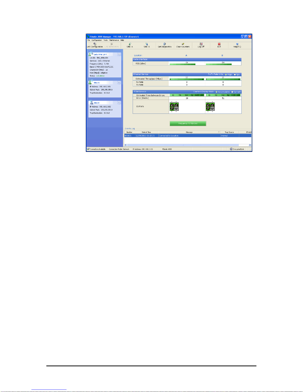
Accessories Chapter 1
FA4800 User Manual Release 1.9.30 1-15
Figure 1-24: FibeAir2000 Manager window
Accessories
Ceragon provides a variety of accessories to support the FA4800 system:
•PoE devices
• AC Power Adaptors
• External Lightning Protection Units
• Cables to connect the various system elements
• Grounding cables
Documentation supplied with FA4800
The technical documentation supplied with a FA4800, is located on the
product CD. It includes the following items:
• A Quick Installation Guide for experienced installers (also hardcopy)
• A full User Manual - the document which you are reading
• A Help file accessible from the FibeAir2000 Manager
• Link Budget Calculator
Page 38

How to Use this Manual Chapter 1
FA4800 User Manual Release 1.9.30 1-16
How to Use this Manual
This User Manual is divided into three functionally distinct sections reflecting
the activities required to set up a FA4800. The division is shown in the following table:
The Basic Installation section is divided into functionally distinct chapters
reflecting the activities required to set up a FA4800. The division is shown in
the following table:
A Little Terminology
In the field, a link typically has a local or headquarters site as for example in
Figure 1-1 above. Here the service provider is the local or headquarters
site. The service recipient is the remote site.
Where the link is completely internal to a corporation, the choice of the local
and remote is just a matter of convenience.
A
link
then, consists of two
sites
.
In Broadband Wireless terminology, the local and remote sites are sometimes referred to as “near” and “far”, “HQ” and “remote” and so on.
Table 1-3: User Manual - General layout
Section General Content Purpose
1
Basic Installation Core information to install and operate a link
2
Advanced Installation Specialized installation techniques
3
Technical Information Back groun d for advanced use
Table 1-4: User Manual layout
Chapter/
Appendix
Subject Audience
2
Site Preparation Site survey team
3
Hardware Installation Field technician
4
Getting Started with the
FibeAir2000 Manager
Installation technician
5
Installing the Link Installation technician
6
The FibeAir2000 Manager: Main Window
Installation technician, System manager
7
Configuring the Link Installation technician, System manager
8
Site Configuration Installation technician, System manager
9
Monitoring and Diagnostics
Installation technician, System manager
Page 39

A Little Terminology Chapter 1
FA4800 User Manual Release 1.9.30 1-17
The site which is closer to the network core (often the local site) will be
referred to as
site A
, and the opposite side of the link, usually closer to the
end user, as
site B
.
This choice is application-neutral and will be used throughout the manual
both to describe the sites and their names as in the examples.
The link is configured and managed using a PC, the
managing computer
connected to site A. (The precise requirements for the managing computer
are set out on page 4-1).
We will occasionally need to distinguish between the site to which the managing computer is connected, and the second site, when they are not necessarily A or B. The former will be called the
managing site
and the latter,
the
over-the-air site
. Which is which, is always determined by the loca-
tion of the managing computer.
FA4800 supports three connection methods for the managing computer:
•
Local
- a direct peer to peer connection between the Ethernet ports
on the managing computer and the IDU or PoE device. Local connection is always read-write.
•
Network
- the managing computer and the site A IDU or PoE
device belong to a LAN and communicate through a router or switch
•
Over-the-air
- the managing computer connects to site B via the
air interface
• The managing computer may be connected to the link through an
IDU or a PoE device. In what follows, where ever we refer to an IDU
it includes PoE devices unless stated otherwise. Typically, if we need
to refer to an IDU as such, we will use a model name such as IDU-C.
The terms uplink and downlink, originate from the field of Satellite communications. In a backhaul or ISP context, uplink is from the user to the
network and downlink is from the network to the user.
Page 40

Conventions Used in this Manual Chapter 1
FA4800 User Manual Release 1.9.30 1-18
Conventions Used in this Manual
Notifications
Notifications consist of Notes, Cautions and Warnings.
Typographical conventions
General
Where a term is defined or introduced for the first time, it is shown in Boldface. You will have noticed this usage in the Terminology section above.
Software
The FibeAir2000 Manager is a Microsoft Windows application following the
user interface conventions of familiar Microsoft Windows programs.
We would describe the chain of menu commands indicated in the navigation
example of Figure 1-25 like this,
Tools|Active Alarms|1 A
using Boldface for the menu labels and vertical bars to separate them.
Note
The purpose of a Note is to
• Draw your attention to something that may not be obvious or counter-intuitive
• Emphasize a special feature or peculiarity of the FA4800
• Offer an external reference for additional information
• Add a caveat that would not qualify as a full Caution or Warning (see
below)
• Provide additional background to what follows
• Offer a recommendation
• Highlight an indication of something to watch out for
• Advise you if an action has “side effects” i.e. it may disturb something
else that would be best left undisturbed
• Remind you of something that should be kept in mind
Caution
A Caution is a notification of risk of damage to equipment or of service
degradation
Warning
A Warning is a notification of risk of danger to persons operating near the
equipment
Page 41
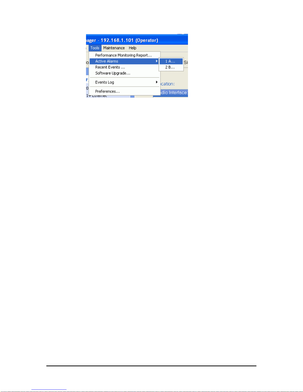
Windows Terminology Chapter 1
FA4800 User Manual Release 1.9.30 1-19
Figure 1-25: Menu navigation in the FibeAir2000 Manager
Similarly, mouse click items will be referred to like this:
“Click Next to continue.”
(A mouse click always uses the left mouse button unless stated otherwise.)
Windows Terminology
Look at Figure 1-1 above. The main application display which you see consists of a frame-window with a menu bar, system icons and content. It will
be referred to as a window, the main window or the Manager window
depending on context.
The top line of icons is the tool bar, and provides part of the menu bar
functionality with a mouse click.
At the bottom of the window is the status bar, a line of icons and text
boxes.
The central part of the main window consists of several panes: On the
right, there are Radio Interference, Ethernet Service and the Frequency
panes. The left hand pane (with the blue background) is split into three
sub-panes.
If you click Site A or Site B in the tool bar, you will be offered another window, which in turn displays on of several panels depending on which function you choose.
Page 42
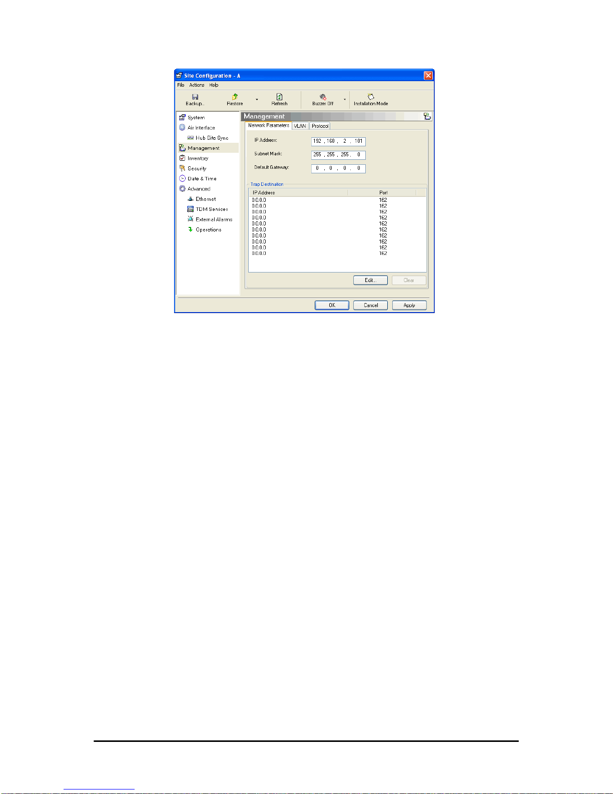
Viewing and Printing Chapter 1
FA4800 User Manual Release 1.9.30 1-20
Figure 1-26: Site Configuration window with open Management panel
Viewing and Printing
This manual is optimized for viewing online as a PDF file. To this end it uses
an 11 point Tahoma typeface for main text. Tables for most part, use 7 or 8
point fonts. Here are a few pointers for hard-copy printing:
• The text and table typefaces used are large enough to print the
manual at two pages per sheet
• For good legibility, use a commercial grade laser printer. A color
printer is of course best, however a monochrome printer set to use
gray-scale gives acceptable results
• Better quality inkjet printers also give good output
Page 43

FA4800 User Manual Release 1.9.30 2-1
Chapter 2
Site Preparation
Planning the Link Site
Overview
Link site planning consists of a set of surveys, which must be carried out
before any equipment is brought to the site. If for some reason, the outcome of any of these surveys is negative, site re-location will need to be
considered.
A Site Survey consists of three stages:
1. Preliminary survey - The proposed link is analyzed in the office using a
topographic map.
2. Physical survey - The locations of the indoor and outdoor equipment are
determined on-site.
3. Radio Frequency (RF) survey - It is recommended that the installation
area be scanned with a spectrum analyzer, to identify RF interference so
as to determine a clear channel for radio installation (on-site).
The Site Survey
Introduction
Ceragon wireless links must be planned before installation. The designated
installation site must be appraised to determine that the wireless system is
able to operate efficiently and provide connectivity without signal degradation.
FA4800 offers a wide operating frequency range. A free frequency channel
must be determined within the operating range, for optimum performance.
Recommended Equipment
Stage 1: Preliminary Survey
• Topological map of the area
• Urban map of the area
Page 44

Stage 1: Preliminary Survey Chapter 2
FA4800 User Manual Release 1.9.30 2-2
•Compass
Stage 2: Physical Survey
• 100 meter tape measure
• Ohmmeter, to check ground connection
•Binoculars
•Map
• Digital camera
• Paper, pencil, and a clipboard
• GPS device (optional)
• Compass (optional)
Stage 3: RF Survey
• Spectrum Analyzer with Max Hold function and screen capture facility that can store multiple images, for documentation purposes
• RF accessories (connectors and cables)
• Communication devices (for example, cellular phones, or a set of
walkie-talkies)
Stage 1: Preliminary Survey
A preliminary survey is necessary before visiting potential installation sites.
As much detail as possible should be obtained about the two designated
ODU installation sites and the area between them.
¾ To perform a preliminary survey:
1. Mark the two designated installation sites on a topographic map of the
area.
2. Measure the distance between the sites; check that it is within the specified range of the equipment.
3. On the urban map, check for developed areas situated between the two
installation sites. Pay attention to these areas when performing the physical site survey; there may be tall buildings, RF towers, or transmitters,
which could cause interference to the link.
4. Check the area between the two sites for obstructions such as:
• High ground - hills or mountains
• Lakes or large bodies of water. Water has a reflection effect on RF
signals like a building. This type of reflection causes the received
amplitude to be reduced. As a rule of thumb, the presence of a large
body of water between the link sites may double the required
antenna height.
5. Determine and record the compass bearings between both ODUs, relative to north.
6. If there are obstructions between the two sites, calculate the Fresnel
Zone (see 21 for details).
7. If the site chosen does not meet requirements, consider alternative sites.
Page 45

Stage 2: Physical Survey Chapter 2
FA4800 User Manual Release 1.9.30 2-3
8. Use the Link Budget Calculator (on the CD supplied with the equipment
or using the FibeAir2000 Manager) to determine the expected performance.
Stage 2: Physical Survey
The physical site survey reviews the environment of the proposed installation location, to ensure that the link sites are suitable for the wireless network. The results of the physical site survey should be recorded.
¾ To perform a physical survey:
1. From the compass readings taken in the preliminary survey, find the azimuth (horizontal position) that the ODU should face towards the second
ODU.
2. Using binoculars, locate any obstructions such as tall trees, high buildings, hills or mountains. Look for other RF towers between the two sites.
Mark the locations of the obstructions on the map.
3. Determine the location for the ODU (having regard for existing rooftop
installations and tower space). It should be above any obstructions, considering the Fresnel zone (see 21).
4. If you need to install the ODU on a tower, make sure that the tower is far
away from overhead electric power lines.
5. Determine a location for the indoor equipment; it should be as close as
possible to the ODU. At an existing site, there is probably an equipment
room with cable-routing channels.
6. Measure and record the path length of the cable from the ODU position
to the indoor equipment room.
7 . Determine the ground and lightning connection points of the installation.
The ODU and IDU must both be grounded.
8. Using the Ohmmeter, measure and record the resistance of the required
installation to the grounding point. The resistance must be less than 1O
ohm.
9. Review the results of the physical site survey . Decide if the site is suitable
for the wireless network installation.
• If the site is suitable, continue with stage 3, the RF survey
• If the site is not suitable, survey another site
Note
It is advisable to go on a clear day, so y ou can more easily see any
obstructions between the two sites.
Note
The IDU - ODU cable length limit is 100m, in accordance with IEEE 10/
100BaseT standards.
Page 46

Additional Outdoor Site Requirements Chapter 2
FA4800 User Manual Release 1.9.30 2-4
Additional Outdoor Site Requirements
The ambient outdoor operating temperature should be -35 to 60°C (-31 to
140°F).
Additional Indoor Site Requirements
The following requirements guarantee proper operation of the system:
• For IDU-C units, allow at least 90 cm (36 “) of front clearance for
operating and maintenance accessibility. Allow at least 10 cm (4 “)
clearance at the rear of the unit for signal lines and interface cables
• The ambient operating temperature should be 0 to 50°C (32 to 122
°F) at a humidity of up to 90%, non condensing
Stage 3: RF Survey
The RF survey examines the wireless environment of the installation site, to
determine whether there are available channels within the radio operating
frequency band. An RF survey is performed using a spectrum analyzer.
It is advisable to familiarize yourself with the spectrum analyzer before
going out on site, specifically the Max Hold and Marker functions.
You should perform the RF survey at both proposed link sites.
The survey should be carried out during a busy time of day, to best judge
the worst-case radio interference. Allow 2-4 hours duration for a good RF
survey.
RF Planning for Dense Installations and Collocated Sites
Interference may arise from
• Self interference from collocated Ceragon radios
• Other collocated radio devices installed on the same site.
To avoid or minimize interference, follow these recommendations:
• For collocated Ceragon units, use an HSS unit to synchronize
between them. Select a different operating channels for each collocated Ceragon unit.
• If one or more collocated units are not Ceragon units, ensure that
there is a physical separation of at least three meters between a
Ceragon unit and any other collocated radio on the site.
• Use the largest possible frequency gap between these units.
Note
It is possible to install the link and use the FibeAir2000 Manager to find a
clear channel. Each frequency channel can be evaluated in turn.
Achievement of a clear channel is indicated by the marker in the Quality bar
on the Channel Setting window (see Figure 5-6) moving into the green
area.
Page 47

RF Planning for Dense Installations and Collocated Sites Chapter 2
FA4800 User Manual Release 1.9.30 2-5
• Choose the best frequency channel (as clear as possible form interference). Y ou may change band with “Combo” FA4800 products and
all FibeAir 2000 products).
• To select a frequency channel, move the link to Installation Mode
(using Site configuration) and start the Installation wizard. In the
Channel Settings window, use the quality bar at the bottom to
help you choose a better channel (clearer of interference).
• If you are using F A4800 radios, install the collocated links with different antenna polarizations.
• If you are using the FibeAir 2000 radios, use the Spectrum View
tool to find the best working channel (Tools | Spectrum View).
• Decreasing the Tx Power of a link will reduce collocation interference
(Site Configuration | Air Interface).
Note
Use the Link Budget Calculator to determine the minimum Tx Power
required to maintain link stability.
Page 48

FA4800 User Manual Release 1.9.30 3-1
Chapter 3
Hardware Installation
This chapter sets out the requirements and procedures for the hardware
installation and alignment of a FA4800 link in accordance with the prior
planning as set out in Chapter 2. It is intended to guide qualified field
technicians.
Safety Practices
Preventing overexposure to RF energy
To protect against overexposure to RF energy, install the ODUs so as to provide and maintain minimal separation distances from all persons.
When the system is operational, avoid standing directly in front of the
antenna. Strong RF fields are present when the transmitter is on. The ODU
must not be deployed in a location where it is possible for people to stand
or walk inadvertently in front of the antenna.
Grounding
All Ceragon products should be grounded during operation. In addition:
•The ODU should be earthed by a wire with diameter of at least
12AWG.
The FA4800 ODU must be properly grounded to protect against
lightning. It is the user's responsibility to install the equipment in
Warning
Outdoor units and antennas should be installed ONLY by experienced
installation professionals who are familiar with local building and safety
codes and, wherever applicable, are licensed by the appropriate
government regulatory authorities. Failure to do so may expose the end
user or the service provider to legal and financial liabilities. Ceragon and its
resellers or distributors are not liable for injury, damage or violation of
regulations associated with the installation of outdoor units or antennas.
Note
The material in this chapter is generic to all Ceragon radio link products
unless stated otherwise.
Page 49

Protection against Lightning Chapter 3
FA4800 User Manual Release 1.9.30 3-2
accordance with Section 810 of the National Electric Code, ANSI/
NFPA No.70-1984 or Section 54 of the Canadian Electrical Code.
These codes describe correct installation procedures for grounding
the outdoor unit, mast, lead-in wire and discharge unit. It also lays
down the size of grounding conductors and connection requirements
for grounding electrodes.
The FA4800 ODU must be grounded to a Protective Earth as
described in Chapter 18 and in accordance with the Local Electrical
Regulations.
• The earth lug on the IDU-C should be connected to the protective
earth at all times, by a wire with a diameter of 18 AWG or wider.
Rack-mounted equipment should be mounted only in earthed racks
and cabinets.
Further, you should -
• Always make the ground connection first and disconnect it last
• Never connect telecommunication cables to ungrounded equipment
• Ensure that all other cables are disconnected before disconnecting
the ground
More detailed guidelines are supplied in Chapter 18.
Protection against Lightning
The use of lightning protection is dependent on regulatory and end user
requirements. All of Ceragon outdoor units are designed with surge limiting
circuits to minimize the risk of damage due to lightning strikes. Ceragon recommends the use of additional surge arrestor devices to protect the equipment from nearby lightning strikes.
See Chapter 18 for detailed installation instructions of lightning protection
devices.
General
• It is recommended that installation of the outdoor unit be contracted
to a professional installer.
• Before working on equipment connected to power lines or telecommunication lines, you should remove jewelry or any other metallic
object that may come into contact with energized parts.
• Use extreme care when installing antennas near power lines.
• Use extreme care when working at heights.
• When using an AC power source for FA4800 always use the AC
power adapter supplied by Ceragon.
• Use the right tools. In addition to standard tools required for any
kind of ODU or antenna installation, FA4800 requires additional specific tools detailed on page 3-6 below.
Page 50

Package Contents Chapter 3
FA4800 User Manual Release 1.9.30 3-3
Package Contents
The FA4800 packages include the following items:
ODU Package Contents
The ODU package contains:
•One ODU - see Figure 3-2 and Figure 3-3 below for front and rear
view
• An ODU mounting kit - see Figure 3-1 below
• A CD containing -
• the FibeAir2000 Manager
•Quick Start Guide
• User Manual - the document you are reading
• Link Budget Calculator
• Label showing the MAC address and the alternative Community
string. The label is self-adhesive. You should keep this label safe
• Cable glands (to be used with the ODU-IDU cable)
Figure 3-1: ODU Mounting kit
Figure 3-2: Connectorized ODU - Front and rear views
ODU - Front View ODU - Rear View
Page 51
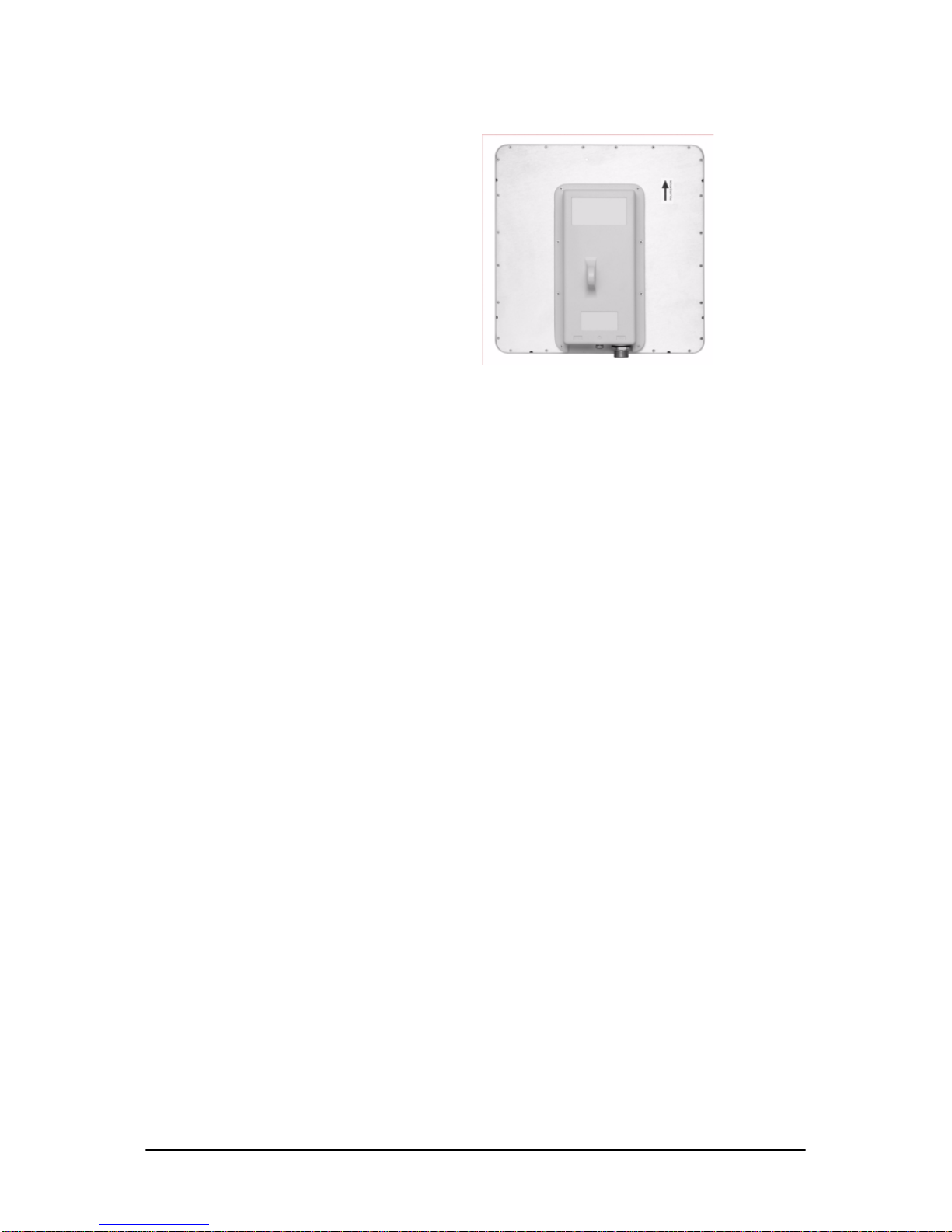
IDU-E or IDU-R package containing: Chapter 3
FA4800 User Manual Release 1.9.30 3-4
Figure 3-3: Integrated ODU - Front and rear views
IDU-E or IDU-R package containing:
• IDU-E or IDU-R
• AC/DC Converter
• IDU-E wall-mounting drilling template
• Self adhesive label showing the IDU LED operation
Figure 3-4: IDU-E/R - front view
IDU-C Package Contents
The IDU-c package contains:
• IDU-C - see Figure 3-5 below.
• 19” rack mounting kit - see Figure 3-7 below
• Two DC power plugs for power cables - see Figure 3-7 below
Figure 3-5: IDU-C Package contents - the IDU-C, Ethernet only
ODU - Front View ODU - Rear View
Page 52

PoE-8 Package Containing: Chapter 3
FA4800 User Manual Release 1.9.30 3-5
Figure 3-6: IDU-C Package contents - the IDU-C, 4 E1/T1 ports
1
Figure 3-7: IDU-C Package contents - the mounting kit and DC power plugs
PoE-8 Package Containing:
Figure 3-8: PoE-8 Unit
•PoE-8
• 110/240 VAC with IEC 60320 socket cable
• 3-prong terminal block connector (green)
• 19" mounting kit
External Antenna Package Contents
•Antenna
• RF cable 1m (3’) long; two cables supplied with bipolar antennas,
single cable supplied with monopolar antennas
• Mounting kit
1. The IDU-C is available with 0, 4, 8 or 16 TDM ports. FA4800 supports 0 or 4 TDM ports.
Page 53

Additional Tools and Materials Required Chapter 3
FA4800 User Manual Release 1.9.30 3-6
Additional Tools and Materials Required
The following is a list of the equipment and materials required to install
FA4800 hardware.
Tools and Materials
• Crimping tool for RJ-45 (if the ODU-IDU cable is without connectors)
• Spanner/wrench 13 mm (½”)
• Drill (for wall mounting only)
•Cable ties
• Sealing material
Cables and connectors
• ODU grounding cable 12AWG
• IDU grounding cable 18AWG
• ODU-IDU cable (outdoor class, CAT-5e, 4 twisted pairs, 24AWG)
• For PoE based links: A crossed Ethernet LAN cable
• O-PoE 10AWG grounding cable if applicable
• BDU grounding cable 18AWG if applicable
Hardware Installation Sequence
The following steps are required to install the FA4800 system:
1. Mounting the ODUs, page page 3-7.
2. Mounting the external antennas (if used), page page 3-8.
3. Mounting the Lightning Protection devices (if used), page page 3-8.
4. Outdoor connections, page page 3-9.
5. Mounting the IDUs, page page 3-10.
6. Indoor connections, page page 3-13.
7. Aligning the ODUs/antennas, page page 3-14.
See Figure 3-9 below, which illustrates a typical installation of a FibeAir
2000 or a FA4800 with external antenna(s).
Page 54

Outdoor installation Chapter 3
FA4800 User Manual Release 1.9.30 3-7
Figure 3-9: Typical Installation (with external antenna) Left: FibeAir 2000 Right: FA4800
The installation steps are detailed in the following sections.
Outdoor installation
Preparing the ODU before Deployment
Each ODU must be pre-loaded with an IP address. This may be done prior
to deployment in the field, or on-site using a Laptop computer. The process
is quite straight-forward and described in Chapter 19.
Mounting the ODU
The ODU can be mounted on a pole or a wall. In both installations, the supplied mounting kit is used to secure the ODU.
A FA4800 link operates in pairs of two ODUs with the same configuration.
Both ODUs must be installed, and the antennas aligned for maximum
throughput.
Note
A mast-sited ODU typically uses a pole attached to the mast.
Page 55

Mounting external antennas Chapter 3
FA4800 User Manual Release 1.9.30 3-8
¾ To mount the ODU on a pole or a wall:
1. Ensure that the ODU is properly grounded.
2. Mount the ODU onto the pole or wall. Ensure that the unit is oriented so
that the cable connectors are at the bottom. (If they are on top,
water may penetrate into the unit causing damage.) It is possible
to mount an ODU horizontally. See Chapter 17 for details.
3. Refer also to Chapter 17 for detailed ODU mounting kit contents and
schematics.
Mounting external antennas
If you are using ODU with an integrated antenna, skip to Mounting the
Lightning Protection Devices below.
The supplied mounting kit is used to mount the antenna onto a pole. The
antennas must be aligned for maximum throughput.
¾ To mount an external antenna:
1. To mount an external antenna, ensure that the antenna is properly
grounded and then mount the antenna onto the pole. Refer to Chapter
17 for detailed antenna mounting instructions.
2. Follow the mounting instructions supplied with the antenna.
Mounting the Lightning Protection Devices
The use of lightning protection is dependent on regulatory and end user
requirements. The FA4800 ODU is designed with surge limiting circuits to
minimize the risk of damage due to lightning strikes. Ceragon recommends
the use of additional surge arrestor devices to protect the equipment from
nearby lightning strikes.
Warning
Prior to connecting cables to the ODU, the protective earth terminal (screw)
of the ODU must be connected to an external protective ground conductor
or to a grounded pole.
• Only a qualified person using the proper safety equipment should
climb the antenna mast
• Only qualified professional personnel should install or dismantle
ODUs and masts
Note
• Do not tighten the ODU to its mounting brackets until the alignment
process of the antenna is complete.
• Ensure that there are no direct obstructions in front of the ODU or
interference from man-made obstacles.
Warning
Do not stand in front of a live antenna.
Page 56

Outdoor Connections Chapter 3
FA4800 User Manual Release 1.9.30 3-9
Refer to Chapter 18 for detailed installation instructions of lightning protection devices.
Outdoor Connections
¾ To complete the outdoor connections:
1. Connect the ground cable to the ODU chassis as marked on the ODU.
2. Connect the antenna cable to the ODU.
3. Connect the lightning protection device to the ODU (see Chapter 18).
4. Attach the ODU-IDU cable to the ODU RJ-45 connector (see Appendix B
for the connector pinout)
5. Screw in the cable glands to ensure hermetic sealing of the ODU.
6. Secure the cables to the pole, mast or brackets using UV-rated cable ties.
Indoor Installation
Installing IDU-E and R units
IDU-E Installation
The IDU-E can be wall mounted, placed on a desktop or take up one half of
a 1U rack slot. The unit should be grounded, cabled to the ODU and connected to power using the supplied AC/DC adapter.
.
Figure 3-10: New style IDU-E: Rear panel
IDU-R Installation
Figure 3-11: IDU-R Rear Panel
Installation of an IDU-R unit differs from other IDU models in one respect:
At the rear of the IDU-R (see Figure 3-11) there are two jacks labeled
“Trunks” . F or each IDU-R, the E1 cable from outside should be plugged into
one of the trunks, and the E1 cable to the other station should be plugged
into the second trunk, as in the left hand side of Figure 1-13.
Apart from the above difference, the link installation including the remaining
part of the IDU installation and connection to the ODU proceeds as
described as above.
Page 57
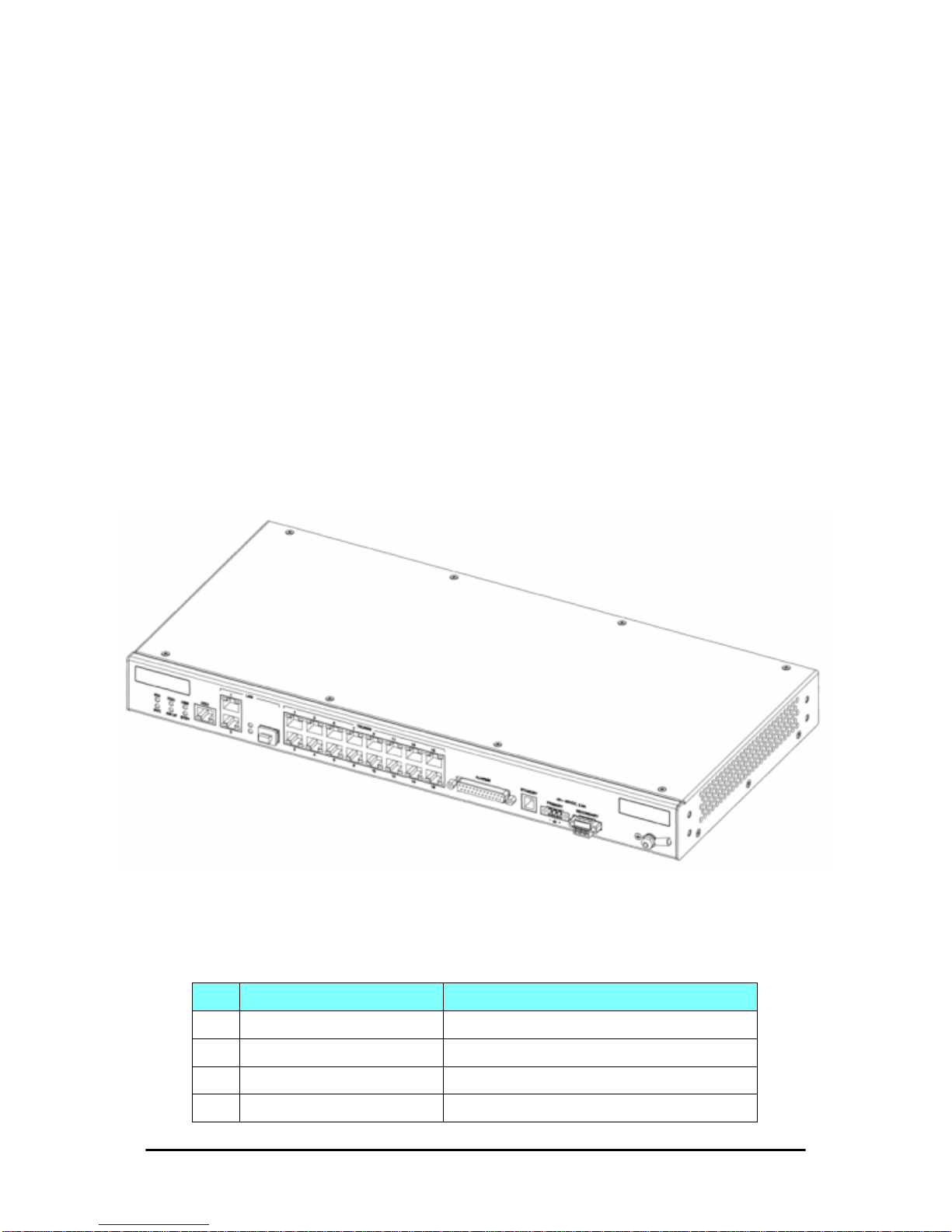
Mounting the IDU-C Chapter 3
FA4800 User Manual Release 1.9.30 3-10
Mounting the IDU-C
The FA4800 IDU- As are all rack mountable, as shown in Figure 3-12. A
front panel keyed schematic of a rack mounted IDU-C is shown in the figure
below.
Figure 3-12: IDU-C front panel
In Figure 3-13 we display a perspective view of the IDU-C:
Figure 3-13: IDU-C - A perspective view
Further description of the keyed items in Figure 3-12 is shown in Table 3-
1 below:
Table 3-1: Components of an IDU-C front panel
Key Label Remarks
A Indicator LEDs S e e Figure 3-14.
B ODU Port RJ-45 connector, see Table B-1.
C LAN RJ45Ports Ethernet, RJ-45 connector, see Table B-3.
D LAN SFP Port See Appendix C.
Page 58
Mounting the IDU-C Chapter 3
FA4800 User Manual Release 1.9.30 3-11
The Indicator LEDs (Item A in Table 3-1 above) are shown in more detail
below:
Figure 3-14: IDU-C Front Panel LEDs
Figure 3-15: IDU-E Front Panel LEDs
The purpose of the LEDs is shown in Table 3-2 below:
E Alarm Ports Standard DB25 female connector, see Table B-7.
F Label indent Place for adhesive identification labels.
G Primary 3 pin Power Connector
Standard 3 pins in line power connector, see Table B-8.
H Secondary 3 pin Power Connector
I Grounding Lug Use the lug supplied.
J Rack mounting holes
K Detachable Rack mounting brackets
L 0, 4, 8 or 16 E1/ T 1 Ports See Table B-5.
M Standby Port Hot Standby ready: HSB cable socket, see Table B-6.
Table 3-2: IDU-C and IDU-E/R Front Panel LEDs
Name Color Function
IDU
Green
Blinking Green
Red
Blinking Orange
IDU operational
During power-up only
Failure
During power-up; continues if ODU fails to load IDU firmware.
Also, when using an IDU-C to replace a PoE device in which case all other LEDs off.
ODU
Green
Red
ODU-to-IDU communication link is operating
ODU-to-IDU communication link is disrupted
Table 3-1: Components of an IDU-C front panel
Key Label Remarks
Page 59

Mounting the IDU-C Chapter 3
FA4800 User Manual Release 1.9.30 3-12
¾ To mount an IDU-C:
1. Attach the rack mounting brackets (K) to the IDU.
2. Bolt the IDU into an empty slot in the rack, ensuring that it sits securely.
3. Ground the IDU to the rack using grounding lug I. The IDU should be left
permanently grounded.
AIR I/F
Green
Orange
Red
Wireless link is synchronized
During installation mode; also signals software mismatch on some identical ODUs
Wireless link lost synchronization
SVC
Green
Orange
Blinking Orange
Red
Off
E1 or T1 line is synchronized
Alarm detected at the opposite site interface; Normal or LOSS
Local or remote loopback
Alarm detected at this site interface
Ethernet only IDU or E1/T1 not configured
HSS S ee supplementary Table 3-3 following.
STBY
Hot Standby Mode Link State
Green
Blinking Green
Red
Orange
Off
Primary
Secondary
Primary
Secondary
Off
Active
Not active
Not active
Active
HSM not activated
Table 3-3: IDU-C and New Style IDU-E Front Panel LEDs for HSS
Color Function
Green This ODU is HSS master, generating signal, and HSS Sync is OK
Blinking
Green
This ODU is a HSS client and in Sync
Red HSS not operational due to improper signal detection. This ODU is not transmitting
Orange
HSS is operational. One of the following conditions apply:
• This ODU is a master that is generating signals and detecting signals
• This ODU is a master that is generating signals but detected improper signals
• This ODU is a client “Continue Tx” but is not detecting signals
• This ODU is a client “Disable Tx” and is detecting signals from multiple sources
All orange cases transmit.
Off
HSS is not activated
HSS is not supported
Disconnection between ODU and IDU
Note
Instead of using the rack mounting brackets, the IDU may be rail mounted
using the four screw holes on each of its sides.
Table 3-2: IDU-C and IDU-E/R Front Panel LEDs (Continued)
Name Color Function
Page 60

Connecting power to the IDU Chapter 3
FA4800 User Manual Release 1.9.30 3-13
Connecting power to the IDU
The IDU-C has redundant power connection circuits (items G and H in
Figure 3-12 above). An enlarged schematic of the power connectors is
shown in below:
Figure 3-16: IDU-C Power connectors
The connectors are 3 pin in line female, with polarities (left to right) minus,
ground, plus. To avoid damage to the IDU, always use an AC/DC adapter
supplied by Ceragon.
Ensure that the IDUs at both sites are powered up.
The IDU-E has a single three pin power connector, the same as used on the
IDU-C.
The IDU-R models have a two pin power connector and an AC/DC adapter
supplied by Ceragon.
Connecting the ODU to the IDU
The ODU-IDU cable conducts all the user traffic between the IDU and the
ODU, and also provides power to the ODU. The maximum length of the
ODU-IDU cable is 100m (328ft) in accordance with 10/100BaseT standards.
The ODU-IDU cable is supplied pre-assembled with RJ-45 connectors, at the
length specified when ordering, or as a cable drum with spare connectors. If
the ODU-IDU cable was not ordered, use an outdoor class, CAT-5e 24AWG
shielded cable. See Appendix B for Wiring Specifications.
To connect the ODU to the IDU, route the cable from the ODU to the IDU,
secure the cable along its path and connect the cable to the ODU RJ-45
connector on the IDU (see item B in Figure 3-12 above).
Installing a Link using PoE Devices
The PoE device is a very simple unit having a power input connector and
two Ethernet ports. It is AC powered, and has a power LED.
¾ To prepare a link using PoE devices:
1. To connect the ODU to the PoE device, route the cable from the ODU to
the PoE device, secure the cable along its path and connect the cable to
the LAN-OUT RJ-45 connector on the PoE device.
2. Connect it to AC power.
Page 61

Connecting User Equipment Chapter 3
FA4800 User Manual Release 1.9.30 3-14
3. Repeat steps 1 to 2 for the second link.
4. If you are us ing a BDU, you should refer t o the Cer agon Base Di stribution
Unit User Manual.
Connecting User Equipment
¾ To connect user equipment to an IDU:
1. Connect user switch/router or any other compatible device to the IDU
panel RJ-45 ports designated LAN. (For an IDU-C, see item C in
Figure 3-12 above.)
2. Connect user E1/T1 traffic to the IDU panel RJ-45 ports designated
TRUNKS. (For an IDU-C, see labeled item L in Figure 3-12 above.)
3. IDU-C only: To use the SFP Port (labeled item D in Figure 3-12 above),
insert an SFP plug-in module into the port and connect the user switch/
router or any other compatible device to the SFP plug-in module.
Refer to Appendix B for connector pinouts.
¾ To connect user equipment to a PoE device:
• Connect a user switch, router or any other compatible device to the PoE
device RJ-45 port designated LAN-IN. Refer to Appendix B for connector pinouts.
Connecting and Aligning ODUs / Antennas
You perform antenna alignment using the ODU's audi ble tone.
The method is not suitable for the following models:
To speed up the installation time, alignment of a FA4800 system should be
performed by two teams simultaneously, at site A and at site B.
¾ To align the ODUs using the alignment tone:
1. Verify that power is connected to the IDUs at both sites.
Note
Do not connect two LAN ports to the same network, or flooding may occur.
Model See Reference
BRS Chapter 23
FCC/IC 5.4 / 5.3 GHz Chapter 16
AIND Chapter 22
Warning
When aligning the antennas, do not stand in front of a live antenna.
Page 62
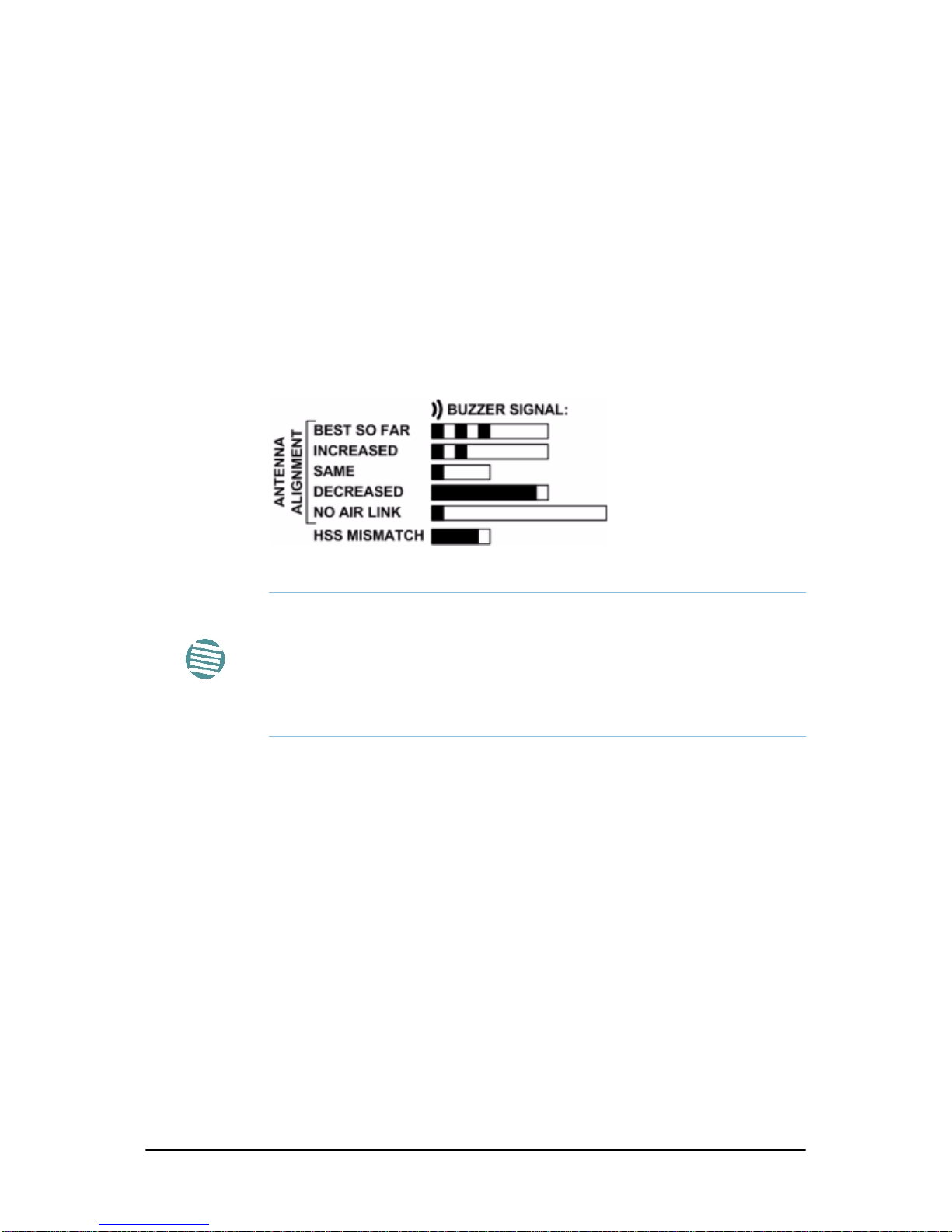
Connecting and Aligning ODUs / Antennas Chapter 3
FA4800 User Manual Release 1.9.30 3-15
Provided that Site A detects the signal from Site B, the ODU starts beeping 20 seconds after power up, and continues beeping until the ODUs are
aligned, and the installation is complete.
2. Verify normal operation of the IDU by the LED indications on the front
panel (see Table 3-2).
3. Direct the antenna of site B in the direction of the site A. This is simplified
if a previous site survey has been completed and azimuths are known.
4. Make an azimuth sweep of 180 degrees with the site A ODU so that the
strongest signal from site B can be detected.
5. Slowly turning the site A ODU back towards the position of Site B, listen
to the tone until the best signal is reached. See the following figure for
audible signal variations.
Figure 3-17: Beep Sequence for antenna alignment
6. Secure the site A ODU to the mast/wall.
7. At site B, adjust the ODU slowly whilst listening to the beeper sequence
until the best signal is attained.
8. Secure the site B ODU to the mast/wall.
9. Monitor the link quality for about 15 minutes to verify stability
Note
• Three beeps and a pause is 'best signal so far'
• Two beeps and a pause is 'signal quality increased'
• One beep and pause is 'no change in signal'
• Long beep and short pause is 'signal quality decreased'
• One beep and a long pause is 'no air link'
• Any other signal does not relate to antenna alignment
Page 63

FA4800 User Manual Release 1.9.30 4-1
Chapter 4
Getting Started with the
FibeAir2000 Manager
Installing the FibeAir2000 Manager Application
Minimum System Requirements
The FibeAir2000 Manager application is distributed on a CD. Operating system specific PC resources required by the application are set out in
Table 4-1 below:
Requirements common to all systems are:
• Hard disk: 1 GB free space
• Network: 10/100BaseT NIC
• Graphics: 1024x768 screen resolution with 16 bit color
• Microsoft Explorer version 5.01 or later
Installing the Software
Any PC running the FibeAir2000 Manager application can be used to configure a FA4800 link.
¾ To install the FibeAir2000 Manager program:
1. Insert the CD-ROM into your CD-ROM drive.
The installation starts automatically.
Table 4-1: PC Requirements for the FibeAir2000 Manager Application
Windows Version
2000 XP Pro Vista/7
Memory 128 MB 512 MB 1 GB
Processor P III P IV P IV Dual Core
Page 64

Getting Started with the FibeAir2000 Manager Chapter 4
FA4800 User Manual Release 1.9.30 4-2
2. Follow the on-screen instructions of the installation wizard to complete
setup of the FibeAir2000 Manager program in the desired location.
Getting Started with the FibeAir2000 Manager
If your links are within easy reach, you can configure them using the procedure described below. If however, your links are to be geographically scattered, it may be convenient to pre-load each ODU with its network address
prior to physical installation. The procedure is quite straight forward, and
set out in 19.
¾ To start the FibeAir2000 Manager:
1. Connect the managing computer to one of the two LAN ports as shown in
Figure 4-1 below:
Figure 4-1: LAN ports on the front panel of the IDU-C
If you are not using a direct connection as above, ensure that you have
IDU to managing computer connectivity (e.g. through a LAN).
2. Check that you have connectivity to the ODU. Y o u can do this by opening
up a command line session (Start|Run and then type, cmd). At the
command prompt, type
ping 10.0.0.120
You should see something like this:
Note
Each ODU requires a static IP address, since part of the link definition is the
IP address pair of both ODUs. Network Managers should ensure that these
addresses are outside of the automatic allocation ranges used by their
network DHCP server.
Note
For IDU-E users: The LAN ports are located on the rear panel on the unit.
Page 65
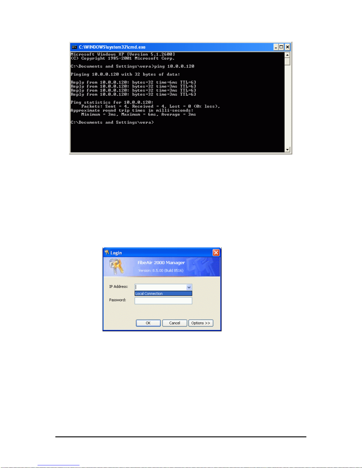
The FibeAir2000 Manager log-on Concept Chapter 4
FA4800 User Manual Release 1.9.30 4-3
Figure 4-2: Pinging an uninstalled and unconfigured link
Any other response from ping means that the ODU is not responding.
Check your Ethernet connection and that both the IDU and ODU are
switched on and then try again. If you do not succeed, seek assistance
from Ceragon Customer Support.
3. Dismiss the command line session.
4. Double-click the FibeAir2000 Manager icon on the desktop, or click
Start|Programs|FibeAir2000 Manager|FibeAir2000 Manager.
The Log-on dialog box appears.
Figure 4-3: First time log-on window
The FibeAir2000 Manager log-on Concept
The FibeAir2000 Manager provides three levels of access in one of two entry
modes. To see them, click Options at any time in the Log on window
(Figure 4-3 above). You are offered an
extended
log-on window:
Page 66
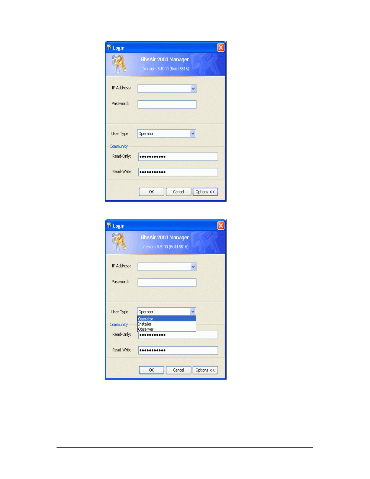
The FibeAir2000 Manager log-on Concept Chapter 4
FA4800 User Manual Release 1.9.30 4-4
Extended log-on window
At the User Type field, click the list button:
Figure 4-4: Log on window exposing the user types.
There are three user types:
•An
Observer
has read-only access to the link. An Observer can
monitor the link, generate reports, but may not change any link
parameters.
•An
Operator
can install and configure the link.
Page 67
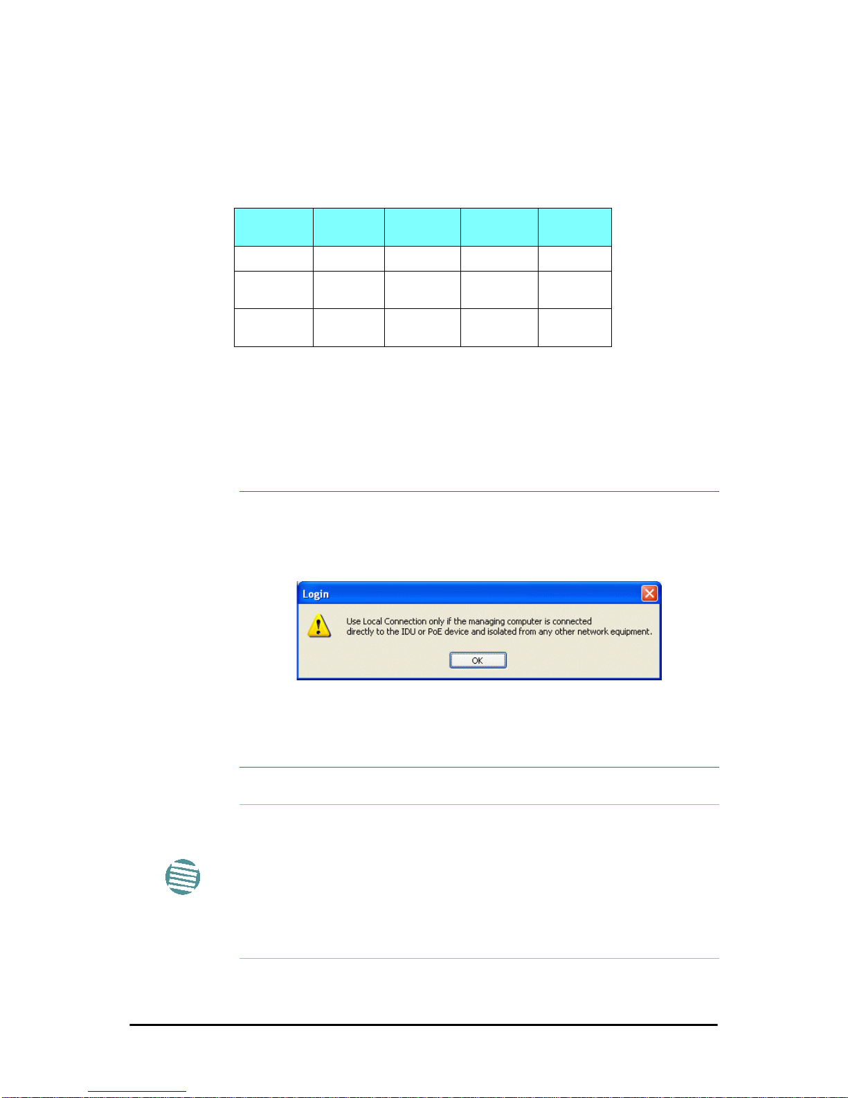
The FibeAir2000 Manager log-on Concept Chapter 4
FA4800 User Manual Release 1.9.30 4-5
•An
Installer
can, in addition to functioning as an Operator, also
change the operating band. The latter function has legal ramifications, requiring familiarity with local regulations.
The following table summarizes these options:
The Network Manager should change the default passwords as soon as possible.
¾ Continuing the log-on procedure:
5. Type an IP address for the ODU (if you connect through a LAN), or click
Local Connection (if you are connected directly to the IDU port).
6. If your User Type is not Operator, then choose it now.
Table 4-2: User types, default passwords and function
User Type
Default
Password
Function Community
Community
String
Observer
admin
Monitoring Read-Only
public
Operator
admin
Installation,
configuration
Read-Write
netman
Installer
wireless
Operator plus
set band
Read-Write
netman
Warning
• If you log on using Local Connection, but your physical connection
is not local (i.e. anything other than a direct connection between the
managing computer and the IDU), then any configuration you carry
out may affect other links in the network. Do not do this!
• Network log on (IP address to the ODU) is recommended.
• If you log on via an over-the-air IP address, you will receive a warn-
ing. If you reset the site to which you are connected to factory settings, you can lock yourself out of the link.
Note
• If you log on using Local Connection through a PoE device, you will
need to connect it to the managing computer using a crossed Ethernet cable.
• The default IP address for the ODU is 10.0.0.120. The subnet mask is
255.0.0.0.
• The actual IP address is defined during link configuration (see Site
Management: IP Address, VLAN and Protoc ol on page 8-7. See
also, 19).
Page 68
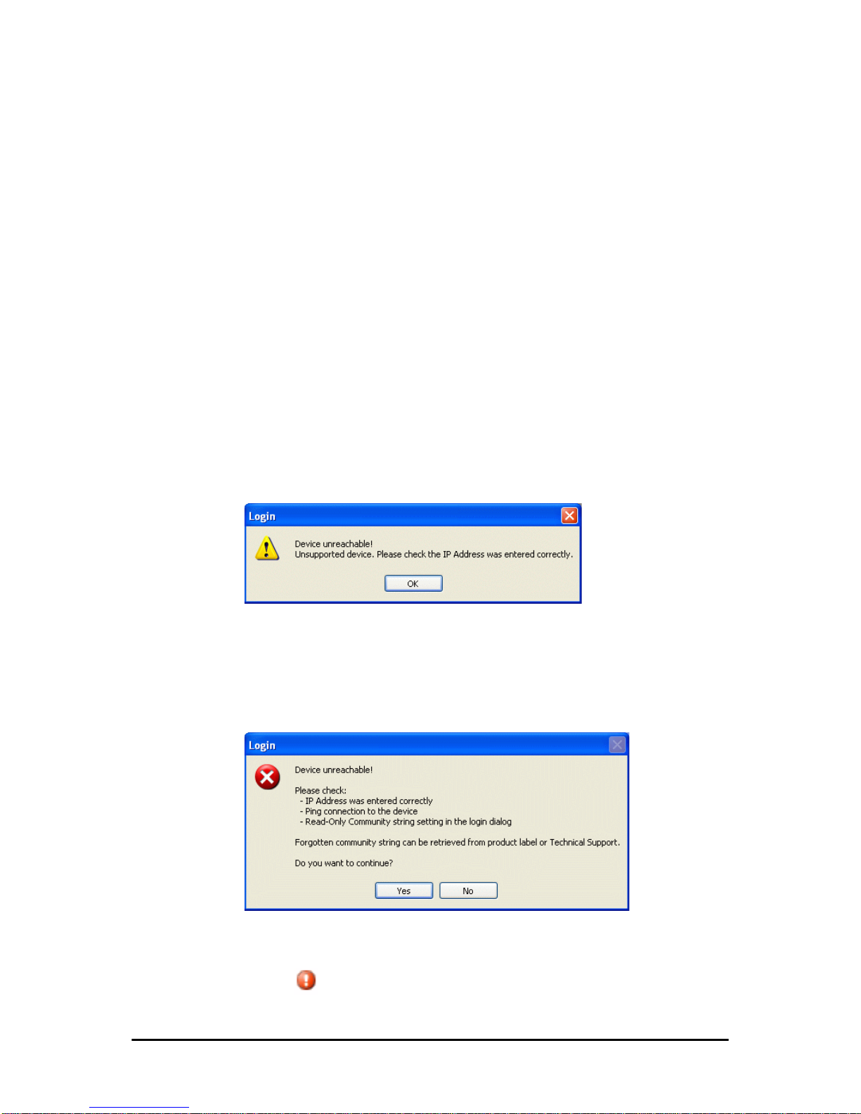
Log-on Errors and Cautions Chapter 4
FA4800 User Manual Release 1.9.30 4-6
7. Enter the password.
8. If you are a user with Read-Write permission, click Options to enter the
Community options if required
9. For initial log on:
• Leave the default Community passwords,
netman
for read-write,
and
public
for read-only.
• If Community values were previously defined, enter them under
Community in the Read-Only or Read-Write boxes.
• If you are a user with read-only permission, then you may only log
on as Observer.
The FibeAir2000 Manager main window is displayed (see Figure 4-9).
Log-on Errors and Cautions
Unsupported Device
Attempting to connect to an unsupported device on an otherwise valid IP
address (for example, a LAN printer) will result in the following error message:
Figure 4-5: Unsupported device message
Incorrect IP Address
If the IP address chosen is invalid or the link is unreachable, the following
error message will be displayed:
Figure 4-6: Unreachable device message
In both of the above situations, if you click No, you will see a warning
graphic alongside the IP Address field.
Page 69
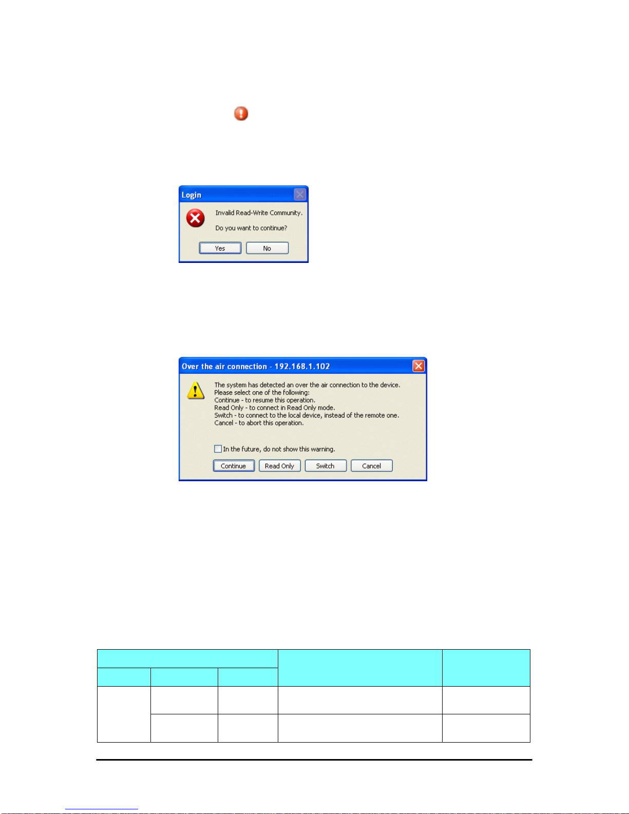
Incorrect Password Chapter 4
FA4800 User Manual Release 1.9.30 4-7
Incorrect Password
If you type an incorrect password in the Login window, you will see a warning graphic alongside the password field.
Invalid Read/Write Community String
This will result in the following message:
Figure 4-7: Invalid Community String message
Logging in to the Over-the-Air Site
You can log on to the over-the-air site of an established link (Site B in our
example). However, you will be first offered the following caution:
Figure 4-8: Logging on to an over-the-air site
Continuing without an IP Address
The FibeAir2000 Manager provides limited “offline” functionality when there
is no accessible IDU/ODU. It is primarily for setting managing computer
related parameters, running the Link Budget Calculator or viewing online
Help. The offline functionality is shown in Table 4-3 below. The table does
not show menu items grayed out.
Table 4-3: FibeAir2000 Manager: Offline Functionality
Menu level
Function Reference
Top +1 +2
File
Log Off
Return to log-on dialog. Same as Log Off
button
Exit
Exit the FibeAir2000 Manager. Same as Exit
button
Page 70
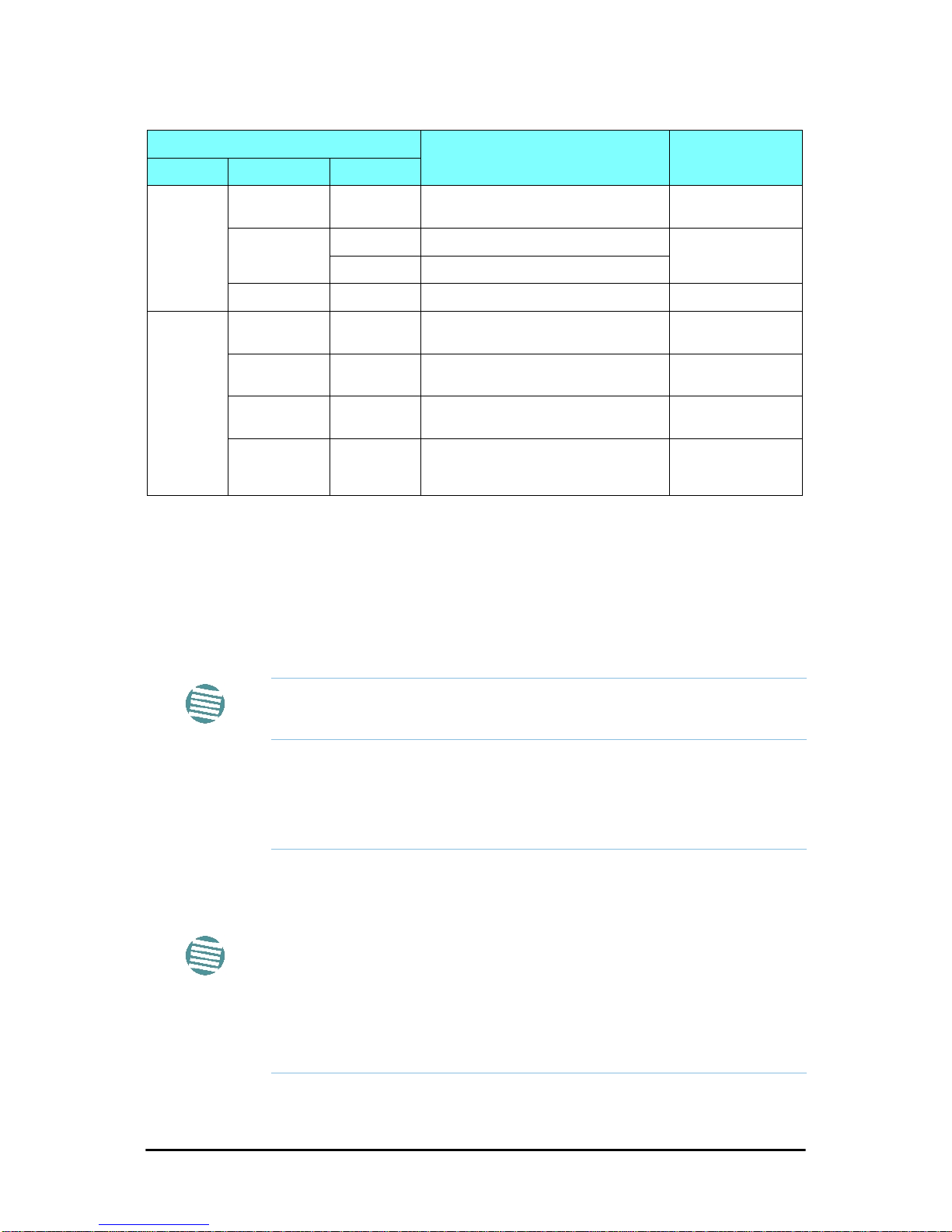
Changing the Log-On Password Chapter 4
FA4800 User Manual Release 1.9.30 4-8
Changing the Log-On Password
¾ To change the log on password:
1. From the Tools menu, select Change Password.
The Change Password dialog box appears.
2. Enter the current password, and the new password.
3. Click OK to confirm.
First steps
At this point the main window of the FibeAir2000 Manager should be displayed:
Tools
Change
Password
Change the log-on password page 4-8
Events Log
Clear Events Clear local events log
page 9-17
Save to File Save events log data to a file
Preferences Set managing computer preferences
Help
FibeAir2000
Manager Help
View online help version of the User Manual
Link Budget
Calculator
Calculator opened in default browser 21
Get Diagnostics
Information
Obtain system information page 9-1
About
FibeAir2000
Manager
FibeAir2000 Manager build information
Note
A valid log-on password must contain at least five characters excluding
SPACE, TAB, and any of “>#@|*?;.”
Note
For what follows, it is assumed that you have set the IP addresses of both
ODUs. For the purposes of illustration, we will use the following IP
addresses:
Our managing computer has its NIC set to IP address 192.168.2.100. The
log-on ODU is set to IP address 192.168.2.101 and the over-the-air ODU is
set to 192.168.2.102. The Subnet Mask for both sites is 255.255.255.0 and
the Default Gateway is left unset. We will maintain this arrangement
throughout the remainder of this manual.
Other defaults are shown in Table 4-4.
Table 4-3: FibeAir2000 Manager: Offline Functionality (Continued)
Menu level
Function Reference
Top +1 +2
Page 71
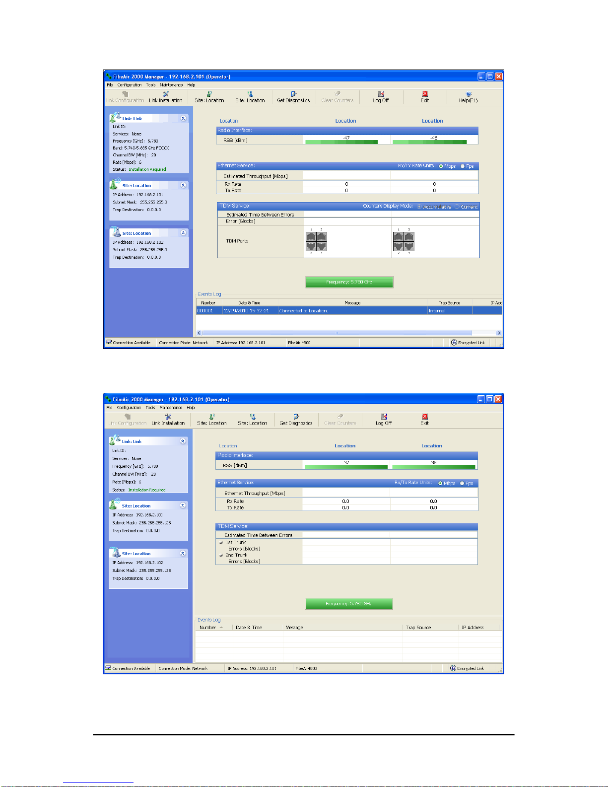
First steps Chapter 4
FA4800 User Manual Release 1.9.30 4-9
Figure 4-9: Opening FibeAir2000 Manager window prior to installation IDU-C and new style IDU-E
Figure 4-10: Opening FibeAir2000 Manager window prior to installation - old
style IDU-E
Page 72

First steps Chapter 4
FA4800 User Manual Release 1.9.30 4-10
A detailed field by field description of the contents of the FibeAir2000 Manager main window may be found in 6.
The procedure required to make the link functional has three phases:
1. Link Installation - which we will detail below.
Installation actually gets the link operational by setting the link parame-
ters. It uses a fixed channel at the lowest possible modulation, BPSK at
6.5Mbps and will work under the harsh interference condition.
2. Link Configuration - described in 7.
Configuration provides much the same functionality as Installation, but
for a running link. A fallback to Installation mode is provided for situations which cannot be handled without resetting the link, such as
antenna realignment and IDU or ODU replacement.
The Link Installation and Configuration phases are both carried out with
Wizards, which “walk you through” the processes. The Wizards are visually quite similar and will be described in detail below.
3. Site Configuration - described in 8.
Site specific configuration for each side of the link is available at any time
- under a running link or under the restricted Installation mode.
Site Configuration consists of a set of panels, which may be invoked indi-
vidually in any order, as needed.
Note
During the installation procedure, the definition of all parameters is
automatically applied to both sides of the link.
Caution
• The ODUs as supplied by Ceragon are set up with a factory default
band. If for some reason the default band needs to be changed, it
should be done before link Installation. The procedure is set out in
20.
• Use of an incorrect band may be in violation of local regulations.
Note
An installed and configured link can be returned to installation mode for reinstallation and configuration from last settings or from factory settings.
• Reversion to installation mode requires a complete break in the link
service
• Configuration mode may vary the service throughput and quality, but
without a service break
Page 73

Default FA4800 Settings Chapter 4
FA4800 User Manual Release 1.9.30 4-11
Default FA4800 Settings
The default settings of the FA4800 configuration parameters are listed in
the second column of Table 4-4 below. The third column shows the values
we use in this manual for illustrative purposes.
Table 4-4: Default Settings
Parameter Default Value Illustrative Value
Factory default band Product dependent 5.780GHz
ODU IP Address 10.0.0.120 192.168.2.101 and 102
Subnet Mask 255.0.0.0 255.255.255.0
Trap destination 0.0.0.0 0.0.0.0
FibeAir2000 Manager log-on
passwords
Observer admin
Operator admin
Installer wireless
Link ID Link EBG_20561334
Link Name Name TPSF_BTT
Site 1 Site A
Site 2 Site B
Location (per site) Location A B
Name (per site) Name Here There
Contact (per site) Person John Mary
Link Password wireless-bridge
Rate Adaptive
Ethernet Configuration Auto Detect
Radio Link Failure Actions No action
Bridge or Hub mode Hub Mode, Aging time = 300 sec
Community values
Read-write – netman
Read-only – public
Page 74

FA4800 User Manual Release 1.9.30 5-1
Chapter 5
Installing the Link
Overview
The installation is carried out using the Installation wizard. Its operation is
detailed in the following pages in a tutorial style.
For the purpose of explanation, we will set up a laboratory link with the following characteristics:
• Channel selection: Automatic
• Services: Ethernet + 3xE1 on ports 1, 2, 3 using IDU-As
The Installation wizard has seven eight steps as shown in Table 5-1 below.
Note
For new style IDU-E users: The procedure shown here is the same as for
IDU-C based links. The main window will show two trunk ports instead of
four.
Page 75
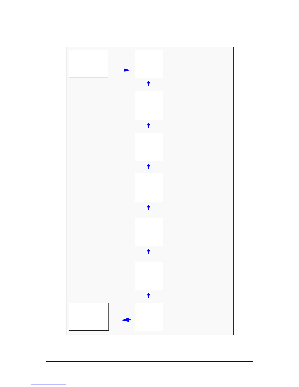
Overview Chapter 5
FA4800 User Manual Release 1.9.30 5-2
Table 5-1: Link Installation Wizard
1
Wizard welcome
2
Syste m parameters
•Link ID
•Site details
3
Channel settings - ACS
Configuration
4
HSS Settings
5
Services - Types
• Ethernet
•TDM
Adaptive or fixed, Jitter
Buffer, MHS, Ethernet
Ring, QoS
6
Set TDM Clock
Parameters
7
Wizard summary and
completion
Page 76
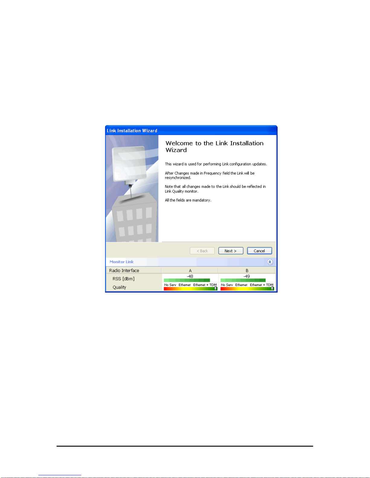
Installation Chapter 5
FA4800 User Manual Release 1.9.30 5-3
Installation
Step 1, Start the Wizard
In the tool bar of the FibeAir2000 Manager main window, click the Link
Installation button. The Link Installation button is only accessible if the
antennas are properly aligned. If this box is “grayed out”, you should align
the antennas as set out in 3 on page 3-17.
The Installation Wizard opens:
Figure 5-1: Link Installation Wizard
The bottom data area reproduces the corresponding data from the main
window - which the above panel obscures. See 6 for a field by field description of this data area.
Click Next to proceed with the installation procedure.
Step 2, System Parameters
The system dialog box opens:
Page 77
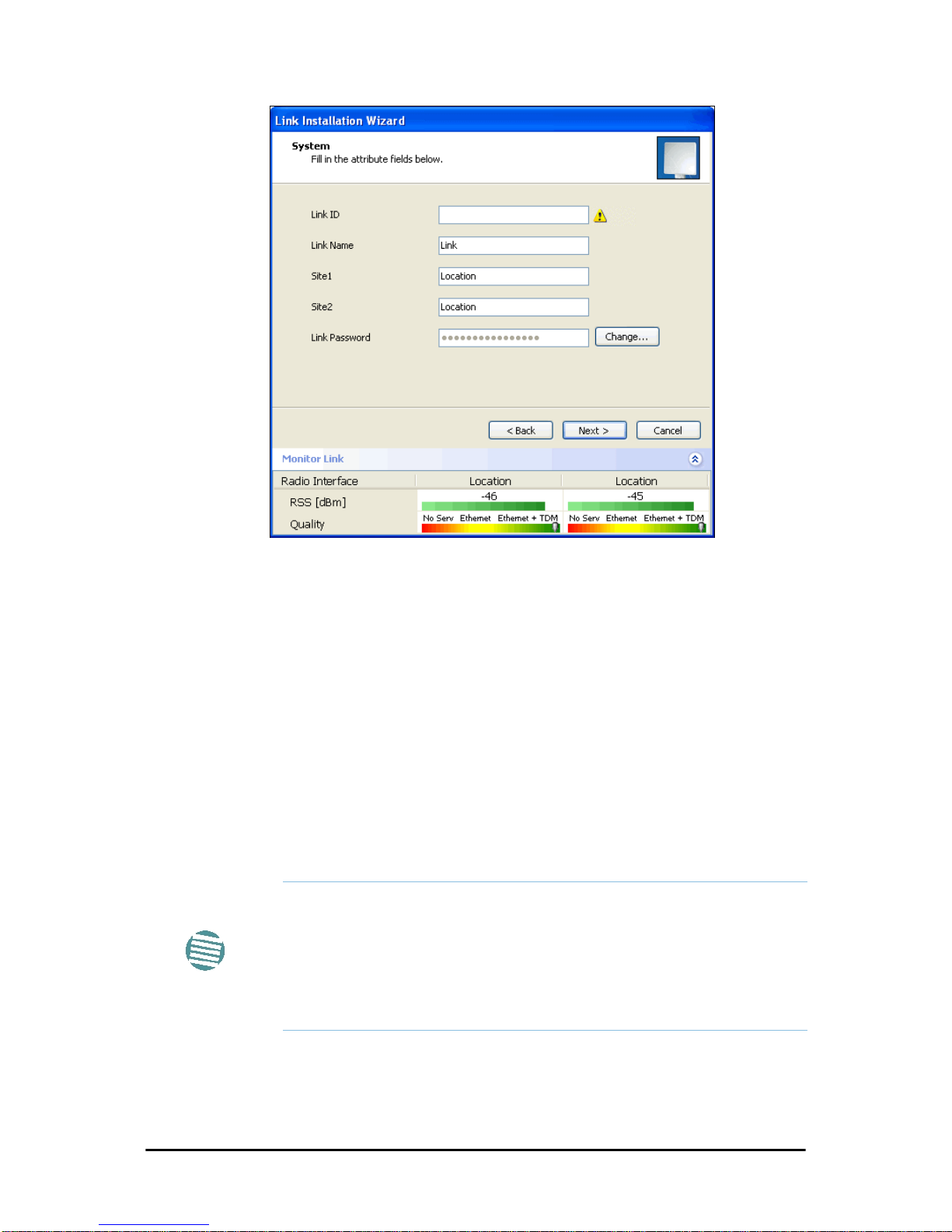
Installation Chapter 5
FA4800 User Manual Release 1.9.30 5-4
Figure 5-2: Installation Wizard, System dialog box
¾ To complete Installation Step 2:
1. Enter a Link ID. The Link ID must be identical for both ODUs in the
link, otherwise they will not communicate. The Link ID must
include at least eight alphanumeric characters. Up to 24 characters are
allowed. You should use a Link ID composed of both alphabetic and
numeric characters.
2. Enter a Link Name for the link identification. The default name is “Link”.
You should change it.
3. Enter names for Site 1 and Site 2. The default names are both “Location”.
You should change them. Throughout this manual, we use A for Site 1
and B for Site 2.
4. Optionally enter a new Link Password.
Here is our completed System panel:
Note
If the Link Password is incorrect a link is established but configuration
cannot be performed and no services are available. A new link password
may be obtained from Ceragon Customer Support or use the alternative
password supplied with the product.
The link password is peculiar to the link itself and should not be confused
with the FibeAir2000 Manager log on password.
Page 78
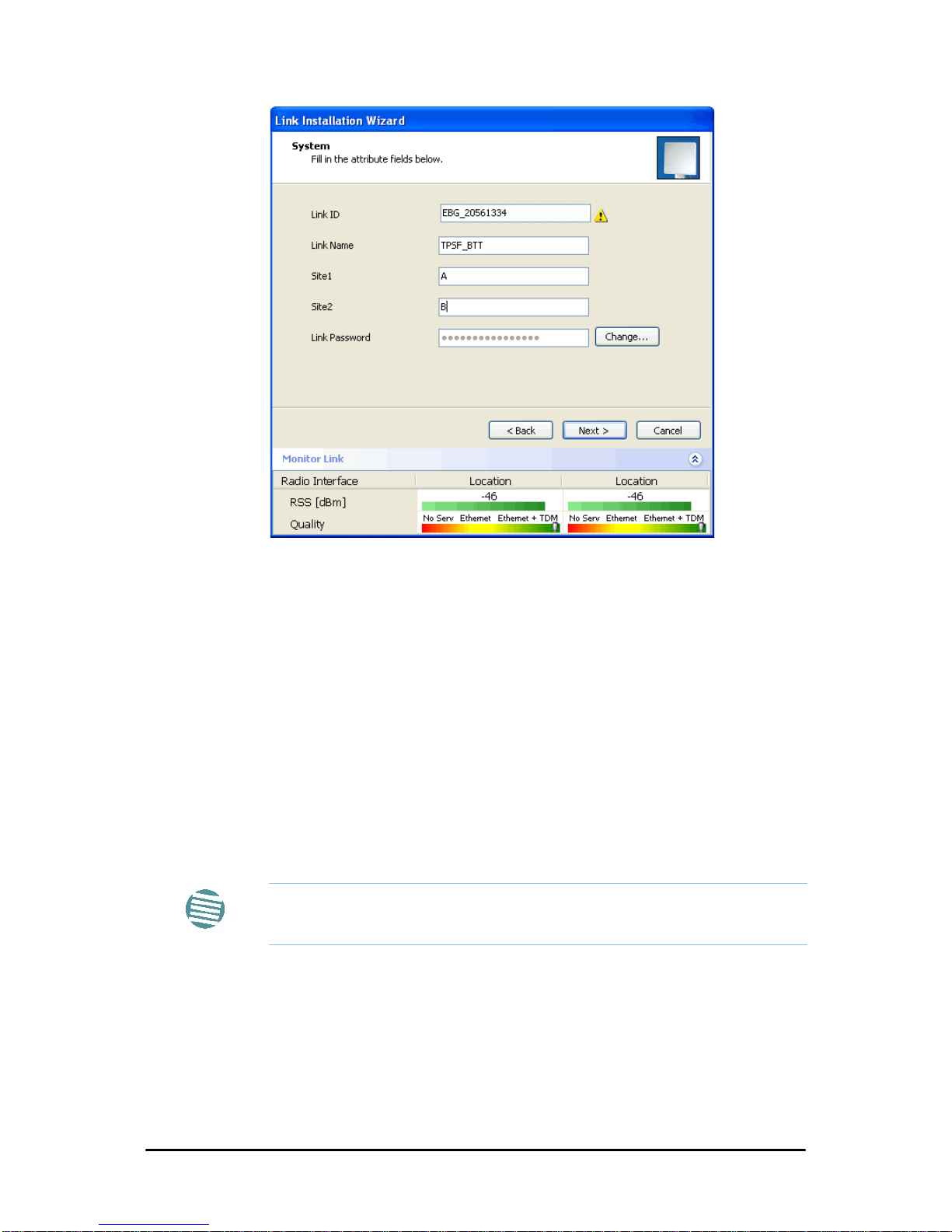
Installation Chapter 5
FA4800 User Manual Release 1.9.30 5-5
Figure 5-3: Installation Wizard, System dialog box filled out
5. Click Next.
The default link with a rate of 6.5 Mbps is evaluated.
The Channel Setting dialog box appears. Proceed to Channel Settings,
below.
Changing the Link Password
The default password is
wireless-bridge
. Optionally, you can change the
link password as explained here.
¾ To change the link password:
1. Click the Change button in the System dialog box.
The Change Link Password dialog box opens.
Note
Use the Hide characters check box for maximum security
Page 79
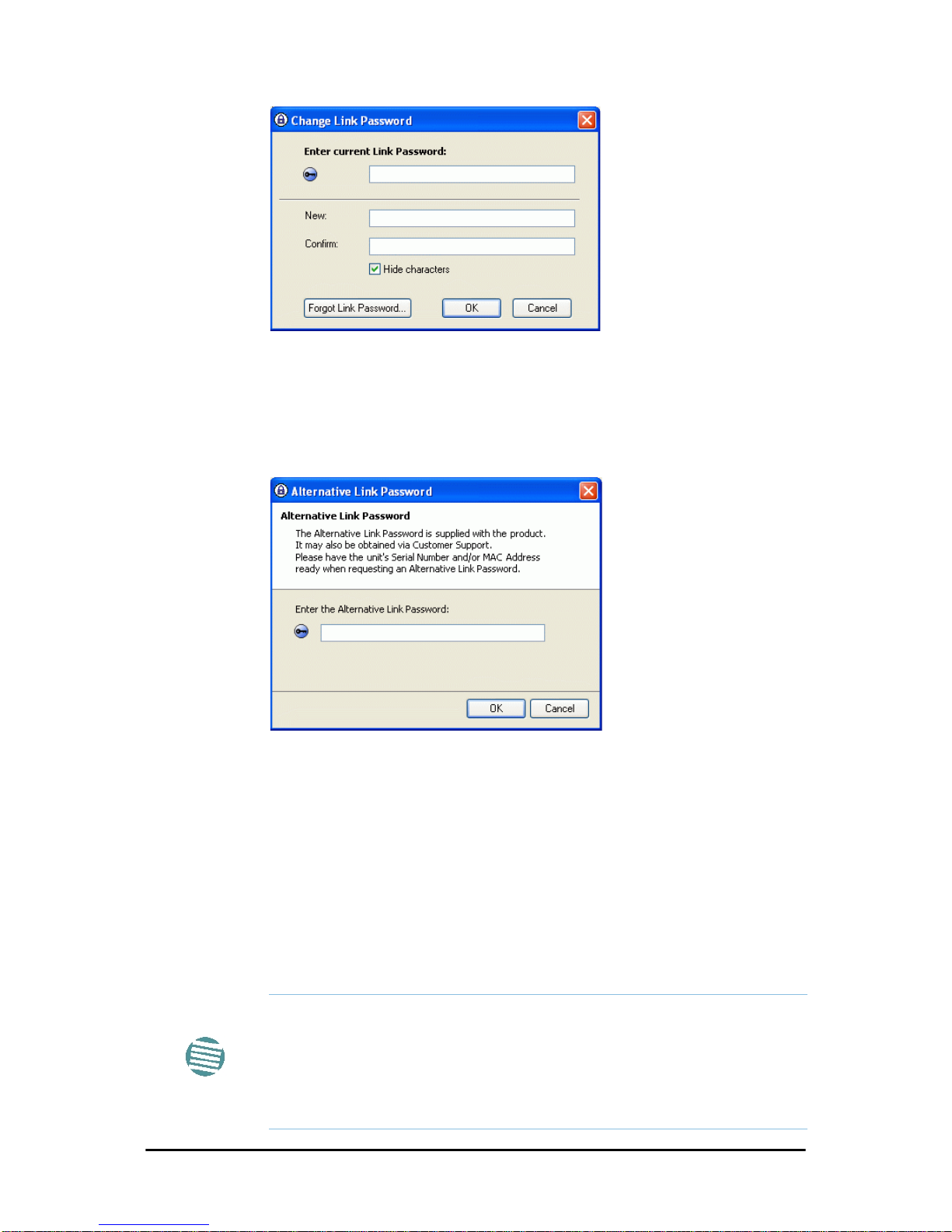
Installation Chapter 5
FA4800 User Manual Release 1.9.30 5-6
Figure 5-4: Change Link Password dialog box
2. Enter the current link password (The default link password for a new
ODU is
wireless-bridge
).
If you have forgotten the Link Password, click the Forgotten Link Password button. The following window is displayed:
Figure 5-5: Lost or forgotten Link Password recovery
Follow the instructions to use the Alternative Link P assword, and click OK
to finish. You are returned to the window in Figure 5-4 above. Continue
with the next step.
3. Enter a new password.
4. Retype the new password in the Confirm field.
5. Click OK.
6. Click Yes when asked if you want to change the link password.
7. Click OK at the
Password changed
success message.
Note
• A link password must contain at least eight but no more than 16
characters excluding SPACE, TAB, and any of “>#@|*?;.”
• Restoring Factory Defaults returns the Link Password to
wireless-
bridge
.
• If the link is inactive, then the link password may also be changed
from the Site Configuration dialogs. See page 8-13.
Page 80
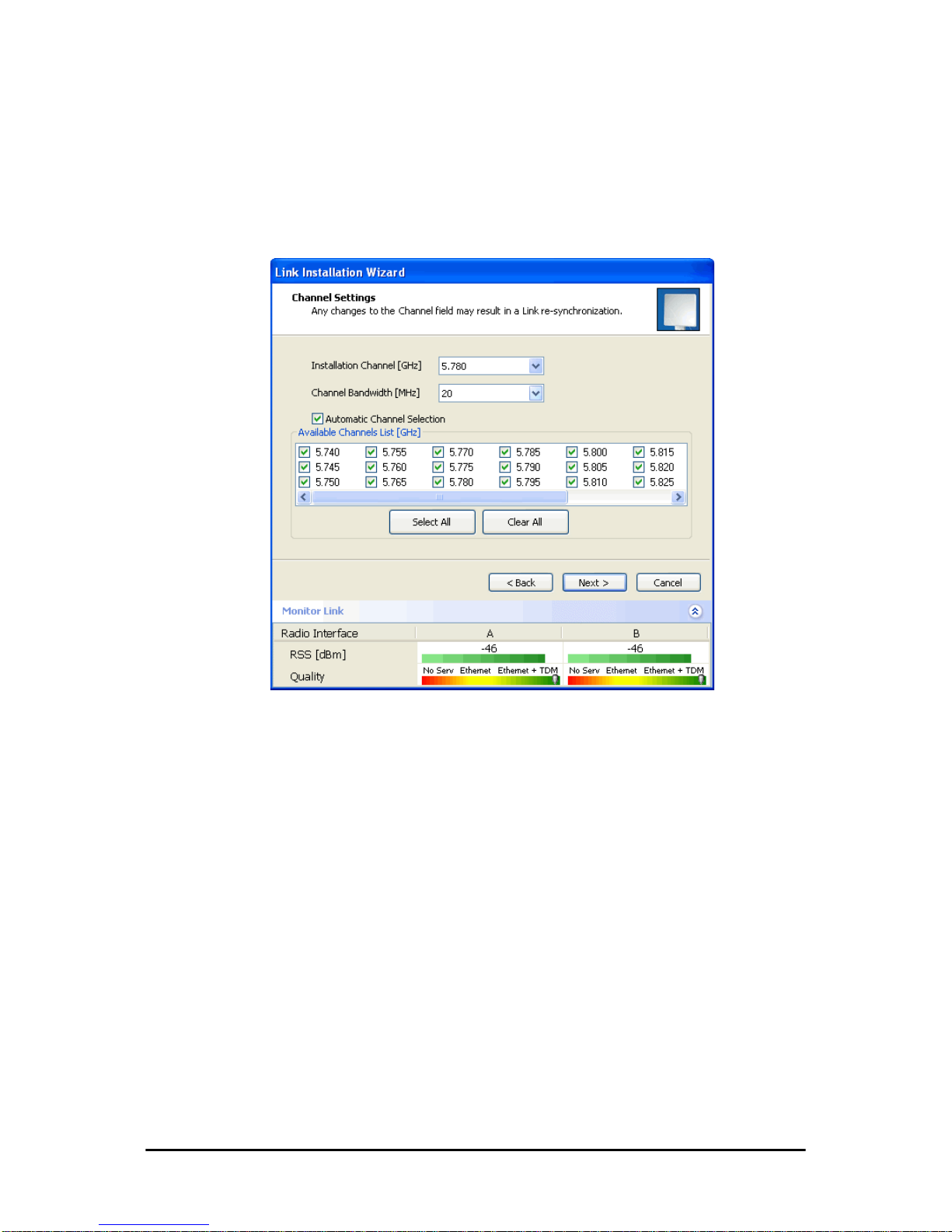
Installation Chapter 5
FA4800 User Manual Release 1.9.30 5-7
Step 3, Channel Settings
FA4800 systems have a feature called Automatic Channel Selection (ACS).
In the event of sync loss, ACS chooses the first available channel in a list of
monitored channels nominated in the Channel settings window of
Figure 5-6 below. A channel switch takes place sufficiently fast as to
ensure no loss of service.
Figure 5-6: Channel Settings - Automatic Channel Selection
The default frequency for the product is shown.
¾ To select channels to be used by the link:
1. Select the installation frequency from the Installation Channel box.
Page 81
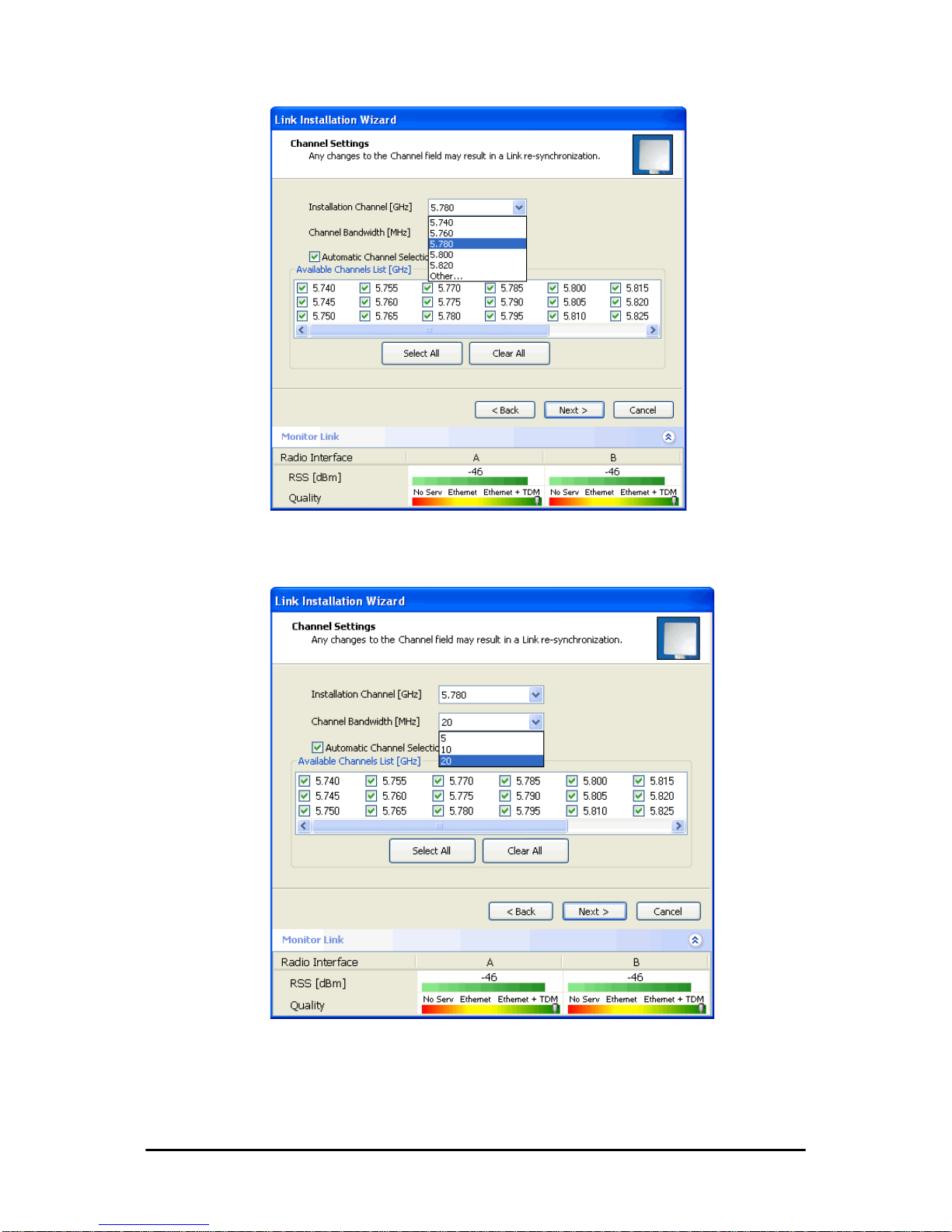
Installation Chapter 5
FA4800 User Manual Release 1.9.30 5-8
Figure 5-7: Channel Settings - Showing available installation rates
2. Choose the required Channel Bandwidth.
Figure 5-8: Channel Settings - Showing available Channel Bandwidths
Page 82
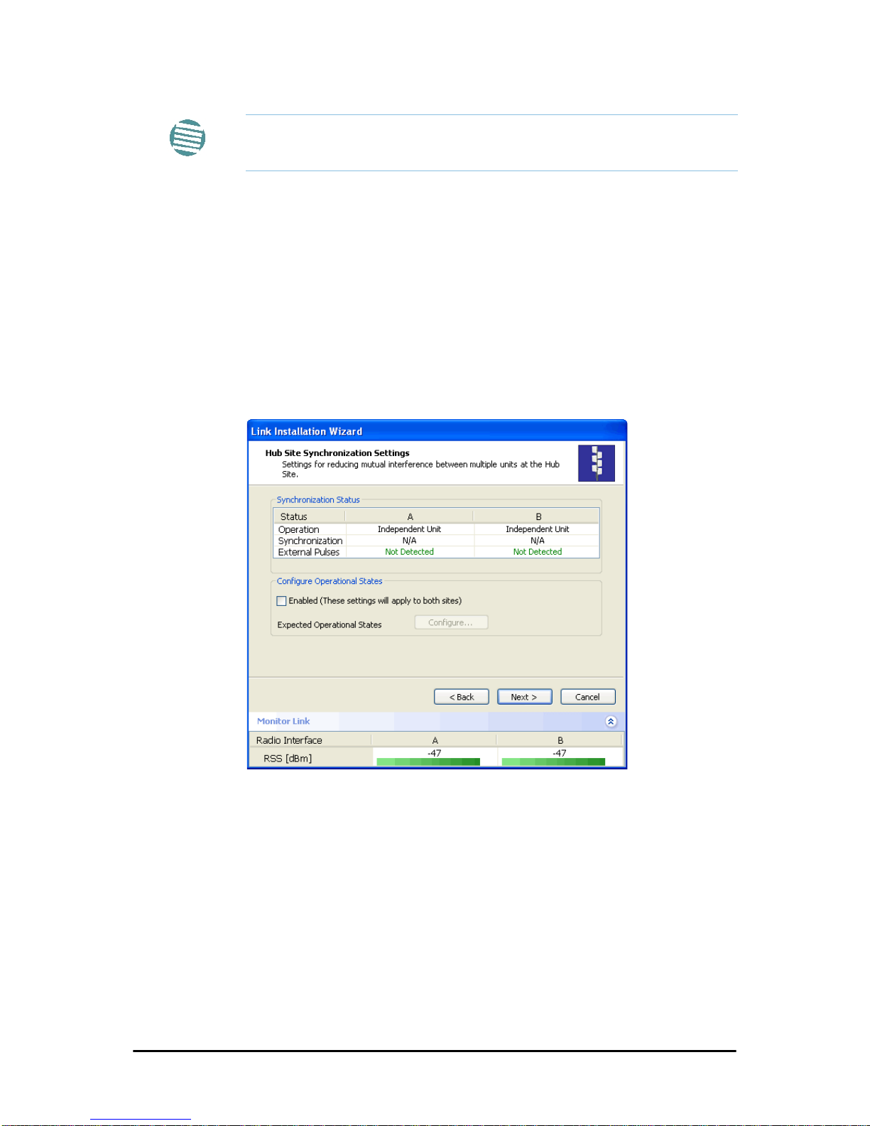
Installation Chapter 5
FA4800 User Manual Release 1.9.30 5-9
3. Click the check box if Automatic Channel Selection is required.
4. The Available Channels List contains all of the allowable channels for the
link. Check the channels that can be automatically selected.
Selecting a new channel causes the system quality to change. The Quality bar provides an indication of the link quality from No serv(ice) (red)
to Ethernet + TDM (green) as shown in the bottom of Figure 5-7
above.
5. Click Next.
Step 4, Hub Site Synchronization Settings
Figure 5-9: HSS Settings
The Synchronization Status dialog box displays the current status of each
side of the link. See 10 for instructions about installing and configuring collocated links. If you do not require HSS, click Next.
Step 5, Services
The Services dialog appears:
Note
ACS is only supported for a Channel Bandwidth of 20 MHz.
Page 83
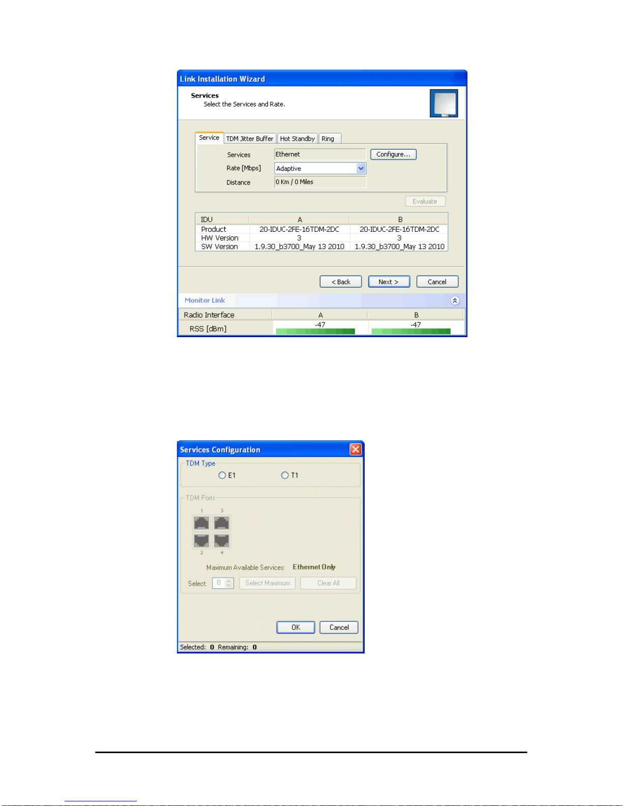
Installation Chapter 5
FA4800 User Manual Release 1.9.30 5-10
Figure 5-10: Services and Rates
TDM Services selection
¾ To select services:
1. Click the Configure button. The TDM services dialog is displayed:
2. Using the TDM Type radio buttons, choose E1 or T1. You are now able to
select the required service ports:
Page 84
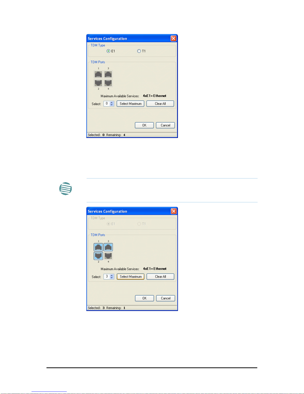
Installation Chapter 5
FA4800 User Manual Release 1.9.30 5-11
Figure 5-11: TDM service port selection
3. Use the spin button to choose consecutive service ports, the Select
Maximum button to choose all available ports.
Figure 5-12: TDM Service port selection - seven services selected
4. Click OK. You are returned to the Services and rates dialog of
Figure 5-14. It is updated to reflect your choice.
Note
• Ethernet is always selected.
• The maximum available services will be reduced in accordance with
actual air interface capacity.
Page 85
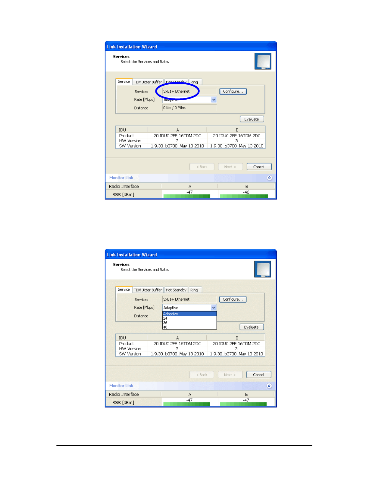
Installation Chapter 5
FA4800 User Manual Release 1.9.30 5-12
Figure 5-13: Services and Rates - Services chosen
Modulation Rate Selection
You may choose a specific modulation rate or use Adaptive.
Figure 5-14: Services and Rates dialog: Available rates
Page 86
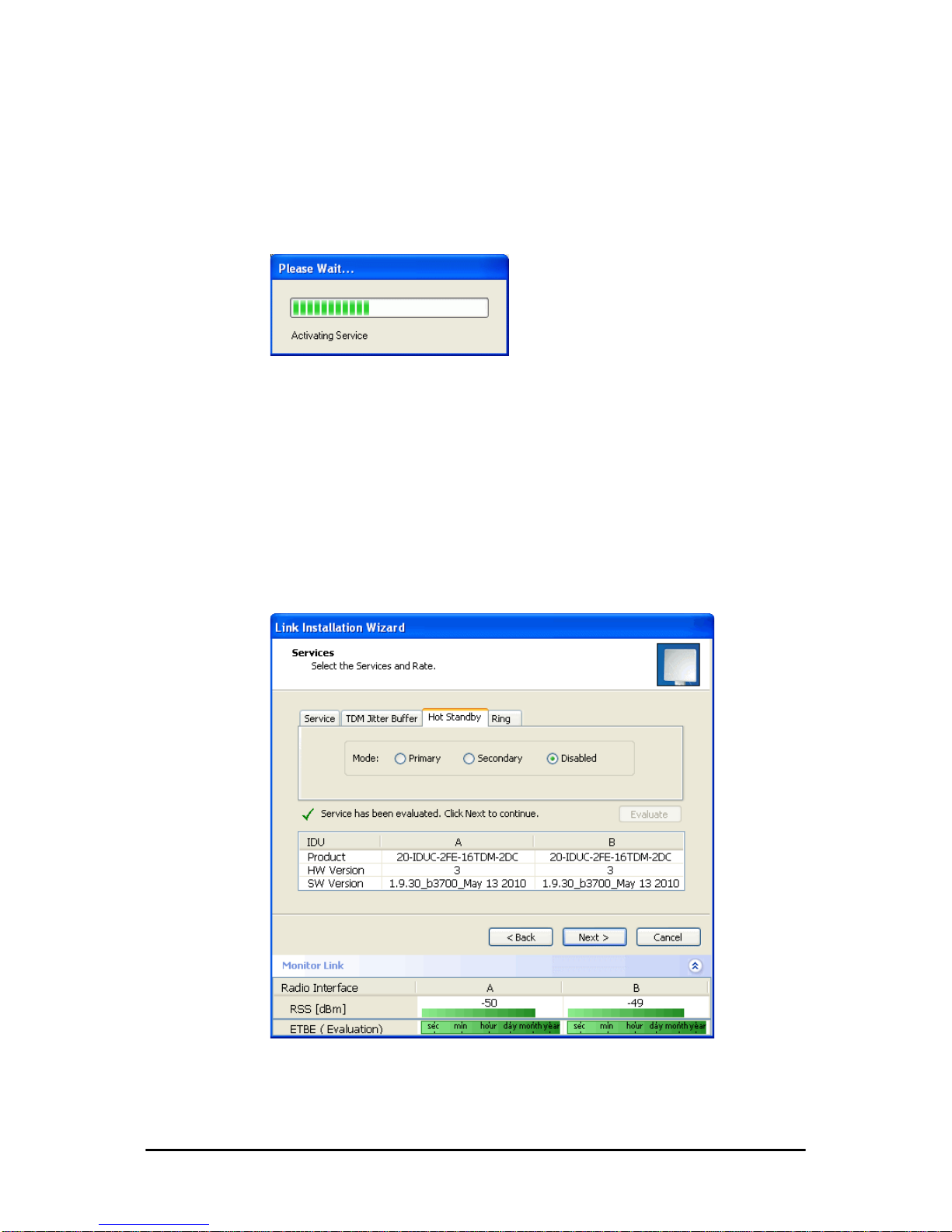
Installation Chapter 5
FA4800 User Manual Release 1.9.30 5-13
¾ To choose a modulation rate:
1. Choose Adaptive or one of the available rates.
2. Click Evaluate to continue or click the TDM Jitter Buffer tab to set the
TDM Jitter Buffer (see next section).
The service is activated as show below:
You are returned to the Services and rates dialog of Figure 5-14.
Setting Monitored Hot Standby Mode
If you are not using Hot Standby Mode, you may skip this section.
T o install and use the Hot Standby feature, see 12. The following procedure
can be used to switch links between primary and secondary or to disable
the mode.
¾ To set the Hot Standby Mode:
1. Click the Hot Standby tab. The following dialog appears:
Figure 5-15: Choosing Hot Standby Mode
2. Click the radio button to make this link primary or secondary.
Page 87
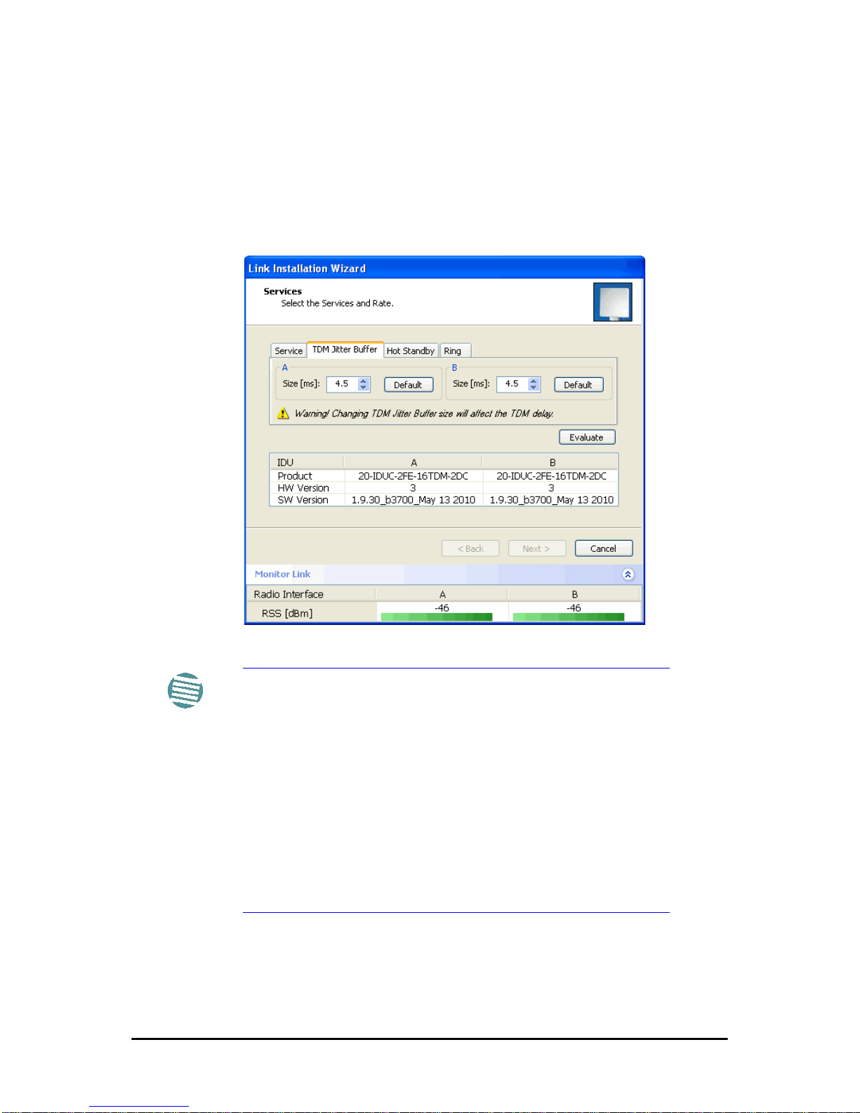
Installation Chapter 5
FA4800 User Manual Release 1.9.30 5-14
Ethernet Ring
To install and use the Ethernet Ring feature, see 13.
Setting the TDM Jitter Buffer
¾ To set the TDM Jitter Buffer size:
1. Click the TDM Jitter Buffer tab. The following dialog appears:
Figure 5-16: TDM Jitter Buffer Configuration
Note
• The receiver jitter buffer for each site can be enlarged,
thereby increasing system resistance to interference (the
larger the jitter buffer, the longer the interference period
that the system will overcome without TDM errors).
• You can also decrease the jitter buffer to decrease the sys-
tem delay.
• The jitter buffer can be configured between 2.0 and 16.0
ms.
• After setting the new value you must evaluate the expected
quality. During the evaluation the ETBE (Expectecd Time
Between Errors) bar is displayed. You select either Next,
which performs the change or Back to cancel the change.
Notice that the Jitter Buffer is configured per site.
Page 88
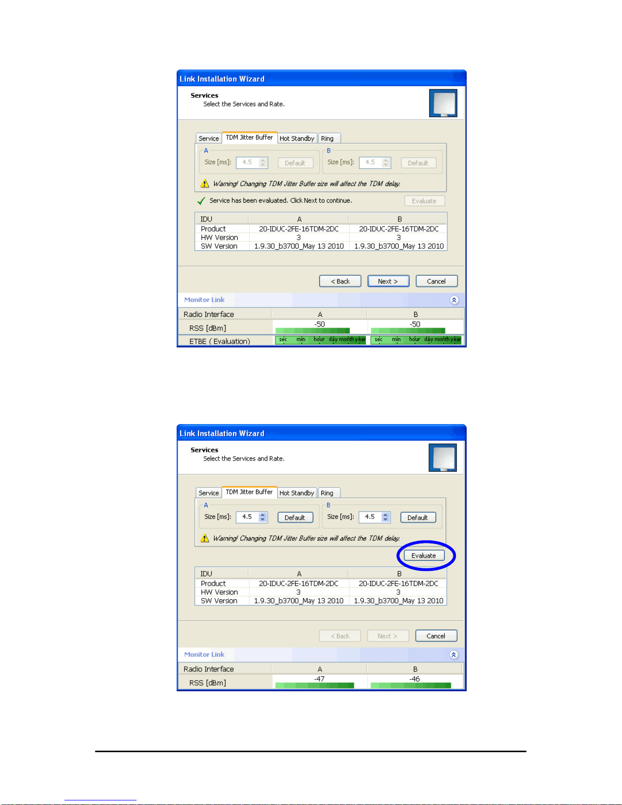
Installation Chapter 5
FA4800 User Manual Release 1.9.30 5-15
Figure 5-17: TDM Jitter Buffer Configuration - ETBE evaluation bar
2. After setting the jitter buffer size, if grayed out, the Evaluate button is
enabled while both Back and Next are disabled as shown in the next
figure:
Figure 5-18: Services and TDM delay set - link ready for evaluation
Page 89
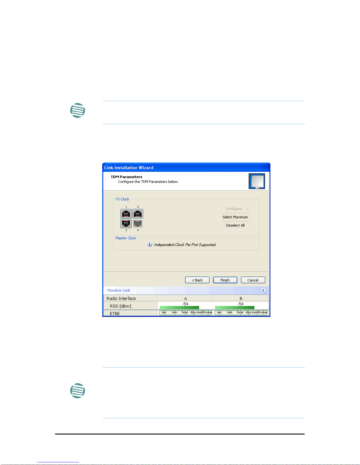
Installation Chapter 5
FA4800 User Manual Release 1.9.30 5-16
3. You ma y make any further changes to the Service Configuration
or the Jitter buffer. When you are satisfied, click the Evaluate.
The optimum transmission rate for the selected services is evaluated.
Following a short delay for processing, Back and Next are
enabled.
4. Click Next to continue.
Step 6, TDM Clock Configuration
The following dialog is displayed:
Figure 5-19: TDM Parameters Configuration (1)
¾ To configure TDM clock parameters:
1. For any individual port, click it. For the same parameters for all
ports, click the Select Maximum tag.
Note
The transmission rates used by FA4800 are shown in Table 5-4 above.
Note
• Select Maximum will select the maximum number of services that
were configured for the air interface for configuration
• Deselect All unconditionally deselects all of the services for configuration
• Without selecting anything, right-clicking any port will cause the
appearance of the drop down list of Figure 5-30 below
Page 90
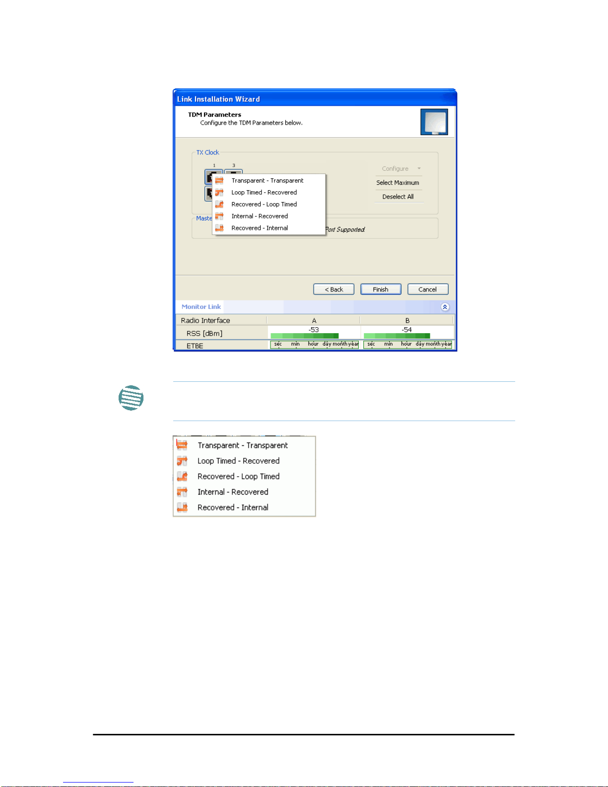
Installation Chapter 5
FA4800 User Manual Release 1.9.30 5-17
2. Click Configure. The following drop down list is displayed:
3. Click the required parameter. Their meanings are as follows:
Figure 5-20: TDM Parameters
Transparent/Transparent
The clock at Site A regenerates the clock from Site B and
vice versa.
Loop time/Recover
The Site A port receive-clock is used as the transmit-clock
for that port on both sides of the link.
Recover/Loop time
The Site B port receive-clock is used as the transmit-clock
for that port on both sides of the link.
Internal/Recover
Note
Please keep in mind that what follows is
per port
.
Page 91
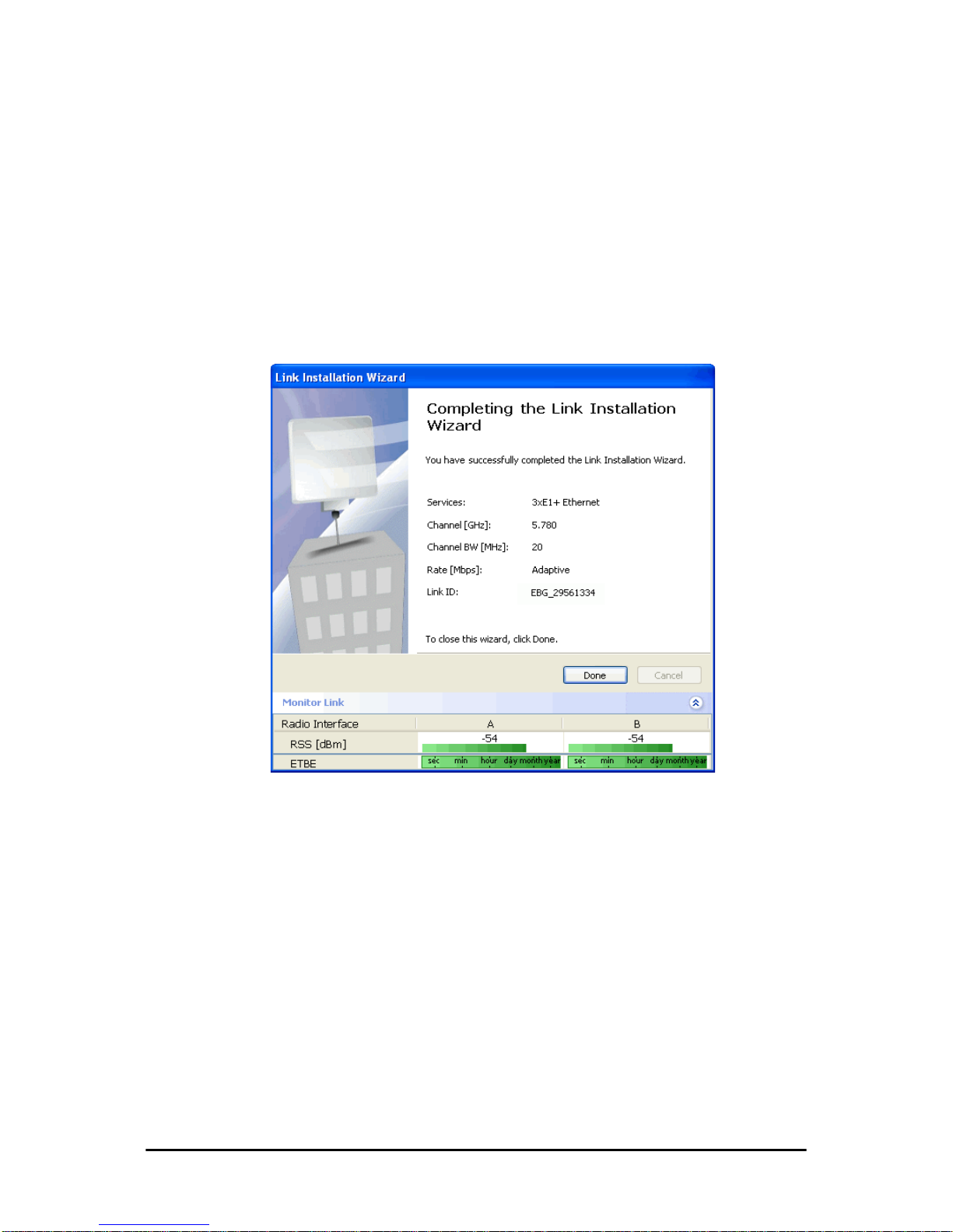
Installation Chapter 5
FA4800 User Manual Release 1.9.30 5-18
The Site A port uses its internal oscillator to generate its
transmit clock while the Site B port regenerates the clock
received at the Site A port.
Recover/Internal
The Site B port uses its internal oscillator to generate its
transmit clock while the Site A port regenerates the clock
received at the Site B port.
4. Click Finish to complete the wizard.
Step 7, Installation Summary and Exit
Figure 5-21: Installation Wizard Exit Summary
Click Done to return to the main window.
The main window now reflects the installation:
Page 92
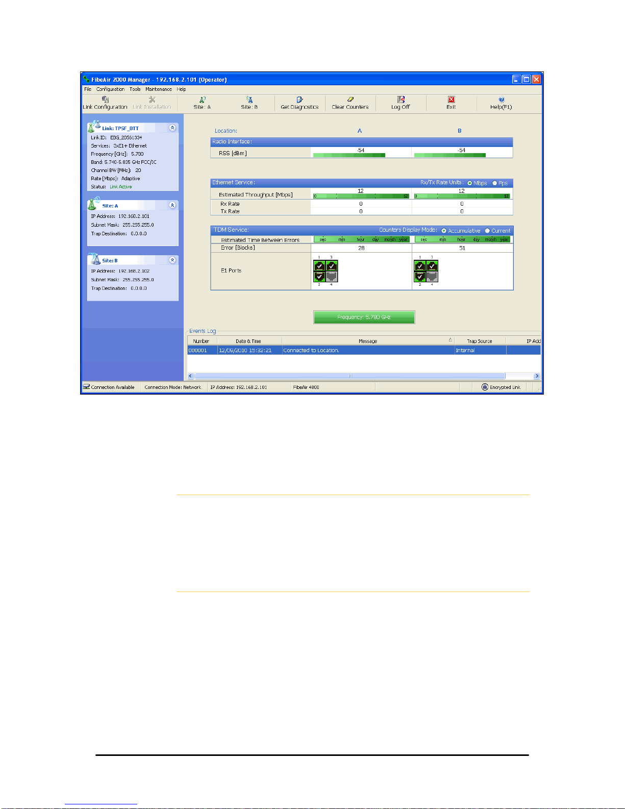
Installation Chapter 5
FA4800 User Manual Release 1.9.30 5-19
Figure 5-22: Main window of the Manager after installation with loaded
trunks
¾ To verify the installation:
• Verify that the Received Signal Strength (RSS) is according to expected
results as determined by the Link Budget Calculator.
Caution
Installation mode, as described above, may be re-entered using Site:A or
Site:B and Installation Mode in the Site Configuration dialog. Some
Installation mode functionality may cause a break in, or degrade link
service.
If you can accomplish link changes without affecting the service, always
prefer to use Configuration mode, described in 7.
Page 93

FA4800 User Manual Release 1.9.30 6-1
Chapter 6
The FibeAir2000 Manager:
Main Window
One Manager for all Ceragon Radio Products
The FibeAir2000 Manager application is largely generic to all Ceragon Radio
Products.
Functionality differences are minimal according to radio series (FA4800 and
FibeAir 2000) capabilities.
The Main Window of the FibeAir2000 Manager
Ensure that the FibeAir2000 Manager is running.
The main window should look similar to that in Figure 6-1:
Page 94
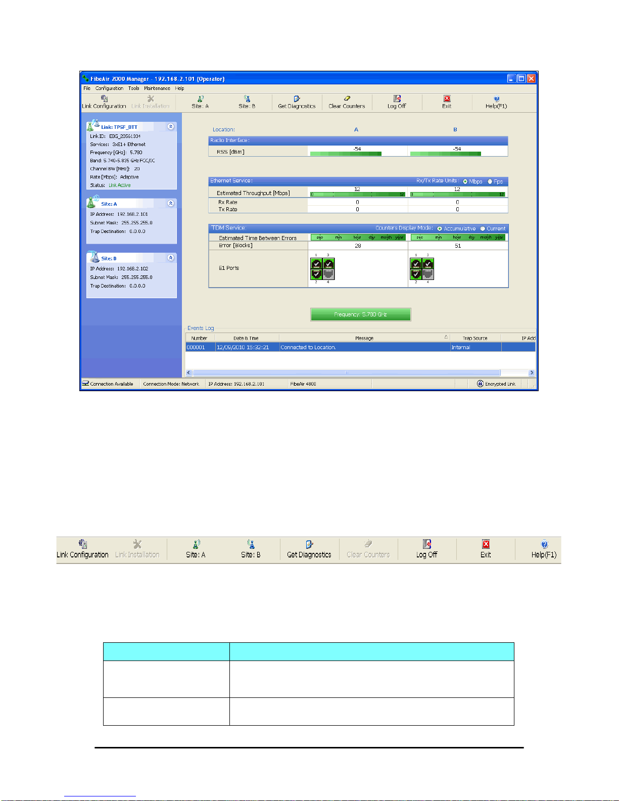
The FibeAir2000 Manager Toolbar Chapter 6
FA4800 User Manual Release 1.9.30 6-2
Figure 6-1: Main window, Wireless Link is Active
The main window of the FibeAir2000 Manager contains a large amount of
information about the link. Before proceeding to details of link configuration
we set out the meaning of each item in the main window.
The FibeAir2000 Manager Toolbar
In configuration mode, the FibeAir2000 Manager toolbar contains the following buttons:
In Installation mode, Link Configuration is grayed out and Link Installation
is open.
The button functions are set out in Table 6-1:
Table 6-1: FibeAir2000 Manager Toolbar
Item Description
Link Configuration
Changes configuration parameters of an operating wireless link; assigns text files
for storing alarms, statistics and configuration data. This button is disabled
until a link installation has been completed
Link Installation
Performs preliminary configuration of the system. This button is disabled after
the link is installed
Page 95
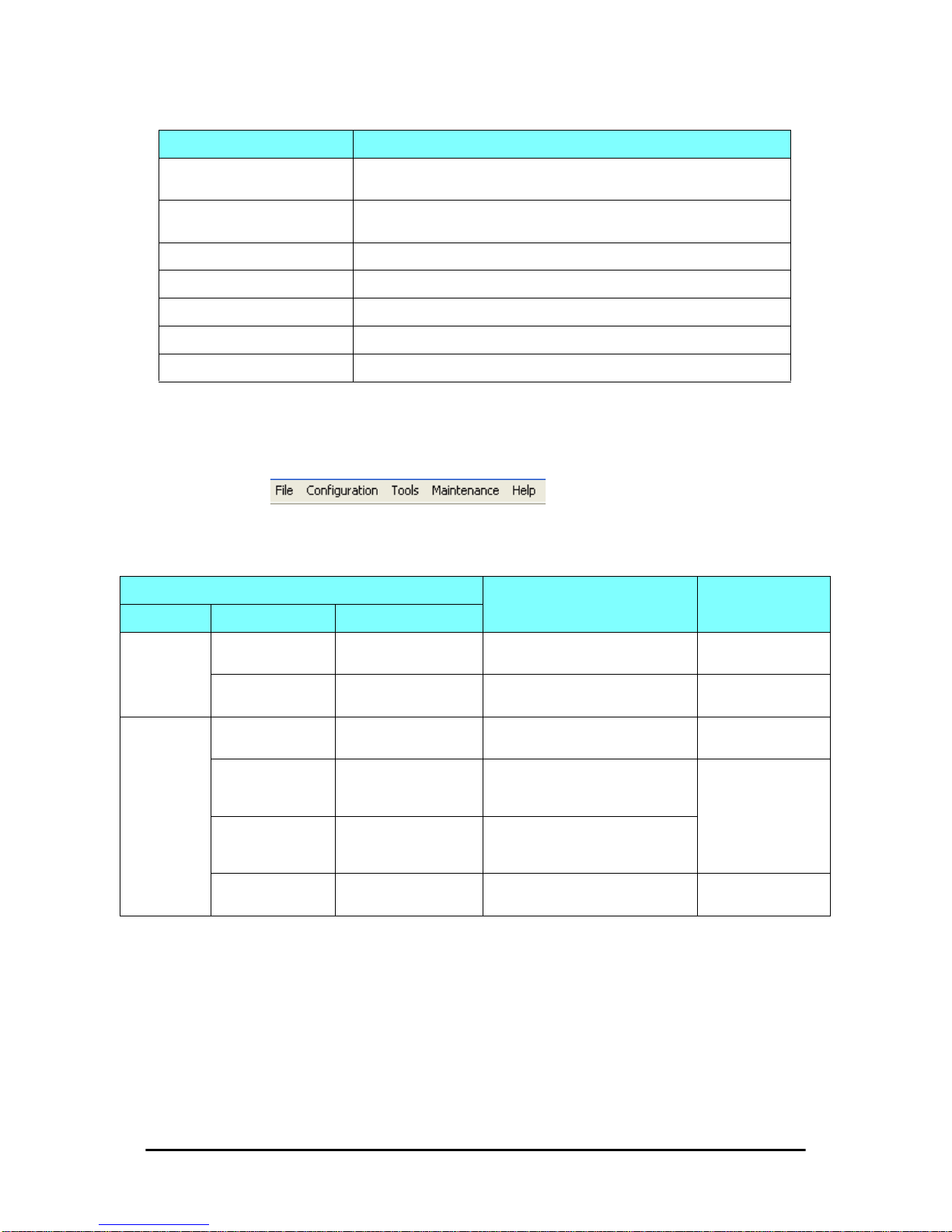
Main Menu Functionality Chapter 6
FA4800 User Manual Release 1.9.30 6-3
Main Menu Functionality
The main menu contains the following items:
The FibeAir2000 Manager menu functionality is displayed in Table 6-2.
Site: <Site 1 name>
Opens the Site configuration dialog for Site 1. Same as Configuration | 1
Configure <Site 1 name>
Site: <Site 2 name>
Opens the Site configuration dialog for Site 2. Same as Configuration | 2
Configure <Site 2 name>
Get Diagnostics Obtain system information
Clear Counters Clears TDM error blocks counters. Disabled for Ethernet-only link
Log off Closes the current session and logs off FibeAir2000 Manager
Exit Exits FibeAir2000 Manager
Help Opens Help on the use of contextual online help
Table 6-2: FibeAir2000 Manager main menu functionality
Menu level
Function Reference
Top +1 +2
File
Log Off
Return to log-on dialog. Same as Log
Off button
Exit
Exit the FibeAir2000 Manager. Same
as Exit button
Configuration
Link Configuration
Run the Configuration Wizard. Not
available in Installation Mode
Chapter 7
1 Configure <Site 1
name>
Opens the Site configuration di alog for
Site 1. Has a path to return to
Installation Mode
Chapter 8
2 Configure <Site 2
name>
Opens the Site configuration di alog for
Site 2. Has a path to return to
Installation Mode
Link Installation
Runs the Installation Wizard. Not
available in Configuration Mode
Chapter 5
Table 6-1: FibeAir2000 Manager Toolbar (Continued)
Item Description
Page 96

Elements of the FibeAir2000 Manager Main Window Chapter 6
FA4800 User Manual Release 1.9.30 6-4
Elements of the FibeAir2000 Manager Main Window
Link details pane
The Link details pane on the left is split into three sections, which are
largely self explanatory. The top section summarizes information about the
link:
Tools
Performance
Monitoring Report
On screen and printable
Chapter 9
Active Alarms
1 <Site 1 name>
Shows active alarms for <Site 1
name>
2 <Site 2 name>
Shows active alarms for <Site 1
name>
Recent Events Displays recent events by site
Software Upgrade Upgrade ODU firmware Chapter 14
Spectrum View Not available for FA4800
Change Band
(Installer only)
Change the link band Chapter 20
Change Password Change the log-on password dialog page 4-9
Events Log
Clear Events Clear local events log
page 9-17
Save to File Save events log file
Preferences Local preferences dialog
Maintenance
Clear counters Clear TDM counters
Loopbacks Set TDM loopbacks page 9-4
Reset
1 <Site 1 name> Reset <Site 1 name> ODU
2 <Site 2 name> Reset <Site 2 name> ODU
Help
FibeAir2000
Manager Help
View help on online help
Link Budget
Calculator
Calculator opened in default browser Chapter 21
Get Diagnostics
Information
Obtain system information page 9-1
About FibeAir2000
Manager
Manager build and system information
Table 6-2: FibeAir2000 Manager main menu functionality (Continued)
Menu level
Function Reference
Top +1 +2
Page 97
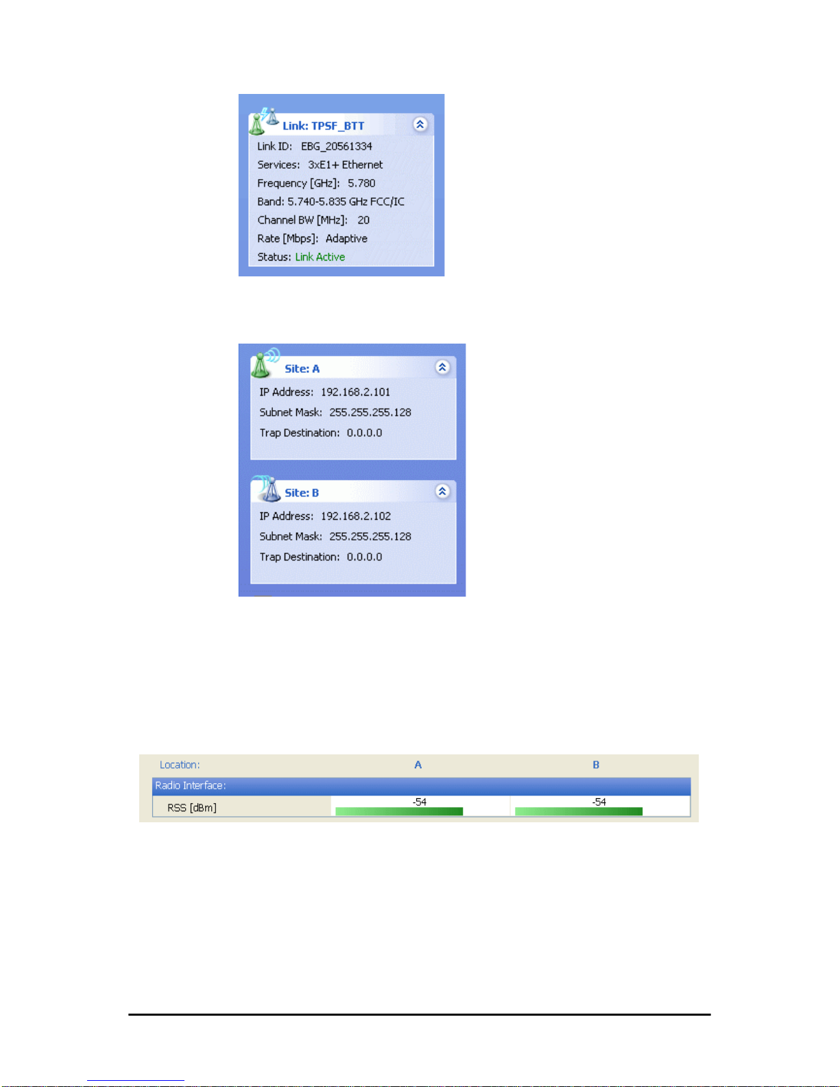
Elements of the FibeAir2000 Manager Main Window Chapter 6
FA4800 User Manual Release 1.9.30 6-5
For Link status possibilities and color codes, see Table 9-2
.
The two lower left panels show basic link site details:
The three fields for each site are user definable. see page 8-7
ff
.
The Monitor pane
The monitor pane, is the main source of real time information about link
performance at both link sites. It includes the following panes (top to bottom):
• Radio Interface, Received Signal Strength (RSS) in dBm:
• Ethernet Service:
Page 98
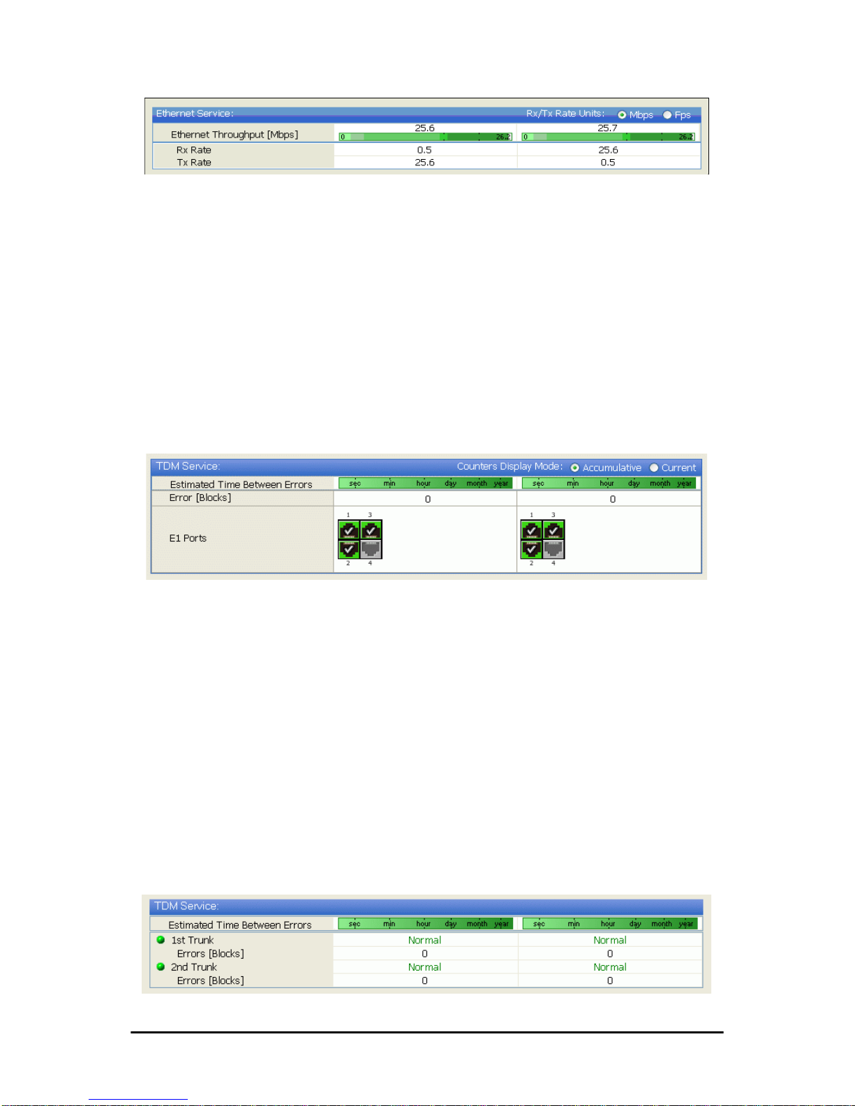
Elements of the FibeAir2000 Manager Main Window Chapter 6
FA4800 User Manual Release 1.9.30 6-6
•
Estimated Ethernet Throughput:
The numbers are the current
calculated throughputs at each site. The colored bars (with
numbers) indicate the maximum possible throughput having
regard for air conditions.
•
Rx and Tx Rates:
The Rx and Tx rates are the receive and
transmit rates on the LAN side of each ODU, not the air side.
For a balanced link, the Rx and Tx rates at the LAN side of Site
A will match the Tx and Rx rates at the LAN side of Site B
respectively. In all cases, The LAN side Rx rate shown will be
the same as the air side Tx rate for each individual ODU.
Actual Ethernet traffic received and transmitted r ates per site, is
in Mbps of Fps, selectable in the panel title bar.
• TDM Services: IDU-C and new style IDU-E:
• The title bar enables you to switch between Accumulative and
Current view.
• Immediately below the title bar is displayed the Estimated Time
Between Errors. It is zeroed by the Clear Counters button in
the tool bar.
• Error block count is shown immediately above the active TDM
channels display.
• The color of the TDM ports reflects their current status:
•Green - Operational
• Red - Error: LOS for loss of signal and AIS for Alarm Indication Signal
• Yellow - Loopback
•Gray - Inactive
• TDM Services: IDU E/R
Page 99
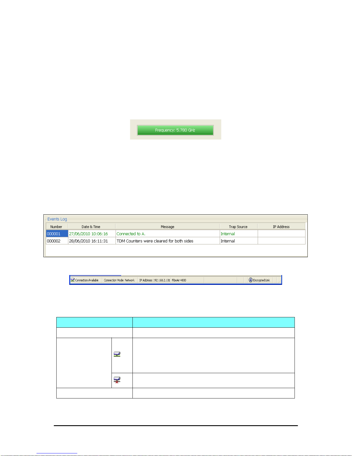
Elements of the FibeAir2000 Manager Main Window Chapter 6
FA4800 User Manual Release 1.9.30 6-7
• For each Trunk the line status and Error block count is displayed. It is zeroed by the Clear Counters button in the tool
bar. The line status is color coded and may be one of:
•Green - Normal
• Red - Error: LOS for loss of signal and AIS for Alarm Indication Signal
• Yellow - loopback
• Frequency box: It shows the link frequency. The color of the box
indicates the status
• Green is an active link
• Red is an inactive link
• Magenta indicates an authentication or compatibility problem
• Brown indicates severe compatibility problem
Events Log
The Events Log, stores alarms generated from both sides of the link and is
detailed in Chapter 9.
Status Bar
The Status bar, displays the following icons:
Table 6-3: Status bar indicators
Icon or Label Purpose
Connectivity Shows if FibeAir2000 Manager is communicating with the ODU.
Connection available
Connection mode to the ODU
• Over-the-Air connection - using the IP address of the remote unit.
• Local connection - direct connection to the IDU without using an IP
address.
• Network connection - through a LAN
ODU unreachable
IP Address Log on IP address
Page 100
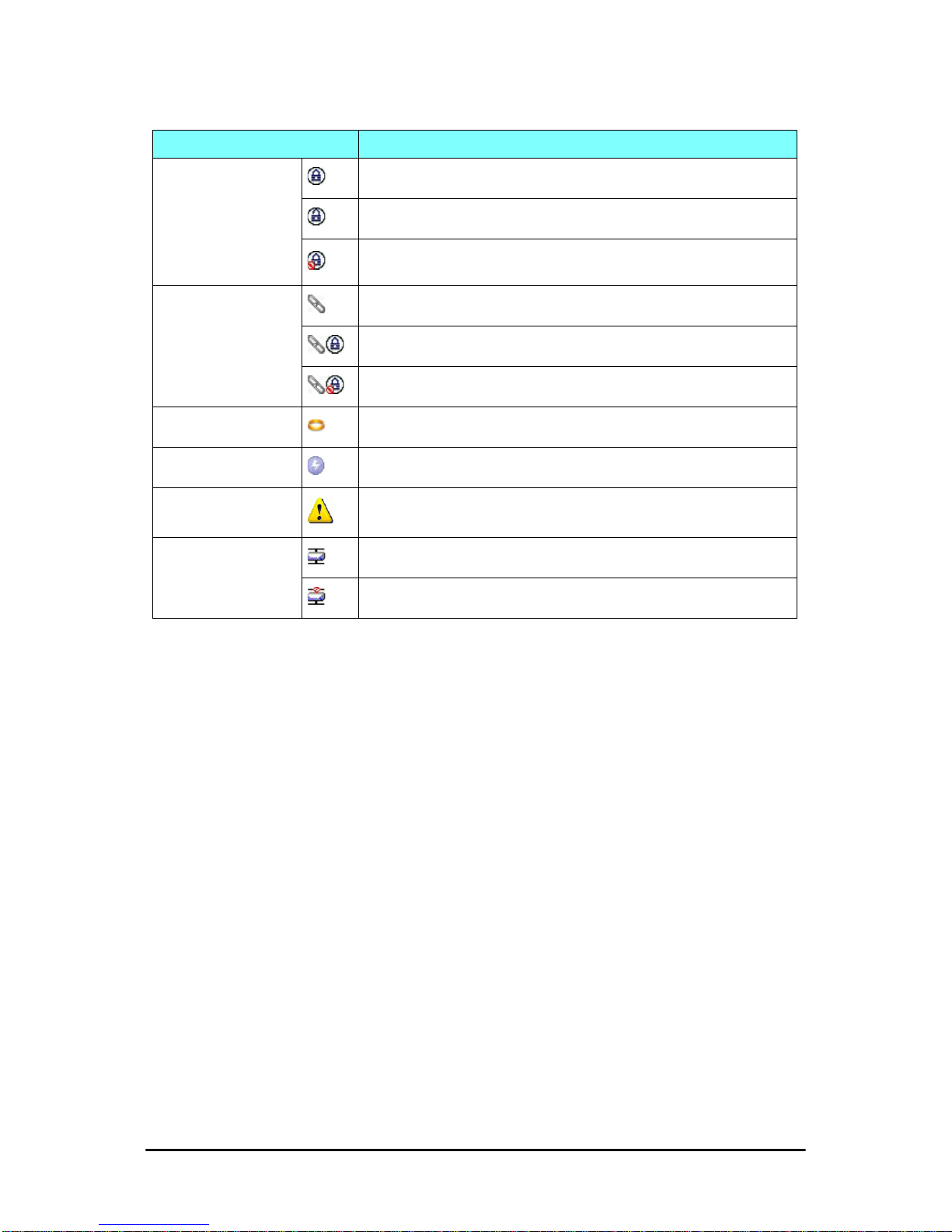
Elements of the FibeAir2000 Manager Main Window Chapter 6
FA4800 User Manual Release 1.9.30 6-8
Encryption indicator
Normally encrypted link
Unencrypted link - lock open
Link password validation failed. The link is encrypted with default keys.
Service and configuration are unavailable. Change the link password.
Link Lock
Link Lock enabled
Link Lock encrypted
Link Lock mismatch
Ethernet Ring Member
DFS in use
Rescue Alarm In the event of an active alarm, opens alarms dialog
TDM Backup (IDU-R)
Backup enabled
Backup disabled
Table 6-3: Status bar indicators (Continued)
Icon or Label Purpose
 Loading...