

Page 1
VGreen® Motor Automation Adapter Kit
Regal Beloit America, Inc.
1325 Heil Quaker Blvd.
LaVergne, TN 37086
Customer Service: 1-800-262-6484
www.RegalBeloit.com
F O R M
C0048E
Revised
December 2018
Installation Manual and User’s Guide
For use with Century® VGreen variable speed motors
• Read and follow all instructions carefully.
• Disconnect and lock out power before installation and maintenance. Working on or near energized equipment could result in severe
injury or death.
TABLE OF CONTENTS
1.0 KIT CONTENTS ....................................................................................................... 1
2.0 INTRODUCTION ...................................................................................................... 2
3.0 OVERVIEW .............................................................................................................. 2
4.0 CONNECTING TO A VGREEN MOTOR ................................................................... 2
5.0 CONNECTING TO AN ALTERNATE POWER SOURCE ........................................... 5
6.0 CONNECTING TO AN AUTOMATION SYSTEM ..................................................... 5
6.1 Using automation system output connectors .................................................. 5
6.2 Using automation system relays ........................................................................ 5
6.2.1 Connecting to input side of relays ............................................................... 5
6.2.2 Connecting to output side of relays ............................................................ 6
6.2.2.1 Output signal powered by automation adapter .................................. 6
6.2.2.2 Output signal powered by alternate power supply ............................. 6
7.0 OPERATING A VGREEN® MOTOR AUTOMATION ADAPTER ................................ 6
7.1 Adjusting motor speed ......................................................................................... 6
8.0 FAULT STATUS ........................................................................................................ 7
9.0 TROUBLESHOOTING GUIDE ................................................................................. 7
10.0 SPECIFICATIONS ..................................................................................................... 7
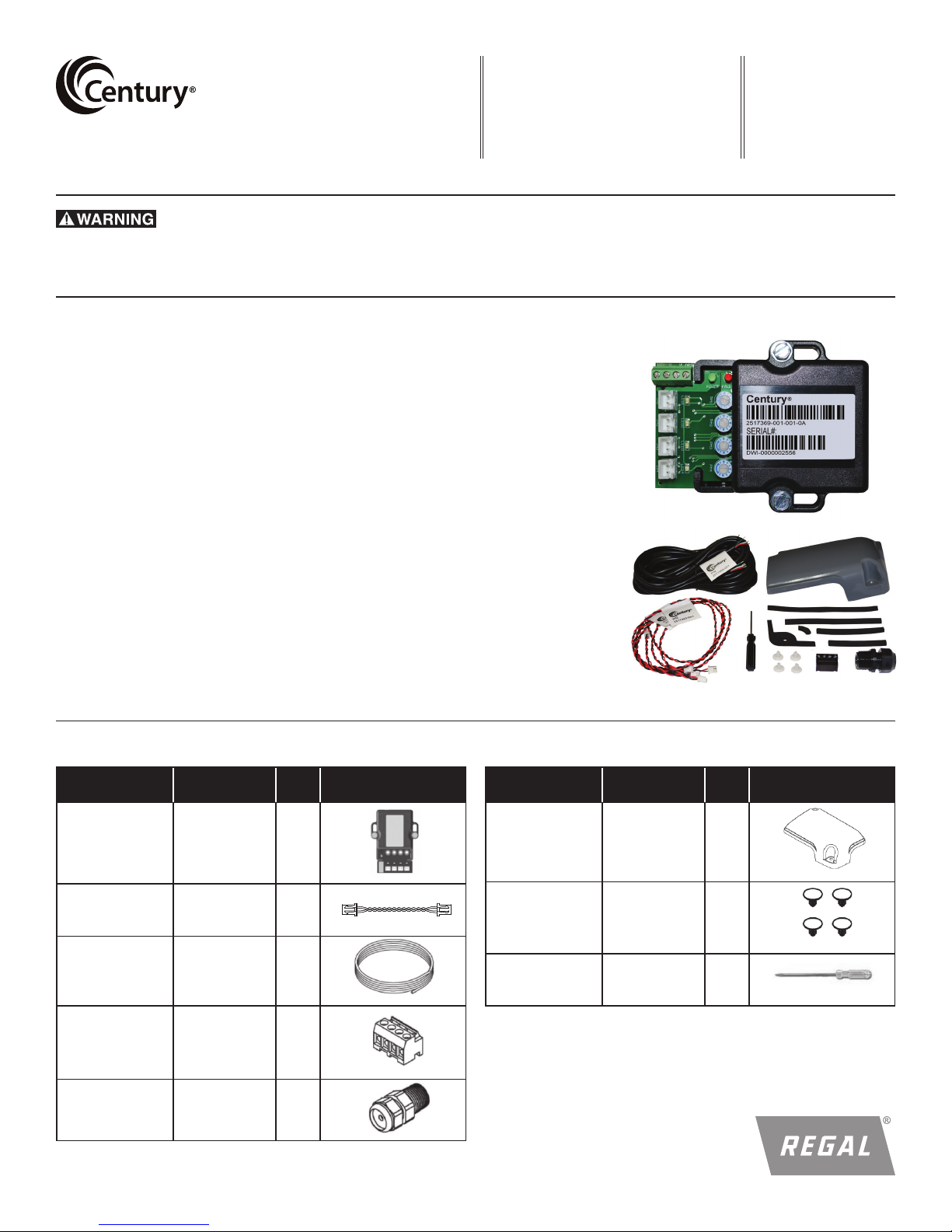
1.0 KIT CONTENTS
PART
Autolmation
Adapter
Digital Input
Cable
Lead Cable 2517465-001 25 FT
RS-485
Connector
Conduit Fitting 2017587-002 1
PART
NUMBER
2517369-001 1
2517463-001 4
2511130-001 1
QTY IMAGE
PART
Terminal Box
Cover Assembly
Plug 2514059-001 4
Screw Driver 2517831-001 1
PART
NUMBER
2513409-001
(Grey)
2513409-002
(Black)
QTY IMAGE
1
1
Page 2
2.0 INTRODUCTION:
The VGreen® Motor Automation Adapter provides the ability to
operate a VGreen motor with a 3rd party automation system such
as the Hayward®* Goldline Pro Logic®*, Pentair®* Easytouch®*,
Jandy®* Aqualink®*, and Intermatic®* controls. This will allow the
user to control and experience the full variable speed capability of
a VGreen product through an existing automation system.
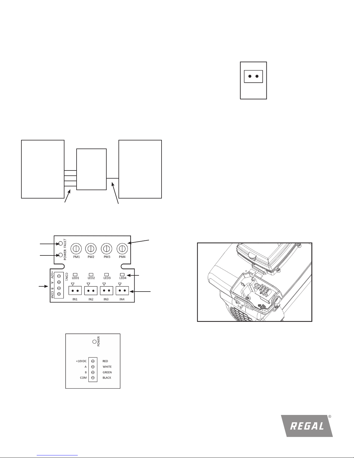
3.0 OVERVIEW:
WARNING! SHOCK HAZARD
Access to the connections referenced in the diagams below
could be in close proximity to mains connections which carry
line voltage capable of causing personal injury or damaging the
equipment if contact is made power should be turned off when
accessing these areas. Failure to take these precautions could
result in serious injury or death.
System:
Automation
System
Automation
IN1-IN4
System Outputs J103
2 Conductor Cable
PN: 2517463-001
VGreen
Motor
Adapter
Figure 1
®
CON1
Adapter control board:
4 Conductor Cable
PN: 2517465-001
VGreen
Motor
®
Digital Input:
IN1, IN2, IN3, IN4: 9-30 VAC/VDC (2mA Typical, 22mA MAX)
Connect to relay coil or valve control of automation system.
PWM IN1 Only: 70-125Hz 5-97 % Duty Cycle
Figure 4
4.0 CONNECTING TO A VGREEN® MOTOR
WARNING! SHOCK HAZARD
The automation adapter must be wired according to the locally
adopted version of the NEC. A licensed, qualified electrician
should complete the wiring for this product. Failure to comply
with this could result in death, serious personal injury or property
damage.
NOTE: Refer to manufacturer’s instructions for wiring on all other
products other than the automation adapter.
The following steps should be followed to connect the automation
adapter to a VGreen® motor.
1. Disconnect all power sources from the motor and wait five
minutes.
2. Remove the terminal box cover from the controller (two
screws).
Fault
LED
Power
LED
Power and
RS-485
Connector
Power / RS-485 Input:
CON1:
Speed
Adjustment
Potentiometer
(4x)
Active Input
LED’s (4x)
Input
Connector
(4x)
Figure 2
Figure 5: Terminal box cover removed
Figure 3
*The following trademarks or trade names are not owned or controlled by Regal Beloit Corporation:
Hayward and Goldline ProLogic are believed to be the trademarks or trade names of Hayward Industrial Products, Inc.
Pentair and Easytouch are believed to be the trademarks or trade names of Pentair Flow Services, AG.
Jandy and Aqualink are believed to be the trademarks or trade names of Zodiac Pool Systems LLC.
Intermatic is believed to be the trademark or trade name of Intermatic Inc.
2
Page 3
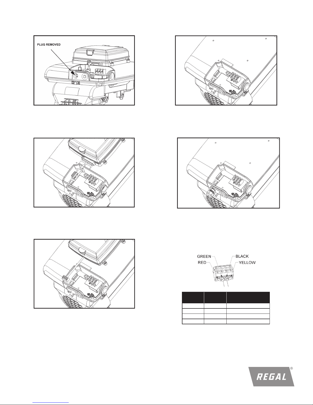
3. Remove the 3/8” conduit hole plug with a 5/16”
allen wrench.
6. Remove the user interface from the controller (four screws).
Figure 6: 3/8” Conduit hole plug removed
4. Remove the plastic wiring cover inside the terminal box
(one screw).
Figure 7: Internal plastic cover removed
5. Disconnect the 4-pin communication connector (J103)
by pulling up on the connector.
Figure 9: User interface and rubber gasket removed
7. Install the conduit fitting (PN: 2017587-002), turning until
snug.
Figure 10: Conduit fitting installed
8. Route the cable (PN: 2517465-001) through the conduit
fitting, and install to the J103 connector (PN: 2511130-001)
on the cable. See the wiring diagram. Tighten the seal nut
on the conduit fitting until snug.
Figure 8: Communication connector disconnected
3
Pin
Wire
Color
Description
J103-1 Red +10V
J103-2 White RS485-A
J103-3 Green RS485-B
J103-4 Black Isolated ground
Figure 11: Communication connection wiring
Page 4

Figure 12: Cable installed
Dip Switches:
Dip switches one and two of the VGreen® motor need to be on in
order for the automation adapter to function.
REFER TO THE VGREEN MOTOR USER MANUAL FOR DIP
SWITCH POSITIONING.
9. Replace the plastic cover inside the terminal box (one
screw).
11. Assemble the new metal terminal box cover (two
screws). Plug the four user interface mounting holes
with the plastic clips (PN: 2514059-001).
Mounting
Holes
(4X)
Figure 15: Terminal box cover and clips installed
Figure 13: Plastic cover installed in terminal box
10. Attach new gaskets to new terminal box cover.
12. Mount the automation adapter inside of the automation
system control box using double sided mounting tape
supplied on the back of the adapter. Place unit so that the
orientation of the input connectors are downward.
NOTE: Automation adapter wiring is all low voltage; choose a
mounting location away from all high voltage wiring.
Automation
Adapter
Digital
Inputs
Low Voltage
Wire
Figure 14: Gasket placement on new terminal box cover
4
HIgh Voltage
Wire
Figure 16: Automation adapter mounted
Page 5

13. Connect the four wires from the motor to the automation
adapter.
VGreen®
Motor
J103
Figure 17: Motor connected to adapter
5.0 CONNECTING TO AN ALTERNATE POWER
SOURCE:
If you choose not to power the automation adapter from the
®
VGreen
adapter can be powered from any 10-14 VDC alternate power
supply.
motor (J103 low voltage power supply), the automation
Alternate
Power Source
Figure 18:
Automation adapter connected to alternate power source
OUTPUTS
(i.e. AUX1)
VGreen®
Motor
Figure 19:
Automation adapter connected to automation system using
the automation system outputs
6.2 USING AUTOMATION SYSTEM RELAYS
6.21 Connecting to input (i.e. low voltage) side of relays
Connect IN1 to Relay 1 or any relay from the automation
system. Repeat this for IN2, IN3, and IN4 using different
automation system relays for each input.
6.0 CONNECTING TO AN AUTOMATION SYSTEM
WARNING! SHOCK HAZARD
Access to the connections referenced in the diagrams
and instructions below could be in close proximity to main
connections which carry line voltage capable of causing personal
injury or damaging the equipment if contact is made. Power
should be turned off when accessing these areas. Failure to take
these precautions could result in serious injury or death.
NOTE: User may use a minimum of 1 and a maximum of 4 inputs
to the automation adapter.
WARNING! SHOCK HAZARD
Failure to connect the automation adapter to the automation
system wighout using correct polarity may result in damage to
the automation adapter and automation system.
6.1 USING AUTOMATION SYSTEM OUTPUT CONNECTORS
Connect IN1 to AUX1 or any output from the automation
system. Repeat this for IN2, IN3, and IN4 using different
automation system outputs for each input.
VGreen®
Motor
Figure 20:
Automation adapter connected to automation system using
the automation system relays
5
Page 6

6.2.2 Connecting to input (i.e. high voltage) side of relays
6.2.2.1 Output signal powered by automation adapter
From the 10V connection of the automation adapter board
(CON1), run a wire to the input on desired relays. Run
the output of the relay to the right pin of an input on the
automation board (IN1-IN4). Connect IN1-IN4 left pin with
COM on CON1 of the automation adapter.
7.0 OPERATING A VGREEN® MOTOR
AUTOMATION ADAPTER
Figure 23: Automation adapter board
7.1 ADJUSTING MOTOR SPEED
The motor speed for each input can be set independently. To do
this, using the screw driver provided, turn the potentiometer
clockwise or counterclockwise. Clockwise increases the speed
and counterclockwise decreases the speed. The speed ranges
from 600-3450 RPM. Do this for each input.
VGreen®
Motor
Figure 21:
Automation adapter connected to automation system using
the automation system relays
6.2.2.2 Output signal powered by alternate source from
an alternate power supply (9-30 VAC/VDC), run a wire from
the positive side of the power source (DC+) to the input on
the desired relays. Run the output of the relay to the right
pin of an input on the automation board (IN1-IN4). Connect
IN1-IN4 left pin with the common (DC-) of the alternate
power source.
When applying a PWM signal to IN1, the speed is based on
the duty cycle. A 97% duty cycle is 3450 RPM and a 5% duty
cycle is 600 RPM. Intermittent speeds can be set by raising or
lowering the duty cycle of the PWM signal.
NOTE: When using a PWM signal as an input for IN1, if the duty
cycle is less than 5%, the automation adapter will not accept
this input. It will be treated as if there is no input being applied.
If the duty cycle is greater than 97%, the automation adapter
will accept this input as a DC voltage or normal input. In this
case the speed of the motor is controlled by the corresponding
potentiometer.
NOTE: If more than one digital input is present, then the
automation adapter will give priority to the highest number digital
input. Therefore IN4 has highest priority followed by IN3, then
IN2, then IN1. To show this, the highest priority input LED is the
only input LED illuminated when two or more inputs are present.
NOTE: When communication between the adapter and the
motor is interrupted or lost, the motor will continue to operate for
approximately 1 minute before stopping.
VGreen®
Motor
Figure 22:
Automation adapter connected to automation system using
the automation system relays
6
Page 7

8.0 FAULT STATUS
Fault LED
Behavior
OFF No error N/A
Flash 1 time No response
Flash 2 times Data error
Flash 3 times CRC error
Flash 4 times Low input voltage
Flash 5 times Motor fault
Flash 6 times Command error
Definition
Check communication
connections (RS-485)
Check power connection and
verify that there is a 10 VDC
input
Refer to your VGreen
motor user manual
9.0 TROUBLESHOOTING GUIDE
Symptom
Power is applied
to the motor, but
power LED is not
illuminated on
the automation
adapter
Possible
Causes
Power supply cables
are loose at the RS-485
connector
Power supply cables are
loose at CON 1 of the
adapter
Motor dip switches1 and
2 are not on
Potential
Solutions
®
Potential
Solutions
Check/tighten the
connections
Check/tighten the
connections
Turn motor dip switches 1
and 2 on
Automation adapter is
damaged
Automation
adapter is presenting a digital
input, but motor
is not running
Fault LED blinked Check fault table
Possible connection loss Check/tighten connections
Automation adapter is
damaged
Replace automation
adapter
Replace automation
adapter
10.0 SPECIFICATIONS
OVERALL RATINGS
Input (CON1) 10-14 VDC (30mA Typical)
Aux inputs (IN1 - IN4) 9-30 VAC/VDC (2mA Typical, 22mA MAX)
- PWM input (IN1 Only) 70-125Hz 5-97 % duty cycle
Ambient conditions
Storage -30°C to 80°C (-22°F to 176°F)
Operating 0°C to 50°C (32°F to 122°F)
Humidity 0-85% Non-condensing
Regal, Century and VGreen are trademarks of Regal Beloit Corporation or one of its affiliated companies.
©2013, 2018 Regal Beloit Corporation, All Rights Reserved. MCIM18021E • Form# C0048E
7
 Loading...