

Page 1

Hobby World Corporation
600
T
gasser conversion
Kit Features:
Lightweight yet extremely strong carbon fiber frames.
Extra large heavy duty clutch system for sustained power transfer.
Plastic injection molded fan cowling for high efficiency engine cooling.
300 mL fuel tank for long engine run time.
5 point engine stabilization system.
Slant gear pinion and main gear provide efficiency and strength.
Heavy duty one-way auto-rotation hub and bearing.
High efficiency push/pull two sided cooling fan.
Heavy duty landing gear.
Exclusively distributed by Century Helicopter Products
© 2011 Hobby World Corporation - All rights reserved.
Version 1.01
Page 2

INTRODUCTION
T600 GASSER CONVERSION
Thank You
Congratulations on the purchase of the newest product that enables the conversion of to gasoline power. This conversion kit will allow
efficient and inexpensive flights with your helicopter.
Warning
This radio controlled model is not a toy! It is a precision machine requiring proper assembly and setup to avoid accidents. It is the
responsibility of the owner to operate this product in a safe manner as it can inflict serious injury otherwise. It is recommended that if
you are in doubt of your abilities, seek assistance from experienced radio control modelers and associations. Keep loose items that can
get entangled in the rotor blades away for the main and tail blades, including loose clothing, hair, or other objects such as pencils and
screwdrivers. Especially keep your hands away from the rotor blades. As manufacturer, we assume no liability for the use of this product.
Flight Guidelines
Please note this checklist is not intended to be a replacement for the content included in this instruction manual. Although it can
be used as a quick start guide, we strongly suggest reading through this manual completely before proceeding.
Always turn the transmitter on first
Allow the gyro, and receiver to arm and initialize properly
Do a pre-flight check making sure all electronics are working and look for any mechanical issues
Fly the model
Land the model
Turn off the engine
Always turn the transmitter off last
General Guidelines
Apply thread lock to all metal to metal thread contact points. Do not apply CA (cyanoacrylate) glue or thread lock to ny-lock nuts (metal nuts
with plastic inserts). Diagrams indicated by bounding boxes for screws, bearings, etc. are illustrated at a 1-to-1 ratio. All other illustrations
are not drawn to scale. Throughout this manual, you will find building tips. Please follow the tips and use common sense when building.
Pre-assembly Information
Various assemblies have been pre-assembled however, only as a reference assembly. Final assembly is up to the user. Installation onto
the particular parts, screws and nuts required for each step are packaged in the same bag as the parts. Be careful when opening each
bag as not to lose any hardware. Care has been taken in filling and packing of each bag however mistakes do happen. If there is a parts
shortage or missing hardware please contact us at:
.launam eht fo snoitces eht ot dnopserroc hcihw ylbmessa fo esae rof deggab era strap tnenopmoc rojam eht lla ,tik eht gninepo nopU
For support, please contact your local dealer/distributor
Page 2
Page 3
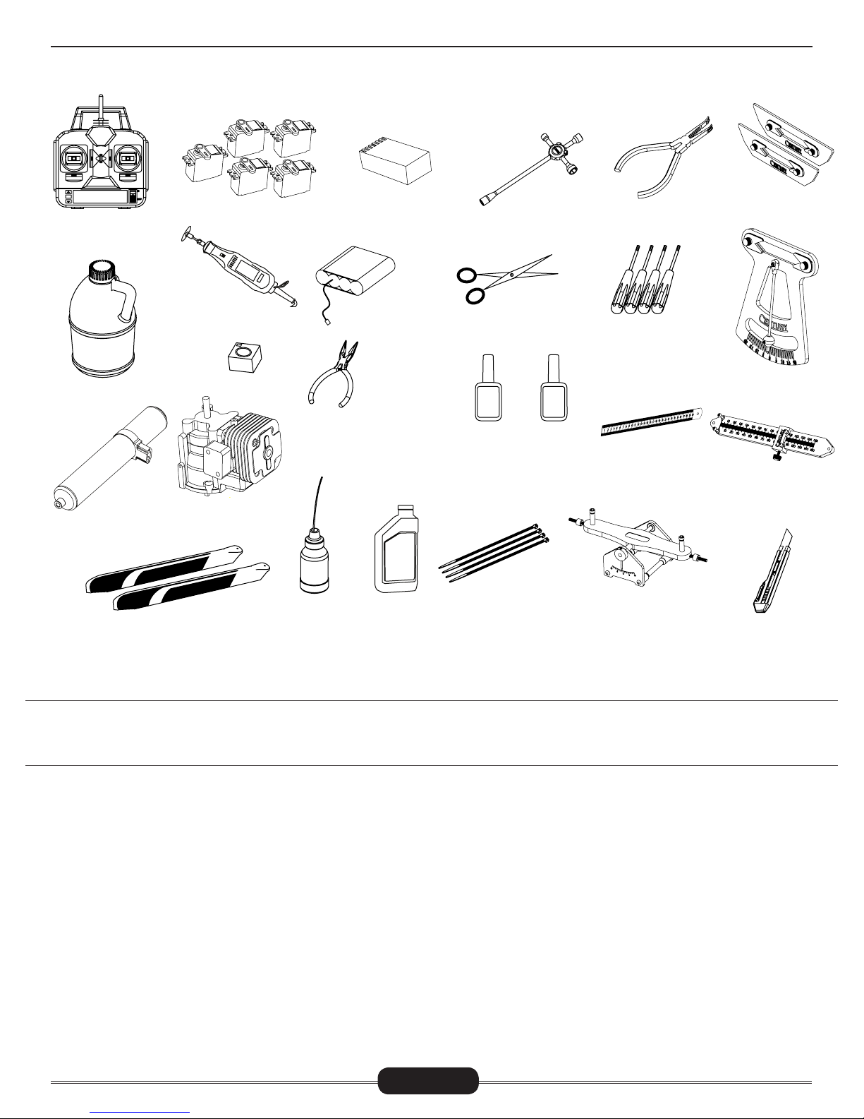
REQUIRED ITEMS
T600 GASSER CONVERSION
6 CHANNEL
CCPM TRANSMITTER
(MINIMUM)
1.000
87 TO 92 OCTANE
GASOLINE
CN3071
TORPEDO hGASSER
TUNED MUFFLER
600mm - 620mm
MAIN ROTOR BLADES
SERVOS X 5
DREMEL TOOL
OR SIMILAR
GYRO
1.000
23CC ZENOAH
GASOLINE ENGINE
NEEDLE NOSE
PLIERS
SYNTHETIC
OIL/GREASE
6 CHANNEL RECEIVER
(MINIMUM)
RECEIVER BATTERY
2-STROKE
MOTOR OIL
CN2031
4-WAY WRENCH
HOBBY SCISSORS
SLOW &
Medium CA
GLUE
ZIP TIES
HEX DRIVERS
1.5, 2.0, 2.5, 3.0, 4.0, 5.0
Medium
(Medium)
THREAD-
LOCK
METRIC RULER OR
SIMILAR MEASURING
ACCURATECH BLADE BAL-
ANCER V.2
CN2034A
BALL LINK PLIERS
CN2017
DEVICE
CN2051
CN2050
PADDLE GAUGE
CN2027
G-FORCE PITCH GAUGE
CN2255
CONTROL ROD
SETUP GAUGE
HOBBY KNIFE
Warranty Period
Hobby World Corporation
ship 30 days from the date of purchase by the Purchaser.
warranties that the Products purchased (the “Product”) will be free from defects in materials and workman-
Limited Warranty
(a) This warranty is limited to the original customer (“Purchaser”) and is not transferable. REPAIR OR REPLACEMENT AS PROVIDED
UNDER WARRANTY IS THE EXCLUSIVE REMEDY OF THE PURCHASER. This warranty covers only those Products purchased from an
authorized Hobby World Corporation dealer. Third party transactions are not covered by this warranty. Proof of purchase is required
for the warranty claims. Further, Hobby World Corporation reserves the right to change or modify this warranty without notice and
disclaims all other warranties, express or implied.
(b) Limitations – HOBBY WORLD CORPORATION MAKES NO WARRANTY OR REPRESENTATION, EXPRESS OR IMPLIED, ABOUT NONINFRINGEMENT, MERCHANTABILITY, OR FITNESS FOR A PARTICULAR PURPOSE OF THE PRODUCT. THE PURCHASER ACKNOLEDGES
THAT THEY ALONE HAVE DETERMINED THAT THE PRODUCT WILL SUITABLY MEET THE REQUIREMENTS OF THE PURCHASER’S
INTENDED USE.
(c) Purchaser Remedy – Hobby World Corporation’s sole obligation hereunder shall be that Hobby World Corporation will, at its option,
(i) repair or (ii) replace, any Products determined by Hobby World Corporation to be defective. In the event of a defect, these are the
Purchaser’s exclusive remedies. Hobby World Corporation reserves the right to inspect any and all equipment involved in a warranty
claim. Repair or replacement decisions are at the sole discretion of Hobby World Corporation. This warranty does not cover damage
due to the improper installation, operation, maintenance, or attempted repair by anyone other than Hobby World Corporation. Return
of any goods by Purchaser must be approved by Hobby World Corporation before shipment.
Page 3
Page 4

AMA RULES & REGULATIONS
T600 GASSER CONVERSION
General
1) I will not fly my model aircraft in sanctioned events, air shows or model flying demonstrations until it has been proven to be airworthy by having been previously, successfully flight tested.
2) I will not fly my model higher than approximately 400 feet within 3 miles of an airport without notifying the airport operator. I will
give right-of-way and avoid flying in the proximity of full-scale aircraft. Where necessary, an observer shall be utilized to supervise flying
to avoid having models fly in the proximity of full-scale aircraft.
3) Where established, I will abide by the safety rules for the flying site I use, and I will not willfully or deliberately fly my models in a
careless, reckless and/or dangerous manner.
4) The maximum takeoff weight of a model is 55 pounds, except models flown under Experimental Aircraft rules.
5) I will not fly my model unless it is identified with my name and address or AMA number on or in the model. (This does not apply to
models while being flown indoors.)
6) I will not operate models with metal-bladed propellers or with gaseous boosts, in which gases other than air enter their internal
combustion engine(s); nor will I operate models with extremely hazardous fuels such as those containing tetranitromethane or hydrazine.
Radio Control
1) I will have completed a successful radio equipment ground range check before the first flight of a new or repaired model.
2) I will not fly my model aircraft in the presence of spectators until I become a qualified flier, unless assisted by an experienced helper.
3) At all flying sites a straight or curved line(s) must be established in front of which all flying takes place with the other side for
spectators. Only personnel involved with flying the aircraft are allowed at or in front of the flight line. Intentional flying behind the flight
line is prohibited.
4) I will operate my model using only radio control frequencies currently allowed by the Federal Communications Commission. (Only
properly licensed Amateurs are authorized to operate equipment on Amateur Band frequencies.)
5) Flying sites separated by three miles or more are considered safe from site-to site interference, even when both sites use the
same frequencies. Any circumstances under three miles separation require a frequency management arrangement, which may be
either an allocation of specific frequencies for each site or testing to determine that freedom from interference exists. Allocation
plans or interference test reports shall be signed by the parties involved and provided to AMA Headquarters. Documents of agreement and reports may exist between
(1) Two or more AMA Chartered Clubs, (2) AMA clubs and individual AMA members not associated with AMA Clubs, or (3) two or
more individual AMA members.
6) For Combat, distance between combat engagement line and spectator line will be 500 feet per cubic inch of engine displacement.
(Example: .40 engine = 200 feet.); electric motors will be based on equivalent combustion engine size. Additional safety requirements
will be per the RC Combat section of the current Competition Regulations.
7) At air shows or model flying demonstrations, a single straight line must be established, one side of which is for flying, with the
other side for spectators.
8) With the exception of events flown under AMA Competition rules, after launch, except for pilots or helpers being used, no powered
model may be flown closer than 25 feet to any person.
9) Under no circumstances may a pilot or other person touch a powered model in flight.
Page 4
Page 5
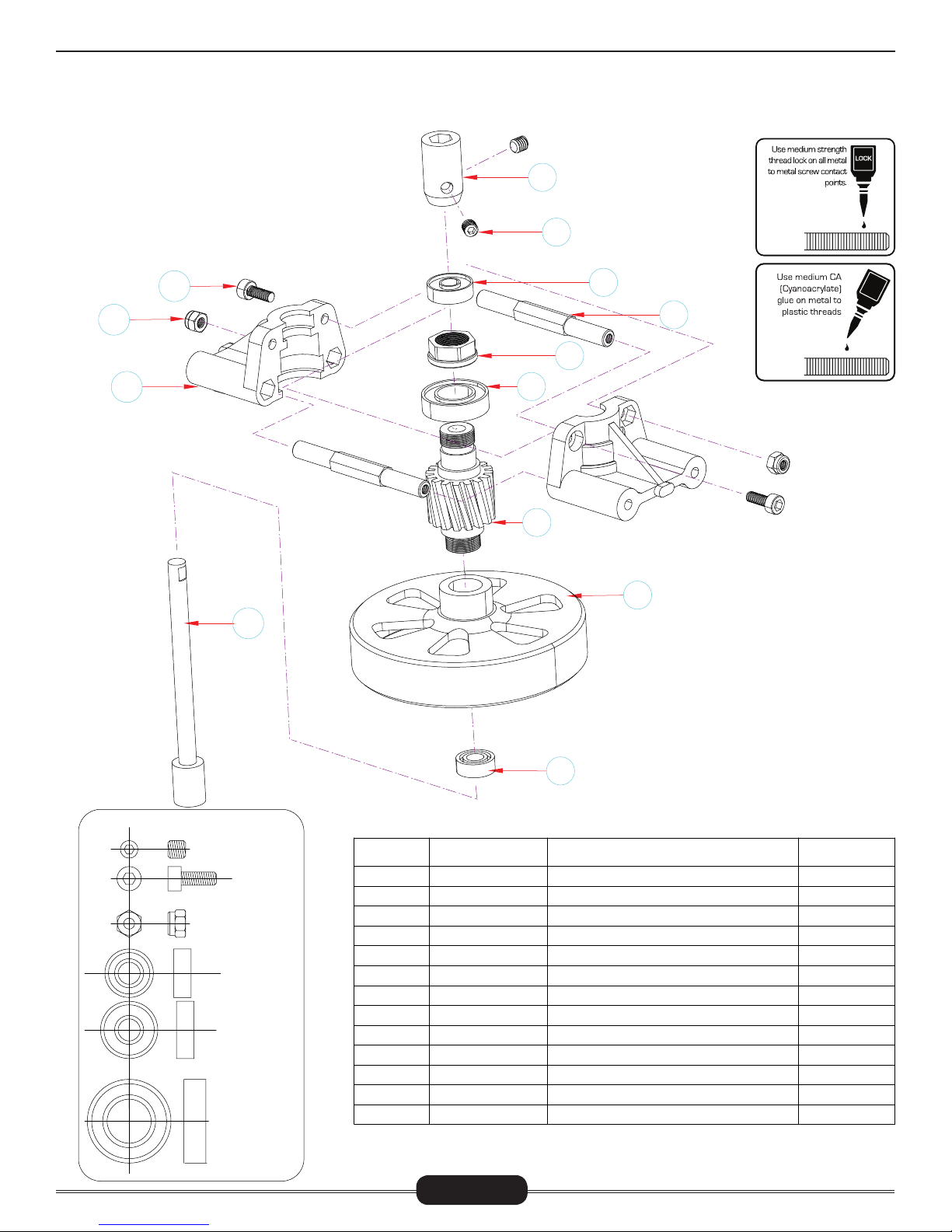
CLUTCH ASSEMBLY
T600 GASSER CONVERSION
Do not open all the bags prior to starting assembly. Open the bags step by step as you go through the instruction manual. The
components are bagged to make assembly easier. The part numbers with an astericks* indicate they are OEM Align part numbers. If you do not have these or similar parts, this conversion kit will not work.
Clean the top of the pinion gear and the inside surfaces of both
the upper and lower bearings inside the clutch shaft bearing
block using alcohol. Apply a small amount of Red threadlock to
the top edge of the clutch gear where it will contact the bearing. Press the bearing block in place, firmly seating the bearing
against the top of the pinion gear.
1
2
12
11
13
10
5
C
A
4
3
6
7
This conversion kit uses the regular starting
shaft and hex coupler to align the clutch to
the clutchbell. Clean both the starting shaft
and the inside race of the bearing inside the
clutchbell and the inside race of the top start-
8
ing shaft bearing. Apply a small amount of
red threadlock positioned just above where
the bottom clutchbell bearing will sit on the
starting shaft. Slide the starting shaft up
through the bearing blocks. Apply a small
amount of medium threadlock to the top of
the starting shaft and slide the hex coupler
in place aligning the flat spot with one of the
holes. Apply medium threadlock to the two
M4x4 set screws and tighten in place.
9
CNM4x4SS
CNM3x8CS
M3 CNM3LOCK
CNBB511
CNBB513
CNBB1019
No.
1
2
3
4
5
6
7
8
9
10
11
12
13
Part #
HW6002
CNM4X4SS
HN6007*
HN6004*
CNBB513
CNBB1019
HW6043B6
HW6013G3
CNBB511
HW6006G3
HN6007*
CNM3LOCK
CNM3X8CS
Page 5
Description
Hex Starter Adapter( 六角启动头)
M4x4 Set Screw( 无头内六角螺丝 )
Clutch Nut(离合器齿轮螺母 )
L=49mm Hex Mounting Bolt( 六角铝柱 )
5X13X4Bearing( 轴承)
10X19X5Bearing( 轴承)
16T Clutch Gear(16 齿离合器齿轮 )
Clutch Bell Assembly 67mm( 离合器罩)
5X11X4Bearing( 轴承)
Start Shaft(启动轴 )
Clutch Bearing Block( 离合器轴承座 )
M3 Locknut(M3防松螺母 )
M3X8 Cap Screw( 杯头螺丝 )
Qty
1
2
1
2
1
1
1
1
1
1
2
2
2
Page 6
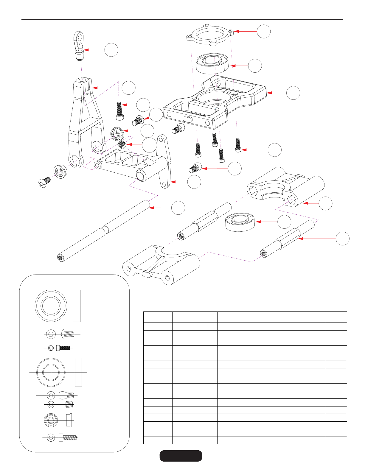
BEARING BLOCKS & ELEVATOR ARM
16
T600 GASSER CONVERSION
1
2
15
14
12
11
13
8
3
4
10
9
5
6
7
CNBB1019
CNM3x6BHCS
CNM2X6CS
CNBB0917
球头Ø4.75X8.68
CNM4x4SS
CNBB37F
CNM2.5x8CS
No.
1
2
3
4
5
6
7
8
9
10
11
12
13
14
15
16
Part #
H60154*
CNBB1019
H60154*
CNM2X6CS
HN6011*
CNBB0917
HN6004*
H60220*
H60129*
H60224*
CNM4X4SS
CNBB0730F
CNM3X6BHCS
CNM2.5X8CS
H60128*
H60128*
Page 6
Description
Metal Main Shaft Clamp Ring( 金属主轴固定盖)
10X19X5Bearing( 轴承)
Metal Bearing Block( 金属主轴固定座)
M2X6 Cup Screw( 杯头螺丝)
Plastic Bearing Block( 塑料主轴固定座)
9X17X4 Bearing( 轴承)
L=49mm Hex Mounting Bolt( 六角铝柱)
Control Shaft( 连动秆)
Elevator Lever( 升降连动控制臂)
Linkage Ball A(M3x4)( 球头A(M3X4))Ø4.75X8.68
M4x4 Set Screw( 无头内六角螺丝)
3X7X3 Bearing( 带边轴承)
M3X6 Button Head Screw( 圆头螺丝)
M2.5X8 Cap Screw( 杯头螺丝)
Elevator Arm( 升降控制臂)
Elevator Ball Link( 升降臂连杆头)
Qty
2
2
2
8
2
1
2
1
1
2
1
2
2
1
1
1
Page 7
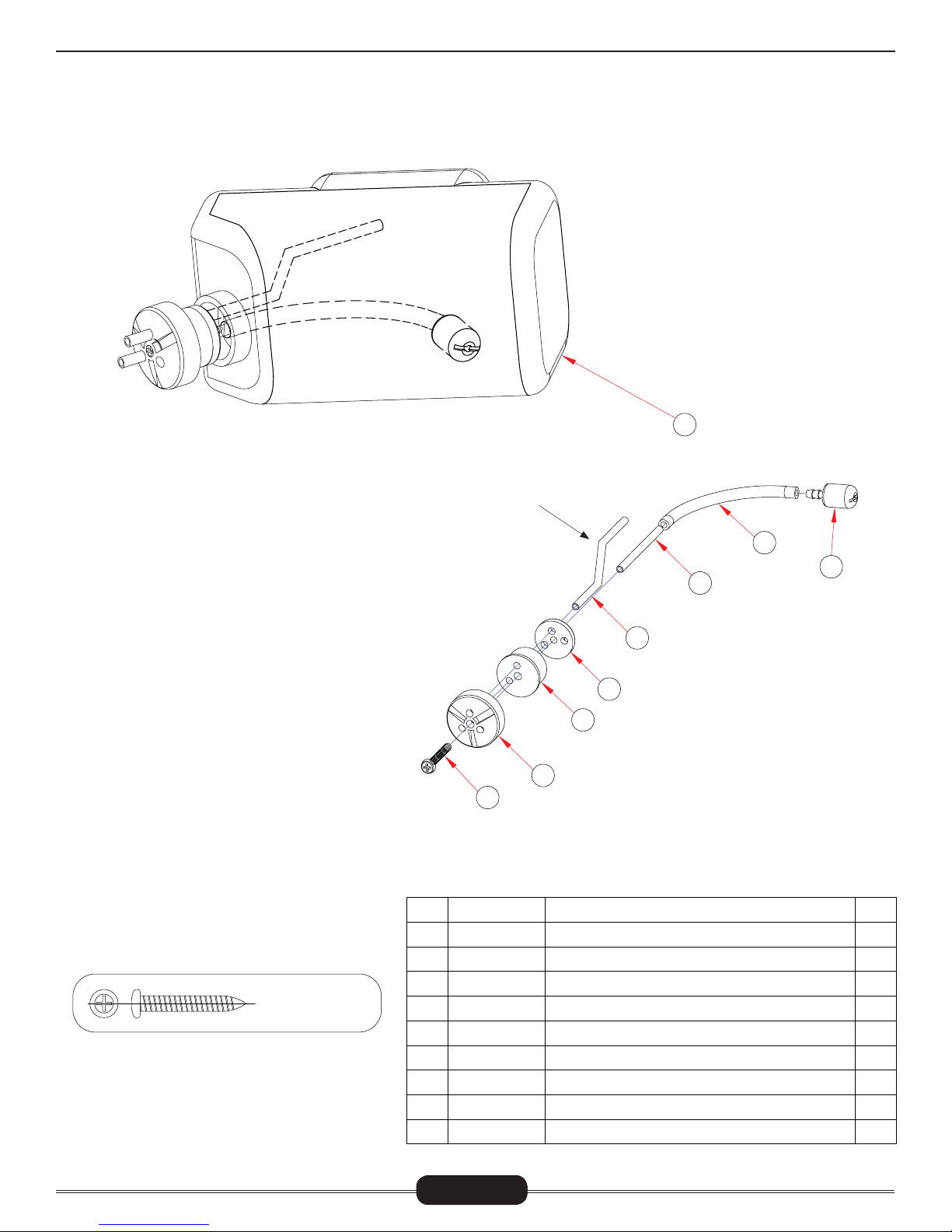
FUEL TANK ASSEMBLY
T600 GASSER CONVERSION
9
Pay close attention when assembling the fuel tank.
The vent tube must be bent and facing upwards when
installed into the rubber stopper. There are 3 holes
on the rubber stopper but notice only 2 are through
holes. Cut the fuel line and attach the clunk to the
line. Then attach the fuel line to the short brass tube.
When cutting the fuel line, make sure you have enough
slack in the fuel line so the clunk can reach all corners
of the fuel tank. After installing the shorter brass tube
with the fuel line, install the vent tube. Make sure the
vent tube is positioned to point upwards in the fuel
tank. Once you have everything positioned, slowly turn
the M3.5x24 Phillips screw so that you barely grab
the end of the small cap (#4). Once you insert the
fuel tubing assembly into the tank, it will be very difficult to get this small cap out if you happen to drop
it within the fuel tank. Making sure you still have the
small cap (#4) attached to the fuel tubing assembly,
push the fuel tubing assembly into the tank and start
tightening the Phillips screw. This will pull the small
cap (#4) closer to the large cap (#2) and expand the
rubber stopper. Once tightened, gently tug on the assembly to make sure it is properly installed. It should
not come out of the fuel tank.
Bend one of the longer
brass tubes into this
shape. This will be the
vent tube.
7
8
6
5
4
3
2
1
CNM3.5x24ST
No.
1
2
3
4
5
6
7
8
9
Part #
HI3138B
HI3138B
HI3138B
HI3138B
HI3138B
HI3138B
HI3138B
HI3138B
HI6139
Page 7
Description
Tapping Screw( 十字紧固螺丝)M3.5x24
Large Cap(油箱盖)
Rubber Stopper( 油箱塞)
Small Cap(油箱塞固定座)
Long Tube-straight( 长直铜油管)
Pickup Tube-straight(短直铜油管)
Plastic Tubing( 塑胶油管)
Fuel Tank Set( 吸油嘴)
Fuel Tank(油箱)
Qty
1
1
1
1
1
1
1
1
1
Page 8

SIDE FRAMES ASSEMBLY
14
10
15
13
12
11
21
17
18
16
8
9
19
20
T600 GASSER CONVERSION
1
2
3
4
5
6
7
No.
1
2
3
4
5
6
7
8
9
10
11
12
13
14
15
16
17
18
19
20
21
Part #
CNM3X12BHCS
CNM3X4.8FW
H60224*
HN6038*
HN6038*
CNBB0630
HN6019*
HI6116T6
HN6015B*
HI6119
CNBB0510
CNM5X7FW
CNM5X7FW
H6024*
CNBB0950
H60027-1-00*
CNM3X5.5FW
CNM3X6CS
CNM3X8FW
CNM3X8BHCS
HI6139B
Description
M3X12 Button Head Screw( 圆头螺丝)
Ø3xØ4.8x0.3 Flat Washer( 平面垫片)
Linkage Ball A(M3x4)( 球头A(M3X4))Ø4.75X8.68
Ø3xØ4.4x3 Collar( 尾控制臂铝套)
Tail Control Arm( 尾控制臂)
3X6X2.5 Bearing( 轴承)
Frame Mounting Block(机身固定块)
Main Frames (R/L)( 左右主体侧板)
M3X8 Button Head Collar Screw( 半圆头轴套螺丝)
Frame Bearing( 侧板轴承座)
5X10X4 Bearing( 轴承)
Ø5xØ7x0.2 Flat Washer( 平面垫片)
Ø5xØ7x0.5 Flat Washer( 平面垫片)
Linkage Ball A(M3x4)( 球头A(M3X4))Ø4.75X8.68
5X9X3 Bearing( 轴承)
Metal Aileron Lever( 金属左右控制摇臂)
Ø3xØ5.5x0.3 Flat Washer( 平面垫片)
M3X6 Cup Screw( 杯头螺丝)
Ø3xØ8x2 M3 Specialty Washer( M3特殊垫片)
M3X8 Button Head Screw( 圆头螺丝)
Fuel Tank Guard( 油箱垫圈)
Qty
1
2
2
1
1
2
1
2
16
2
2
2
2
6
4
2
2
2
2
2
2
CNM3x12BHCS
Ø3xØ4.8x0.3
球头Ø4.75X8.68
Ø3xØ4.4x3
CNBB0630
CNM3x8BHCS
CNBB0510
M3X8 Collar Screw
Ø5xØ7x0.2
Ø5xØ7x0.5
CNBB0950
Ø3xØ5.5x0.3
CNM3x6CS
Ø3xØ8x2
Page 8
Page 9

ELECTRONICS TRAYS
T600 GASSER CONVERSION
1
2
10
11
9
8
3
4
C
A
7
5
6
2
CNM3x8BHCS
Ø3xØ8x2
CNM3x14CS
CNM2.5x6FHCS
No.
1
2
3
4
5
6
7
8
9
10
11
Part #
HN6051*
HN6104*
CNM3X8FW
CNM3X8BHCS
HN6016*
HN6016*
CNM3X14CS
CNM2.5x6FHCS
HW6113T6A
HW6113T6
HN6051*
Page 9
Description
Gyro Mount(陀螺仪固定座)
L=54mm Frame Mounting Bolt( 机身铝柱)
Ø3xØ8x2 M3 Specialty Washer( M3特殊垫片)
M3X8 Button Head Screw(圆头螺丝)
Ø3xØ5x7.3 Canopy Support( 机头罩支撑柱)
Canopy Spacer( 机头罩支撑垫圈)
M3X14 Cap Screw( 杯头螺丝)
M2.5x6 Flush Head Cap Screws( 斜头内六角螺丝)
Electronics Plate(电子板)
L=54mm Frame Support Bar(带平面铝柱)
3x8 Phillips Self Tapping Screw
Qty
1
2
6
6
2
2
2
4
1
2
2
Page 10

ENGINE ASSEMBLY
1
T600 GASSER CONVERSION
6.5x13x18 x13x0.5
2
7
18
19
17
4
9
10
5
6
8
3
11
12
13
14
15
CNM6x16CS
6.5x13x1
CNM2.5x8CS
CNM4x10FHCS
CNM3x6FHCS
CNLR1018
CNM3x4SS
CNM2.5x16CS
CNM3x8BHCS
Build the fan by placing Medium threadlock into the threaded holes on the
fan hub (#6). Attach the fan to the hub as shown and install the M3x6
flush head cap screws making sure the screws fall into the beveled hole
on the fan.
No.
1
2
3
4
5
6
7
8
9
10
11
12
13
14
15
16
17
18
19
20
Part #
CNBB1014A
HW6011G3
HI6020B
CNM6x16CS
CNM6.5x13FW
HI6012
CNM2.5x8CS
HI6011
CNM3x6FHCS
CNM5x10FHCS
CNLR1018
HW6192B
CNM3x4SS
Z231
CNM2.5x8CS
CNM2.5x16CS
HW6116T6
HW6118H3
CNM3x8BHCS
HW6192
Description
Clutch One Way Bearing (10mm)(单向轴承)
Clutch Shoe 59mm ( 离合器)
Plastic Cooling Shroud( 风扇罩)
Cap Screw(杯头内六角螺丝)M6x16
Washer(垫片)6.5x13x1
Cooling Fan Hub ( 风扇座)
Cap Screw(杯头内六角螺丝)M2.5x8
Two Way Cooling Fan( 风扇)
Flush Head Cap Screws( 斜头内六角螺丝)M3x6
M5X10 Flush Head Cap Screws( 斜头内六角螺丝)
Ultra Short Steel Ball( 球头螺丝)
Carburetor Arm( 化油器控制臂)
Set Screw(无头内六角螺丝)M3X4
Engine(引擎)
Cap Screw(杯头内六角螺丝)M2.5x8
Cap Screw(杯头内六角螺丝)M2.5x16
L=54mm Cooling Shroud Plate Support Bar (铝柱)
Cooling Shroud Mount Plate( 挡风板)
M3x8 Button Head Cap Screw( 圆头内六角螺丝)
8x13x0.5 Spacer
Qty
1
1
1
1
1
1
1
1
5
4
1
1
1
1
2
1
1
1
2
4
When tightening the M6x16 bolt, you can use a piston
locking tool made for gasoline engines or you can remove the spark plug and stuff nylon rope into the piston hole. This will allow you to torque the bolt without
the engine spinning. NEVER grab the bottom of the
crank shaft where the starter attaches and tighten
the bolt holding fan/clutch hub.
16
20
Once you tighten the M3X10 Flush Head Cap Screws (#10), the Cooling
Shroud Mounting Plate (#18) should be snug and not move. If it can
still shift or moves, then install the 8x13x0.5 spacers (#20). The reason
for this is the chamfer depth found on some Zenoah engines are not
consistent with others, therefore some engines will require the spacers
and some will not.
Venturi style intake does not
come with the engine.
Page 10
Page 11

LANDING FRAME STRUCTURE
C
A
13
12
T600 GASSER CONVERSION
When installing the engine assembly to
the frames, do not tighten one side all
the way leaving the other side completely loose. Tighten the M4x20 bolts on
either side of the frames evenly moving
from one side to the other. Make sure
to apply medium threadlock to these
bolts prior to installation. After you have
installed the left and right M4x20 bolts,
install the front engine block making sure
to use medium threadlock on the M4x20
1
Install the landing skids onto the landing struts one
side at a time. After installing the landing skids, position, the landing struts on the skids so that they match
up with the mounting positions on the frames. Place
the washers onto the M3x16 cap screws and then
apply medium threadlock. Install the screws through
3
the landing struts and tighten onto the frames. Turn
the landing skids so that the curve towards the front
is facing straight up. Install the four M3x4 set screws
4
to lock the skids into place. Do not tighten these too
much as you can crack the plastic struts. Lastly, install the landing skid stoppers.
5
6
bolt holding the engine’s head in place.
2
CNM3x7FW
CNM2.5x8CS
CNM4x10FW
CNM3x4SS
CNM4x20CS
CNM3x18CS
No.
1
2
3
4
5
6
7
8
9
10
11
12
13
Part #
HW6117G3A
CNM4x20CS
HW6117G30
CNM3x7FW
CNM2.5x8CS
HI6122D
CNM3x4SS
HW3123B
CNM3x7FW
CNM3x18CS
HW3123A
CNM4x20CS
CNM4x10FW
9
10
7
8
Description
Front Engine Mounting Block ( 引擎固定块)
M4X20 Cap Screw( 杯头内六角螺丝)
Landing Gear Frame( 引擎座底板)
3x7x1 Washer( 垫片)
M2.5x8 Cap Screw( 杯头内六角螺丝)
Plastic Struts( 脚架)
M3x4 Set Screw( 无头内六角螺丝)
Aluminum Skids with Caps ( 脚架弯管)
3X7X1 Washer( 垫片)
M3x18 Cap Screw( 杯头内六角螺丝)
Skid End Caps(脚架塞)
M4X20 Cap Screw( 杯头内六角螺丝)
4X10X1 Washer( 垫片)
11
Qty
1
1
1
2
2
2
4
2
4
4
4
2
4
Page 11
Page 12

FRAME REINFORCEMENTS
T600 GASSER CONVERSION
1
2
3
4
5
CNM3x12BHCS
CNM3x10BHCS
Ø3xØ8x2
Ø3xØ5x4
No.
1
2
3
4
5
6
7
8
9
10
7
10
Part #
HI6116TFS
HI6031T6
HI6116TFS
CNM3X8FW
CNM3X10BHCS
CNM3X10BHCS
CNM3X12BHCS
HW6117TS
CNM3X10BHCS
HI6116TRS
8
9
Description
Front Frame Reinforcement Plate (Right) (右机身前侧板补强板)
L=54mm Frame Mounting Bolt( 机身铝柱)
Front Frame Reinforcement Plate (Left) (左机身前侧板补强板)
Ø3xØ8x2 M3 Specialty Washer( M3特殊垫片)
M3X10 Button Head Screw( 圆头螺丝)
M3X10 Button Head Screw( 圆头螺丝)
M3X12 Button Head Screw( 圆头螺丝)
Ø3xØ5x4Aluminum Sleeve( 铝套)
M3X10 Button Head Screw( 圆头螺丝)
Rear Frame Reinforcement Plates (机身后侧板补强板)
6
Qty
1
1
1
8
2
4
2
2
2
2
Page 12
Page 13

RECEIVER & CANOPY MOUNT
T600 GASSER CONVERSION
C
A
10
2
1
3
4
5
2
9
6
7
8
No.
1
2
CNM3x8BHCS
Ø3xØ8x2
CNM2.5x8CS
Ø3xØ5x3
CNM3x10T
CNM3x10BHCS
3
4
5
6
7
8
9
9
Part #
HN6024*
CNM3X8FW
CNM3x10T
CNM3x10T
CNM2.5x8CS
HI6118T6S
HI6118T
HW6205
CNM3X10BHCS
CNM3X8BHCS
Description
Receiver Mount ( 接受机座)
Ø3xØ8x2 M3 Specialty Washer( M3特殊垫片)
M3X10 Socket Button Head Self Tapping Screw(半圆头内六角自攻螺丝)
M3X10 Socket Button Head Self Tapping Screw(半圆头内六角自攻螺丝)
M2.5x8 Cap Screw( 杯头内六角螺丝)
Head Fixed Plate( 机头固定板)
L=54mm Aluminum Column( 带平面铝柱)
3X5X3 Bacer( 铁套)
M3X10 Button Head Screw( 圆头螺丝)
M3X8 Button Head Screw( 圆头螺丝)
Page 13
Qty
1
8
2
2
2
1
1
2
2
2
Page 14

TAIL TRANSMISSION ASSEMBLY
T600 GASSER CONVERSION
3
10
1
2
6
8
4
5
CNBB0490
M3 CNM3LOCK
9
7
No.
1
2
3
4
5
6
7
8
9
10
Part #
HN6030-1*
HN6030-1*
CNBB0490
H60121*
H60121*
H60121*
CNM3LOCK
CNBB1218
HN6090*
CNM3x12CS
Description
Tail Boom Mount(Left) ( 左尾管固定座 )
L=54mm Hexagonal Bolt( 六角铝柱)
4X9X4 Bearing ( 4x9x4轴承 )
Front Drive Gear Assembly( 尾传动导输出轴组)
Tail Boom Mount(Right) ( 右尾管固定座)
Front Umbrella Gear( 前轴传伞齿轮)
M3 Locknut(M3防松螺母)
12X18X4 Bearing (
Tail Boom (尾管
M3x12 Cap Screw( 杯头内六角螺丝)
12x18x4轴承)
)
Qty
1
6
2
1
1
1
4
2
1
4
CNM3x12CS
Page 14
Page 15

TAILBOOM & SUPPORTS
6
T600 GASSER CONVERSION
1
2
Ø3xØ8x2
Ø3xØ5x4
5
4
3
CNM3x18CS
No.
1
2
3
4
5
6
Part #
CNM3x12T
CNM3X8FW
CNM3x18CS
H60052*
H60052*
HN6104*
Description
M3X12 Socket Button Head Self Tapping Screw( 半圆头内六角自攻螺丝)
Ø3xØ8x2 M3 Specialty Washer( M3特殊垫片)
M3x18 Cap Screw( 杯头内六角螺丝)
Tail Boom Brace( 尾管支撑架)
Ø3xØ5x4Aluminum Sleeve( 铝套)
L=54mm Frame Mounting Bolt( 机身铝柱)
Page 15
Qty
6
14
2
2
2
1
Page 16

MAIN GEAR ASSEMBLY
Drop some medium threadlock into the
six holes on the main gear case. Then
use the M3x8 button head cap screws
and install through the main gear case.
Make sure to use threadlock sparingly
as to not get excess threadlock onto
the plastic gear.
If in the future your one-way bearing or
sleeve is worn or damaged, it is highly
recommended to replace the sleeve and
one-way bearing hub at the same time.
T600 GASSER CONVERSION
1
2
DIRECTION OF
FREE SPIN
3
For the roller bearings, we recommend a very light oil. The oil MUSTNOT attack/break down plastic as
this could damage the cage in the
one-way bearing. Prior to applying oil,
make sure to clean the roller bearings with a cotton swab making sure
there is no debris in the bearings.
CNM3x8BHCS
18x24x16
4
Shorter side of protrusion on one-way hub
should be facing up going into the gear.
5
6
7
15x24x2
No.
1
HW6057T6
CNM3X8BHCS
2
3
HI6057T6
4
CNBB1824A
5
HW6057T6H
CNM15X24FW
6
7
H60020A*
Page 16
Part #
Description
Main Shaft Auto Sleeve( 主齿轮铁套)
M3X8 Button Head Screw( 圆头螺丝)
103T Main Gear( 103齿齿轮)
18x24x16 One-way Bearing( 单向轴承)
Main Gear Case( 主齿中心座)
15x24x2 Flat Washer( 铜平面垫片)
Tail Drive Gear (副齿轮)
Qty
1
6
1
1
1
1
1
Page 17

MAIN SHAFT TO MAIN GEAR ASSEMBLY
T600 GASSER CONVERSION
6
5
4
3
10x13x4
CNM4x4SS
M3 CNM3LOCK
CNM3x20CS
1
2
No.
1
2
3
4
5
6
Part #
CNM3x20CS
CNM3LOCK
HW6057T6S1
H60159*
H60159*
CNM4X4SS
Description
M3x20 Cap Screw( 杯头内六角螺丝)
M3 Locknut(M3防松螺母)
10x13x4 Brass Sleeve( 铜套)
Main Shaft(主轴 )
Lock Collar( 主轴固定块)
M4x4 Set Screw( 无头内六角螺丝)
Qty
1
1
1
1
1
2
Page 17
Page 18

SERVO INSTALLATION
T600 GASSER CONVERSION
1
2
3
4
5
6
10
7
9
8
CNM2NUT
CNM3x6ST
CNM2.3x12ST
CNM2x8PH
No.
1
2
3
4
5
6
7
8
9
10
Part #
CNM2NUT
CNM3x6ST
CNM2.3x12ST
HI3205A
H60089*
NOT INCLUDED
CNM2x8PH
HI6205B
NOT INCLUDED
NOT INCLUDED
Description
M2 Nut(M2螺母)
M3x6 Self Tapping Screw(尖尾自攻螺丝)
M2.3x12 Self Tapping Screw( 尖尾自攻螺丝)
Servo Mounting Plate(伺服机固定板)
Linkage Ball A(M2x3.5)(球头A)Ø4.75X8.18
Servo(伺服机)
Phillips Screw(十字螺丝)M2x8
Servo Mount 3 Hole Tabs (伺服机固定座)
Short Servo Arm( 短伺服机摆臂)
Long Servo Arm( 长伺服机摆臂)
Qty
8
5
10
5
8
5
10
10
2
3
Page 18
Page 19

PUSHROD MEASUREMENTS
T600 GASSER CONVERSION
HEL PFUL TOOL
4
1
2
3
5
6
PART# CN2255: CONTROL ROD SETUP GAUGE
21
32
50
31,5
39,5
60,5
51
61
80
80
90
109
3
4
1
No.
1
2
3
4
5
6
6
Part #
HN6099*
HN6052*
HN6099*
HN6099*
HN6099*
HN6099*
Description
L=61mm Linkage Rod(连杆)
Ball Link(连杆头)
L=32mm Linkage Rod(连杆)
L=39.5mm Linkage Rod( 连杆)
L=197mm Linkage Rod( 连杆)
L=90mm Linkage Rod(连杆)
Qty
4
20
2
2
1
1
5
187
197
216
Page 19
Page 20

MUFFLER & ESSENTIALS
T600 GASSER CONVERSION
The muffler is not an included item. It is an optional item that
offers better performance but the stock can muffler from the
engine can be used.
9
8
1
7
10
6
2
3
4
5
CNM5x20CS
CNM3x4SS
No.
1
2
3
4
5
6
7
8
9
10
Page 20
Part #
CN3071
CN3071
CN3071
CNM3x4SS
NOT INCLUDED
NOT INCLUDED
NOT INCLUDED
NOT INCLUDED
NOT INCLUDED
NOT INCLUDED
Description
M5X20 Cap Screw(杯头内六角螺丝)
M5x8 Spring Washer
Torpedo Slim V2 Muffler( 排气管 )
M3x4 Set Screw( 无头内六角螺丝)
Battery(电池)
Receiver( 接受机)
Hook & Loop Strap(束带 )
Anti-vibration Pad (防震垫 )
Gyro (陀螺仪)
Tubing( 油管)
(弹簧垫片
)
Qty
2
2
1
2
1
1
2
1
1
2
Page 21

MOUNTING CANOPY
1
T600 GASSER CONVERSION
3
2
5
4
Congratulations on finishing the build of the gasser conversion for your T600. Please follow your instruction
manual on setting up your transmitter and gyro systems. Also it is very important that you follow the instructions included with the Zenoah G23 engine for the break in process and finally tuning the engine. If the steps
are not followed your engine will not perform at it’s optimum levels.
CNM3x8BHCS
No.
1
2
3
4
5
Part #
H60092*
CNM3X8BHCS
CN2210A
ORIGINAL ITEM
HN6088
Page 21
Description
Canopy Standoff( 机头固定铝柱)
M3X8 Button Head Screw( 圆头螺丝)
Canopy Grommets(橡皮环)
Canopy(机头)
Canopy Mount( 机头固定座)
Qty
2
2
2
1
1
Page 22

PERSONAL BUILD NOTES
T600 GASSER CONVERSION
Page 22
 Loading...