

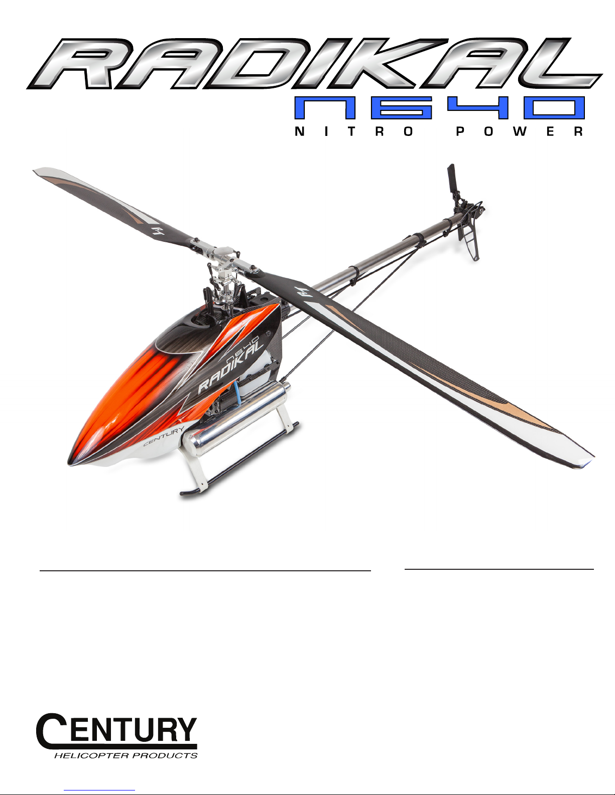
Century Radikal N640 Instruction Manual
Kit Features: Specifications:
8.58 :1 Main gear ratio
4.5:1 Tail gear ratio
Engineered for OS 55/YS56 motors or compatible
Carbon fiber frames for ultra-rigid and compact design
Push/Pull CCPM control system
Triple bearing supported 10mm hardened main shaft
120 degree dual race ball bearing metal swashplate
Stainless steel damper mounted bearing torque tube for high efficiency
Dual race ball bearing with thrust bearing supported tail blade grips
© 2012 Century Helicopter Products - All rights reserved.
Main Rotor Blade Diameter: 57.3 in /
145.5 cm (640 mm Blades)
Tail Rotor Blade Diameter: 10.25 in /
26.0 cm (92 mm Blades)
Length: 49 in / 124.50 cm
Height: 13.7 in / 34.80 cm
Width: 4.5 in / 11.45 cm
Version 1.00
INTRODUCTION
Radikal N640
Thank You
Thank you for purchasing this new class of helicopters. By incorporating the use of blade sizes up to 640mm allowing 700 class flight
characteristics in a smaller, you’ve made the right choice by going for an economical yet extremely high performance helicopter.
Warning!
This R/C helicopter is not a toy! It is a precision machine requiring proper assembly and setup to avoid accidents. It is the responsibility of
the owner to operate this product in a safe manner as it can inflict serious injury otherwise. It is important for the user/pilot to be responsible for the damage the model is capable of inflicting on one’s self and others around the model during its operation. Century Helicopter
Products, affiliated individuals, and shops/sellers hold no accountability for the operation or use of this model. It is recommended that
if you are in doubt of your abilities; seek assistance from experienced radio control modelers and associations. Although the helicopter
is considered small in size, you must be very cautious during the operation of the model as serious damage, injury, or death can occur.
Flight Checklist
Make sure your transmitter battery is fully charged.
Turn on the transmitter FIRST prior to turning on anything else on the model.
Inspect all parts before each flight to ensure no damage has occurred.
Check all nuts, bolts, and screws to be sure they are securely fastened.
Verify all parts are installed correctly and in proper working condition.
Make sure you have control of the model prior to engaging the motor or engine.
Allow all the components to initialize and test all controls.
Fly the model and be sure the model is capable of a proper hover prior to performing aerobatics.
Land the model and shut off the motor or engine.
Turn off or unplug any battery(ies) on the model BEFORE turning off your transmitter.
General Guidelines
Apply thread lock to all metal to metal thread contact points. Do not apply CA (cyanoacrylate) glue or thread lock to ny-lock nuts (metal
nuts with plastic inserts). Diagrams indicated by bounding boxes for screws, bearings, etc. are illustrated at a 1-to-1 ratio. All other illustrations are not drawn to scale. Throughout this manula, you will find building tips. Please follow the tips and use common sense when
building.
Pre-Assembly Information
Upon opening the kit, all the major component parts are bagged for ease of assembly which correspond to the sections of the manual.
Various assemblies have been pre-assembled however, only as a reference assembly. Final assembly is up to the user. Installation onto
the particular parts, screws and nuts required for each step are packaged in the same bag as the parts. Be careful when opening each
bag as not to lose any hardware. Care has been taken in filling and packing of each bag however mistakes do happen. If there is a parts
shortage or missing hardware, please contact us directly or contact your place of purchase.
Century Helicopter Products
1740-C Junction Ave.
San Jose, CA. 95112
U.S.A.
www.centuryheli.com
Page 2
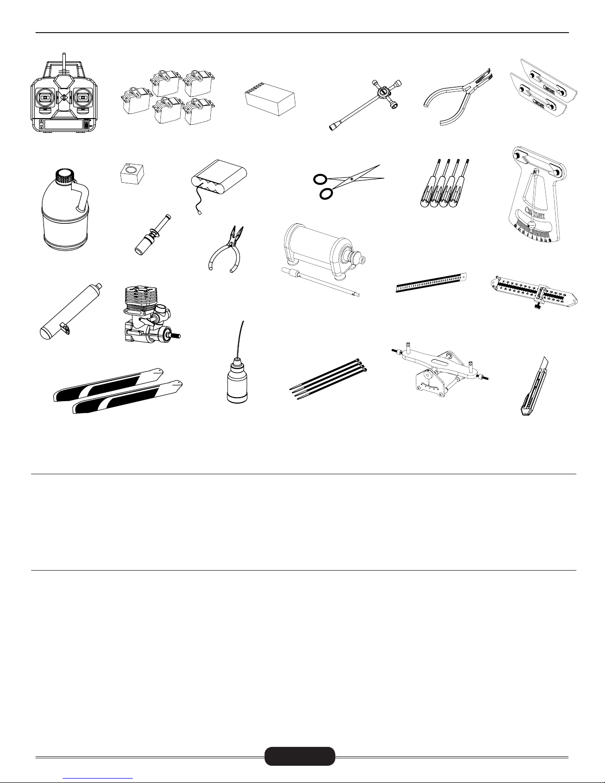
REQUIRED/RECOMMENDED ITEMS
Radikal N640
6 CHANNEL
CCPM TRANSMITTER
(MINIMUM)
1.000
NITRO HELICOPTER
FUEL
CN3038A
SILENT POWER
50 MUFFLER
600-640MM ROTOR BLADES
SERVOS X 5
GYRO
GLOW PLUG
IGNITOR
50-56 SIZE NITRO
ENGINE
6 CHANNEL RECEIVER
(MINIMUM)
RECEIVER BATTERY
NEEDLE NOSE
PLIERS
SYNTHETIC
OIL/GREASE
4-WAY WRENCH
HOBBY SCISSORS
CN2057 & CN0426
STARTER
AND STARTER SHAFT
ZIP TIES
CN2034A
BALL LINK PLIERS
CN2017
HEX DRIVERS
1.5, 2.0, 2.5, 3.0 & 4.0
METRIC RULER OR
SIMILAR MEASURING
DEVICE
CN2051
ACCURATECH BLADE BAL-
ANCER V.2
CN2050
PADDLE GAUGE
CN2027
G-FORCE PITCH GAUGE
CN2255
CONTROL ROD
SETUP GAUGE
HOBBY KNIFE
Warranty
Century Helicopter Products assures the purchaser that should a defect in materials or workmanship occur within 30 days from the
date of purchase affecting the original customer (“Purchaser”) under normal use, Century Helicopter Products will assume warranty
replacement or repair as seen fit. In the event the helicopter is assembled by the Purchaser and damage occurs by the Purchaser of the
final product, Century Helicopter Products shall not be liable. The assembled product by the Purchaser shall accept full responsibility and
liability. If the Purchaser is not prepared to accept such liability associated with the assembly or operation of the model, the kit must be
immediately returned in new and unused condition to the original place of purchase.
Warranty Period
This warranty is limited to the original customer (“Purchaser”) and is non-transferable. THE PURCHASER IS RESPONSIBLE FOR TRANSPORTATION CHARGES OF ANY AND ALL REPAIRS OR REPLACEMENTS PROVIDED UNDER THIS WARRANTY. The warranty coverage
will only apply to those products purchased from an authorized Century Helicopter Products dealer or distributor. This warranty can
change or be modified without any prior notice and shall supersede all other warranties expressed or implied. To initiate a warranty claim,
please be sure you have proof of purchase of the product. Century Helicopter Products reserves the right to inspect any and all items
involved in a warranty claim. Century Helicopter Products does not warrant that the operation of the product will be uninterrupted or
error-free. Century Helicopter Products will not be responsible for damage coming from failure to follow instructions relative to the products assembly and usage. This warranty does not apply to damage caused by products other than Century Helicopter Products’, damage caused by accident, abuse, cosmetic damage, negligence, misuse, flood, fire, earthquake other external causes, commercial use, or
modification of or to any part of the Product. This warranty does not cover damage due to improper installation, operation, maintenance,
or attempted repair by anyone other than Century Helicopter Products.
Page 3

AMA RULES & REGULATIONS
Radikal N640
General
1. Model aircraft will not be flown:
(a) In a careless or reckless manner.
(b) At a location where model aircraft activities are prohibited.
2. Model aircraft pilots will:
(a) Yield the right of way to all man carrying aircraft.
(b) See and avoid all aircraft and a spotter must be used when appropriate. (AMA Document #540-D-See and Avoid Guidance.)
(c) Not fly higher than approximately 400 feet above ground level within three (3) miles of an airport, without notifying the airport
operator.
(d) Not interfere with operations and traffic patterns at any airport, heliport or seaplane base except where there is a mixed use
agreement.
(e) Not exceed a takeoff weight, including fuel, of 55 pounds unless in compliance with the AMA Large Model Aircraft program. (AMA
Document 520-A)
(f) Ensure the aircraft is identified with the name and address or AMA number of the owner on the inside or affixed to the outside of
the model aircraft. (This does not apply to model aircraft flown indoors).
(g) Not operate aircraft with metal-blade propellers or with gaseous boosts except for helicopters operated under the provisions of
AMA Document #555.
(h) Not operate model aircraft while under the influence of alcohol or while using any drug which could adversely affect the pilot’s ability
to safely control the model.
(i) Not operate model aircraft carrying pyrotechnic devices which explode or burn, or any device which propels a projectile or drops
any object that creates a hazard to persons or property.
3. Model aircraft will not be flown in AMA sanctioned events, air shows or model demonstrations unless:
(a) The aircraft, control system and pilot skills have successfully demonstrated all maneuvers intended or anticipated prior to the
specific event.
(b) An inexperienced pilot is assisted by an experienced pilot.
4. When and where required by rule, helmets must be properly worn and fastened. They must be OSHA, DOT, ANSI, SNELL or NOCSAE
approved or comply with comparable standards.
Radio Control (RC)
1. All pilots shall avoid flying directly over unprotected people, vessels, vehicles or structures and shall avoid endangerment of life and
property of others.
2. A successful radio equipment ground-range check in accordance with manufacturer’s recommendations will be completed before
the first flight of a new or repaired model aircraft.
3. At all flying sites a safety line(s) must be established in front of which all flying takes place (AMA Document #706-Recommended
Field Layout):
(a) Only personnel associated with flying the model aircraft are allowed at or in front of the safety line.
(b) At air shows or demonstrations, a straight safety line must be established.
(c) An area away from the safety line must be maintained for spectators.
(d) Intentional flying behind the safety line is prohibited.
4. RC model aircraft must use the radio-control frequencies currently allowed by the Federal Communications Commission (FCC). Only
individuals properly licensed by the FCC are authorized to operate equipment on Amateur Band frequencies.
5. RC model aircraft will not operate within three (3) miles of any pre-existing flying site without a frequency-management agreement
(AMA Documents #922- Testing for RF Interference; #923- Frequency Management Agreement)
6. With the exception of events flown under official AMA Competition Regulations, excluding takeoff and landing, no powered model
may be flown outdoors closer than 25 feet to any individual, except for the pilot and the pilot’s helper(s) located at the flight line.
7. Under no circumstances may a pilot or other person touch a model aircraft in flight while it is still under power, except to divert it
from striking an individual. This does not apply to model aircraft flown indoors.
8. RC night flying requires a lighting system providing the pilot with a clear view of the model’s attitude and orientation at all times.
9. The pilot of a RC model aircraft shall:
(a) Maintain control during the entire flight, maintaining visual contact without enhancement other than by corrective lenses prescribed for the pilot.
(b) Fly using the assistance of a camera or First-Person View (FPV) only in accordance with the procedures outlined in AMA Document
#550.
Free Flight
1. Must be at least 100 feet downwind of spectators and automobile parking when the model aircraft is launched.
2. Launch area must be clear of all individuals except mechanics, officials, and other fliers.
3. An effective device will be used to extinguish any fuse on the model aircraft after the fuse has completed its function.
Page 4
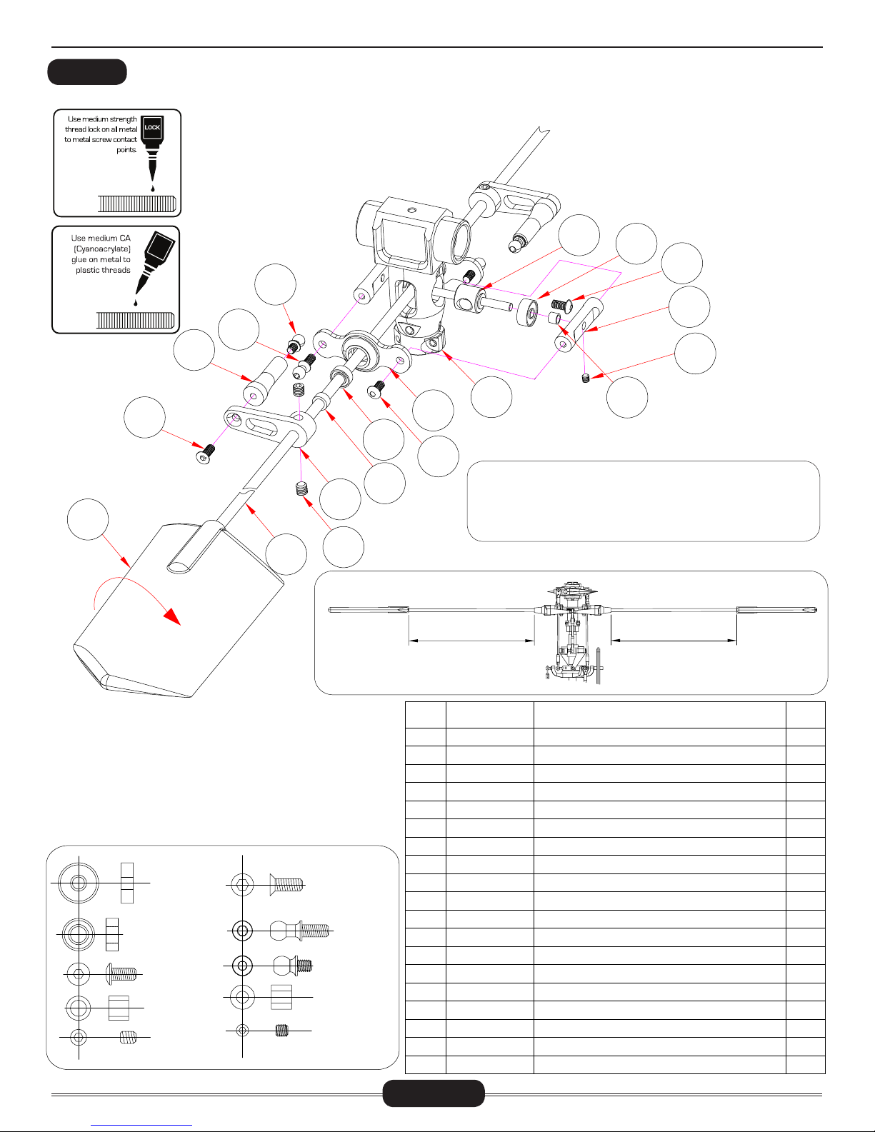
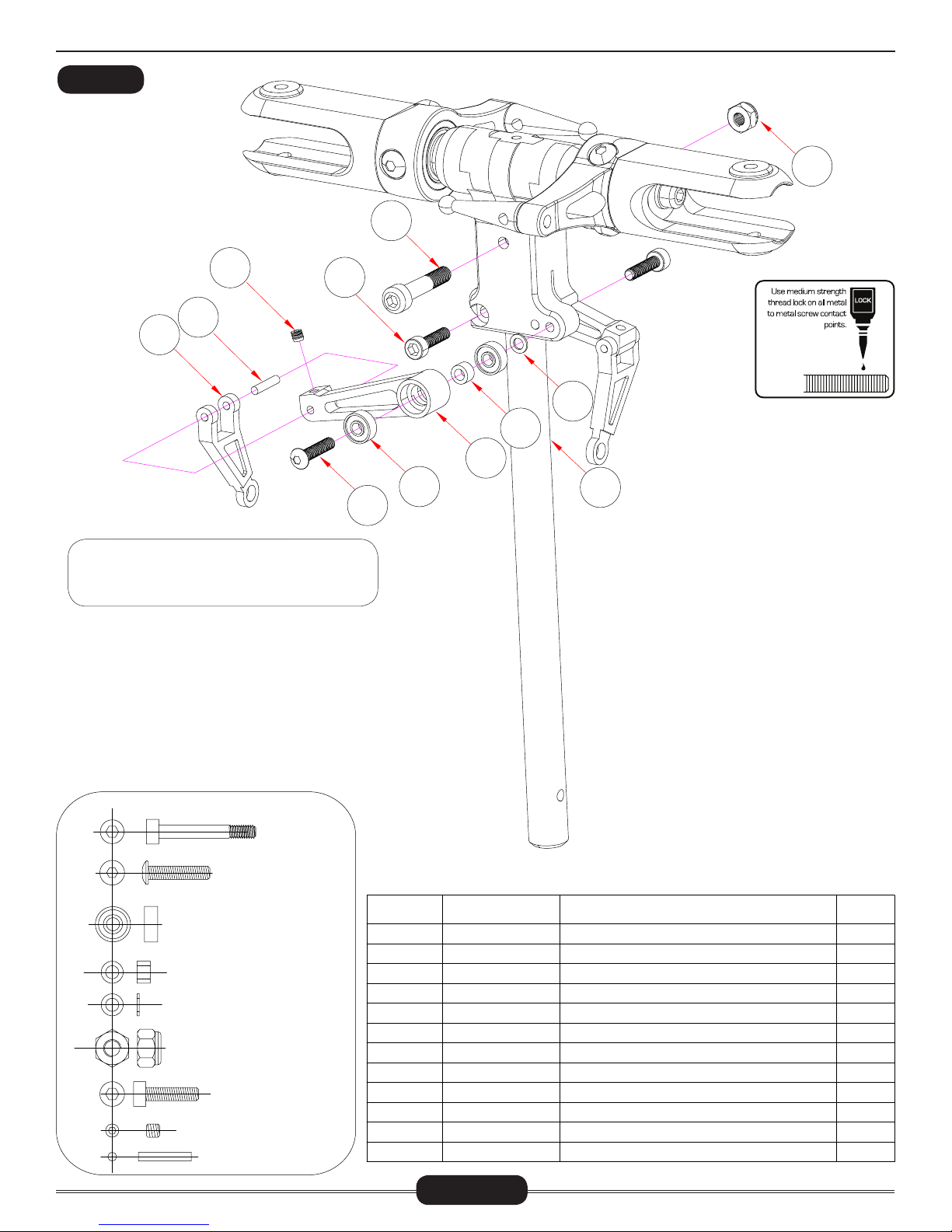
HEAD ASSEMBLY (FLYBAR VERSION)
BAG 1
Do not open all the bags prior to starting assembly. Open the bags step by step as you go through this
instruction manual. The components are bagged to make assembly easier. The next few pages will pertain to the assembly of the head. Please follow the instructions based on the head type you own. Make
sure to apply threadlock to any screws going into metal.
Radikal N640
15
16
C
A
1
2
3
19
4
18
17
7
6
5
8
10
9
The flybar head comes pre-assembled however, it is only assembled as an example of how it should be assembled. The entire
head will need to be taken apart and medium thread lock is
required on all metal to metal parts.
Make sure the distance on
both sides are equal
14
12
13
11
Make sure the distance on
both sides are equal
CNBB1030
CNBB0840
CNM3x6BHCS
4X6X5
CNM4X4SS
CNM3x8FHCS
CNLR1017
CNLR1014
3X6X5
CNM3x3SS
No.
1
2
3
4
5
6
7
8
9
10
11
12
13
14
15
16
17
18
19
Page 5
Part #
CNE518
CNBB1030
CNM3x6BHCS
CNE564S
CNE564S
CNE564S
CNE556-1
HI3167H3
CNM3x6BHCS
CNBB0840
CNE559AS
CNE559AS
CNM4x4SS
HI6179B1
HI3179A
CNM3x8FHCS
CNE559AS
CNLR1017
CNLR1014
Description
Seesaw Shaft( 旋转轴)
3X10X4 Bearing(轴承)
Button Head Cap Screw( 圆头内六角螺丝)
Seesaw Tie Bar Set(平衡杆控制臂)
M3x3 Socket Head Set Screw(无头内六角螺丝)
3x6x5 Spacer( 3x6x5铝套 )
Rotor Head Yoke(主旋翼中心座)
Seesaw Offset Plates(平衡杆固定片)
Button Head Cap Screw(圆头内六角螺丝)
4X8X3 Bearing(轴承)
4X6X5 Spacer(套子)
Flybar Control Arm(平衡翼控制臂)
M4x4 Socket Head Set Screw( 无头内六角螺丝)
4mm Flybar(平衡杆)
Flybar Paddles(平衡翼)
Flush Head Cap Screws(斜头内六角螺丝)M3x8
Flybar Control Arm(平衡翼控制臂)
M3 Ball Link Long(M3球头螺丝)
M3 Ball Link Short(M3 球头螺丝)
Qty
1
2
2
2
2
2
1
2
2
2
2
2
4
1
2
2
2
2
2
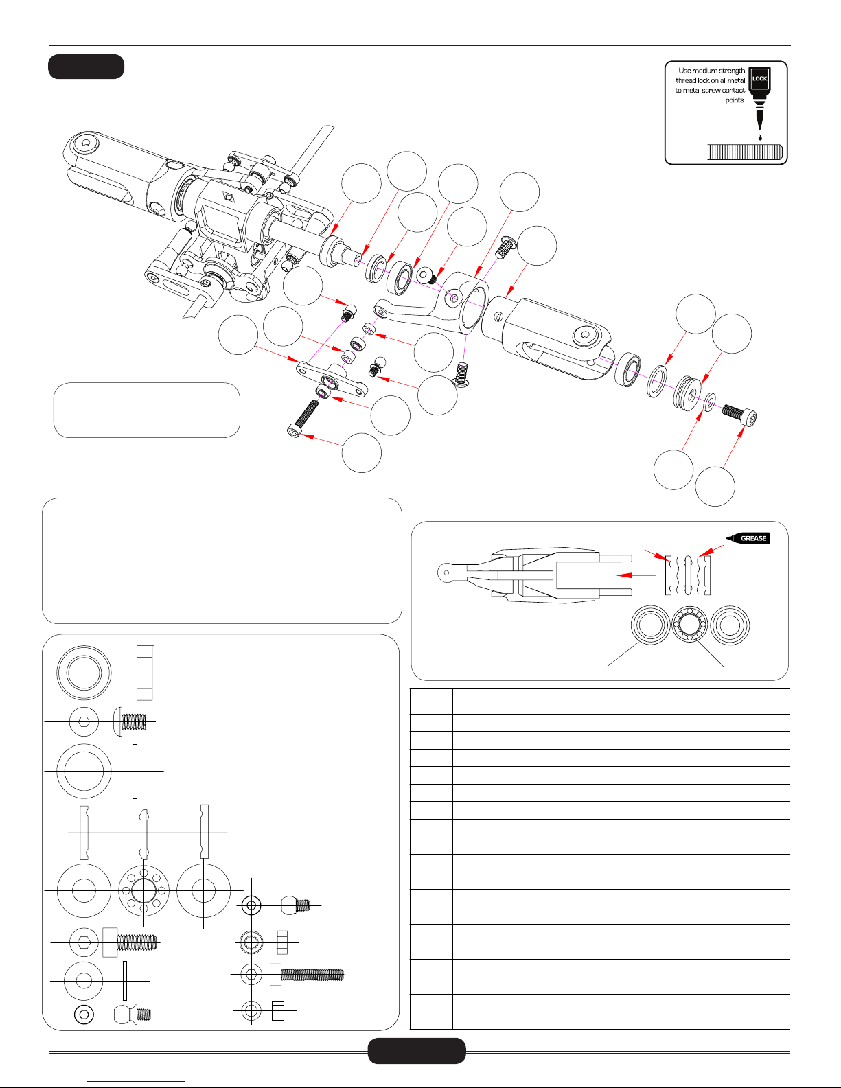
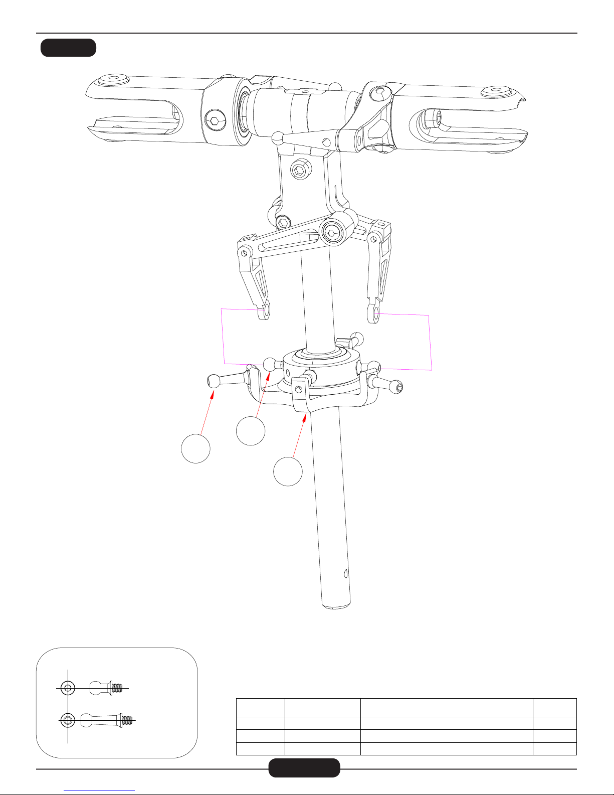
HEAD ASSEMBLY (FLYBAR VERSION)
BAG 1
Radikal N640
1
18
16
Notice the direction of the blade
grips as well as the direction of
the flybar control arm.
Ensure lubricant is applied to the thrust bearings. Be careful when
taking the thrust bearings out of the blade grips. The radial bearings (part #4) should stay within the grips. DO NOT try to remove
these as they have been factory installed. It is best to remove the
grips one side at a time. Before assembly, notice the direction of the
control arm on the grip. It should be assembled as indicated within
this diagram.
17
14
15
2
4
3
5
12
13
THRUST BEARING INSTALLATION GUIDE
SIDE PROFILE - BLADE GRIP
6
7
GROOVES INSIDE
LARGER ID
8
9
11
10
SMALLER ID
CNBB814
CNM4X6BHCS
CNM10X14FW
CNM4x10CS
CNM4X10FW
CNLR1014
CNBB614T
CNLR1023
CNBB364
CNM3X5X3
M3X16CS
No.
1
2
3
4
5
6
7
8
9
10
11
12
13
14
15
16
17
18
Page 6
LARGER INNER DIAMETER TOWARDS HEAD BLOCK
Part #
HI6181D
CNE521A
CNE522-28
CNBB814
CNM4x6BHCS
CNE557-2
CNE557A-1
CNM10X14FW
CNBB614T
CNM4X10CS
CNM4X10FW
HW6206
CNLR1014
CNBB364
CNM3X16CS
CNE558S
HW6205
CNLR1023
RECESSED CREVICE FACES MAIN SHAFT
Description
Rubber Dampener( 橡皮环)
Feathering Shaft( 横轴)
T=2.8mm, Blade Grip Spacer
8X14X4Bearing( 轴承)
Button Head Cap Screw(圆头内六角螺丝)
Main Rotor Blade Grip Arms(主旋翼夹片臂)
Main Rotor Blade Grips(主旋翼夹片座)
M10x14x1Flat Washer(平面垫片)
6x14x5 Thrust Bearing(止推轴承)
M4x10 Cap Screws( 杯头螺丝)
M4x10x1Flat Washer(平面垫片)
3X5X2 Spacer(固定套)
M3 Ball Link(M3 球头螺丝)
3X6X2.5Bearing( 轴承)
M3x16 Cap Screws(杯头螺丝)
Bell Mixer Arm(混控臂)
3X5X3 Brass Spacer(固定套)
M3 Ball Link(M3 球头螺丝)
( 间隔套)
Qty
2
1
2
4
6
2
2
2
2
2
2
2
2
4
2
2
2
2
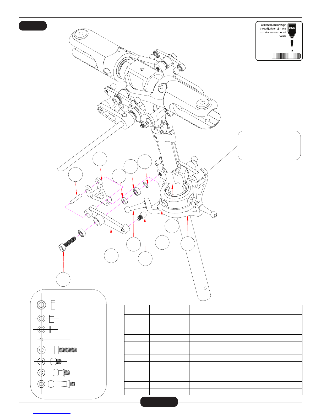
HEAD ASSEMBLY (FLYBAR VERSION)
BAG 1
1
6
Radikal N640
C
A
2
4
Do not over-tighten!
3
5
M3X8CS
CNM3X22SCS
M3 CNM3LOCK
CNM3x3S S
No.
1
2
3
4
5
6
Part #
CNM3LOCK
CNM3X8CS
HW5053
CNM3x3SS
CNE556-2
CNM3X22SCS
Page 7
Description
M3 Locknut(M3螺母)
M3x8 Cap Screws(杯头螺丝)
10mm Main Shaft(主轴)
M3x3 Socket Head Set Screw(无头内六角螺丝)
Aluminum Washout Guide(剪型臂导柱
M3x22 Cap Screws(杯头螺丝)
)
Qty
1
2
1
2
1
1
HEAD ASSEMBLY (FLYBAR VERSION)
BAG 1
4
1
2
5
3
Radikal N640
Hint: To ensure this pin does
not pop out, periodically
check it between flights. You
also can apply a tiny drop of
CA to either side of the pin.
6
CNBB36
CNM3X5X3
M3x5x0.5 CNLR1003
Ø2x12
M3X12CS
CNLR1023
CNLR1020
M3 L=18MM
7
8
No.
1
2
3
4
5
6
7
8
9
10
11
12
9
CNLR1003
CNBB36
HW6205
CNE516B
CNE516B
CNM3X12CS
CNE560S
CNLR1021
CNLR1023
CNLR1011
CNE594
HW5146N
10
Part #
11
12
Description
3X5X0.5 Flat Washer(平面垫片)
3X6X2.5 Bearing(轴承)
3X5X3 Brass Spacer(固定套)
Radius Link w/ Pin( 三角控制臂)
Radius Link w/ Pin( 插销)
M3x12 Cap Screws( 杯头螺丝)
Washout Arm(摆臂)
M3 Ball Link L=18MM(M3 球头螺丝)
M3 Ball Link(M3 球头螺丝)
M3 Ball Link(M3 球头螺丝)
Washout Hub (控制臂固定座)
NX Dual Ball Bearing Swashplate(
十字盘)
Qty
2
4
2
2
2
2
2
2
2
4
1
1
Page 8

LINKAGE RODS (FLYBAR VERSION)
BAG 1
1
A
2
Radikal N640
NOTICE SIZE OF HOLES ON BALL LINKS
THE SIDE WITH THE SMALLER HOLE
SHOULD FACE OUTWARDS
D
9
8
7
3
B
4
5
C
6
A
B
C
D
25
14
51,5
30
54,5
35
97
80
The linkage rods come pre-built. Even
though they are pre-built, you will need
to verify their lengths. The diagram
with lengths are drawn at a true to
life scale, therefore you can lay your
linkages on the diagram to find the
correct measurements.
No.
Part #
1
HI6145
2
HW5192
3
HI6145
4
HW5192
5
HI6145
6
HW5192
7
HI6145
8
HW5192
9
CNLR1022SP
Page 9
HEL PFUL TOOL
PART# CN2255: CONTROL ROD SETUP GAUGE
Description
Ball Link Set (26 Long, 4 Short)(球头连接杆)
Pushrod Set( 连杆)
Ball Link Set (26 Long, 4 Short)(球头连接杆)
Pushrod Set( 连杆)
Ball Link Set (26 Long, 4 Short)(球头连接杆)
Pushrod Set( 连杆)
Ball Link Set (26 Long, 4 Short)(球头连接杆)
Pushrod Set( 连杆)
Special Ball Link (M3 十字盘特殊球头螺丝)
Qty
4
2
4
2
4
2
4
2
1
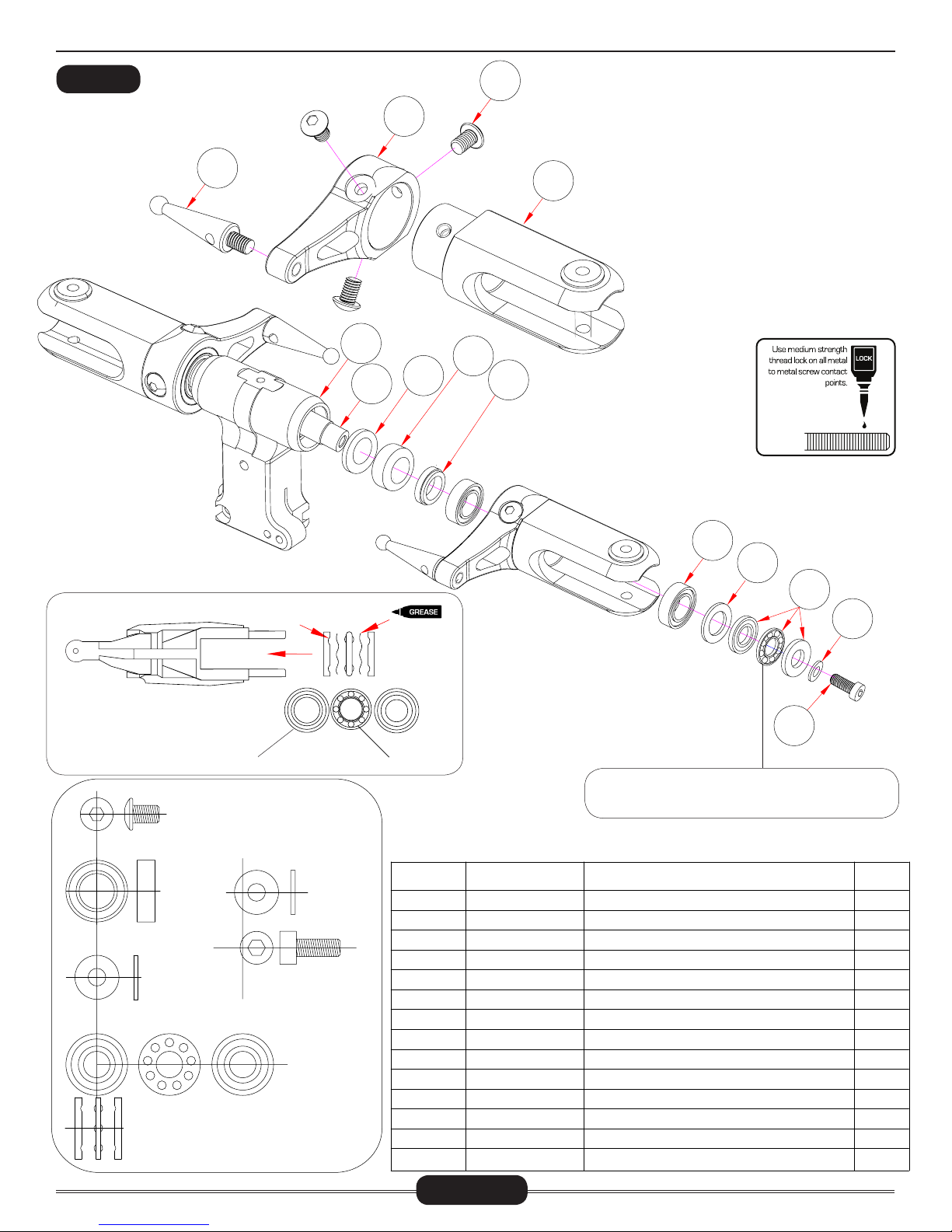
HEAD ASSEMBLY (FLYBARLESS)
Radikal N640
BAG 1
1
5
6
2
7
8
3
9
4
The flybarless head comes pre-assembled
however, it is only assembled as an example of how it should be assembled. The
entire head will need to be taken apart and
medium thread lock is required on all metal
to metal parts. Ensure lubricant is applied
to the thrust bearings. Be careful when
taking the thrust bearings out of the blade
grips. The radial bearings (part #9) should
stay within the grips. DO NOT try to remove
these as they have been factory installed.
It is best to remove the grips one side at a
time. Before assembly, notice the direction
of the control arm on the grip. It should be
assembled as indicated within this diagram.
THRUST BEARING INSTALLATION GUIDE
SIDE PROFILE - BLADE GRIP
LARGER INNER DIAMETER TOWARDS HEAD BLOCK
CNM4x6BHCS
CNBB814
4x10x1
CNBB614T
Parts diagrams are drawn on a 1-to-1 scale.
GROOVES INSIDE
LARGER ID
M4X10X1
CNM4X10CS
SMALLER ID
RECESSED CREVICE FACES MAIN SHAFT
No.
1
2
3
4
5
6
7
8
9
10
11
12
13
14
Page 10
Part #
CN2517A-1
CN2517A-1
CNM4x6BHCS
CN2517A-1
CN2517A-2
CNE521A
CN2517A-6
HI6181D
CN2517A-25
CNBB814
CNM10X14FW
CNBB614T
CNM4X10FW
CNM4X10CS
10
11
12
13
14
Make sure the open ball side of the thrust bearing
is facing towards the rotor head.
Description
Flybarless Arm Ball(摆臂)
Flybarless Arm(摆臂座)
Button Head Screw( 圆头螺丝)M4x6
Main Rotor Blade Grip(主桨夹片)
Head Block(主旋翼中心座)
Feathering Shaft( 横轴)
Head Damper Spacers(塑料圈)
Rubber Dampener( 橡皮环)
T=2.50mm Spacer
8x14x4 Bearing( 轴承)
Flat Washer(垫片)10x14x1
Thrust Ball Bearing( 止推轴承)6x14x5
M4x10x1 Spacer( 垫圈)
M4x10 Cap Screws(杯头螺丝)
( 铝套)
Qty
2
2
6
2
1
1
2
2
2
4
2
2
2
2
HEAD ASSEMBLY (FLYBARLESS)
BAG 1
1
Radikal N640
12
3
2
4
5
6
The follower arms already come pre-assembled.
DO NOT try to remove the bearings as they are
factory installed.
7
11
9
8
10
CNM3X22SCS
CNM3x16BHCS
CNBB0830
M3x5x3 HW6205
M3x5x0.5 CNLR1003
CNM3LOCK
CNM3x12CS
CNM3X3SS
Ø2x12
No.
1
2
3
4
5
6
7
8
9
10
11
12
Part #
CNM3X22SCS
CNM3X12CS
CNM3X3SS
CN2517A-5
CN2517A-5
CNM3x16BHCS
CNBB0384
CN2517A-5
HW6205
HW5053A
CNLR1003
CNM3LOCK
Page 11
Description
M3x22 Cap Screws(杯头螺丝)
M3x12 Cap Screws(杯头螺丝)
M3x3 Socket Head Set Screw
Radius Link w/ Pin(插销)
Radius Link w/ Pin( 三角控制臂)
Button Head Cap Screw( 圆头内六角螺丝)M3x16
Bearing(滚珠轴承)3x8x3
Washout Control Arm( 剪型臂)
Spacer(铁套)3x5x3
10mm Main Shaft(主轴)
3x5x0.5 Micro Washer( 垫圈)
M3 Locknut (M3
防松螺母)
(无头内六角螺丝)
Qty
1
2
2
2
2
2
4
2
2
1
2
1
HEAD ASSEMBLY (FLYBARLESS)
BAG 1
Radikal N640
CNLR1020
M3 L=18MM
1
2
No.
1
2
3
3
Part #
CNLR1021
CNLR1020
HW5146N
Description
M3 Ball Link L=18MM(M3 球头螺丝)
M3 Ball Link(M3 球头螺丝)
NX Dual Ball Bearing Swashplate(十字盘)
Qty
3
4
1
Page 12
 Loading...