

Page 1

Kit Features:
Specifications:
Lightweight yet extremely strong G10 or carbon fiber frames.
High gloss large diameter 25mm tail boom with belt drive system.
Blade grips accommodate blades 12mm (LT) to 18mm (HD) blade roots.
300 mL fuel tank for long engine run time.
Convenient and easy access to spark plug.
Triple bearing supported blade grips and tail blade grips.
Machined center dual ball bearing swashplate for 120 degree CCPM.
Adjustable bell-hiller ratio allows tuning for preferred cyclic response (HD)
Tunable flight characteristics for stability or speed.
© 2010 Century Helicopter Products - All rights reserved.
Length: 1366mm
Height: 381mm
Width: 260mm
Main rotor diameter: 1435mm
Tail rotor diameter: 262mm
Main rotor blades: 600mm-640mm
Tail rotor blades: 95mm
Version 1.10
Page 2

INTRODUCTION
Radikal Gasser
Thank You
Congratulations on the purchase of the latest Century Gasser series, the Radikal G20. You’re about to build one of the world’s first fully
functional 3D aerobatic helicopters powered by the Zenoah 20cc gasoline engine. Be sure to read through and follow the instructions
during the build.
Warning
This radio controlled model is not a toy! It is a precision machine requiring proper assembly and setup to avoid accidents. It is the
responsibility of the owner to operate this product in a safe manner as it can inflict serious injury otherwise. It is recommended that if
you are in doubt of your abilities, seek assistance from experienced radio control modelers and associations. Keep loose items that can
get entangled in the rotor blades away for the main and tail blades, including loose clothing, hair, or other objects such as pencils and
screwdrivers. Especially keep your hands away from the rotor blades. As manufacturer, we assume no liability for the use of this product.
Flight Guidelines
Please note this checklist is not intended to be a replacement for the content included in this instruction manual. Although it can
be used as a quick start guide, we strongly suggest reading through this manual completely before proceeding.
Always turn the transmitter on first
Allow the gyro, and receiver to arm and initialize properly
Do a pre-flight check making sure all electronics are working and look for any mechanical issues
Fly the model
Land the model
Turn off the engine
Always turn the transmitter off last
General Guidelines
Apply thread lock to all metal to metal thread contact points. Do not apply CA (cyanoacrylate) glue or thread lock to ny-lock nuts (metal nuts
with plastic inserts). Diagrams indicated by bounding boxes for screws, bearings, etc. are illustrated at a 1-to-1 ratio. All other illustrations
are not drawn to scale. Throughout this manual, you will find building tips. Please follow the tips and use common sense when building.
Pre-assembly Information
Various assemblies have been pre-assembled however, only as a reference assembly. Final assembly is up to the user. Installation onto
the particular parts, screws and nuts required for each step are packaged in the same bag as the parts. Be careful when opening each
bag as not to lose any hardware. Care has been taken in filling and packing of each bag however mistakes do happen. If there is a parts
shortage or missing hardware please contact us at:
.launam eht fo snoitces eht ot dnopserroc hcihw ylbmessa fo esae rof deggab era strap tnenopmoc rojam eht lla ,tik eht gninepo nopU
Century Helicopter Products
1740-C Junction Ave.
San Jose, CA. 95112
www.centuryheli.com
Page 2
Page 3
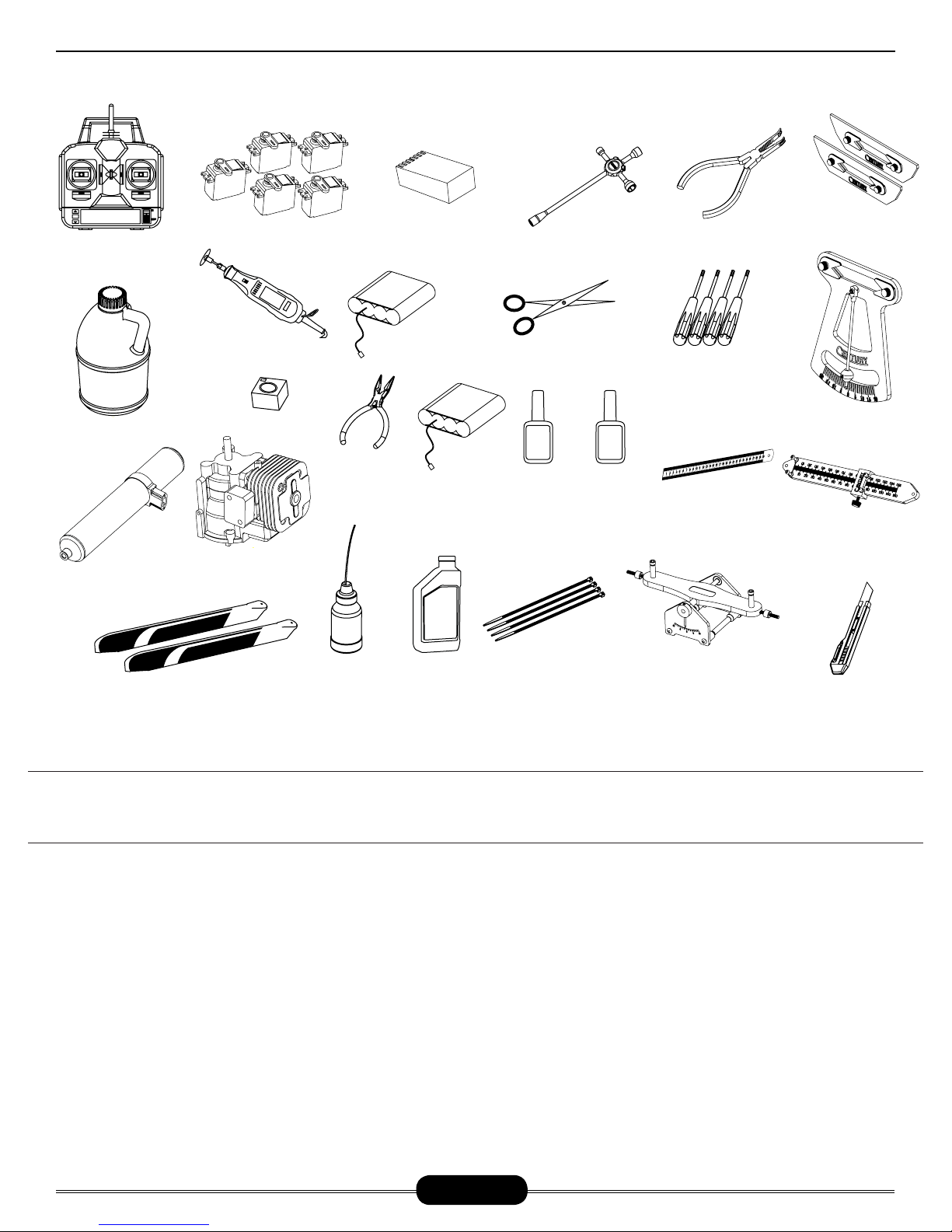
REQUIRED ITEMS
Radikal Gasser
6 CHANNEL
CCPM TRANSMITTER
(MINIMUM)
1.000
87 TO 92 OCTANE
GASOLINE
CN3070
20cc TORPEDO
GASSER TUNED
MUFFLER
600MM TO 660MM
MAIN ROTOR BLADES
DREMEL TOOL
OR SIMILAR
GYRO
1.000
20CC ZENOAH
GASOLINE ENGINE
SERVOS X 5
OIL/GREASE
NEEDLE NOSE
PLIERS
SYNTHETIC
6 CHANNEL RECEIVER
(MINIMUM)
RECEIVER BATTERY
ELECTRONIC
I G N I T I O N
BATTERY
2-STROKE
MOTOR OIL
CN2031
4-WAY WRENCH
HOBBY SCISSORS
SLOW &
Medium CA
GLUE
ZIP TIES
HEX DRIVERS
1.5, 2.0, 2.5, 3.0, 4.0, 5.0
Medium
(Medium)
THREAD-
LOCK
METRIC RULER OR
SIMILAR MEASURING
ACCURATECH BLADE BAL-
ANCER V.2
CN2034A
BALL LINK PLIERS
CN2017
DEVICE
CN2051
CN2050
PADDLE GAUGE
CN2027
G-FORCE PITCH GAUGE
CN2255
CONTROL ROD
SETUP GAUGE
HOBBY KNIFE
Warranty Period
Century Helicopter Products warranties that the Products purchased (the “Product”) will be free from defects in materials and workmanship 30 days from the date of purchase by the Purchaser.
Limited Warranty
(a) This warranty is limited to the original customer (“Purchaser”) and is not transferable. REPAIR OR REPLACEMENT AS PROVIDED
UNDER THIS W ARRANTY I S THE EXCLUSIVE R EMEDY OF T HE PURCHASER. This warranty covers only those P roducts purchased
from an authorized Century Helicopter Products dealer. Third party transactions are not covered by this warranty. Proof of purchase is
required for warranty claims. Further, Century Helicopter Products reserves the right to change or modify this warranty without notice
and disclaims all other warranties, express or implied.
(b) Limitations- CENTURY HELICOPTER PRODUCT MAKES NO WARRANTY OR REPRESENTATION, EXPRESS OR IMPLIED, ABOUT NONINFRINGEMENT, MERCHANTABILITY OR FITNESS FOR A PARTICULAR PURPOSE OF THE PRODUCT. THE PURCHASER ACKNOWLEDGES THAT THEY ALONE HAVE DETERMINED THAT THE PRODUCT WILL SUITABLY MEET THE REQUIREMENTS OF THE PURCHASER’S
INTENDED USE.
(c) Purchaser Remedy- Century Helicopter Products’s sole obligation hereunder shall be t hat Century Helicopter Products will, at its
option, (i) repair or (ii) replace, any Product determined by Century Helicopter Products to be defective. In the event of a defect, these
are the Purchaser’s e xclusive remedies. Century Helicopter Products reserves the right to inspect any and a ll equipment involved in
a warranty claim. Repair or replacement decisions are at the sole discretion of Century Helicopter Products. This warranty does not
cover cosmetic damage or damage due to acts of God, accident, misuse, abuse, negligence, commercial use, or modification of or to any
part of the Product. This warranty does not cover damage due to improper installation, operation, maintenance, or attempted repair by
anyone other than Century Helicopter Products. Return of any goods by Purchaser must be approved by Century Helicopter Product s
before shipment.
Page 3
Page 4

AMA RULES & REGULATIONS
Radikal Gasser
General
1) I will not fly my model aircraft in sanctioned events, air shows or model flying demonstrations until it has been proven to be airworthy by having been previously, successfully flight tested.
2) I will not fly my model higher than approximately 400 feet within 3 miles of an airport without notifying the airport operator. I will
give right-of-way and avoid flying in the proximity of full-scale aircraft. Where necessary, an observer shall be utilized to supervise flying
to avoid having models fly in the proximity of full-scale aircraft.
3) Where established, I will abide by the safety rules for the flying site I use, and I will not willfully or deliberately fly my models in a
careless, reckless and/or dangerous manner.
4) The maximum takeoff weight of a model is 55 pounds, except models flown under Experimental Aircraft rules.
5) I will not fly my model unless it is identified with my name and address or AMA number on or in the model. (This does not apply to
models while being flown indoors.)
6) I will not operate models with metal-bladed propellers or with gaseous boosts, in which gases other than air enter their internal
combustion engine(s); nor will I operate models with extremely hazardous fuels such as those containing tetranitromethane or hydrazine.
Radio Control
1) I will have completed a successful radio equipment ground range check before the first flight of a new or repaired model.
2) I will not fly my model aircraft in the presence of spectators until I become a qualified flier, unless assisted by an experienced helper.
3) At all flying sites a straight or curved line(s) must be established in front of which all flying takes place with the other side for
spectators. Only personnel involved with flying the aircraft are allowed at or in front of the flight line. Intentional flying behind the flight
line is prohibited.
4) I will operate my model using only radio control frequencies currently allowed by the Federal Communications Commission. (Only
properly licensed Amateurs are authorized to operate equipment on Amateur Band frequencies.)
5) Flying sites separated by three miles or more are considered safe from site-to site interference, even when both sites use the
same frequencies. Any circumstances under three miles separation require a frequency management arrangement, which may be
either an allocation of specific frequencies for each site or testing to determine that freedom from interference exists. Allocation
plans or interference test reports shall be signed by the parties involved and provided to AMA Headquarters. Documents of agreement and reports may exist between
(1) Two or more AMA Chartered Clubs, (2) AMA clubs and individual AMA members not associated with AMA Clubs, or (3) two or
more individual AMA members.
6) For Combat, distance between combat engagement line and spectator line will be 500 feet per cubic inch of engine displacement.
(Example: .40 engine = 200 feet.); electric motors will be based on equivalent combustion engine size. Additional safety requirements
will be per the RC Combat section of the current Competition Regulations.
7) At air shows or model flying demonstrations, a single straight line must be established, one side of which is for flying, with the
other side for spectators.
8) With the exception of events flown under AMA Competition rules, after launch, except for pilots or helpers being used, no powered
model may be flown closer than 25 feet to any person.
9) Under no circumstances may a pilot or other person touch a powered model in flight.
Page 4
Page 5
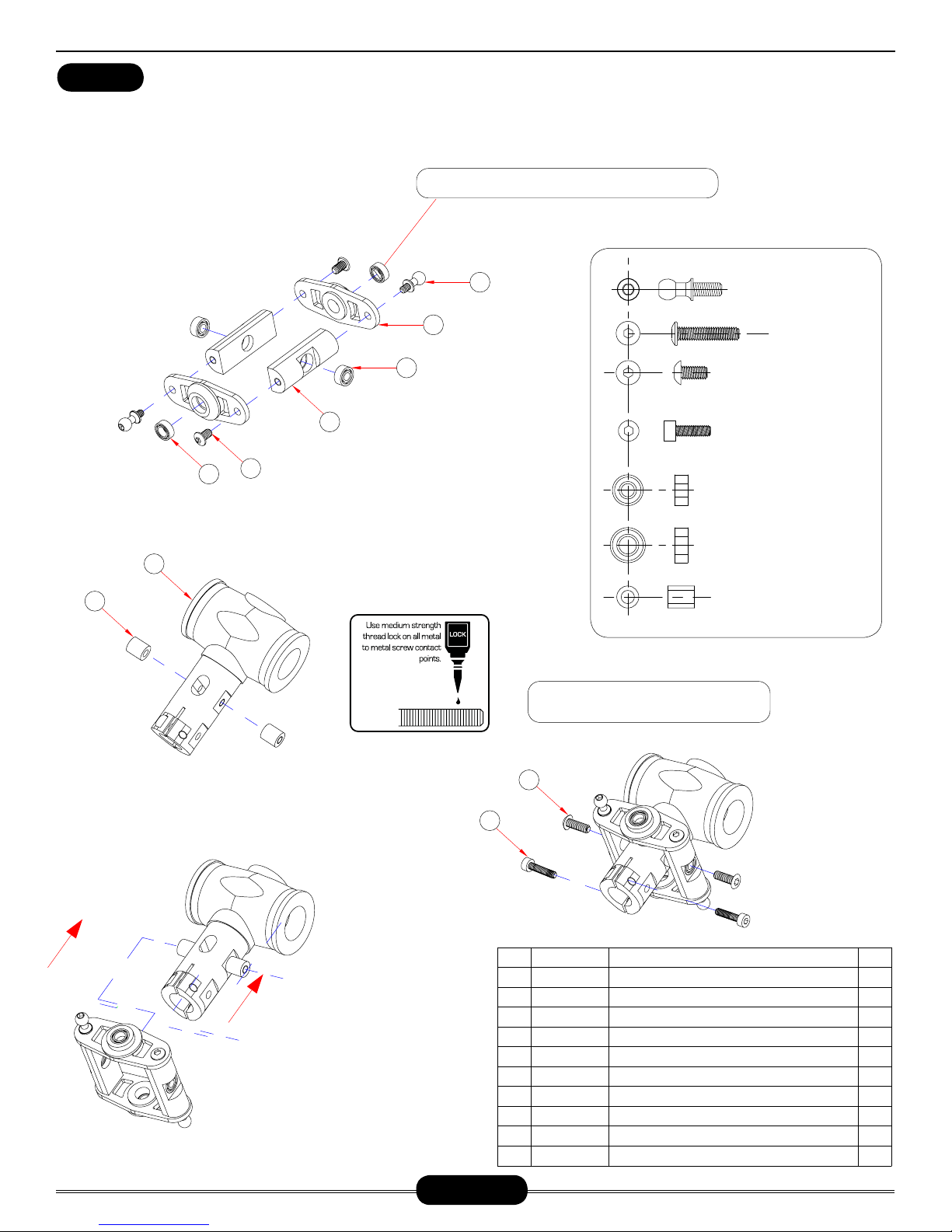
HEAD ASSEMBLY (HD VERSION)
Radikal Gasser
BAG 1
Do not open all the bags prior to starting assembly. Open the bags step by step as you go through the instruction manual. The
components are bagged to make assembly easier. The next few pages will pertain to the assembly of the head. Please follow
the instructions based on the head type you own. Make sure to apply threadlock to any screws going into metal.
Take special care when pressing in these bearings. Do not
Insert one ball bearing into each bearing cup and insert into
the offset plate. Apply one small drop of slow cyanoacrylate
glue (Slow CA) to the joint between the backside of the
bearing cup and the offset plate. Insert one ball
bearing into each tie bar. Using an available
M3 socket cap screw, form threads
into both ends of the tie
bars. Insert one
M3x6 button head
screw through
the right side
hole of the
offset plate
and thread
into one
tie bar.
4
bar bearing, slide one steel spacer
and carefully apply Medium threadlock to
5
6
the exposed threads and insert into the right
side of the head block. Do not overtighten. Repeat
for the second sub-assembly. Once complete apply
a small amount of slow cyanoacrylate glue and insert one
CNLR1020 special long thread ball into each offset plate to com-
plete the assembly.
7
press in on the inner sleeve of the bearing
1
M a k e
t w o
2
i d e n t i c a l
s u b a s s e m -
blies . Note that
3
the bearing cups face
outwards from the head
block. Insert one M3x14 but-
ton head screw through the tie
CNLR1017 L=6.5MM
CNM3X14BHCS
CNM3X6BHCS
CNM2.5X8CS
CNBB0730
CNBB0840
8
Do not secure all the screws until lining up the
components in the following steps.
HI3167G
9
10
No.
1
2
3
4
5
6
7
8
9
10
Part #
CNLR1017
HI3167B
CNBB0730
HI3167G
CNM3X6BHCS
CNBB0840
HI6160A
HI3167G
CNM3X14BHCS
CNM2.5X8CS
Stainless Ball, 3mm Thread, Medium(M3球头螺丝)
Seesaw Offset Plates( 平衡杆固定片)
3x7x3 Ball Bearing( 轴承)
Seesaw Tie Bar Set( 平衡杆控制臂)
M3x6 Button Head Cap Screws( 伞头螺丝)
4x8x3 Ball Bearing( 轴承)
NX Rotor Head Yoke(主旋翼中心座)
3x5x6 Seesaw Tie Bar Set( 铁套)
M3x14 Button Head Cap Screws( 伞头螺丝)
M2.5x8 Cap Screws( 杯头螺丝)
Description
Qty
2
2
2
2
2
2
1
2
2
2
Page 5
Page 6
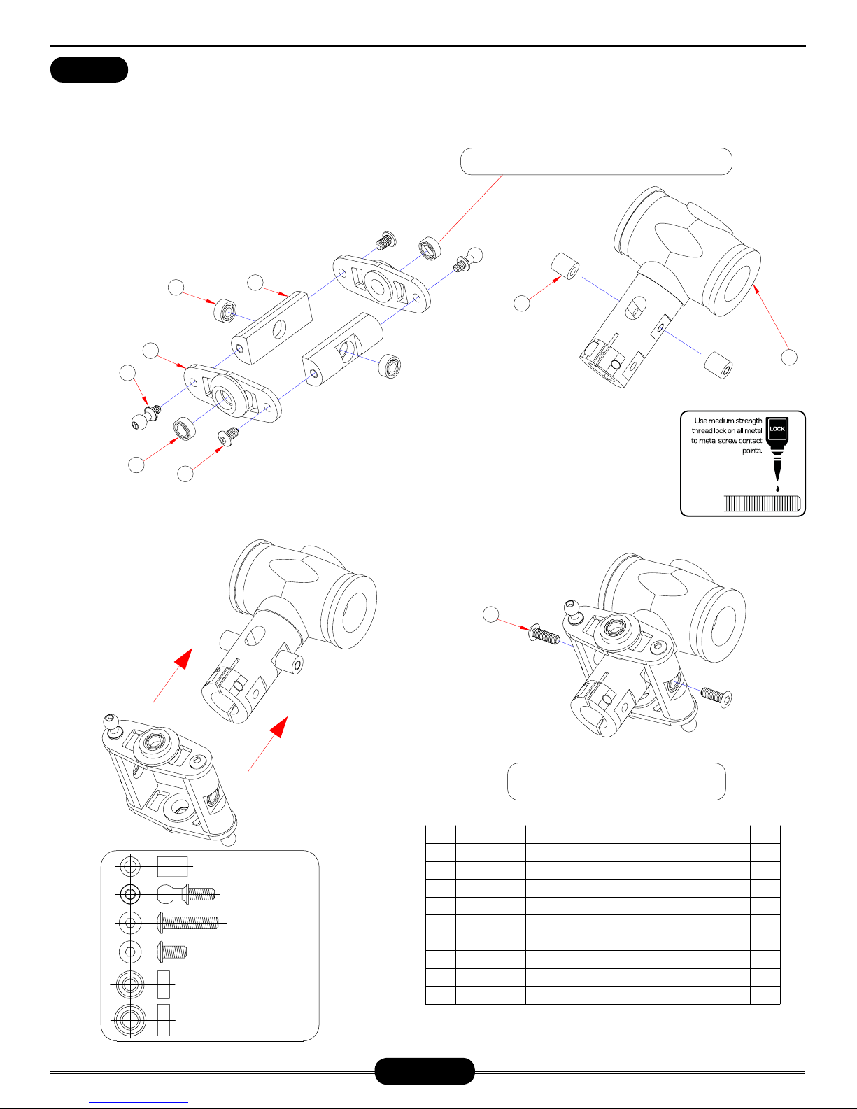
HEAD ASSEMBLY (LT VERSION)
Radikal Gasser
BAG 1
Do not open all the bags prior to starting assembly. Open the bags step by step as you go through the instruction manual. The
components are bagged to make assembly easier. The next few pages will pertain to the assembly of the head. Please follow
the instructions based on the head type you own. Make sure to apply threadlock to any screws going into metal.
Take special care when pressing in these bearings. Do not
Insert one ball bearing into each bearing cup and insert into
the offset plate. Apply one small drop of slow cyanoacrylate
glue (Slow CA) to the joint between the backside of the
bearing cup and the offset plate. Insert one ball
bearing into each tie bar. Using an available
M3 socket cap screw, form threads
into both ends of the tie
bars. Insert one
M3x6 button head
5
6
screw through
the right side
hole of the
offset plate
and thread
into one
4
3
tie bar.
bearing, slide one steel spacer and care-
fully apply Medium threadlock to the exposed
2
1
threads and insert into the right side of the head
block. Do not overtighten. Repeat for the second
sub-assembly. Once complete apply a small amount of
slow cyanoacrylate glue and insert one CNLR1020 special
long thread ball into each offset plate to complete the assembly.
face outwards from the head
block. Insert one M3x14 but-
ton head screw through the tie bar
press in on the inner sleeve of the bearing
7
Make two identical
subassemblies . Note
that the bearing cups
9
3x5x7.5
CNM3x6BHCS
CNBB37
CNBB48
CNLR1017 L=6.5MM
CNM3x14BHCS
No.
CNM3x6BHCS
1
CNBB48
2
CNLR1017
3
HI3167B
4
CNBB0730
5
HI3167G
6
HI3167S
7
CNM3x14BHCS
8
HI6160A
9
Part #
8
Do not secure all the screws until lining up the
components in the following steps.
Description
Button Head Screw( 圆头螺丝)M3x6
Bearing(滚珠轴承)4x8x3
Stainless Ball, 3mm Thread, Medium(M3球头螺丝)
Seesaw Offset Plate(平衡杆控制器)
Bearing(滚珠轴承)3x7x3
Seesaw Offset Plate 2(平衡杆控制器2)
3x5x7.5 Seesaw Tie Bar Set(
Button Head Screw( 圆头内六角螺丝)M3x14
Head Block(主旋翼中心座)
铁套)
Qty
2
2
2
2
2
2
2
2
1
Page 6
Page 7
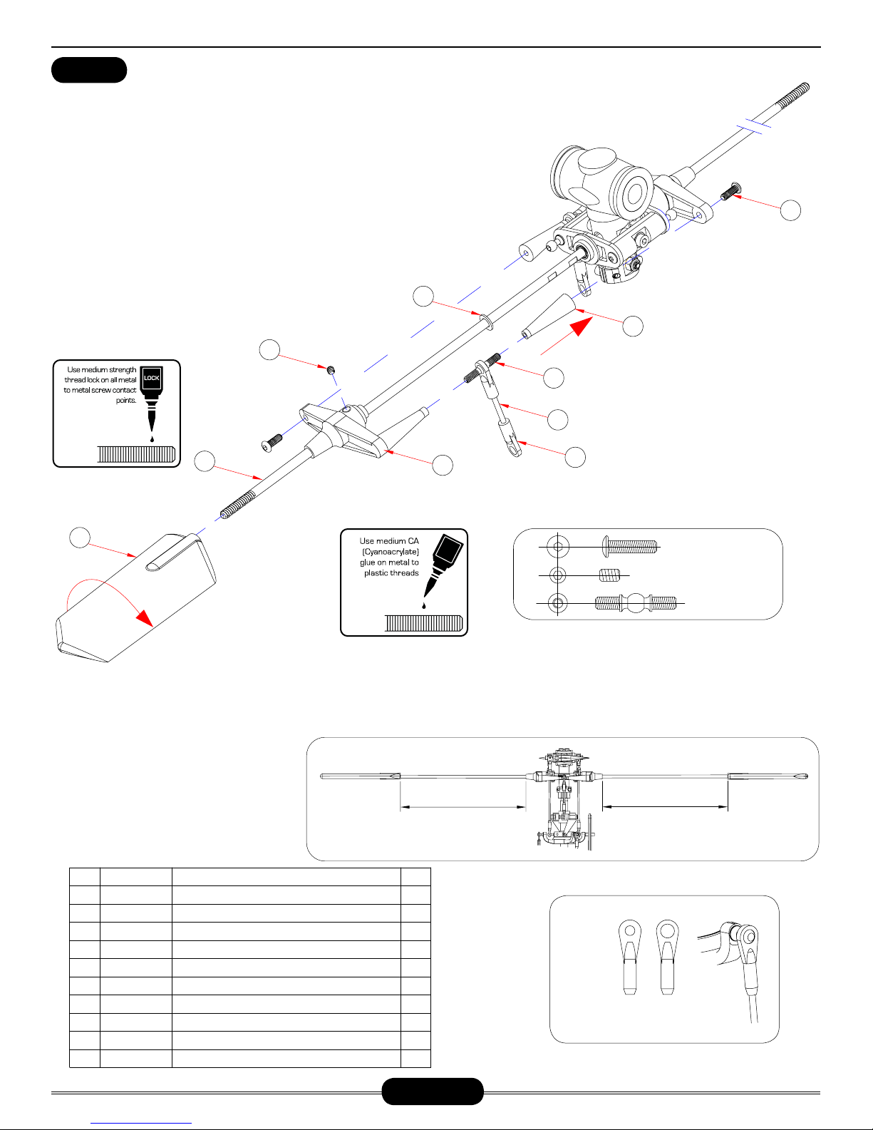
HEAD ASSEMBLY (HD VERSION)
BAG 1
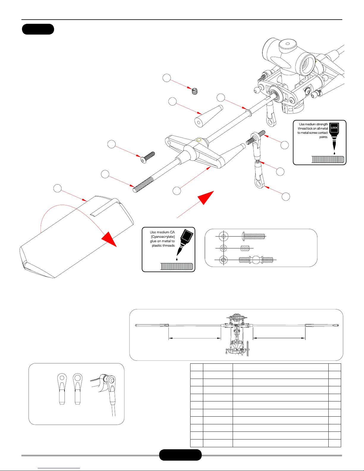
Pushrod assembly (parts 2 through 4) is already assembled but check that the length is
actually 43mm (center to center). As the pushrods are built and installed they should be
checked for tightness. Press one ball link onto each double studded steel ball, making sure
that pressure is applied from the side of the ball link with circle mark. While holding one flybar control arm, apply a small amount of slow cyanoacrylate glue and thread one end of the
double studded steel ball into each standoff. When it becomes difficult to turn with fingers,
apply slow CA to the threads and start screwing in the tapered control arm stand-off on
the other end of the ball. Slide and center the flybar through the head assembly. Carefully look at the flybar control arm assemblies from the previous step and notice
that when installed correctly, the securing set screw is on top. Insert one
M4x6x0.5 micro washer #CNLR1006 against each bearing then slide
the control arm halves onto each side, so that they match together and the set screw remains on top. Insert one M3x12 button head socket screw to secure the opposite standoff.
Hold the tapered standoff using pliers while tightening the screw as the rotor head
rotates clockwise.
9
8
10
1
Radikal Gasser
6
Apply a small amount of cya-
noacrylate glue to the special
5
4
All ball links are molded to be in-
3
stalled in only one direction. Look
carefully at the hole for the ball
as that side is 1mm larger .
2
long thread ball.
7
C
A
CNM3X12BHCS
CNM4X5SS
HW3176C
Loosely tighten the M4x5 set screws into the round aluminum inserts aligned with the flat spots on the flybar. Tighten both set screws, one
at a time using Medium threadlock. Make a pencil mark 5mm past the threads on both ends of the flybar. Thread the flybar paddles onto the
flybar until the mark is reached and align the paddles parallel. Again using the ruler, rotate one paddle or the other to get equal distances while
remembering the leading edge of the paddles turn clockwise.
No.
HI3176C
1
HI6145
2
HW6192
3
4
HI3176C
5
HI3176C
CNM3X12BHCS
6
HI6179B
7
HW3173A
8
CNM4X5SS
9
CNLR1006
10
Part #
Description
Flybar Arms(
Ball Link Set(球头连接头)
Pushrod Set( 拉杆)
Flybar Arms(
Flybar Arms(
M3x12 Button Head Cap Screws( 圆头螺丝)
Flybar Paddles( 平衡翼)
4mm Flybar 500mm(
M4x5 Socket Head Set Screw( 无头内六角螺丝)
M4X6X0.5 Washer( 平面垫片)
平衡翼控制臂)
球头双牙螺丝)
平衡翼控制臂)
平衡杆)
Make sure the distance on
both sides are equal
Qty
2
2
2
2
2
2
2
1
2
2
NOTICE SIZE OF HOLES ON BALL LINKS
THE SIDE WITH THE SMALLER HOLE
SHOULD FACE OUTWARDS
Make sure the distance on
both sides are equal
Page 7
Page 8
HEAD ASSEMBLY (LT VERSION)
BAG 1
Pushrod assembly (parts 2 through 4) is already assembled but check that the length is
actually 43mm (center to center). As the pushrods are built and installed they should be
checked for tightness. Press one ball link onto each double studded steel ball, making sure
that pressure is applied from the side of the ball link with circle mark. While holding one
flybar control arm, apply a small amount of slow cyanoacrylate glue and thread one end of the double studded steel ball
into each standoff. When it becomes difficult to turn with fingers, apply slow CA to the threads and start screwing in the
tapered control arm stand-off on the other end of the ball.
Slide and center the flybar through the head assembly. Carefully look at the flybar control arm assemblies from the previous step and notice that when installed correctly, the securing set screw is on top. Insert one M4x6x0.5 micro washer
#CNLR1006 against each bearing then slide the control
arm halves onto each side, so that
they match together and the set
screw remains on top. Insert one
M3x12 button head socket screw
8
to secure the opposite standoff.
Hold the tapered standoff using
pliers while tightening the screw
as the rotor head rotates clock-
9
wise.
10
6
7
1
Radikal Gasser
5
4
3
2
C
A
CNM3X12BHCS
CNM4X5SS
HW3176C
Loosely tighten the M4x5 set screws into the round aluminum inserts aligned with the flat spots on the flybar. Tighten both set screws, one
at a time using Medium threadlock. Make a pencil mark 5mm past the threads on both ends of the flybar. Thread the flybar paddles onto the
flybar until the mark is reached and align the paddles parallel. Again using the ruler, rotate one paddle or the other to get equal distances while
remembering the leading edge of the paddles turn clockwise.
NOTICE SIZE OF HOLES ON BALL LINKS
THE SIDE WITH THE SMALLER HOLE
SHOULD FACE OUTWARDS
Make sure the distance on
both sides are equal
No.
HI3167C
1
HI6145
2
Hw6192
3
HI3167C
4
CNLR1006
5
CNM4X5SS
6
HI3167C
7
CNM3X12BHCS
8
HW6173A
9
HI6179B
10
Part #
Seesaw Tie Bars( 稳定翼控制臂)
Ball Link Set(26 Long,4 Short)( 球头连接头)
Pushkod Set(拉杆)
M3 Two-tooth Screw Ball( M3球头双牙螺丝)
Washer 4x6x0.5( 平面垫片)
M4x5 Socket Head Set Screw (无头内六角螺丝)
Seesaw Tie Bars( 平衡杆控制臂)
M3x12 Button Head Cap Screws( 圆头内六角螺丝)
4mm FLYBAR 500mm
Flybar Paddles( 平衡片)
Make sure the distance on
both sides are equal
Description
(平衡杆)
Qty
2
4
2
2
2
2
2
2
1
2
Page 8
Page 9
HEAD ASSEMBLY (HD VERSION)
BAG 1
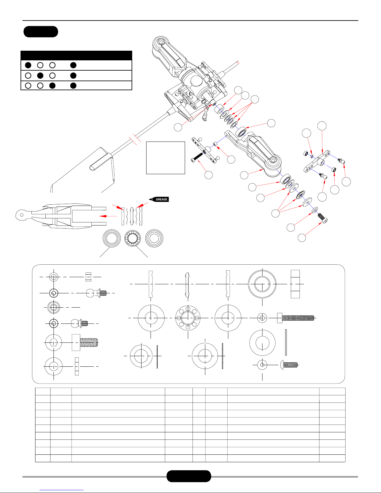
BELL MIXER RATIOS STYLE
BELL MIXER RATIOS STYLE
3D1:1.6
1:1.3
1:1
Using an available M3 screw, carefully form the
threads in the blade grip arm. Slide the M3x18
special socket shoulder screw through the bell
mixer arm from the flat side, add one M3x5x3
spacer and apply a drop of Slow Cyanoacrylate
glue or Epoxy glue to the end of the threads
before installing into the blade grip. Tighten the bolt until there is no end to
end movement, but do not
overtighten the bolt as
you can strip out the
hole. Make two assemblies.
THRUST BEARING INSTALLATION GUIDE
SIDE PROFILE - BLADE GRIP
LARGER ID TOWARDS THE GRIP
3D & SPORT
SPORT & FAI
GROOVES INSIDE
RECESSED CREVICE FACES MAIN SHAFT
7
Do not overtighten as you
can strip the
blade grip.
Press one M3x7 flanged ball
bearing into one side followed
by one M3x5 spacer and another
flanged bearing from the opposite side.
If the bearing is tight, lightly sand the bell
mixer and use Red threadlock to bond the
bearing in place. Install the CNLR1014 short
steel ball into the single hole side of the bell mixer
and install the CNLR1020 medium steel ball using
Blue threadlock. Install the medium steel ball according to the table to suit your flying preference. Use the
center hole for sport flying. Make two assemblies.
Radikal Gasser
There are two types of dampeners provided. The hard black plastic dampeners
(HI6520A) should only be used for hard 3D flying. Press in the head dampers
into the rotor head block. Lubricate the inside surface of each damper with light
oil. Press one M8x16 ball bearing into both ends of each main rotor blade grip.
Slide one M14 thrust washer against the bearing closest
to the main rotor blade. Make sure that the bearing and
the thrust washer are properly seated into the deep
end of the blade grip. If necessary use a socket
that matches the outside diameter of the
bearing and press into position. The 8x13
washer/spacer (#15) is used to adjust
tightness of the head. If the head is
binding after tightening the M5
bolt (#6), remove one or more
spacers from each side. Make
two assemblies.
16
1
2
9
8
7
6
3
5
4
13
12
17
14
11
15
10
HW6205
CNLR1020
CNBB0730
CNLR1014
CNM5X10CS
HW6182
8X13
HW6180A
No No.
Part # Part #
1
2
3
4
5
6
7
8
9
HI6189
HW6205
CNLR1020
CNBB0730
CNLR1014
CNM5X10CS
HW6180A
CNBB715T
HW6183
Enhanced Metal Bell Mixer Set
A
M3x5x3 Spacer
Stainless Ball, 3mm Thread, Medium
3x7x3 Ball Bearing
Stainless Ball, 3mm Thread, Short
M5x10 Socket Head Cap Screws
M5x10x1 Feathering Shaft with Center Ball
7x15x5 Blade Grip Thrust Ball Bearing
M5x8x15 Head Shim Set
Descriptio Description n
(垫圈)
(轴承)
(主桨控制臂)
(有头内六角螺丝)
(平面垫片)
(M3球头螺丝)
(M3球头螺丝)
(垫圈)
(止推轴承)
2
2
2
4
2
2
2
2
2
10
11
12
13
14
15
16
17
17
CNBB816
HI6184A
HW6205
CNM3x18CS
HW6182
HW6182
CNBB816
HI6181B
HI6181A
CNBB715T
HW6182
8X15
8x16x5 Bearing
NX Main Rotor Blade Grips
M3x5x3 Spacer
M3x18 Socket Head Cap Screws
8x15 Head Shim Set
8x13 Head Shim Set
8x16x5 Bearing
Hard Head Dampeners Black
Standard Head Dampeners Red
(轴承)
(垫圈)
(轴承)
(主旋翼夹片)
(平面垫片)
(平面垫片)
CNBB816
HW6183
M5X8X15
CNM3X6BHCS
(有头内六角螺丝)
M3X18CS
QtQt yy
4
2
2
2
2
6
4
2
2
Page 9
Page 10
HEAD ASSEMBLY (LT VERSION)
Radikal Gasser
BAG 1
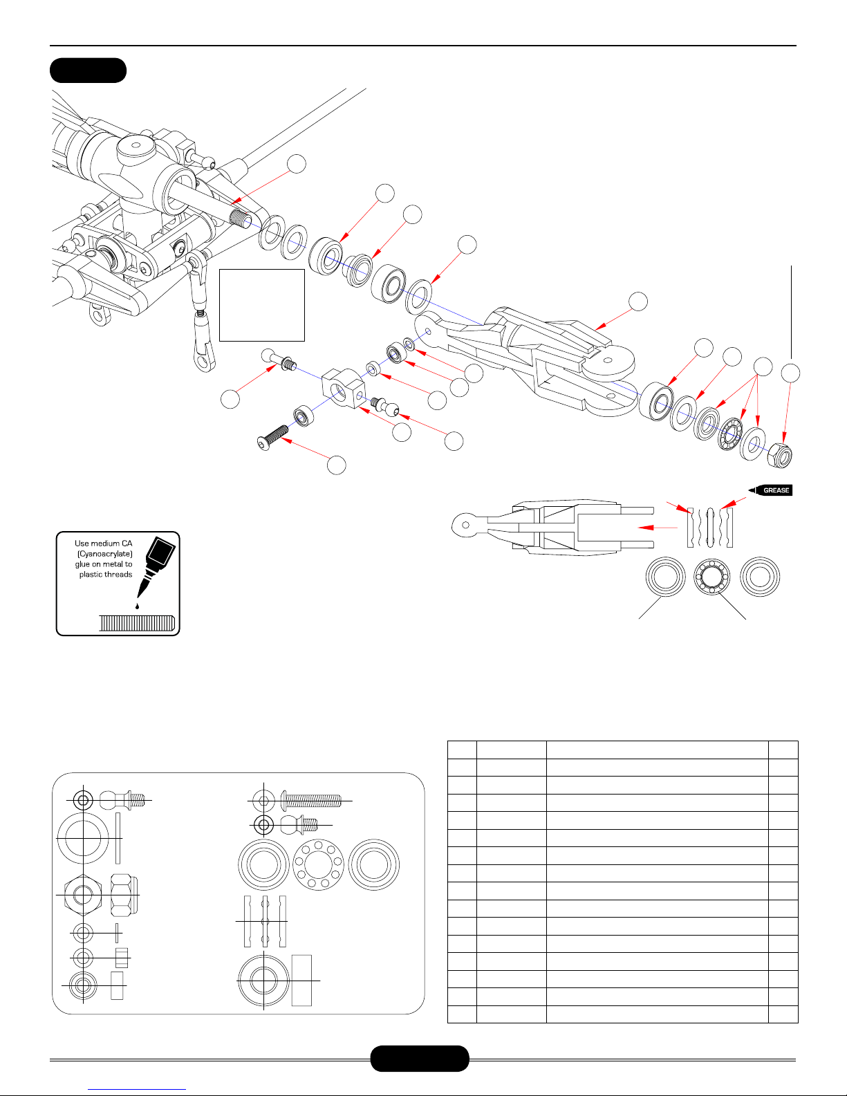
Do not overtighten as you
can strip the
blade grip.
Press one M3x7 ball bearing into one side followed by one
M3x5 spacer and another flanged
bearing from the opposite side. Install the
CNLR1014 short steel ball into one side of the
bell mixer and install the CNLR1020 medium steel
ball on the opposite side. Secure using
rylate glue. Make two assemblies.
15
Slow Cyanoac-
Press in the head dampers into the rotor head block. Lubricate the inside surface
of each damper with light oil. Press one M9X13 flat washer into the end of each
blade grip. If necessary use a socket that matches the diameter of the washer
and press into position. Then press in one M7X13 ball bearing into both ends
of each main rotor blade grip. Slide one M9 thrust washer against the bearing closest to the main rotor blade. Make sure that the bearing and the thrust
washer are properly seated into the deep end of the blade grip. If necessary use
8
a socket that matches the outside diameter of the bearing and press into posi-
tion. Torque down on the M5 locknut (#1) until snug making sure the grip
7
still turns without binding. If you tighten down too much, you will crush
6
the thrust bearings. If this happens, you will need to replace the
thrust bearings. Make two assemblies.
3
Do not apply threadlock to
the nylock nut!
5
4
3
9
2
1
10
11
13
12
14
THRUST BEARING INSTALLATION GUIDE
GROOVES INSIDE
C
M3 CNLR1016A
9x13x1
CNM5LOCK
3x5x0.5
3x5x3
CNBB0730
A
Using an available M3 screw, carefully form the
threads in the blade grip arm. Slide the M3x18
button head cap screw through the bell mixer arm
from the flat side, add one M3x5x0.5 micro washer
and apply a drop of Slow Cyanoacrylate glue to the
end of the threads before installing into the blade
grip. Tighten the bolt until there is no end to end
movement, but do not overtighten the bolt as you
can strip out the hole. Make two assemblies.
CNM3x14BHSC
M3 CNLR1014
CNBB1370T
CNBB1360
SIDE PROFILE - BLADE GRIP
LARGER ID TOWARDS THE GRIP
RECESSED CREVICE FACES MAIN SHAFT
Red dampener is used for normal flight #HI6181A. Black
dampeners are used for 3D flight #HI6181B.
No.
CNM5LOCK
1
CNBB1370T
2
CNM9X13FW
3
CNBB1370
4
HI3184
5
HW6180S
6
HI6181B
7
8
HW6180C
CNLR1003
9
10
CNBB0730
11
HW6205
12
CNLR1014
HI3189A
13
14
CNM3x14BHSC
15
CNLR1016A
Part #
M5 Locknut(M5 防松螺母)
Thrust Ball Bearing( 止推轴承)7x13x4.5
Washer(垫片)9x13x1
Bearing(滚珠轴承)7x13x4
Main Rotor Blade Grip(主桨夹片)
Spacer(铝套)
Dampener Rubber(橡胶圈)
7mm Feathering S haft( 横轴)
Washer(垫片)3x5x0.5
Bearing(滚珠轴承)3x7x3
Spacer(铁套)3x5x3
M3 Linkage Ball(M3 球头螺丝牙长3.5mm)
Bell Mixer Arm( 混控臂)
Buton Head Socket Screw( 圆头内六角螺丝)M3x14
M3 Long Linkage Ball(M3 球头螺丝球头12mm)
Description
Qty
2
2
8
4
2
2
2
1
2
4
2
2
2
2
2
Page 10
Page 11
HEAD ASSEMBLY (HD VERSION)
BAG 1
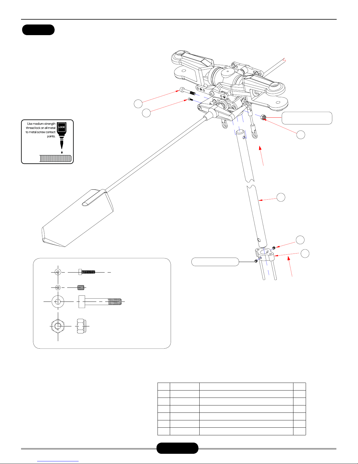
Slide the washout guide and the rotor head onto
the main shaft. Insert the M4x22 shoulder socket
cap screw through the rotor head hub and main
shaft and secure with one M4 locknut, torque
down the screw. Apply Medium threadlock to the
M2.5x8 socket cap screws and tighten into the
bottom of the rotor head block to clamp against
the main shaft, do not over torque. Position the
washout guide against the collar and align one
hole to the vertical slot in the rotor head. Apply
Medium threadlock to the M3x4 set screws and
evenly tighten set screws in place.
5
6
Radikal Gasser
Do not apply CA or
thread lock to lock nut!
4
M3x4
M4防松螺母
3
2
1
Do not over-tighten!
M2.5x8
M4x22
No.
Part #
1
HI6153
CNM3x4SS
2
3
HW6053A
4
CNM4LOCK
CNM4x22CS
5
CNM2.5x8CS
6
Page 11
Description
Aluminum Washout Guide( 剪型臂导柱)
M3x4 Socket Head Set Screw( 无头内六角螺丝)
10mm Main Shaft( 主轴)
M4 Lock-nut(M4 螺母)
M4x22 Cap Screws( 杯头内六角螺丝)
Cap Screw(杯头内六角螺丝)M2.5x8
Qty
1
2
1
1
1
2
Page 12
HEAD ASSEMBLY (LT VERSION)
BAG 1
Slide the washout guide and the rotor head onto
the main shaft. Insert the M3X18 shoulder
socket cap screw through the rotor head
hub and main shaft and secure with one
M3 locknut, torque down the screw. Apply
Medium threadlock to the M2.5x8 socket cap screws and tighten into the bottom of the rotor head block to clamp
against the main shaft, do not overtorque. Position the washout guide
against the collar and align one
hole to the vertical slot in the rotor
head. Apply Medium threadlock to
the M3x4 set screws and evenly
tighten set screws in place.
3
Do not apply CA or
thread lock to lock nut
Radikal Gasser
1
Do not over-tighten!
2
4
6
5
CNM3x4SS
CNM2.5x8CS
CNM3x18CS
CNM3LOCK
Page 12
No.
1
2
3
4
5
6
Part #
CNM2.5x8CS
CNM3x18CS
CNM3LOCK
HW3053B
CNM3x4SS
HI6153
Description
Cap Screw(杯头内六角螺丝)M2.5x8
Cap Screw(杯头内六角螺丝)M3x18
M3 Locknut(防松螺母)
Main Shaft(主旋翼轴)
Set Screw(无头内六角螺丝)M3x4
CNC Washout Guide(剪型臂滑座)
Qty
2
1
1
1
2
1
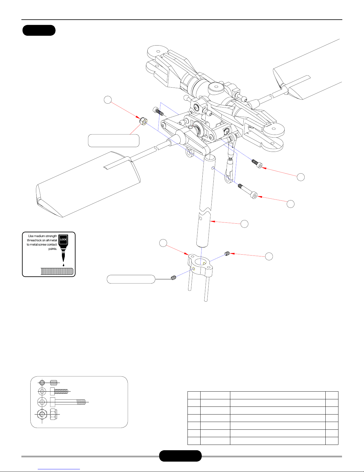
Page 13
WASHOUT AND SWASHPLATE
Radikal Gasser
BAG 1
1
M3 L=7.8MM CNLR1014
2
3
M3X5X3 HW6205
4
5
7
CNBB0730
6
8
9
10
M10x12x5 HI3152C
M3x5x0.5 CNLR1003
CNM3x16BHCS
M3 L=18MM
Ø2x12
Comes pre-assembled
It is up to you to determine whether this assembly is correct. Please make
sure to check it prior to installation.
No.
HI3152A
1
CNLR1014
2
HW6205
3
CNBB0730
4
HI3152A
5
HI3152A
6
7
HI3152C
CNLR1003
8
9
CNM3x16BHCS
CNLR1014
10
CNLR1021
11
12
HW6146C
Part #
Washout Set (10mm) (
M3 Ball Link(M3球头螺丝)
3x5x3 Bellcrank Spacer(铜套)
3x7x3 Bearing(轴承)
Radius Link w/ Pin(插销)
Radius Link w/ Pin(三角控制臂)
Washout Set (控制臂固定座)
3x5x0.5 Micro Washer(
M3x16 Button Head Cap Screws(
M3 Ball Link(M3球头螺丝)
M3 Ball Link L=18MM(M3球头螺丝)
Radikal Swashplate(十字盘)
Description
摆臂)
)
垫圈
圆头内六角螺丝
Qty
2
2
2
4
2
2
1
2
)
2
4
2
1
Starting with the inside race, apply Medium threadlock to the silver steel balls and attach them across
from each other. The balls need to be started by
hand then tightened with an M2.0 hex key. Insert the
other two steel balls across from each other using
Medium threadlock. Install three long steel balls on
the outer arms using Slow Cyanoacrylate glue.
10
Page 13
11
12
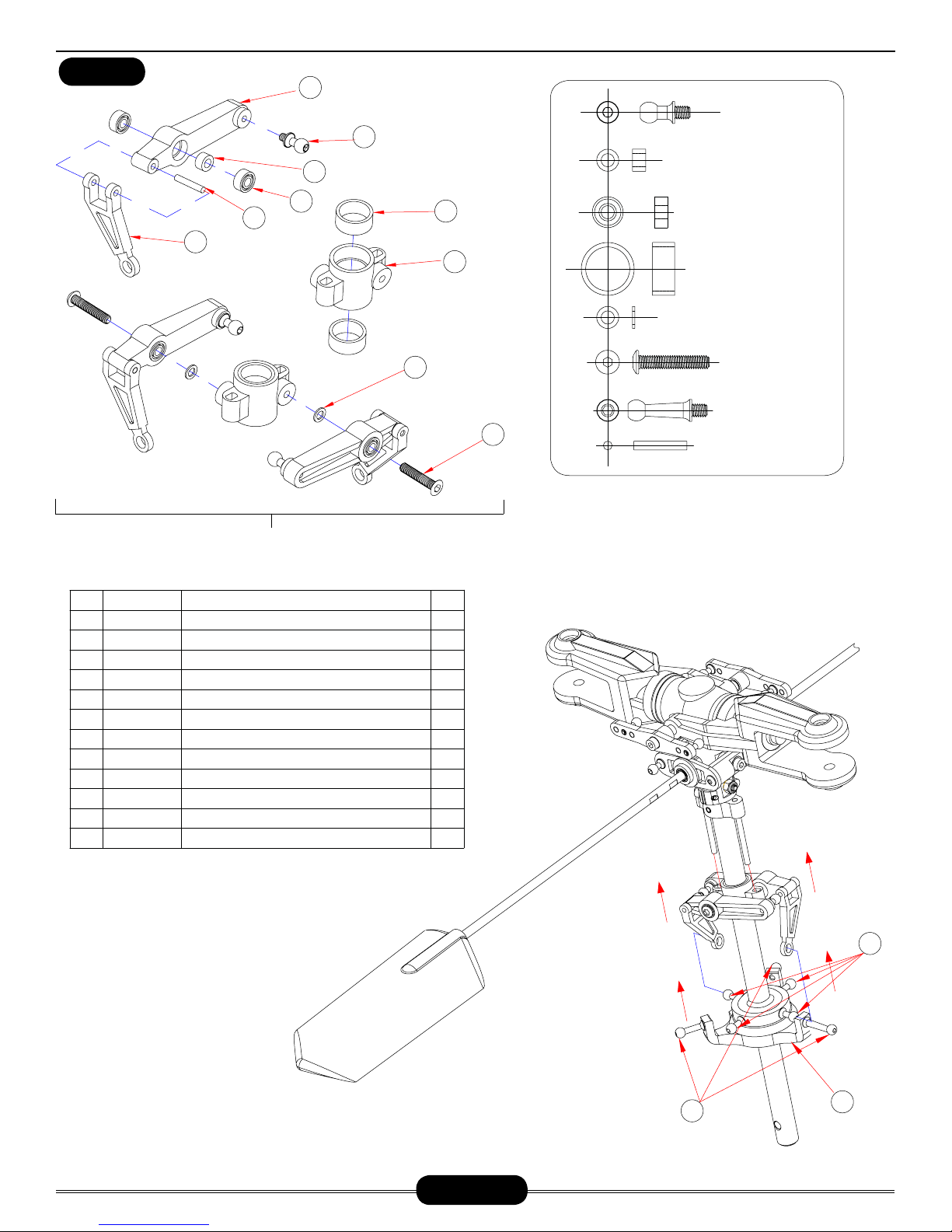
Page 14

WASHOUT AND SWASHPLATE (LT VERSION)
BAG 1
Radikal Gasser
3
4
8
2
1
10
11
12
No.
HI3152A
1
CNLR1014
2
HW6205
3
CNBB0730
4
HI3152A
5
HI3152A
6
7
HI3152C
CNLR1003
8
9
CNM3x16BHCS
CNLR1014
10
CNLR1021
11
12
HW6146C
Part #
5
6
9
Comes pre-assembled
It is up to you to determine whether this assembly is correct. Please make sure to check it
prior to installation.
Starting with the inside race, apply Medium threadlock to the silver steel balls and attach
them across from each other. The balls need to be started by hand then tightened with an
M2.0 hex key. Insert the other two steel balls across from each other using Medium threadlock. Install three long steel balls on the outer arms using Slow Cyanoacrylate glue.
M3 L=7.8MM CNLR1014
M3X5X3 HW6205
Washout Set (10mm) (
M3 Ball Link(M3球头螺丝)
3x5x3 Bellcrank Spacer(铜套)
3x7x3 Bearing(轴承)
Radius Link w/ Pin(插销)
Radius Link w/ Pin(三角控制臂)
Washout Set (控制臂固定座)
3x5x0.5 Micro Washer(
M3x16 Button Head Cap Screws(
M3 Ball Link(M3球头螺丝)
M3 Ball Link L=18MM(M3球头螺丝)
Radikal Swashplate(十字盘)
Description
摆臂)
)
垫圈
圆头内六角螺丝
Qty
2
2
2
4
2
2
1
2
)
2
4
2
1
CNBB0730
M10x12x5 HI3152C
M3x5x0.5 CNLR1003
CNM3x16BHCS
M3 L=18MM
Ø2x12
7
Page 14
Page 15

HEAD PUSHROD LENGTHS (HD VERSION)
BAG 1
Radikal Gasser
A
25.5
14
1
2
3
B
4
C
5
HELPFUL TOOL:
A
PART# CN2219A: BALL LINK
43
25
B
DRAWN TO A SCALE OF
1-TO-1. YOU CAN MATCH
YOUR LINKS UP TO THIS
PAGE FOR PROPER MEASUREMENTS.
EASY DRIVER
NOTICE SIZE OF HOLES ON BALL LINKS
95
75
C
HEL PFUL TOOL
No.
Part #
1
2
3
4
5
HI6145
HW6192A
HI6145
HW6192A
HW6192A
Ball Link Set (26 Long, 4 Short)(
Pushrod Set( 连杆)
Ball Link Set (26 Long, 4 Short)(球头连接杆 )
Pushrod Set( 连杆)
Pushrod Set( 连杆)
THE SIDE WITH THE SMALLER HOLE
SHOULD FACE OUTWARDS
Description
球头连接杆
)
Qty
4
2
8
2
2
PART# CN2255: CONTROL ROD SETUP GAUGE
Page 15
Page 16

HEAD PUSHROD LENGTHS (LT VERSION)
BAG 1
NOTICE SIZE OF HOLES ON BALL LINKS
THE SIDE WITH THE SMALLER HOLE
SHOULD FACE OUTWARDS
25
14
Radikal Gasser
43
5
4
A
HELPFUL TOOL:
PART# CN2219A: BALL LINK
EASY DRIVER
HEL PFUL TOOL
DRAWN TO A SCALE OF
1-TO-1. YOU CAN MATCH
YOUR LINKS UP TO THIS
PAGE FOR PROPER MEASUREMENTS.
25
94
75
C
3
2
1
B
PART# CN2255: CONTROL ROD SETUP GAUGE
Page 16
No.
1
2
3
4
5
Part #
HI6145
HW3192A
HW6192
HI6145
HW6192
Description
Ball Link(塑胶球头连接头)
Pushrod(连杆)L=80MM
Pushrod(连杆)L=25MM
Short Ball Link( 短塑胶球头连接头)
Pushrod(连杆)L=14MM
Qty
8
2
2
4
2
Page 17

SKELETAL SUPPORT BRACES
This bearing is already pressed
6
into the bearing block.
5
Radikal Gasser
BAG 2
4
9
COMES
PRE-ASSEMBLED
3
8
7
10
11
2
1
CNM2.5x6FHCS
CNM3x10FHCS
CNM3x12BHCS
Ø2X24
CNBB1022
Page 17
12
No.
Part #
1
HW6117G20
CNM3x10FHCS
2
HW6119
3
HW6042G
4
5
CNM3x12BHCS
CNBB1022
6
HI6032G
7
HI6032G
8
9
HI6032G
10
CNM2.5x6FHCS
HI6113
11
HW6113S
12
Landing Gear Frame( 引擎座底板)
Flush Head Cap Screws( 斜头内六角螺丝)M3x10
Box Frame Support( 机身加强支架)
Lower Main Shaft Bearing Block(主轴下轴承座)
Button Head Cap Screw( 圆头内六角螺丝)M3x12
Bearing(滚珠轴承
A-Arm Base(A 型控制臂座
Pin(插销)Ø2x24
A-Arm(A型控制臂)
Flush Head Cap Screws( 斜头内六角螺丝
Electronics Plate(电子点火固定板
Aluminum Post( 铝柱)
If you have carbon fiber frames, just add a “C” to the end of the frame
part number.
Description
) 10X22X5
)
Qty
1
2
2
1
2
1
1
1
1
)M2.5x6
)
2
1
1
Page 18

REAR SIDEFRAME (LEFT)
BAG 2
Radikal Gasser
Flanged bearing is already
pressed into frames. Make sure
the flange is facing inwards.
This bearing is already pressed
into the bearing block.
3
4
Dry fit the electronics tray built from
the previous page into the left rear
sideframe prior to mounting onto
the skeletal support frame assembly.
Once done, install the M3x8 button
head cap screws as shown. Apply
medium threadlock to all the screws.
1
5
6
2
CNBB1019
CNM3x8BHCS
No.
1
2
3
4
5
6
Part #
HI6116L
CNM3x8BHCS
CNBB1019
HW6042GU
CNM3x6BHCS
CNBB1019
Main Frames( 左右后侧板)
Button Head Cap Screw( 圆头内六角螺丝)M3x8
Bearing(滚珠轴承)10x19x5
Upper Bearing Block( 主轴上轴承座)
Button Head Cap Screw( 圆头内六角螺丝)M3x6
Bearing(滚珠轴承)10x19x5
Description
If you have carbon fiber frames, just add a “C” to the end of the frame
part number.
Page 18
Qty
2
8
2
1
1
1
Page 19

FUEL TANK
BAG 2
Pay close attention when assembling the fuel tank.
The vent tube must be bent and facing upwards when
installed into the rubber stopper. There are 3 holes
on the rubber stopper but notice only 2 are through
holes. Cut the fuel line and attach the clunk to the
line. Then attach the fuel line to the short brass tube.
When cutting the fuel line, make sure you have enough
slack in the fuel line so the clunk can reach all corners
of the fuel tank. After installing the shorter brass tube
with the fuel line, install the vent tube. Make sure the
vent tube is positioned to point upwards in the fuel
tank. Once you have everything positioned, slowly turn
the M3.5x24 Phillips screw so that you barely grab
the end of the small cap (#4). Once you insert the
fuel tubing assembly into the tank, it will be very difficult to get this small cap out if you happen to drop
it within the fuel tank. Making sure you still have the
small cap (#4) attached to the fuel tubing assembly,
push the fuel tubing assembly into the tank and start
tightening the Phillips screw. This will pull the small
cap (#4) closer to the large cap (#2) and expand the
rubber stopper. Once tightened, gently tug on the assembly to make sure it is properly installed. It should
not come out of the fuel tank.
Bend one of the longer brass tubes into
this shape. This will
be the vent tube.
Radikal Gasser
9
7
8
6
5
4
3
CNM3.5x24ST
No.
1
2
3
4
5
6
7
8
9
Page 19
1
Part #
HI6139
HI6139
HI6139
HI6139
HI6139
HI6139
HI6139
HI6139
HI6139
2
HI6139A: Fuel Tank Fittings Set Only
Description
Tapping Screw( 十字紧固螺丝)M3.5x24
Large Cap(油箱盖)
Rubber Stoper( 油箱塞)
Small Cap(油箱塞固定座)
Long Tube-straight( 长直铜油管)
Pickup Tube-straight(短直铜油管)
Fuel Tubing( 塑胶油管)
Fuel Tank Set( 吸油嘴)
Fuel Tank(油箱)
Qty
1
1
1
1
1
1
1
1
1
Page 20

REAR SIDEFRAME (RIGHT)
BAG 2
12
When installing the elevator bellcrank, make sure to apply medium
CA to the M3x12 button head cap screw.
Radikal Gasser
2
11
8
7
2
3
1
9
5
10
6
Assemble the aileron bellcranks by
4
first pressing in the 3x7x3 bearing
followed by the 3x5x7.5 spacer. Install the remaining bearing along with
the metal balls. It is easier to thread
the M3 linkage balls into the plastic
bell cranks if you use an available M3
screw to make threads. Apply medium CA to the linkage balls. Once
you have the aileron bell cranks built,
install the right rear frame and apply medium threadlock to the M3x8
button head screws and tighten onto
the skeletal support frame. Apply
medium threadlock to the M3x25
button head cap screws and install
the aileron bell cranks onto the aluminum post.
14
13
CNBB812F
3x8x3.5
CNM3x8BHCS
CNLR1014
CNBB0730
CNM3x12BHCS
CNM3x25BHCS
C
A
No.
CNM3x25BHCS
1
CNLR1014
2
CNBB0730
3
4
HI6031G
5
HI6031G
HI6031G
6
HW6125B
7
8
CNBB812F
CNM3x8BHCS
9
10
HI6031S
CNM3x12BHCS
11
12
HI6032GB
HI6139B
13
HI6116R
14
Part #
Button Head Cap Screw( 圆头内六角螺丝)M3x25
M3 Linkage Ball( 球头螺丝
Bearing(滚珠轴承)3x7x3
Bell Crank(左右控制臂)
Bellcrank Spacer( 垫片)3x5x7.5
Bellcrank Spacer( 垫片)3x8x3.5
Canopy Standoff( 机头罩支架)
Elevator Lever Flange Bearing( 带边滚珠轴承)
Button Head Cap Screw( 圆头内六角螺丝)M3x8
Aluminum Post( 铝柱)
Button Head Cap Screw( 圆头内六角螺丝)M3x12
Elevator Bellcrank(
Fuel Tank Isolators(油箱橡胶垫)
Right Rear Frame (
Description
)
控制臂)
左右后侧板
Qty
2
8
4
2
2
2
2
2
10
1
2
1
2
)
1
If you have carbon fiber frames, just add a “C” to the end of the frame
part number.
Page 20
Page 21

CLUTCHBELL ASSEMBLY
BAG 2
Radikal Gasser
1
4
2
CNBB1015
CNM4x4SS
3
CNBB513
6
7
8
9
5
CNBB1524
CNBB511
4
The Radikal uses the regular starting shaft and hex coupler as to align
the clutch to the clutchbell. Clean both the starting shaft and the inside
race of the bearing inside the clutchbell and the inside race of the top
starting shaft bearing. Apply a small amount of Red threadlock positioned just above where the bottom clutchbell bearing will sit on the
starting shaft. Slide the starting shaft up through the bearing blocks.
Apply a small amount of medium threadlock to the top of the starting
shaft and slide the hex coupler in place aligning the flat spot with one of
the holes. Apply medium threadlock to the two M4x4 set screws and
tighten in place.
10
11
Clean the top of the pinion gear and the inside surfaces of both the upper
and lower bearings inside the clutch shaft bearing block using alcohol.
Apply a small amount of Red threadlock to the top edge of the clutch gear
where it will contact the bearing. Press the bearing block in place, firmly
seating the bearing against the top of the pinion gear.
Page 21
No.
1
2
3
4
5
6
7
7
8
9
10
11
Part #
CNM4x4SS
HW6002
CNBB513
HW6007G
HW6007GS
CNBB1015
HW6043A
HW6043B
CNBB1524
HW6013G
CNBB511
HW6006
Description
Set Screw(无头内六角螺丝)M4x4
6mm Hex Coupler(
Bearing(滚珠轴承)5x13x4
Bearing Block( 轴承座)
Long Hex Spacers( 六角铝柱)L=52MM
Bearing(滚珠轴承)10x15x4
Alloy Drive Gear 14T For LT Version(合金传动齿轮)
Alloy Drive Gear 16T For HD Version(合金传动齿轮)
Bearing(滚珠轴承)15x24x5
Clutch Bell Assembly( 离合器罩)
Bearing(滚珠轴承)5x11x4
Starting Shaft( 启动轴)
六角启动头)
Qty
2
1
1
2
4
1
1
1
1
1
1
1
Page 22

ZENOAH 20CC ENGINE PREPARATION
Radikal Gasser
It is not so apparent how the propeller hub is attached to the engine.
A 13mm lock nut is supplied in the kit to aid in the removal of the
propeller hub.
Install the supplied 13mm locknut and tighten down onto the shaft. Tighten down on the top lock nut while applying opposite force (un-
First undo the nut and remove the propeller washer. Screw down
the original nut onto the stud followed by the locknut.
screwing) to the second nut using the Zenoah supplied wrench.
This will allow you to lock the nuts together.
Because you have no use for the propeller hub, you can use a wrench
or vice to grab onto the hub while trying to undo the stud. Grabbing
onto this aluminum hub may damage the hub but it’s of no use in this
build. Once this stud is loosened, you can remove the propeller hub.
Remove the stud and hand tighten it a few threads into the crank.
With the propeller hub still in the vice, gently tap on the head of the
stud with a hammer while supporting the engine with your other
hand. This will loosen the hub from the crank shaft.
MAKE SURE NOT TO LOSE THIS KEY! It is very important to retain this
key for the following steps. Without this key, you cannot mount your fan
and clutch assembly. After you have removed the hub, remove the bottom plate and flush head cap screws. Set these aside as you will not be
needing them for the rest of the build.
Page 22
Page 23

CLUTCHSHOE AND FAN ASSEMBLY
BAG 3
Radikal Gasser
1
Bearing is pre-installed
2
7
Install the clutch temporarily and do a dry
fitment into your clutch bell that is mounted
to your frames. If your clutch shoe is sitting
outside the clutch bell when your engine is
mounted to your frames, you will most likely
need 2 clutch shims.
15
16
13
17
Do not overtighten
3
8
4
5
6
9
10
11
The hex starting system is a regular replacement part and will wear due to normal use. The pull start option is a better alternative to starting the helicopter.
12
You can use a pull start for the first start
of the day. Afterwards using a heavy
duty electric starter is possible.
Do not overtighten
14
6.5x13x1
CNM2.5x8CS
CNM4x10FHCS
CNM3x6FHCS
6.5x13x1
CNM6x16CS
CNLR1018
CNM3x4SS
Lay the cooling fan shroud mount plate onto
the face of the engine with the straight edge
towards the cylinder head and the access
hole on the muffler side.
No.
Part #
HI6020G
1
CN2263K
2
HW6011G
3
HW6011GS
4
CNM6x16CS
5
CNM6.5X13FW
6
HI6009GBKH
7
8
HI6009GBK
9
HI6009GM
10
CNM3x6FHCS
11
HW6118W
12
CNM2.5x8CS
13
CNM4x10FHCS
14
ZENE20EIN OT INCLUDED
15
HW6192B
16
CNM3x4SS
17
CNLR1018
Plastic Cooling Shroud( 风扇罩)
Auto Hub Assembly(8mm)( 单向轴承)
Clutch Shoe(离合器)
Clutch Shim(垫片 )20x22x0.5
Cap Screw(杯头内六角螺丝)M6x16
Washer(垫片)6.5x13x1
Cooling Fan Hub(风扇座)
Cooling Fan(风扇)
Magnet(磁铁)
Flush Head Cap Screws( 斜头内六角螺丝)M3x6
Cooling Shroud Mount Plate( 挡风板)
Cap Screw(杯头内六角螺丝)M2.5x8
Flush Head Cap Screws( 斜头内六角螺丝)M4x10
Engine(引擎)
Carburetor Arm( 化油器控制臂)
Set Screw(无头内六角螺丝)M3X4
Ultra Short Steel Ball( 球头螺丝)
Description
Qty
1
1
1
1
1
1
1
1
2
4
1
3
4
1
1
1
1
Page 23
Page 24

EFI PICK UP
BAG 2
Radikal Gasser
3
4
5
1
Mount the plate onto the engine first and
tighten the M4x10 Flush Head Cap Screws.
After you have installed the plate, then install
the sensor. The sensor can be adjusted
slightly to advance or retard timing.
2
6
CNM4x10FHCS
CNM2.5x8CS
2.5x4x4
Page 24
No.
1
HI6010
Not Included
2
CNM4x10FHCS
3
4
HI6010
5
CNLR1003
6
CNM2.5x8CS
Part #
Description
Sensor Adaptor Board(
Sensor(感应器)
Flush Head Cap Screws( 斜头内六角螺丝)M4x10
Copper Sleeve( 铜套)2.5x4x4
Washer(垫片)3x5x0.5
Cap Screw(杯头内六角螺丝)M2.5x8
感应器固定板)
Qty
1
1
2
2
2
2
Page 25

ELECTRONICS TRAYS
BAG 3
Radikal Gasser
5
1
2
4
3
Start by installing the four M2.5x6 flush head cap screws into
the lower electronics tray by using medium threadlock. Use
the M3x30 Phillips tapping screws to mount the canopy hook.
6
Do not overtighten this as you can strip the plastic.
Next apply medium threadlock to the remaining four M2.5x6
flush head cap screws and install them into the upper electronics tray. Tighten to the frame support bars.
7
No.
CNM2.5x6FHCS
1
HW6113A
2
HW6113AS
3
4
HI6113B
5
CNM3x30ST
6
HI3129
HI3129
7
Part #
Flush Head Cap Screws( 斜头内六角螺丝)M2.5x6
Upper Electronics Tray( 变速器固定板)
Frame Support Bar( 铝柱)
Lower Electronics Tray( 接收机固定板)
M3x30 Phillips Tapping Screws( 自攻螺丝)
Canopy Mount Spacer ( 机头罩扣座)
Canopy Mount Hook( 机头罩扣)
Description
If you have carbon fiber frames, just add a “C” to the end of the frame
part number.
CNM2.5x6FHCS
CNM3x30ST
Qty
8
1
4
1
2
1
1
Page 25
Page 26

FRONT SIDE FRAMES
BAG 3
1
2
Radikal Gasser
Make sure when fitting the electronics trays that you have a complete mating with the upper side frames. If the keys do not fit into
the slots on the upper side frames and you tighten down on the
screws, your frame will be crooked.
Apply medium threadlock to the eight M3x8 button head cap
screws and tighten down.
CNM3x8BHCS
No.
1
2
Part #
HI6115GL
CNM3x8BHCS
Front Frames ( 前侧板)
Button Head Cap Screw( 圆头内六角螺丝)M3x8
Description
If you have carbon fiber frames, just add a “C” to the end of the frame
part number.
Page 26
Qty
2
8
Page 27

MOUNTING MOTOR
BAG 2
Radikal Gasser
1
Loosely fit the CNM4X10 cap screws that hold the
engine on the plate. Then line up the bearing assembly
in the upper portion of the frames. Keep this loose for
2
now until you are ready to mesh the pinion gear with
the main gear.
CNM3x8BHCS
1
Page 27
No.
1
2
Part #
CNM3x8BHCS
CNM4x10CS
CNM4x10CS
Description
Button Head Cap Screw( 圆头内六角螺丝)M3x8
Cap Screw(杯头内六角螺丝)M4x10
Qty
6
4
Page 28

ATTACHING FRONT FRAME ASSEMBLY
BAG 2
Radikal Gasser
When mounting the front frames to the rear frames,
make sure the keyed split matches up properly
prior to tightening the eight M3x8 button head cap
screws. This is very important as you can warp the
frames if it’s not set in place when tightening down.
Prior to installing the eight M3x8 button head cap
screws, be sure to use medium threadlock.
1
CNM3x8BHCS
Page 28
No.
CNM3x8BHCS
1
Part #
Description
Button Head Cap Screw( 圆头内六角螺丝)M3x8
Qty
8
Page 29

LANDING GEAR
LANDING GEAR PACKAGE
Radikal Gasser
3x8x1
CNM3x4SS
CNM3x16CS
1
4
3
5
2
6
Install the landing skids onto the landing struts one
side at a time. After installing the landing skids,
position, the landing struts on the skids so that
they match up with the mounting positions on the
frames. Place the washers onto the M3x16 cap
screws and then apply medium threadlock. Install
the screws through the landing struts and tighten
onto the frames. Turn the landing skids so that the
curve towards the front is facing straight up. Make
sure you have approximately 28mm of skid showing
out the back. Install the four M3x4 set screws to
lock the skids into place. Do not tighten these too
much as you can crack the plastic struts. Lastly,
install the landing skid stoppers.
Page 29
No.
1
2
3
4
5
6
Part #
HI3122A
HW3123A
CNM3x16CS
CNM3x8FW
CNM3x4SS
HW3123A
Description
Plastic Struts( 脚架)
Aluminum Skids( 脚架弯管)
Cap Screw(杯头内六角螺丝)M3x16
M3x8x1 Flat Washers( 垫片)
Set Screw(无头内六角螺丝)M3x4
Landing Skids Stopper(脚架塞)
Qty
2
2
4
4
4
4
Page 30

MAIN GEAR ASSEMBLY
BAG 3
Radikal Gasser
Apply medium threadlock to the four
M3x6 flush head cap screws and install
through the tail drive gear tightening
onto the driven tail hub. Apply medium
threadlock to the six M3x8 flush head
cap screws and install onto the main
gear with the auto-rotation one way
1
bearing. Make sure the flush head cap
screws are installed onto the concave
beveled side of the screw holes on the
main gear.
2
3
Be sure to clean the inside and outside of the main shaft
sleeve with alcohol prior to installation.
4
5
6
For the roller bearings, we recommend a very light oil. The oil MUSTNOT attack/break down plastic as
this could damage the cage in the
one-way bearing. Prior to applying oil,
7
make sure to clean the roller bearings with a cotton swab making sure
there is no debris in the bearings.
CNM3x6FHCS
CNM3x8FHCS
Page 30
No.
1
2
3
4
5
6
7
Part #
HW6057A
HI6057
CNM3x6FHCS
HW6057C
CNM3x8FHCS
HI6057C
HW6057D
Description
Driven Tail Hub( 传动主齿轮座)
Tail Drive Gear(传动主齿轮)
Flush Head Cap Screws( 斜头内六角螺丝)M3x6
Main Shaft Sleeve(主齿轮铁套
Flush Head Cap Screws( 斜头内六角螺丝
Main Gear 90T
One-way Bearing( 单向轴承座
(斜齿轮
)
)M3x8
)
)
Qty
1
1
4
1
6
1
1
Page 31

ATTACHING HEAD AND MAIN GEAR
Radikal Gasser
BAG 3
1
CNM4x4SS
CNM2.5x8CS
10x18x1
Ø3x23.7
3
2
4
6
5
4
Apply grease to the thrust bearing. Place the Main Gear assembly into
the frames. Insert the main shaft with head assembly through the bearing blocks while lining up the thrust bearing, and mast stopper while going through the Main Gear assembly. Line up the whole in the Main Shaft
with the hole on the Driven Tail Hub. With the help of needle nose pliers
or hemostats, place the Pin (#5) through while making sure you have it
going through the Main Shaft. Install the 2 M4x4 set screws making
sure you have them evenly threaded on both sides. When installing the
Mast Stopper (#3), make sure it is pushed up to the top prior to tightening the M2.5x8 Cap Screw.
CNBB1018T
No.
1
2
3
4
5
6
Page 31
Material No.
CNBB1018T
CNM2.5X8CS
HW6054
CNM4x4SS
HW6057AS
HW6057DS
Description
Thrust Bearing( 止推轴承)10x18x5.5
Cap Screw(杯头内六角螺丝)M2.5x8
Mast Stopper( 主轴限位块)
Set Screw(无头内六角螺丝)M4x4
Pin(
插销)Ø3x23.7
Copper Washer( 铜垫片)10x18x1
Qty
1
1
1
2
1
1
Page 32

TAIL BOOM COMPONENTS
BAG 4
Radikal Gasser
20
When installing all the hardware onto the boom, make
sure you do so prior to installing the tail gearbox. Otherwise you will not be able to once your tail gearbox is
mounted. Do not apply the zip ties until the very
end when you are sure of the positions of
the tail control rod guides. When build-
17
ing the tail control rod, make sure
to place the control rod through the
guides prior to installing the ends.
Do not install the horizontal fin until
you have tightened the tail boom supports and horizontal fin mount. It is
best to install the horizontal fin to-
16
wards the end of your build.
1
18
19
14
21
13
11
12
10
9
15
CNM3x10CS
CNLR1013
M2 CNLR1018
CNM2x8PH
CNM3x8ST
CNM3x8BHCS
M3 CNM3LOCK
INCLUDED
CNM2.3x12ST
CNM3x14BHCS
8
2
3
4
5
6
7
No.
HI6080B
1
CNM3x10CS
2
NOT INCLUDED
3
NOT INCLUDED
4
NOT INCLUDED
5
6
HI3205A
CNM2.3x12ST
7
8
CNLR1013
CNLR1018
9
HI6106B
10
11
HI6068A
12
CNM3x14BHCS
CNE543
13
CNM2x8PH
14
CNE543
15
16
HW3202C
17
CNM3x8ST
HI6106B
18
19
CNM3LOCK
CNM3x8BHCS
20
HI6067GH
21
Part #
Tail Servo Mount( 尾翼伺服机座)
Cap Screw(杯头内六角螺丝)M3x10
Servo(伺服机)
Copper Rivet(铜铆钉)
Anti-Vibration Pad(防震胶垫)
Servo Mounting Plate( 伺服机固定板)
Self Tapping Screws( 尖尾自攻螺丝)M2.3x12
Steel Ball 2mm Thread(m2 球头螺丝)
M2 Hex Nuts(m2 六角螺母)
Adjustable Tail Guides( 尾拉杆固定座)
Horizontal Fin Mount( 水平翼固定座)
Button Head Screw( 圆头内六角螺丝)M3x14
Tail Boom Support Strut End( 连杆头)
Phillips Screw( 圆头十字螺丝)M2x8
Tail Control Rod( 尾舵控制连杆)
Tail Boom Support Struts( 尾支撑杆)
Self Tapping Screws( 尖尾自攻螺丝)M3x8
Zip Tie( 扎带)
M3 Lockmut(M3 螺母)
Button Head Screw( 圆头内六角螺丝)M3x8
Horizontal Fin( 水平翼)
Description
Qty
2
2
2
2
2
2
4
1
2
1
1
1
2
2
1
2
2
1
1
2
1
If you have carbon fiber frames, just add a “C” to the end of the frame
part number.
Page 32
Page 33

TAIL GEARBOX
BAG 4
15
Make sure to install
this first before
clamping the tail
gearbox together.
16
19
20
The taller lip should
face outwards.
14
21
17
13
12
22
Radikal Gasser
When pressing the bearing retainers into the tail gear box
plate, make sure you are pressing it into the correct side. The
left and right side are different. If you do not do this, it will be
difficult to remove this pieces once it’s pressed in.
11
10
9
8
7
6
5
24
4
When clamping the tail gearbox to the boom, make sure
the tail boom retainers are
properly keyed to the slots on
the tail boom. After clamping,
approximately 3mm of the tail
boom should be visible.
CNM3x6BHCS
CNM3x8BHCS
CNM2.5x8CS
5x7x3.5
5x7x6.5
M3 CNM3LOCK
Ø2x12
CNBB1350
L=26MM
Ø5x27
18
CNM3x40CS
5x7x12
CNBB38
CNM3x4SS
3
23
2
1
No.
HI6067GV
1
2
3
CNM2.5x8CS
4
HI6078H
5
6
CNBB1350
7
CNE529
8
CNE529
9
10
11
HW6078TP
12
HW6073B
13
14
15
CNM3LOCK
16
17
18
19
CNM3x6BHCS
HI6078P
20
HI6078P
21
22
HI6078P
HI6631
23
CNM3x4SS
24
Part #
CNM3x8BHCS
CNM3x40CS
HW6073B
HW6073B
HI6078H
HW6078TP
HI6078B
HI6078B
HI6078B
Vertical Fin(垂直翼)
Button Head Screw( 圆头内六角螺丝)M3x8
Cap Screw(杯头内六角螺丝)M3x40
Cap Screw(杯头内六角螺丝)M2.5x8
Bearing Units( 轴承套)
Bearing(滚珠轴承)5x13x4
Spacer Units(铝套)M5x7x6.5
Lock Pin(插销)Ø2x12
Tail Gear(尾皮带轮)
Tail Output Shaft(尾翼轴)
Threaded Spacer( 铝柱)Ø5x27
Spacer Units(铝套)5x7x3.5
Tail Gearbox Bearing Retainer(双轴承套)
Tail Gear Box Plate-Right(尾齿轮箱夹片)
M3 Locknut(M3螺母)
Tail Pitch Bellcrank "L" Arm(L臂)
Tail Gear Box( 尾齿轮箱)
Short Threaded Hex Spacer( 六角铝柱)L=26mm
Button Head Screw( 圆头内六角螺丝)M3x6
Spacer ( 铝套)3x5x12
Bearing(滚珠轴承)3x8x3
Tail Belt Tensioner Pulley( 皮带压轮)
Tail Belt(皮带)
Set Screw(无头内六角螺丝)M3x4
Description
Qty
1
8
1
1
1
3
1
1
1
1
1
1
1
1
1
1
2
4
1
2
1
1
1
1
If you have carbon fiber frames, just add a “C” to the end of the frame
part number.
Page 33
Page 34

TAIL ROTOR ASSEMBLY
BAG 4
Radikal Gasser
Comes pre-assembled.
13
12
10
Face flat side of
tail hub towards
the gear box.
Starting with the tail rotor assembly, press the
4x10x4 (#11) bearing into the tail blade grip. Grease
the thrust bearings prior to installation. Making sure
the open ball end is facing the tail hub, place the thrust
bearing assembly into the tail blade grip followed by
the 3x5x0.5 micro washer. Install the 3x9x2.5 (#4)
bearing and then tighten the assembly with the M3
locknut.
No.
Part #
1
HI6099A
HW6204
2
CNM3LOCK
3
4
CNBB0930
CNLR1003
5
6
CNBB49T
7
CNM3x16BHCS
8
CNM3x18CS
HI6096A
9
10
CNLR1013
11
CNBB410
12
HW3098A
13
CNM3x4SS
14
HI3087B
CNLR1019
15
16
CNBB37F
17
18
HI6102
HI6102
Tail Rotor Blades(尾旋翼)
Micro Washer( 垫片)3x10x1.5
M3 Locknut(M3 螺母)
Bearing(滚珠轴承)3x9x2.5
Micro Washer( 垫片)3x5x0.5
Thrust Ball(止推轴承)d4xD9x4
Button Head Screw( 圆头内六角螺丝)M3x16
Cap Screw(杯头内六角螺丝)M3x18
Tail Rotor Grip( 尾旋翼夹片)
Steel ball 2mm Thread(m2 球头螺丝)
Bearing(滚珠轴承)4x10x4
Steel Tail Rotor( 尾旋翼中心座)
Set Screw(无头内六角螺丝)M3x4
Tail Pitch Plate(尾翼控制臂组)
M3 Linkage Ball( 球头螺丝) L=13MM
Flange Bearing( 带边滚珠轴承)3x7x3
Bellcrank Spacer( 铁套)3x5x2
Tail Bellcrank Lever( 尾控制臂)
9
Description
14
11
3
16
18
8
15
17
7
6
5
4
another spacer and secure using one M3
locknut from the molded recess on the outside.
When correctly installed, the leading edge of the
tail rotor blades will rotate into the down wash
from the main rotor blades.
Tail blade tension should be set tight enough
that the rotor blade will stay straight on its
3
2
Qty
2
4
3
2
3
2
2
2
2
2
2
1
1
1
1
2
1
1
1
M3 CNM3LOCK
CNBB0930
3x5x0.5
CNBB49T
CNM3x12BHCS
CNM3x18CS
CNLR1013
Slide one M3x18 special socket
cap screw from the inside of the
tail rotor grip and position the first
M3x10x1.5 spacer, insert the tail blade,
own, but will pivot easily when the blade
tip is moved.
After flying the model, if a vibration
is noticed on the vertical fin, the
complete tail rotor assembly
can be removed with the hub
and further balanced using
a High Point balancer.
CNBB410
CNM3x4SS
Ø2x7
CNBB610
HI3087B
CNLR1019
CNBB37F
3x5x2
3x10x1.5
Page 34
Page 35

TRANSMISSION CASE
Radikal Gasser
BAG 4
When orienting the belt the front transmission pulley as viewed from the top
should be turning counter-clockwise.
When the belt is twisted as shown below,
the rear tail pulley should turn counter
clockwise when viewed directly on from
the right side of the helicopter.
9
1
2
10
11
You may notice the boom and the
tail transmission case is scuffed.
This is done during the manufacturing process to ensure a
proper grip.
13
8
To adjust belt tension, pull forward on the front transmission
box and tighten the screws.
12
The belt should be tight enough
that it should not travel past the
half way point when pressed
down from the back. If it is too
tight, you will cause excessive
drag.
3
6
5
7
4
HELICOPTER NOSETAIL OUTPUT SHAFT
4x6x0.5 CNLR1006
CNBB410
CNM3x4SS
CNM3x12CS
M3 CNM3LOCK
CNM3x8FHCS
Ø4x30 CNE533
No.
1
2
3
4
5
6
7
8
9
10
11
12
13
Part #
CNLR1006
CNBB410
CNE538
CNE533
HI6060B
CNM3x4SS
CNM3x12CS
HW6007GS
CNM3LOCK
HI6117A
CNM3x8FHCS
HI6631
HW6062G
Micro Washer( 垫片)4x6x0.5
Bearing(滚珠轴承)4x10x4
Transmission Gear( 皮带输入齿轮)
Lock Pin(插销)M4x30
Upper Transmission Case( 尾管夹片)
Set Screw(无头内六角螺丝)M3x4
Button Head Cap Screw
Long Hex Spacers( 长六角铝柱)L=52MM
M3 Locknut(M3螺母)
Head Lock Gyro Plate( 陀螺仪板)
Flush Head Cap Screws( 斜头内六角螺丝)M3x8
Tail Belt Drive( 皮带)
Tailboom(尾管)
Description
杯头内六角螺丝)M3x12
(
Qty
2
2
1
1
2
2
4
2
4
1
2
1
1
If you have carbon fiber frames, just add a “C” to the end of the frame
part number.
Page 35
Page 36

ATTACHING TAIL TO MAIN FRAME
BAG 4
3
Radikal Gasser
2
1
Install the tail assembly onto the main frames by using threadlock on eight
the M3x8 button head cap screws. Make sure to install two screws opposite of each other on either side and tighten down making sure the transmission gear is properly meshed with the tail drive gear. If you are unsure about
proper gear mesh, use a strip of paper slightly taller than the tail drive gear
and pass it between the gears as you spin the tail drive gear. As the paper
passes through from one side of the frames to the other, a nice zig-zagged
pattern should develop. If it is a very faint zig-zag pattern or no pattern appears, the gear mesh is too loose. If the paper comes through crushed, the
gear mesh is too tight. After the tail assembly is installed on the main frame,
install the tail boom braces using the two M3x25 cap screws and boom
support posts making sure to apply medium threadlock.
CNM3x25CS
CNM3x8BHCS
No.
1
2
3
CNM3x25CS
HW6202BS
CNM3x8BHCS
Part #
Description
Cap Screw(杯头内六角螺丝)M3x25
Boom Support Posts(铝柱)
Button Head Cap Screw( 圆头内六角螺丝)M3x8
Qty
2
2
8
Page 36
Page 37

INSTALLING SERVOS
3
2
Radikal Gasser
BOLTS BAG
To secure the servo mounting tabs, the
best thing to use is a set of hemostats
or needle nose pliers to hold the tab in
place while tightening the servo mounting screws. Be sure to use a large
enough Phillips screw drive so as to
not strip the head of the Phillips tapping
screws.
1
5
4
9
10
A servo arm of approximately
12mm is recommend for the
throttle servo.
CNM2x8PH
CNLR1014
6
8
CNM2.3x12ST
CNLR1013
7
NOT
INCLUDED
No.
CNM2x6PH
1
HW6192C
2
CNLR1014
3
4
CNM2.3x12ST
HI3205A
5
NOT INCLUDED
6
NOT INCLUDED
7
8
NOT INCLUDED
CN2288
9
CNLR1013
10
HI3205B
11
Part #
11
Description
Phillips Screw( 十字螺丝)M2x6
Pitch Compensators(伺服机控制臂)
M3 Linkage Ball(
Self Tapping Screws( 尖尾自攻螺丝
Servo Mounting Plate(
Servo(
Copper Rivet(铜铆钉)
Anti-Vibration Pad(防震胶垫)
Metal Servo Arm(
Steel Ball 2mm Thread(M2
Servo Mount Tabs(
球头螺丝)
伺服机固定板)
伺服机)
金属伺服机控制臂)
球头螺丝)
伺服机固定座)
)M2.3x12
Qty
10
3
6
16
8
4
16
8
1
1
8
Page 37
Page 38

ADJUSTING PUSHROD LENGTHS
Radikal Gasser
BOLTS BAG
HELPFUL TOOL:
PART# CN2219A: BALL LINK
EASY DRIVER
72.2
4
55
25
47.8
3
85
105~106
2
1
5
NOTICE SIZE OF HOLES ON BALL LINKS
THE SIDE WITH THE SMALLER HOLE
SHOULD FACE OUTWARDS
93.6
76.4
Page 38
No.
1
2
3
4
5
Part #
HI6145
HW6192D
HW6192D
HW6192D
HW6192D
HEL PFUL TOOL
PART# CN2255: CONTROL ROD SETUP GAUGE
Description
Ball Link(塑胶球头连接头)
Pushrod(连杆)L=85MM
Pushrod(连杆)L=25MM
Pushrod(连杆)L=55MM
Pushrod(连杆)L=80MM
Qty
18
4
2
2
1
Page 39

ATTACHING MUFFLER
Shown is the optional Torpedo Slim Tuned Gasser Muffler. This is not included in your kit.
When installing the bolts to hold the muffler, automotive Goop® can be used as a threadlocking
adhesive. This will keep the bolts in place. Another suggestion is to bring the engine to operating
temperatures and then re-torque the M5 bolts
holding the muffler in place.
Radikal Gasser
YES
CNM5x20CS
NO!
2
If you purchased a Zenoah G20 engine, the engine package should include the stock black box muffler.
This muffler can be used however, if
installed without any modifications, it is
VERY DANGEROUS as the muffler tip
is pointed directly at the fuel tank. DO
NOT USE IT THIS WAY! If you choose
to use the stock muffler, you will need
to deflect the muffler tip downwards
and away from any components that
can be affected by heat. It is highly
recommended to purchase a muffler
such as the Torpedo Slim (CN3070)
or equivalent.
No.
Part #
1
2
CNM5x20CS
CN3071
Cap Screw(杯头内六角螺丝)M5x20
Torpedo Slim Gas Muffler(排气管)
Description
INCLUDED
(Comes With Muffler)
(Optional)
1
Qty
2
1
Page 39
Page 40

INSTALLING ELECTRONICS
INCLUDED
4
3
1
2
Radikal Gasser
INCLUDED
6
2
INCLUDED
5
The electronics configuration is shown as an example of how
to mount the electronics. It is not necessary to mount your
electronics this way.
No.
NOT INCLUDED
1
NOT INCLUDED
2
3
NOT INCLUDED
4
NOT INCLUDED
5
NOT INCLUDED
6
NOT INCLUDED
Part #
Description
Receiver(接收机)
Receiver Battery( 电池)
Gyro Isolation Foam( 防震垫片)
Gyro(佗螺仪)
On/Off Switch( 开关)
Electronic Ignition( 电子点火)
Qty
1
2
1
1
1
1
Page 40
Page 41

CANOPY
Radikal Gasser
1
2
It will be necessary to cut the windshield out from the mold.
It is recommended to use curved hobby scissors for this pro-
3
cess. If the lines are not smooth, you can use 200 grit sandpaper to sand the edges.
4
Prior to making the holes for the canopy chin
mount, you should mount your canopy to the
mechanics making sure any linkages, servos,
etc...are not touching the canopy. It may be necessary to cut the canopy to avoid binding these
linkages. Also, make sure your muffler is not
touching the canopy as the canopy will melt.
CNM3x6ST
CNM2x5ST
When drilling the holes into
the canopy for the grommets,
do not oversize these holes. If
you do this, the grommets will
not stay in place. If you have
6
a hard time mounting the
grommets onto the canopy
standoffs, you can use a dab
of oil.
5
Apply the decals as shown. If you need a better reference,
the box cover is also a good image to follow.
Page 41
No.
1
2
3
4
5
6
7
Part #
HI6133G
CNM2x5ST
HI6130G
CN2210A
CNM3x6ST
HI3129C
HI6131G
Description
Tinted Windshield( 透明罩)
Screw(螺丝)
Canopy( 机头)
Canopy Grommets( 橡皮环)
M3x6 Phillips Tapping Screws( 尖尾螺丝)
Canopy Mount(机头固定座)
Decal Sheet
Qty
1
6
1
2
2
1
1
Page 42

MOUNTING MAIN BLADES
Radikal Gasser
1
3
2
INCLUDED
If using wood blades, make sure
the blade roots are glued with a
medium CA or epoxy. Make sure
you’re glueing onto the wooden part
of the blade and not directly onto
plastic covering of the blades. If the
plastic covering is in place and contacting the plastic blade roots, make
sure to cut this away prior to glueing.
It is recommended to fly this model with
carbon fiber blades however, when flying
with wooden blades, make sure to keep
the head speed below 1850RPM.
CNM4LOCK
CNM4X30CS
4
Optional Blades:
CN266001 RotorTech® 600mm Blades
CN266166C RotorTech® 610mm Blades
CN266266C RotorTech® 620mm Wide Cord Blades
CN266466C RotorTech® 640mm Wide Cord Blades
CN2342 AeroTech 620mm Wide Cord Wood Blades
CN2343 AeroTech 640mm Wide Cord Wood Blades
No.
Part #
CNM4x30CS
1
CNM4LOCK
2
NOT INCLUDED
3
HI6139
4 Gas Fuel Line(油管)
Cap Screw(杯头内六角螺丝)M4x30
M4 Locknut(M4 螺母)
Rotorblades(螺旋桨)
Description
Qty
2
2
2
1
If you have the HD head, the main blade screw and bolt are going
to be M5 parts.
Congratulations on finishing the build of the Radikal G20 helicopter.
Please follow your instruction manual on setting up your transmitter and gyro systems. Also it is very important that you follow the
instructions included with the Zenoah G20 engine for the break in
process and finally tuning the engine. If the steps are not followed
your engine will not perform at it’s optimal levels.
Page 42
Page 43

PERSONAL BUILD NOTES
Radikal Gasser
Page 43
 Loading...