

Page 1
Operator’s Manual
Inverter Arc
™
120
For
1
2
:
s
er
b
m
u
N
ct
u
od
r
P
ith
w
e
s
u
4
4
7
Register your machine:
www.lincolnelectric.com/register
Authorized Service and Distributor Locator:
www.lincolnelectric.com/locator
Save for future reference
Date Purchased
Code: (ex: 10859)
Serial: (ex: U1060512345)
IM10444 | Issue D ate Sep-17
© Lincoln Global, Inc. All Rights Reserved.
Need Help? Call 1.888.935.3877
to talk to a Service Representative
Hours of Operation:
8:00 AM to 6:00 PM (ET) Mon. thru Fri.
After hours?
Use “Ask the Experts” at lincolnelectric.com
A Lincoln Service Representative will contact you
no later than the following business day.
For Service outside the USA:
Email: globalservice@lincolnelectric.com
2345 Murphy Blvd.
Gainesville, GA 30504
TEL: 866-236-0044
Page 2
THANK YOU FOR SELECTING
A QUALITY PRODUCT BY
LINCOLN ELEC TRIC.
PLEASE EXAMINE CARTON AND EQUIPMENT FOR
DAMAGE IMMEDIATELY
When this equipment is shipped, title passes to the purchaser
upon receipt by the carrier. Consequently, claims for material
damaged in shipment must be made by the purchaser against the
transportation company at the time the shipment is received.
SAFETY DEPENDS ON YOU
Lincoln arc welding and cutting equipment is designed and built
with safety in mind. However, your overall safety can be increased
by proper installation ... and thoughtful operation on your part.
DO NOT INSTALL, OPERATE OR REPAIR THIS EQUIPMENT
WITHOUT READING THIS MANUAL AND THE SAFETY
PRECAUTIONS CONTAINED THROUGHOUT. And, most importantly,
think before you act and be careful.
WARNING
This statement appears where the information must be followed
exactly to avoid serious personal injury or loss of life.
CAUTION
This statement appears where the information must be followed
to avoid minor personal injury or damage to this equipment.
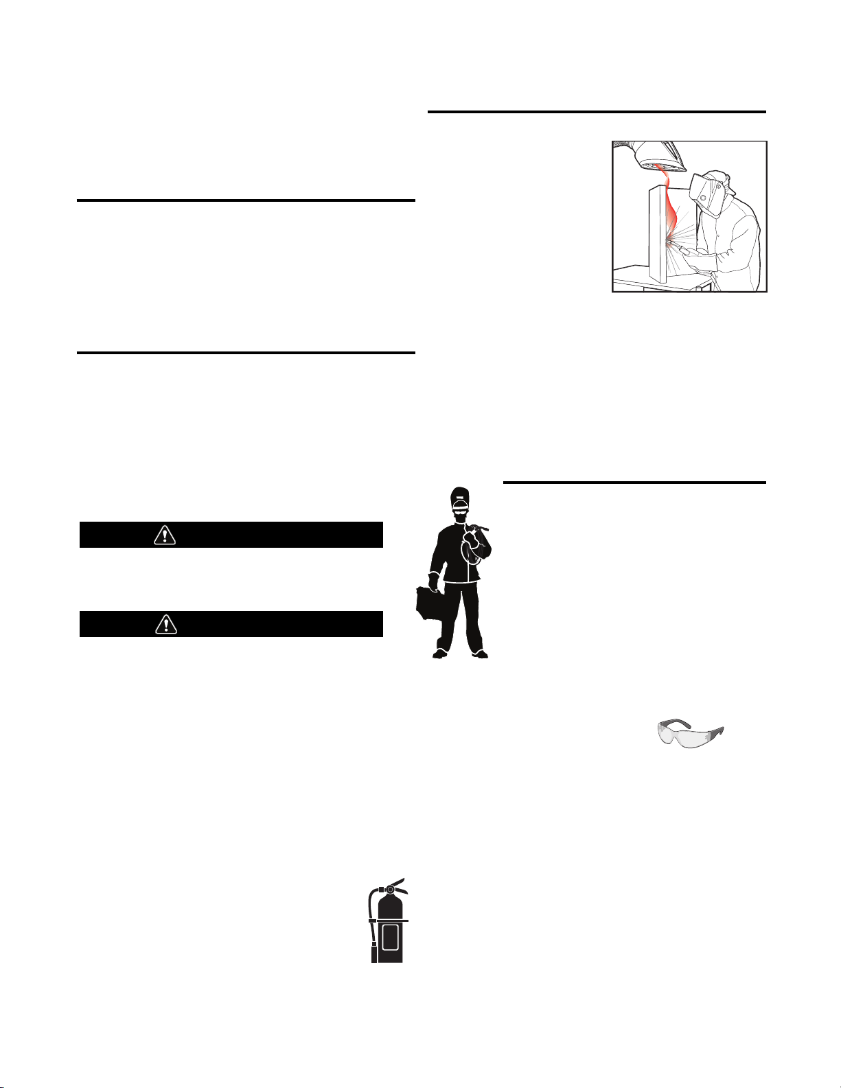
KEEP YOUR HEAD OUT OF THE FUMES.
DON’T get too close to the arc.
se corrective lenses if necessary
U
to stay a reasonable distance
away from the arc.
READ and obey the Safety Data
Sheet (SDS) and the warning label
that appears on all containers of
welding materials.
USE ENOUGH VENTILATION or
exhaust at the arc, or both, to
keep the fumes and gases from
your breathing zone and the general area.
IN A LARGE ROOM OR OUTDOORS, natural ventilation may be
adequate if you keep your head out of the fumes (See below).
USE NATURAL DRAFTS or fans to keep the fumes away
from your face.
If you de velop unusual symptoms, see your supervisor.
Perhaps the welding atmosphere and ventilation system
should be checked.
WEAR CORRECT EYE, EAR &
BODY PROTECTION
PROTECT your eyes and face with welding helmet
properly fitted and with proper grade of filter plate
(See ANSI Z49.1).
PROTECT your body from welding spatter and arc
flash with protective clothing including woolen
clothing, flame-proof apron and gloves, leather
leggings, and high boots.
PROTECT others from splatter, flash, and glare
with protective screens or barriers.
IN SOME AREAS, protection from noise may be appropriate.
BE SURE protective equipment is in good condition.
Also, wear safety glasses in work area
AT ALL TIMES.
SPECIAL SITUATIONS
DO NOT WELD OR CUT containers or materials which previously
had been in contact with hazardous substances unless they are
properly cleaned. This is extremely dangerous.
DO NOT WELD OR CUT painted or plated parts unless special
precautions with ventilation have been taken. They can release
highly toxic fumes or gases.
Additional precautionary measures
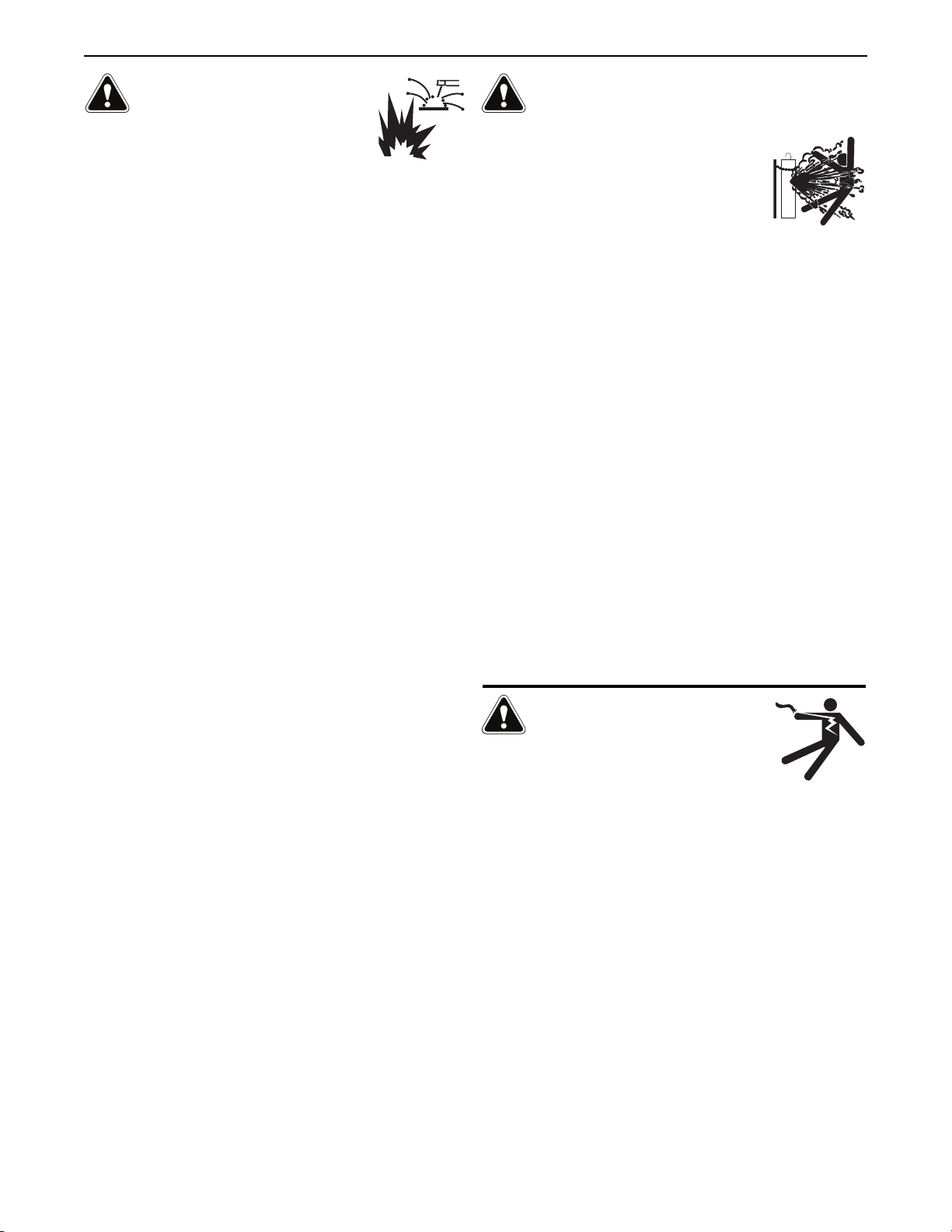
PROTECT compressed gas cylinders from excessive heat,
mechanical shocks, and arcs; fasten cylinders so they cannot fall.
BE SURE cylinders are never grounded or part of an
electrical circuit.
REMOVE all potential fire hazards from welding area.
ALWAYS HAVE FIRE FIGHTING EQUIPMENT READY FOR
IMMEDIATE USE AND KNOW HOW TO USE IT.
Safety 01 of 04 - 06/15/2016
Page 3
SECTION A:
WARNINGS
CALIFORNIA PROPOSITION 65 WARNINGS
Diesel Engines
Diesel engine exhaust and some of its constituents are known
to the State of California to cause cancer, birth defects, and other
reproductive harm.
Gasoline Engines
The engine exhaust from this product contains chemicals known
to the State of California to cause cancer, birth defects, or other
reproductive harm.
ARC WELDING CAN BE HAZARDOUS. PROTECT
YOURSELF AND OTHERS FROM POSSIBLE SERIOUS
INJURY OR DEATH. KEEP CHILDREN AWAY.
PACEMAKER WEARERS SHOULD CONSULT WITH
THEIR DOCTOR BEFORE OPERATING.
Read and understand the following safety highlights. For
additional safety information, it is strongly recommended
that you purchase a copy of “Safety in Welding & Cutting ANSI Standard Z49.1” from the American Welding Society,
P.O. Box 351040, Miami, Florida 33135 or CSA Standard
W117.2-1974. A Free copy of “Arc Welding Safety” booklet
E205 is available from the Lincoln Electric Company,
22801 St. Clair Avenue, Cleveland, Ohio 44117-1199.
BE SURE THAT ALL INSTALLATION, OPERATION,
MAINTENANCE AND REPAIR PROCEDURES ARE
PERFORMED ONLY BY QUALIFIED INDIVIDUALS.
SAFETY
1.d. Keep all equipment safety guards, covers
and devices in position and in good repair.
Keep hands, hair, clothing and tools away
from V-belts, gears, fans and all other
moving parts when starting, operating or
repairing equipment.
1.e. In some cases it may be necessary to remove safety guards to
perform required maintenance. Remove guards only when
necessary and replace them when the maintenance requiring
heir removal is complete. Always use the greatest care when
t
working near moving parts.
1.f. Do not put your hands near the engine fan. Do not attempt to
override the governor or idler by pushing on the throttle control
rods while the engine is running.
1.g. To prevent accidentally starting gasoline engines while turning
the engine or welding generator during maintenance work,
disconnect the spark plug wires, distributor cap or magneto wire
as appropriate.
1.h. To avoid scalding, do not remove the radiator
pressure cap when the engine is
hot.
ELECTRIC AND
MAGNETIC FIELDS MAY
BE DANGEROUS
2.a. Electric current flowing through any conductor
causes localized Electric and Magnetic Fields (EMF).
Welding current creates EMF fields around welding cables
and welding machines
FOR ENGINE POWERED
EQUIPMENT.
1.a. Turn the engine off before troubleshooting
and maintenance work unless the
maintenance work requires it to be running.
1.b. Operate engines in open, well-ventilated
areas or vent the engine exhaust fumes outdoors.
1.c. Do not add the fuel near an open flame
welding arc or when the engine is running.
Stop the engine and allow it to cool before
refueling to prevent spilled fuel from
vaporizing on contact with hot engine parts
and igniting. Do not spill fuel when filling
tank. If fuel is spilled, wipe it up and do not start engine until
fumes have been eliminated.
2.b. EMF fields may interfere with some pacemakers, and
welders having a pacemaker should consult their physician
before welding.
2.c. Exposure to EMF fields in welding may have other health effects
which are now not known.
2.d. All welders should use the following procedures in order to
minimize exposure to EMF fields from the welding circuit:
2.d.1. Route the electrode and work cables together - Secure
them with tape when possible.
2.d.2. Never coil the electrode lead around your body.
2.d.3. Do not place your body between the electrode and work
cables. If the electrode cable is on your right side, the
work cable should also be on your right side.
2.d.4. Connect the work cable to the workpiece as close as possible to the area being welded.
2.d.5. Do not work next to welding power source.
Safety 02 of 04 - 06/15/2016
Page 4
SAFETY
ELECTRIC SHOCK
CAN KILL.
3.a. The electrode and work (or ground) circuits are
electrically “hot” when the welder is on. Do
not touch these “hot” parts with your bare skin or wet clothing.
Wear dry, hole-free gloves to insulate hands.
3.b. Insulate yourself from work and ground using dry insulation.
Make certain the insulation is large enough to cover your full area
f physical contact with work and ground.
o
In addition to the normal safety precautions, if
welding must be performed under electrically
hazardous conditions (in damp locations or while
wearing wet clothing; on metal structures such as
floors, gratings or scaffolds; when in cramped
positions such as sitting, kneeling or lying, if there
is a high risk of unavoidable or accidental contact
with the workpiece or ground) use the following
equipment:
• Semiautomatic DC Constant Voltage (Wire) Welder.
• DC Manual (Stick) Welder.
• AC Welder with Reduced Voltage Control.
3.c. In semiautomatic or automatic wire welding, the electrode,
electrode reel, welding head, nozzle or semiautomatic welding
gun are also electrically “hot”.
3.d. Always be sure the work cable makes a good electrical
connection with the metal being welded. The connection should
be as close as possible to the area being welded.
3.e. Ground the work or metal to be welded to a good electrical (earth)
ground.
3.f. Maintain the electrode holder, work clamp, welding cable and
welding machine in good, safe operating condition. Replace
damaged insulation.
3.g. Never dip the electrode in water for cooling.
3.h. Never simultaneously touch electrically “hot” parts of electrode
holders connected to two welders because voltage
two can be the total of the open circuit voltage of both
welders.
3.i. When working above floor level, use a safety belt to protect
yourself from a fall should you get a shock.
between the
ARC RAYS CAN BURN.
4.a. Use a shield with the proper filter and cover plates to protect your
eyes from sparks and the rays of the arc when welding or
observing open arc welding. Headshield and filter lens should
conform to ANSI Z87. I standards.
4.b. Use suitable clothing made from durable flame-resistant material
to protect your skin and that of your helpers from the arc rays.
4.c. Protect other nearby personnel with suitable, non-flammable
screening and/or warn them not to watch the arc nor expose
themselves to the arc rays or to hot spatter or metal.
FUMES AND GASES
CAN BE DANGEROUS.
5.a. Welding may produce fumes and gases
hazardous to health. Avoid breathing these fumes and gases.
When welding, keep your head out of the fume. Use enough
ventilation and/or exhaust at the arc to keep fumes and gases
away from the breathing zone. When welding hardfacing
(see instructions on container or SDS) or on lead
or cadmium plated steel and other metals or
coatings which produce highly toxic fumes, keep
exposure as low as possible and within applicable
OSHA PEL and ACGIH TLV limits using local
exhaust or mechanical ventilation unless exposure
assessments indicate otherwise. In confined
spaces or in some circumstances, outdoors, a
respirator may also be required. Additional
precautions are also required when welding
on galvanized steel.
5. b. The operation of welding fume control equipment is affected by
various factors including proper use and positioning of the
equipment, maintenance of the equipment and the specific
welding procedure and application involved. Worker exposure
level should be checked upon installation and periodically
thereafter to be certain it is within applicable OSHA PEL and
ACGIH TLV limits.
5.c. Do not weld in locations near chlorinated hydrocarbon vapors
coming from degreasing, cleaning or spraying operations. The
heat and rays of the arc can react with solvent vapors to form
phosgene, a highly toxic gas, and other irritating products.
3.j. Also see It ems 6.c. and 8.
5.d. Shielding gases used for arc welding can displace air and
cause
injury or death. Always use enough ventilation, especially in
confined areas, to insure breathing air is safe.
5.e. Read and understand the manufacturer’s instructions for this
equipment and the consumables to be used, including the
Safety Data Sheet (SDS) and follow your employer’s safety
practices. SDS forms are available from your welding
distributor or from the manufacturer.
5.f. Also see item 1.b.
Safety 03 of 04 - 06/15/2016
Page 5
SAFETY
WELDING AND CUTTING
SPARKS CAN CAUSE
FIRE OR EXPLOSION.
6.a. Remove fire hazards from the welding area. If
this is not possible, cover them to prevent the welding sparks
rom starting a fire. Remember that welding sparks and hot
f
materials from welding can easily go through small cracks and
openings to adjacent areas. Avoid welding near hydraulic lines.
Have a fire extinguisher readily available.
6.b. Where compressed gases are to be used at the job site, special
precautions should be used to prevent hazardous situations.
Refer to “Safety in Welding and Cutting” (ANSI Standard Z49.1)
and the operating information for the equipment being used.
6.c. When not welding, make certain no part of the electrode circuit is
touching the work or ground. Accidental contact can cause
overheating and create a fire hazard.
6.d. Do not heat, cut or weld tanks, drums or containers until the
proper steps have been taken to insure that such procedures
will not cause flammable or toxic vapors from substances inside.
They can cause an explosion even though they have been
“cleaned”. For information, purchase “Recommended Safe
Practices for the Preparation for Welding and Cutting of
Containers and Piping That Have Held Hazardous Substances”,
AWS F4.1 from the American Welding Society
(see address above).
6.e. Vent hollow castings or containers before heating, cutting or
welding. They may explode.
6.f. Sparks and spatter are thrown from the welding arc. Wear oil free
protective garments such as leather gloves, heavy shirt, cuffless
trousers, high shoes and a cap over your hair. Wear ear plugs
when welding out of position or in confined places. Always wear
safety glasses with side shields when in a welding area.
6.g. Connect the work cable to the work as close to the welding area
as practical. Work cables connected to the building framework or
other locations away from the welding area increase the
possibility of the welding current passing through lifting chains,
crane cables or other alternate circuits. This can create fire
hazards or overheat lifting chains or cables until they fail.
6.h. Also see item 1.c.
CYLINDER MAY EXPLODE IF
DAMAGED.
7.a. Use only compressed gas cylinders containing
the correct shielding gas for the process used
and properly operating regulators designed for
the gas and pressure used. All hoses, fittings,
tc. should be suitable for the application and
e
maintained in good condition.
7.b. Always keep cylinders in an upright position securely chained to
an undercarriage or fixed support.
7.c. Cylinders should be located:
• Away from areas where they may be struck or subjected
to physical damage.
• A safe distance from arc welding or cutting operations
and any other source of heat, sparks, or flame.
7.d. Never allow the electrode, electrode holder or any other
electrically “hot” parts to touch a cylinder.
7.e. Keep your head and face away from the cylinder valve outlet
when opening the cylinder valve.
7.f. Valve protection caps should always be in place and hand tight
except when the cylinder is in use or connected for use.
7.g. Read and follow the instructions on compressed gas cylinders,
associated equipment, and CGA publication P-l, “Precautions for
Safe Handling of Compressed Gases in Cylinders,” available from
the Compressed Gas Association, 14501 George Carter Way
Chantilly, VA 20151.
FOR ELECTRICALLY
POWERED EQUIPMENT.
8.a. Turn off input power using the disconnect
switch at the fuse box before working on
the equipment.
8.b. Install equipment in accordance with the U.S. National Electrical
Code, all local codes and the manufacturer’s recommendations.
6.I. Read and follow NFPA 51B “Standard for Fire Prevention During
Welding, Cutting and Other Hot Work”, available from NFPA, 1
Batterymarch Park, PO box 9101, Quincy, MA 022690-9101.
6.j. Do not use a welding power source for pipe thawing.
8.c. Ground the equipment in accordance with the U.S. National
Electrical Code and the manufacturer’s recommendations.
Refer to
http://www.lincolnelectric.com/safety
for additional safety information.
Safety 04 of 04 - 06/15/2016
Page 6

NVERTER ARC 120
I
T
S
N
I
H
C
E
T
E
L
E
S
C
A
T
S
IN
T
IL
T
H
IG
H
U
P
IN
P
T
U
O
T
C
A
F
R
E
P
O
E
N
E
G
D
L
E
W
IT
IM
L
T
N
O
C
-
C
R
A
C
E
L
E
K
A
M
I
T
P
O
MAIN
ROUT
IN
A
C
T
O
W
T
O
N
K
F
U
A
R
IN
A
R
TE
INE
TABLE OF CONTENTS
A
N
O
I
T
C
E
S
.
.
.
.
.
.
.
.
.
.
.
.
.
.
.
.
.
.
.
.
.
.
.
.
.
.
.
.
.
.
.
.
.
.
.
.
.
.
.
.
.
.
.
.
.
.
.
.
.
.
.
.
.
.
.
.
.
.
.
.
.
.
.
.
.
.
.
.
.
.
.
.
.
.
.
.
.
.
.
.
.
.
.
.
.
.
.
.
.
.
.
.
.
.
.
.
.
.
.
.
.
.
.
.
.
.
.
.
.
.
.
.
.
.
.
.
.
.
.
.
.
.
.
.
.
.
.
.
.
.
.
.
.
.
.
.
.
.
.
.
.
N
O
I
T
A
L
L
1
-
A
.
.
.
.
.
.
.
.
.
.
.
.
.
.
.
.
.
.
.
.
.
.
.
.
.
.
.
.
.
.
.
.
.
.
.
.
.
.
.
.
.
.
.
.
.
.
.
.
.
.
.
.
.
.
.
.
.
.
.
.
.
.
.
.
.
.
.
.
.
.
.
.
.
.
.
.
.
.
.
.
.
.
.
.
.
.
.
.
.
.
.
.
.
.
.
.
.
.
.
.
.
.
.
.
.
.
.
.
.
.
.
.
.
.
.
.
.
.
.
.
.
.
.
.
.
.
.
.
.
.
.
.
S
N
IO
T
A
IC
IF
C
E
P
S
L
A
IC
1
-
A
.
.
.
.
.
.
.
.
.
.
.
.
.
.
.
.
.
.
.
.
.
.
.
.
.
.
.
.
.
.
.
.
.
.
.
.
.
.
.
.
.
.
.
.
.
.
.
.
.
.
.
.
.
.
.
.
.
.
.
.
.
.
.
.
.
.
.
.
.
.
.
.
.
.
.
.
.
.
.
.
.
.
.
.
.
.
.
.
.
.
.
.
.
.
.
.
.
.
.
.
.
.
.
.
.
.
.
.
.
.
.
.
.
.
.
.
.
.
.
.
.
.
.
.
.
.
.
.
.
.
.
.
.
N
IO
T
A
C
O
L
E
L
B
A
IT
U
S
T
1
-
A
.
.
.
.
.
.
.
.
.
.
.
.
.
.
.
.
.
.
.
.
.
.
.
.
.
.
.
.
.
.
.
.
.
.
.
.
.
.
.
.
.
.
.
.
.
.
.
.
.
.
.
.
.
.
.
.
.
.
.
.
.
.
.
.
.
.
.
.
.
.
.
.
.
.
.
.
.
.
.
.
.
.
.
.
.
.
.
.
.
.
.
.
.
.
.
.
.
.
.
.
.
.
.
.
.
.
.
.
.
.
.
.
.
.
.
.
.
.
.
.
.
.
.
.
.
.
.
.
.
.
.
.
.
.
.
.
.
.
.
.
.
.
.
.
.
.
.
.
.
.
.
.
.
.
.
.
G
IN
1
-
A
.
.
.
.
.
.
.
.
.
.
.
.
.
.
.
.
.
.
.
.
.
.
.
.
.
.
.
.
.
.
.
.
.
.
.
.
.
.
.
.
.
.
.
.
.
.
.
.
.
.
.
.
.
.
.
.
.
.
.
.
.
.
.
.
.
.
.
.
.
.
.
.
.
.
.
.
.
.
.
.
.
.
.
.
.
.
.
.
.
.
.
.
.
.
.
.
.
.
.
.
.
.
.
.
.
.
.
.
.
.
.
.
.
.
.
.
.
.
.
.
.
.
.
.
.
.
.
.
.
.
.
.
.
.
.
.
.
.
.
.
.
.
.
.
.
.
.
.
.
.
.
.
.
.
.
.
G
1
-
A
.
.
.
.
.
.
.
.
.
.
.
.
.
.
.
.
.
.
.
.
.
.
.
.
.
.
.
.
.
.
.
.
.
.
.
.
.
.
.
.
.
.
.
.
.
.
.
.
.
.
.
.
.
.
.
.
.
.
.
.
.
.
.
.
.
.
.
.
.
.
.
.
.
.
.
.
.
.
.
.
.
.
.
.
.
.
.
.
.
.
.
.
.
.
.
.
.
.
.
.
.
.
.
.
.
.
.
.
.
.
.
.
.
.
.
.
.
.
.
.
.
.
.
.
.
.
.
.
.
N
IO
T
C
E
T
O
R
P
Y
C
N
E
U
Q
E
R
2
-
. A
.
.
.
.
.
.
.
.
.
.
.
.
.
.
.
.
.
.
.
.
.
.
.
.
.
.
.
.
.
.
.
.
.
.
.
.
.
.
.
.
.
.
.
.
.
.
.
.
.
.
.
.
.
.
.
.
.
.
.
.
.
.
.
.
.
.
.
.
.
.
.
.
.
.
.
.
.
.
.
.
.
.
.
.
.
.
.
.
.
.
.
.
.
.
.
.
.
.
.
.
.
.
.
.
.
.
.
.
.
.
.
.
.
.
.
.
.
.
.
.
.
.
.
.
.
.
.
.
.
.
.
.
.
.
.
.
.
.
.
.
.
.
.
S
N
IO
T
C
E
N
N
O
C
2
-
A
.
.
.
.
.
.
.
.
.
.
.
.
.
.
.
.
.
.
.
.
.
.
.
.
.
.
.
.
.
.
.
.
.
.
.
.
.
.
.
.
.
.
.
.
.
.
.
.
.
.
.
.
.
.
.
.
.
.
.
.
.
.
.
.
.
.
.
.
.
.
.
.
.
.
.
.
.
.
.
.
.
.
.
.
.
.
.
.
.
.
.
.
.
.
.
.
.
.
.
.
.
.
.
.
.
.
.
.
.
.
.
.
.
.
.
.
.
.
.
.
.
.
.
.
.
.
.
.
.
.
.
.
.
.
.
.
.
.
.
.
.
S
N
IO
T
C
E
N
N
O
C
T
2
-
A
.
.
.
.
.
.
.
.
.
.
.
.
.
.
.
.
.
.
.
.
.
.
.
.
.
.
.
.
.
.
.
.
.
.
.
.
.
.
.
.
.
.
.
.
.
.
.
.
.
.
.
.
.
.
.
.
.
.
.
.
.
.
.
.
.
.
.
.
.
.
.
.
.
.
.
.
.
.
.
.
.
.
.
.
.
.
.
.
.
.
.
.
.
.
.
.
.
.
.
.
.
.
.
.
.
.
.
.
.
.
.
.
.
.
.
.
.
.
.
.
.
.
.
.
.
.
.
.
.
.
.
.
.
.
.
.
.
.
.
.
.
.
.
.
D
E
L
L
A
T
S
IN
Y
R
B
N
O
I
T
C
E
S
.
.
.
.
.
.
.
.
.
.
.
.
.
.
.
.
.
.
.
.
.
.
.
.
.
.
.
.
.
.
.
.
.
.
.
.
.
.
.
.
.
.
.
.
.
.
.
.
.
.
.
.
.
.
.
.
.
.
.
.
.
.
.
.
.
.
.
.
.
.
.
.
.
.
.
.
.
.
.
.
.
.
.
.
.
.
.
.
.
.
.
.
.
.
.
.
.
.
.
.
.
.
.
.
.
.
.
.
.
.
.
.
.
.
.
.
.
.
.
.
.
.
.
.
.
.
.
.
.
.
.
.
.
.
.
.
.
.
.
.
.
.
.
.
N
O
I
T
1
-
B
.
.
.
.
.
.
.
.
.
.
.
.
.
.
.
.
.
.
.
.
.
.
.
.
.
.
.
.
.
.
.
.
.
.
.
.
.
.
.
.
.
.
.
.
.
.
.
.
.
.
.
.
.
.
.
.
.
.
.
.
.
.
.
.
.
.
.
.
.
.
.
.
.
.
.
.
.
.
.
.
.
.
.
.
.
.
.
.
.
.
.
.
.
.
.
.
.
.
.
.
.
.
.
.
.
.
.
.
.
.
.
.
.
.
.
.
.
.
.
.
.
.
.
.
.
.
.
.
.
.
.
.
.
.
.
.
.
.
.
.
.
N
IO
T
IP
R
C
S
E
D
L
A
1
-
.B
.
.
.
.
.
.
.
.
.
.
.
.
.
.
.
.
.
.
.
.
.
.
.
.
.
.
.
.
.
.
.
.
.
.
.
.
.
.
.
.
.
.
.
.
.
.
.
.
.
.
.
.
.
.
.
.
.
.
.
.
.
.
.
.
.
.
.
.
.
.
.
.
.
.
.
.
.
.
.
.
.
.
.
.
.
.
.
.
.
.
.
.
.
.
.
.
.
.
.
.
.
.
.
.
.
.
.
.
.
.
.
.
.
.
.
.
.
.
.
.
.
.
.
.
.
.
.
.
.
.
.
.
.
.
.
.
.
.
.
.
.
.
.
Y
IT
IL
B
A
P
A
C
G
1
-
B
.
.
.
.
.
.
.
.
.
.
.
.
.
.
.
.
.
.
.
.
.
.
.
.
.
.
.
.
.
.
.
.
.
.
.
.
.
.
.
.
.
.
.
.
.
.
.
.
.
.
.
.
.
.
.
.
.
.
.
.
.
.
.
.
.
.
.
.
.
.
.
.
.
.
.
.
.
.
.
.
.
.
.
.
.
.
.
.
.
.
.
.
.
.
.
.
.
.
.
.
.
.
.
.
.
.
.
.
.
.
.
.
.
.
.
.
.
.
.
.
.
.
.
.
.
.
.
.
.
.
.
.
.
.
.
.
.
.
.
.
.
.
.
.
.
.
.
.
.
.
.
.
.
.
.
.
S
N
IO
T
2
-
B
.
.
.
.
.
.
.
.
.
.
.
.
.
.
.
.
.
.
.
.
.
.
.
.
.
.
.
.
.
.
.
.
.
.
.
.
.
.
.
.
.
.
.
.
.
.
.
.
.
.
.
.
.
.
.
.
.
.
.
.
.
.
.
.
.
.
.
.
.
.
.
.
.
.
.
.
.
.
.
.
.
.
.
.
.
.
.
.
.
.
.
.
.
.
.
.
.
.
.
.
.
.
.
.
.
.
.
.
.
.
.
.
S
E
R
U
T
A
E
F
L
A
N
IO
T
A
R
E
P
O
D
N
A
S
L
O
3
-
B
.
.
.
.
.
.
.
.
.
.
.
.
.
.
.
.
.
.
.
.
.
.
.
.
.
.
.
.
.
.
.
.
.
.
.
.
.
.
.
.
.
.
.
.
.
.
.
.
.
.
.
.
.
.
.
.
.
.
.
.
.
.
.
.
.
.
.
.
.
.
.
.
.
.
.
.
.
.
.
.
.
.
.
.
.
.
.
.
.
.
.
.
.
.
.
.
.
.
.
.
.
.
.
.
.
.
.
.
.
.
.
.
.
.
.
.
.
.
.
.
.
.
.
.
.
.
.
.
.
.
.
.
.
.
.
.
.
.
.
.
.
.
IT
U
C
IR
C
G
IN
D
L
E
3
-
B
.
.
.
.
.
.
.
.
.
.
.
.
.
.
.
.
.
.
.
.
.
.
.
.
.
.
.
.
.
.
.
.
.
.
.
.
.
.
.
.
.
.
.
.
.
.
.
.
.
.
.
.
.
.
.
.
.
.
.
.
.
.
.
.
.
.
.
.
.
.
.
.
.
.
.
.
.
.
.
.
.
.
.
.
.
.
.
.
.
.
.
.
.
.
.
.
.
.
.
.
.
.
.
.
.
.
.
.
.
.
.
.
.
.
.
.
.
.
.
.
.
.
.
.
.
.
.
.
.
.
.
.
.
.
.
.
.
.
.
.
.
.
.
.
.
.
.
.
.
.
.
.
.
.
.
C
R
A
IC
R
4
-
B
.
.
.
.
.
.
.
.
.
.
.
.
.
.
.
.
.
.
.
.
.
.
.
.
.
.
.
.
.
.
.
.
.
.
.
.
.
.
.
.
.
.
.
.
.
.
.
.
.
.
.
.
.
.
.
.
.
.
.
.
.
.
.
.
.
.
.
.
.
.
.
.
.
.
.
.
.
.
.
.
.
.
.
.
.
.
.
.
.
.
.
.
.
.
.
.
.
.
.
.
.
.
.
.
.
.
.
.
.
.
.
.
.
.
.
.
.
.
.
.
.
.
.
.
.
.
.
.
.
.
.
.
.
.
.
.
.
.
.
.
.
.
.
.
.
.
.
.
.
.
.
.
D
L
E
W
A
G
C
N
O
I
T
C
E
S
.
.
.
.
.
.
.
.
.
.
.
.
.
.
.
.
.
.
.
.
.
.
.
.
.
.
.
.
.
.
.
.
.
.
.
.
.
.
.
.
.
.
.
.
.
.
.
.
.
.
.
.
.
.
.
.
.
.
.
.
.
.
.
.
.
.
.
.
.
.
.
.
.
.
.
.
.
.
.
.
.
.
.
.
.
.
.
.
.
.
.
.
.
.
.
.
.
.
.
.
.
.
.
.
.
.
.
.
S
E
I
R
O
S
S
E
C
C
A
D
N
A
S
T
I
K
L
A
N
D
CTION
SE
.
.
.
.
.
.
.
.
.
.
.
.
.
.
.
.
.
.
.
.
.
.
.
.
.
.
.
.
.
.
.
.
.
.
.
.
.
.
.
.
.
.
.
.
.
.
.
.
.
.
.
.
.
.
.
.
.
.
.
.
.
.
.
.
.
.
.
.
.
.
.
.
.
.
.
.
.
.
.
.
.
.
.
.
.
.
.
.
.
.
.
.
.
.
.
.
.
.
.
.
.
.
.
.
.
.
.
.
.
.
.
.
.
.
.
.
.
.
.
.
.
.
.
.
.
.
.
.
.
.
.
.
.
.
.
.
.
.
.
.
.
CE
AN
N
1
.D-
.
.
.
.
.
.
.
.
.
.
.
.
.
.
.
.
.
.
.
.
.
.
.
.
.
.
.
.
.
.
.
.
.
.
.
.
.
.
.
.
.
.
.
.
.
.
.
.
.
.
.
.
.
.
.
.
.
.
.
.
.
.
.
.
.
.
.
.
.
.
.
.
.
.
.
.
.
.
.
.
.
.
.
.
.
.
.
.
.
.
.
.
.
.
.
.
.
.
.
.
.
.
.
.
.
.
.
.
.
.
.
.
.
.
.
.
.
.
.
.
.
.
.
.
.
.
.
.
.
.
.
.
.
.
.
.
.
.
.
NANCE
E
AINT
M
TROUBL
T
HOW
WIRIN
PARTS
E
CONT
O
T
GO
SHOOTIN
E
USE
O
IAGRAM
D
G
IST
L
/
NT
ART
P
DE
T
.
.
T
L
S.
ROUBL
.
.
.
.
.
.
.
S
AIL
INCOL
G
.
.
.
M
.
.
E
.
.
.
.
.
.
AY
NE
.
.
.
.
.
.
SHOOT
.
.
.
.
.
.
.
.
.
.
.
.
BE
E
L
.
.
.
.
.
.
.
.
.
.
.
.
.
.
.
.
.
.
CHANGE
RIC.
CT
.
.
.
ING
.
.
.
.
.
.
.
.
.
.
.
.
.
.
.
.
.
.
GUIDE
.
.
.
.
.
.
.
.
.
COM
E
CTION
SE
.
.
.
.
.
.
.
.
.
.
.
.
.
.
.
.
.
.
.
.
.
.
.
.
.
.
.
.
.
.
.
.
.
.
.
.
.
.
.
.
.
.
.
.
.
.
.
.
.
.
.
.
.
.
.
.
.
.
.
.
.
.
.
.
.
.
.
.
.
.
.
.
.
.
.
.
.
.
.
.
.
.
.
.
.
.
.
.
.
.
.
.
.
.
.
.
.
.
.
.
.
.
.
.
.
.
.
.
.
.
1
-
E
.
.
.
.
.
.
.
.
.
.
.
.
.
.
.
.
.
.
.
.
.
.
.
.
.
.
.
.
.
.
.
.
.
.
.
.
.
.
.
.
.
.
.
.
.
.
.
.
.
.
.
.
.
.
.
.
.
.
.
.
.
.
.
.
.
.
.
.
.
.
.
.
.
.
.
.
.
.
.
.
.
.
.
.
.
.
.
.
.
.
.
.
.
.
.
.
.
.
.
.
.
.
.
.
.
.
.
.
.
.
.
.
.
.
.
F
CTION
SE
.
.
.
.
.
.
.
.
.
.
.
.
.
.
.
.
.
.
.
.
.
.
.
.
.
.
.
.
.
.
.
.
.
.
.
.
.
.
.
.
.
.
.
.
.
.
.
.
.
.
.
.
.
.
.
.
.
.
.
.
.
.
.
.
.
.
.
.
.
.
.
.
.
.
.
.
.
.
.
.
.
.
.
.
.
.
.
.
.
.
.
.
.
.
.
.
.
.
.
.
.
.
.
.
.
.
.
.
.
.
COM
CTRIC.
E
L
E
N
COL
IN
L
PARTS.
.
.
.
.
.
.
.
.
.
.
.
.
.
.
.
.
.
.
.
.
.
.
.
.
.
.
.
.
.
.
.
.
.
.
.
.
.
.
.
.
.
.
.
.
.
.
.
.
.
.
.
.
.
.
.
.
.
.
.
.
.
.
.
.
.
.
.
.
.
.
.
.
.
.
.
.
S,
ANUAL
M
ION
RUCT
INST
NT
CURRE
OST
M
OR
F
.
ICE
NOT
HOUT
WIT
D
E
UPDAT
OR
D
.
2
Page 7

NVERTER ARC 120
I
NSTALLATION
I
INSTALLATION
TECHNICAL SPECIFICATIONS -
K2789-2 - Inverter Arc 120
INPUT - SINGLE PHASE ONLY
Input Voltages 60 Hz. Rated Input Current
120VAC ± 15% 20 AMPS @ RATED OUTPUT
RATED OUTPUT
Duty Cycle Output Amps Output Volts Input Circuit
20% 70A (STICK) 22.8 VDC 120 VAC
OUTPUT
Output Current Range
10-90 AMPS 75 VOLTS MAX. DC
RECOMMENDED INPUT WIRE AND FUSE SIZES FOR
MAXIMUM RATED OUTPUT
INPUT VOLTAGE /
FREQUENCY (HZ)
120/60
PHYSICAL DIMENSIONS
Height
Width
Depth
Weight
TEMPERATURE RANGES
Operating
Temperature
Storage
Temperature
Maximum Open
Circuit Voltage
TYPE SJT OR
HARD USAGE
INPUT CORD
MAXIMUM TIME-DELAY
CIRCUIT BREAKER OR FUSE
3 CONDUCTOR,
14 AWG
9.0 IN. (228.6 MM)
4.5 IN. (114.3 MM)
13.7 IN. (348.0 MM)
APPROX. 14.0 LBS. (6.4 KGS.)
-10°C TO +40°C
-25°C TO +55°C
Type of Output
SIZE (AMPS)
20
SAFETY PRECAUTIONS
WARNING
ELECTRIC SHOCK can kill.
• Only qualified personnel should
erform this installation.
p
• Disconnect input power by removing
plug from receptacle before working
inside Inverter Arc 120 Allow machine
to sit for 5 minutes minimum to allow
the power capacitors to discharge before working
inside this equipment.
• Insulate yourself from the work and ground.
• Always wear dry insulating gloves.
• Always connect the Inverter Arc 120 to a power supply
grounded according to the National Electrical Code and
local codes.
SELECT SUITABLE LOCATION
This machine can operate in harsh environments.
However, it is important that simple preventative measures are
followed to assure long life and reliable operation:
• This machine must be located where there is free circulation
of clean air without restrictions for air movement to and from
the air vents. Do not cover the machine with paper, cloth or
rags when switched on.
• Dirt and dust that can be drawn into the machine should be
kept to a minimum.
• This machine has a protection rating of IP21S. Keep it dry
and do not place it on wet ground or in puddles. Do not use in
wet or damp locations. Store indoors.
• Locate the machine away from radio controlled machinery.
Normal operation may adversely affect the operation of
nearby radio controlled machinery, which may result in injury
or equipment damage. Read the section on electromagnetic
compatibility in this manual.
• Do not operate in areas with an ambient temperature greater
than 40°C.
STACKING
The Inverter Arc 120 cannot be stacked.
Thermal tests have been performed at ambient temperature. The duty
cycle (duty factor) at 40°C has been determined by simulation.
TILTING
Place the machine directly on a secure, level surface. Do not place
or operate this machine on a surface with an incline greater than
15° from horizontal. The machine may topple over if this
procedure is not followed.
HIGH FREQUENCY PROTECTION
Locate the Inverter Arc 120 away from radio controlled machinery.
The normal operation of the Inverter Arc 120 may adversely affect
the operation of RF controlled equipment, which may result in
bodily injury or damage to the equipment.
A-1
Page 8

NVERTER ARC 120
Electrode Holder
Work Cable
Positive “+”
Negative “–”
Work Clamp
I
NPUT CONNECTIONS
I
Ground Connection
The frame of the welder must be grounded. A
ground terminal marked with the symbol is located
on the under panel for this purpose. See your local
and national electrical codes for proper grounding
ethods.
m
TABLE A.1
BRANCH CIRCUITS
120V Input Output Current
LUG RATING
P
BRANCH
RATING
20% DUTY
CYCLE
15 AMP 15 AMP 55A 60A
15 AMP 20 AMP 70A 80A
NSTALLATION
I
10% DUTY
CYCLE
WARNING
A grounding conductor is supplied
in the input cord, it is important
that the supply receptacle ground
is connected.
• The welding power source supply cable
is provided with a green or
yellow/green wire that must ALWAYS be earthed. This
green or yellow/green wire must NEVER be used with
other voltage conductors.
• Only install plugs that conform with safety regulations.
Input Power Connection
Check the input voltage, phase, and frequency supplied to this
machine before turning it on. The allowable input voltage is
indicated in the technical specification section of this manual and
on the rating plate of the machine. Be sure that the machine is
grounded.
Make sure the power available at the input connection is adequate
for normal operation of the machine. The fuse rating and cable
sizes are both indicated in the technical specification section of
this manual.
Fuse the input circuit with time delay fuses marked “D” or delay
(1)
type
circuit breakers. Using fuses or circuit breakers smaller
than recommended may result in “nuisance” shut-offs from
welder inrush currents even if not welding at high currents.
(1) Also called “inverse time” or “thermal/magnetic” circuit breakers. These
circuit breakers have a delay in tripping action that decreases as the magnitude of the current increases.
The Inverter Arc 120 is recommended for use on an individual
branch circuit.
OUTPUT CONNECTIONS
A quick disconnect system using Twist-Mate™ cable plugs is
used for the welding cable connections.
WARNING
ELECTRIC SHOCK can kill.
• Keep the electrode holder and cable
insulation in good condition.
• Do not touch electrically live parts or
electrode with skin or wet clothing.
• Insulate yourself from work and ground.
• Turn the input line Switch on the AUTOPRO™ 90S “off”
before connecting or disconnecting output cables or
other equipment.
Stick Welding (SMAW)
Connect the electrode cable to the (+) terminal and the work
clamp to the (-) terminal. Insert the connector with the key lining
up with the keyway and rotate approximately 1/4 turn clockwise.
Do not over tighten.
(See Figure A.1)
FIGURE A.1
120v INPUT
The INVERTER ARC™ 120 is provided with a 120V cable,
6.0ft.(1.8m) in length, with a 15Amp 5-15P plug molded onto the
cord.
The rated output of the INVERTER ARC™ 120 is available when
connected to a 20A branch circuit. When connected to a branch
circuit with lower ampacity, lower welding current and duty cycle
must be used. An output guide is provided below. The values are
approximate and must be adjusted downward if the fuse or circuit
breaker trips off. Other loads on the circuit and fuse/circuit
breaker characteristics will affect the available output. Do not
exceed these welding conditions: (See Table A.1)
A-2
Page 9

INVERTER ARC 120
PERATION
O
OPERATION
Read and understand this entire section before operating
your machine.
Safety Precautions
Do not attempt to use this equipment until you have
thoroughly read all operating and maintenance manuals
supplied with your equipment and any related welding
achine it will be used with. They include important safety
m
precautions, operating and maintenance instructions and
parts lists.
WARNING
ELECTRIC SHOCK can kill.
• Do not touch electrically live parts such as
output terminals or internal wiring.
• Insulate yourself from the work and
ground.
• Always wear dry insulating gloves.
WELDING SPARKS can cause fire
or explosion.
• Keep flammable material away.
• Do not weld upon containers which have
held combustibles.
GENERAL DESCRIPTION
The INVERTER ARC™ 120 is a 90 amp arc welding power source
hich utilizes single phase input power to produce constant
w
current output. The welding response of this Inverter has been
optimized for stick (SMAW) welding.
WELDING CAPABILITY
The INVERTER ARC™ 120 is rated at 70 amps, 22.8 volts, at 20%
duty cycle on a ten minute basis. It is capable of higher duty
cycles at lower output currents. If the duty cycle is exceeded, a
thermal protector will shut off the output until the machine cools.
See Table A.1 in the Installation Section for other rated outputs.
The INVERTER ARC™ 120 is recommended for the following
Electrode Types and Diameters:
TABLE A.2
SIZES (IN.)
Types 1/16 5/64 3/32 1/8
FLEETWELD 37
(E6013)
FLEETWELD 35
(E6011)
EXCALIBUR 7018 MR
(E7018)
Amp Branch circuit or greater required.
∆ - 20 Amp Branch circuit or greater required.
X X
- - X
- -
-
∆
∆
-
∆
LIMITATIONS
The Inverter Arc 120 is not recommended for pipe thawing.
ARC RAYS can burn.
• Wear eye, ear and body protection.
FUMES AND GASES can
be dangerous.
Although the removal of the particulate
matter from welding smoke may reduce
the ventilation requirement, concentrations
of the clear exhausted fumes and gases
may still be hazardous to health. Avoid breathing concentrations of these fumes and gases. Use adequate
ventilation when welding. See ANSI Z49.1, "Safety in
Welding and Cutting", published by the American Welding
Society.
Only qualified personnel should operate this equipment.
Observe all safety information throughout this manual.
B-1
Page 10

INVERTER ARC 120
1
2
3
4
5
6
7
ONTROLS AND OPERATIONAL FEATURES
C
FRONT CONTROL PANEL
REAR CONTROL PANEL
PERATION
O
1. Output Current Knob: Potentiometer used to set the output
current used during welding. Set the output according to the
type and size of electrode.
2. Power LED: After the Power Switch is turned on the LED will
illuminate.
3. Thermal LED: This indicator will turn on when the machine is
overheated and the output has been disabled. This normally
occurs when the duty cycle of the machine has been
exceeded. Leave the machine on to allow the internal
components to cool. When the indicator turns off, normal
operation is again possible.
4. Positive Quick Disconnect: Positive output connector for the
welding circuit.
5. Negative Quick Disconnect: Negative output connector for
the welding circuit.
FIGURE B.1
(See Figure B.2)
6. Power Switch: It turns ON / OFF the input power to the
machine.
7. Input cable: This machine is provided with a plugged input
cord. Connect it to the mains.
FIGURE B.2
B-2
Page 11

W
ork Cable
Electrode Cable
W
ork Clamp
E
lectrode
Arc
E
lectrode Holder
Work Piece
INVERTER ARC 120
PERATION
O
RC-WELDING CIRCUIT
A
(See Figure B.3)
IGURE B.3
F
Current flows through the electrode cable and electrode holder to
the electrode and across the arc. On the work side of the arc, the
current flows through the base metal to the work cable and back
to the welding machine. The circuit must be complete for the
current to flow.
To weld, the work clamp must be tightly connected to clean base
metal. Remove paint, rust, etc. as necessary to get a good
connection. Connect the work clamp as close as possible to the
area you wish to weld. Avoid allowing the welding circuit to pass
through hinges, bearings, electronic components or similar
devices that can be damaged.
An electric arc is made between the work and the end of a small
metal rod, the electrode, which is clamped in a holder and the
holder is held by the person doing the welding. A gap is made in
the welding circuit (see Figure B.3) by holding the tip of the
electrode 1/16-1/8” away from the work or base metal being
welded. The electric arc is established in this gap and is held and
moved along the joint to be welded, melting the metal as it is
moved.
LECTRIC ARC
E
(See Figure B.4)
Action that takes place in the electric arc.
IGURE B.4
F
This figure closely resembles what is actually seen during
welding. The “arc stream’’ is seen in the middle of the figure. This
is the electric arc created by the electric current flowing through
the space between the end of the electrode and the work.
The temperature of this arc is about 6000°F (3315°C), which is
more than enough to melt metal. The arc is very bright, as well as
hot, and cannot be looked at with the naked eye without risking
painful injury. A very dark lens, specifically designed for arc
welding, must be used with a hand or face shield whenever
viewing the arc. The arc melts the base metal and actually digs
into it, much as water through a nozzle on a garden hose digs into
the earth. The molten metal forms a pool or crater and tends to
flow away from the arc. As it moves away from the arc, it cools
and solidifies. A slag forms on top of the weld to protect it during
cooling.
The function of the covered electrode is much more than simply to
carry current to the arc. The electrode is composed of a core rod
of metal with an extruded chemical covering. The core rod melts
in the arc and tiny droplets of molten metal shoot across the arc
into the molten pool. The electrode provides additional filler metal
for the joint to fill the groove or gap between the two pieces of the
base metal. The covering also melts or burns in the arc. It has
several functions. It makes the arc steadier, provides a shield of
smoke-like gas around the arc to keep oxygen and nitrogen in the
air away from the molten metal, and provides a flux for the molten
pool. The flux picks up impurities and forms the protective slag.
B-3
Page 12

INVERTER ARC 120
PERATION
O
AKING A WELD
M
Insert the bare part of the electrode into the electrode holder jaws
and connect the work clamp to the welding piece. Make sure to
have good electrical contact.
1. Turn the welder on.
2. Lower your welding helmet to protect your face and eyes.
3. Strike the electrode at the work point on the workpiece as if
striking a match. Do not hit the electrode on the workpiece,
which will damage the stick electrode and make striking an
arc difficult. Scratch the electrode slowly over the metal and
you will see sparks. While scratching, lift the electrode 1/8"
(3.2mm) and the arc will establish.
NOTE: If you stop moving the electrode while scratching, the
electrode will stick.
NOTE: Most beginners try to strike the arc by a fast jabbing motion
down on the plate. Result: They either stick or their motion
is so fast that they break the arc immediately.
4. Immediately after striking the arc try to maintain a distance
from the workpiece that is equivalent to the diameter of the
electrode used. Maintain this distance as constantly as
possible during the weld. Whenever possible, weld from left
to right (if right-handed). Hold the electrode at a slight angle
as shown. (See Figure B.5)
FIGURE B.5
. The important thing to watch while welding is the puddle of
6
molten metal right behind the arc. Do NOT watch the arc
itself. It is the appearance of the puddle and the ridge where
the molten puddle solidifies that indicate correct welding
peed. The ridge should be approximately 3/8" (9.5mm)
s
behind the electrode. (See Figure B.6)
IGURE B.6
F
Most beginners tend to weld too fast, resulting in a thin, uneven,
“wormy” looking bead. They are not watching the molten metal.
IMPORTANT: For general welding it is not necessary to weave the
arc; neither forwards and backwards nor sideways. Weld
along at a steady pace. You will find it easier. NOTE: When
welding on thin plate, you will find that you will have to
increase the welding speed, whereas when welding on heavy
plate, it is necessary to go more slowly in order to get good
penetration.
7. Once the electrode is burned down move the electrode
quickly from the weld to extinguish the arc.
8. Turn the machine off and remove the stub by opening the
jaws of the electrode holder and insert a new electrode.
Note: The welded work piece and electrode stub are hot after
welding. Allow them to cool down before touching or use
pliers to move. Always make sure the welder is turned off
before setting down the Electrode Holder.
5. As the electrode burns off the electrode must be fed to the
work to maintain correct arc length. The easiest way to tell
whether the arc has the correct length is by listening to its
sound. A nice, short arc has a distinctive, “crackling” sound,
very much like eggs frying in a pan. The incorrect, long arc
has a hollow, blowing or hissing sound.
B-4
Page 13

INVERTER ARC 120
OPTIONAL KITS AND
ACCESSORIES
CCESSORIES
A
C-1
Page 14

INVERTER ARC 120
AINTENANCE
M
MAINTENANCE
WARNING
ELECTRIC SHOCK can kill.
• Turn the input power OFF at the welding
power source before installation or
changing drive rolls and/or guides.
• Do not touch electrically live parts.
• When inching with the gun trigger, electrode and drive
mechanism are "hot" to work and ground and could
remain energized several seconds after the gun trigger
is released.
• Do not operate with covers, panels or guards removed
or open.
• Only qualified personnel should perform maintenance
work.
ROUTINE MAINTENANCE
The frequency of the maintenance operations may vary in
accordance with the working environment. Any noticeable
damage should be reported immediately.
• Check cables and connections integrity. Replace, if
necessary.
• Clean the power source inside by means of low - pressure
compressed air.
• Keep the machine clean. Use a soft dry cloth to clean the
external case, especially the airflow inlet / outlet louvers.
WARNING
TROUBLESHOOTING
HOW TO USE TROUBLESHOOTING GUIDE
WARNING
Service and Repair should only be performed by Lincoln
Electric Factory Trained Personnel. Unauthorized repairs
performed on this equipment may result in danger to the
technician and machine operator and will invalidate your
factory warranty. For your safety and to avoid Electrical
Shock, please observe all safety notes and precautions
etailed throughout this manual.
d
This Troubleshooting Guide is provided to help you locate and
repair possible machine malfunctions. Simply follow the threestep procedure listed below.
Step 1. LOCATE PROBLEM (SYMPTOM).
Look under the column labeled “PROBLEM (SYMPTOMS).” This
column describes possible symptoms that the machine may
exhibit. Find the listing that best describes the symptom that the
machine is exhibiting.
Step 2. POSSIBLE CAUSE.
The second column labeled “POSSIBLE CAUSE” lists the obvious
external possibilities that may contribute to the machine symptom.
Step 3. RECOMMENDED COURSE OF ACTION
This column provides a course of action for the Possible Cause,
generally it states to contact you local Lincoln Authorized Field
Service Facility.
If you do not understand or are unable to perform the
Recommended Course of Action safely, contact your local
Lincoln Authorized Field Service Facility.
Do not open this machine and do not introduce anything into its openings. Power supply
must be disconnected from the machine
before each maintenance and service. After
each repair, perform proper tests to ensure
safety.
WARNING
Power supply must be disconnected from the
machine before each maintenance and service. Always use gloves in compliance with
the safety standards.
E
WARNING
ELECTRIC SHOCK can kill.
• Turn off machine at the disconnect switch
on the rear of the machine and remove
main power supply connections before
doing any troubleshooting.
D-1
Page 15

NVERTER ARC 120
I
TROUBLESHOOTING
Observe all Safety Guidelines detailed throughout this manual
PROBLEM
(SYMPTOMS)
POSSIBLE AREAS OF
MISADJUSTMENT(S)
ELDING PROBLEMS
W
RECOMMENDED COURSE OF ACTION
Excessive spatter 1. Improper welding polarity. 1. Make sure the electrode holder is plugged into the
positive “+” output terminal.
2. Long Arc Length. 2. Move the electrode closer into the weld joint.
3. High Current. 3. Turn the output knob down.
Craters 1. Fast movement of the electrode away from
1. Maintain a steady consistent arc length
the work piece.
Inclusions 1. Poor cleanliness. 1. Clean work piece with wire brush prior to welding.
2. Poor distribution of the welding passes. 2. Consult a welding guide for proper weld bead
placement.
Insufficient penetration 1. High travel speed. 1. Travel at a slower speed.
2. Welding current is too low. 2. Adjust welding output higher.
Electrode Sticking 1. Arc length is too short. 1. Move the electrode further away from the weld joint.
2. Welding current is too low. 2. Turn the output knob up.
Porosity 1. Humidity in the electrode. 1. Store welding electrodes in a warm dry place.
2. Long arc length. 2. Move the electrode closer into the weld joint.
Cracks 1. Weld current is set too high. 1. Turn the output knob down.
2. Dirty materials. 2. Clean work piece with wire brush prior to welding.
3. Hydrogen in the weld due to moisture. 3. Store welding electrodes in a warm dry place.
ELECTRICAL FAILURES
1. No Input Voltage.
Machine fails to come on
(Power LED off)
2. Faulty supply plug or cable.
3. Supply fuse blown or breaker tripped.
1. Unit has been operated beyond its capacity
Thermal overload
(Thermal LED on)
rating.
2. Airflow through machine is restricted or
If all recommended possible areas of misadjustment
have been checked and the problem persists, Contact
your local Authorized Field Service Facility.
fan has failed.
The fan works, but the
output current is unstable
1. Check the output current potentiometer,
and replace it if necessary.
and can not be controlled by
the potentiometer while
welding is carried out.
2. Verify output cables are attached to the
welder and tightly connected
If for any reason you do not understand the test procedures or are unable to perform the tests/repairs safely, contact your
Lincoln Authorized Service Facility for technical troubleshooting assistance before you proceed.
WWW.LINCOLNELECTRIC.COM/LOCATOR
F-1
Page 16

INVERTER ARC 120
HT+
OUT+
Iac
v
12
1
2
12
25364
1
1/4
1
3
-
4
+
2
AGND
OUT-
3
2
1 3
3
4
2 4
4
1
3 4
B
J
21
A
VR1
Output Control
LED3 LED4
Front of Machine
AC2
AC1
AC120V
Rear of Machine
Fan
1/4
1/4
IAGRAMS
D
WIRING DIAGRAM FOR CODE 12744
machine on one of the enclosure panels. If the diagram is illegible, write to the Service Department for a replacement. Give the equipment code number.
G-1
NOTE: This diagram is for reference only. It may not be accurate for all machines covered by this manual. The specific diagram for a particular code is pasted inside the
Page 17

Page 18

WARNING
panish
S
AVISO DE
PRECAUCION
French
ATTENTION
erman
G
WARNUNG
ortuguese
P
ATENÇÃO
Japanese
Chinese
l Do not touch electrically live parts or
electrode with skin or wet clothing.
l Insulate yourself from work and
ground.
l
No toque las partes o los electrodos
bajo carga con la piel o ropa mojada.
l Aislese del trabajo y de la tierra.
l Ne laissez ni la peau ni des vête-
ments mouillés entrer en contact
avec des pièces sous tension.
l
Isolez-vous du travail et de la terre.
l Berühren Sie keine stromführenden
Teile oder Elektroden mit Ihrem
Körper oder feuchter Kleidung!
l Isolieren Sie sich von den
Elektroden und dem Erdboden!
l Não toque partes elétricas e elec-
trodos com a pele ou roupa molhada.
l
Isole-se da peça e terra.
l Keep flammable materials away.
l
Mantenga el material combustible
fuera del área de trabajo.
l
Gardez à l’écart de tout matériel
inflammable.
l Entfernen Sie brennbarres Material!
l
Mantenha inflamáveis bem guardados.
l Wear eye, ear and body protection.
l
Protéjase los ojos, los oídos y el
cuerpo.
l
Protégez vos yeux, vos oreilles et
votre corps.
l Tragen Sie Augen-, Ohren- und Kör-
perschutz!
l
Use proteção para a vista, ouvido e
corpo.
Korean
Arabic
READ AND UNDERSTAND THE MANUFACTURER’S INSTRUCTION FOR THIS EQUIPMENT AND THE CONSUMABLES TO BE
USED AND FOLLOW YOUR EMPLOYER’S SAFETY PRACTICES.
SE RECOMIENDA LEER Y ENTENDER LAS INSTRUCCIONES DEL FABRICANTE PARA EL USO DE ESTE EQUIPO Y LOS
CONSUMIBLES QUE VA A UTILIZAR, SIGA LAS MEDIDAS DE SEGURIDAD DE SU SUPERVISOR.
LISEZ ET COMPRENEZ LES INSTRUCTIONS DU FABRICANT EN CE QUI REGARDE CET EQUIPMENT ET LES PRODUITS A
ETRE EMPLOYES ET SUIVEZ LES PROCEDURES DE SECURITE DE VOTRE EMPLOYEUR.
LESEN SIE UND BEFOLGEN SIE DIE BETRIEBSANLEITUNG DER ANLAGE UND DEN ELEKTRODENEINSATZ DES HERSTELLERS. DIE UNFALLVERHÜTUNGSVORSCHRIFTEN DES ARBEITGEBERS SIND EBENFALLS ZU BEACHTEN.
Page 19

l Keep your head out of fumes.
l Use ventilation or exhaust to
remove fumes from breathing zone.
l Turn power off before servicing.
l Do not operate with panel open or
guards off.
WARNING
l Los humos fuera de la zona de res-
piración.
l Mantenga la cabeza fuera de los
humos. Utilice ventilación o
aspiración para gases.
l Gardez la tête à l’écart des fumées.
l Utilisez un ventilateur ou un aspira-
teur pour ôter les fumées des zones
de travail.
l
Vermeiden Sie das Einatmen von
Schweibrauch!
l Sorgen Sie für gute Be- und
Entlüftung des Arbeitsplatzes!
l Mantenha seu rosto da fumaça.
l Use ventilação e exhaustão para
remover fumo da zona respiratória.
l Desconectar el cable de ali-
mentación de poder de la máquina
antes de iniciar cualquier servicio.
l Débranchez le courant avant l’entre-
tien.
l
Strom vor Wartungsarbeiten
abschalten! (Netzstrom völlig öffnen; Maschine anhalten!)
l Não opere com as tampas removidas.
l Desligue a corrente antes de fazer
serviço.
l
Não toque as partes elétricas nuas.
l No operar con panel abierto o
guardas quitadas.
l N’opérez pas avec les panneaux
ouverts ou avec les dispositifs de
protection enlevés.
l
Anlage nie ohne Schutzgehäuse
oder Innenschutzverkleidung in
Betrieb setzen!
l
Mantenha-se afastado das partes
moventes.
l Não opere com os paineis abertos
ou guardas removidas.
Spanish
AVISO DE
PRECAUCION
rench
F
ATTENTION
German
WARNUNG
ortuguese
P
ATENÇÃO
Japanese
Chinese
Korean
Arabic
LEIA E COMPREENDA AS INSTRUÇÕES DO FABRICANTE PARA ESTE EQUIPAMENTO E AS PARTES DE USO, E SIGA AS
PRÁTICAS DE SEGURANÇA DO EMPREGADOR.
Page 20

CUSTOMER ASSISTANCE POLICY
The business of The Lincoln Electric Company is manufacturing and
selling high quality welding equipment, consumables, and cutting
equipment. Our challenge is to meet the needs of our customers and
o exceed their expectations. On occasion, purchasers may ask
t
Lincoln Electric for advice or information about their use of our
products. We respond to our customers based on the best information
in our possession at that time. Lincoln Electric is not in a position to
warrant or guarantee such advice, and assumes no liability, with
respect to such information or advice. We expressly disclaim any
warranty of any kind, including any warranty of fitness for any
customer’s particular purpose, with respect to such information or
advice. As a matter of practical consideration, we also cannot assume
any responsibility for updating or correcting any such information or
advice once it has been given, nor does the provision of information
or advice create, expand or alter any warranty with respect to the sale
of our products.
Lincoln Electric is a responsive manufacturer, but the selection and
use of specific products sold by Lincoln Electric is solely within the
control of, and remains the sole responsibility of the customer. Many
variables beyond the control of Lincoln Electric affect the results
obtained in applying these types of fabrication methods and service
requirements.
Subject to Change – This information is accurate to the best of our
knowledge at the time of printing. Please refer to
www.lincolnelectric.com for any updated information.
2345 Murphy Blvd.
Gainesville, GA 30504
TEL: 866-236-0044
 Loading...