

Century CJW1000 SERIES, CJW2000 SERIES, CJW1500 SERIES Owner's Manual
OWNERS MANUAL
CJW1000, CJW1500, CJW2000 SERIES
HIGH EFFICIENCY AIR TIGHT WOOD STOVE
For Residential Installation
SAFETY NOTICE
Read this entire manual
before you install and
use your Appliance.
If not properly installed,
a house fire may result.
To reduce the risk of
ENTURY
C
by
®
6" (152mm)FLUE REQUIRED
fire, follow the
installation instructions.
Failure to follow
instructions may result
in property damage,
bodily injury, or even
death.
Contact local building,
fire officials or
authorities having
jurisdiction about
permits, restrictions and
installation
inspection requirements
in your area.
Made in
CANADA
SAVE THIS MANUAL FOR FUTURE REFERENCE
Part No. S19729 Rev 1
This unit is not mobile
home approved.

Questions With The Assembly?
Require Parts Information?
Product Under Manufacturer's Warranty ?
Call Toll-Free:
Canada: 1-800-386-1210
USA: 1-800-836-1210
Monday to Friday. 8:30 am,- 5:00 pm E.S.T
TO HELP US HELP YOU]
Fill-in the Information requested below And Retain Proof Of Purchase.
Date Of Purchase
Product Serial Number
Model Number
Model and product serial number can be found on the certification label of your
stove.
2

CAUTION
After reading these instructions if you have any doubt about your ability to
complete your installation in a professional like manner you should obtain the
services of an installer versed in all aspects as to the correct and safe
installation DO NOT use temporary makeshift compromises during installation.
BEFORE INSTALLATION OF YOUR APPLIANCE
1. HOT WHILE IN OPERATION. KEEP CHILDREN, CLOTHING AND FURNITURE AWAY.
CONTACT MAY CAUSE SKIN BURNS.
2. DO NOT BURN GARBAGE OR FLAMMABLE FLUIDS.
3. Check with the building inspector's office for compliance with local codes; a permit may be
required.
4. This appliance requires a masonry or prefabricated chimney listed to ULC S629 (Canada)
and Ul103ht (U.S.) Sized correctly.
5. A 6” (152mm) diameter flue is required for proper performance.
6. Always connect this unit to a chimney and NEVER vent to another room or inside a
building.
7. DO NOT connect to any duct work to which another appliance is connected such as a
furnace.
8. DO NOT connect this unit to a chimney flue serving another appliance.
9. DO NOT USE CHEMICALS OR FLUIDS TO START THE FIRE.
10. The connector pipe and chimney should be inspected periodically and cleaned if
necessary.
11. Remember the clearance distances when you place furniture or other objects within the
area. DO NOT store wood, flammable liquids or other combustible materials too close to
the unit.
12. Contact your local municipal or provincial fire authority for information on how to handle a
chimney fire. Have a clearly understood plan to handle a chimney fire. In the event of a
chimney fire, turn air control to closed position and CALL THE FIRE DEPARTMENT.
13. DO NOT tamper with combustion air control beyond normal adjustment.
14. Once the required draw is obtained, operate only with doors closed and open doors slowly
when re-fueling. (This will reduce or eliminate smoke from entering the room).
15. DO NOT install these units in a mobile home or trailer. These units are NOT mobile home
3

WHY THE CORRECT FLUE SIZE IS IMPORTANT - 6"(152mm)
Draft is the force, which moves air from the appliance up through the chimney. The amount of
draft in your chimney depends on the length of the chimney, local geography, nearby
obstructions, and other factors. Too much draft may cause excessive temperatures in the
appliance. An uncontrolled burn or a glowing red part or chimney connector indicates excessive
draft. Inadequate draft may cause back puffing into the room and "plugging" of the chimney
and/or cause the appliance to leak smoke into the room through appliance and chimney
connector joints.
Today's solid fuel appliances are much more efficient than in the past. The units are designed
to give you controlled combustion, as well as maximum heat transfer, using less fuel to do so.
The design of your new appliance is such that the exhaust "smoke" is now at lower
temperatures than in the past, therefore requiring proper chimney size to give adequate draft. If
your chimney is too large, the heating appliance will have a difficult time to raise the "chimney
flue" temperature to give adequate draft, therefore causing a smoke back up, poor burn, or
both.
Should you experience such a problem call in a local chimney expert.
With the door closed, the rate of burning is regulated by the amount of air allowed to enter the
unit through the air control. With experience you will be able to set the control for heat and
burning time desired.
Attempts to achieve higher output rates that exceed heater design specifications can result in
permanent damage to the heater. The recommended wood load is level with the top of the
firebricks. Overloading may prevent sufficient air entering the heater to properly fuel the fire.
Do not tamper with combustion air control beyond the normal adjustment capacity.
Operate this heater only with the door closed.
ALWAYS PROVIDE A SOURCE OF FRESH AIR INTO THE ROOM WHERE THE UNIT IS
INSTALLED. FAILURE TO DO SO MAY RESULT IN AIR STARVATION OF OTHER FUEL
BURNING APPLIANCES AND THE POSSIBLE DEVELOPMENT OF HAZARDOUS
CONDITIONS.
THIS HEATER IS EXTREMELY HOT WHILE IN OPERATION. SERIOUS BURNS CAN
RESULT FROM CONTACT. CAUTION SHOULD BE OBSERVED ESPECIALLY WHEN
CHILDREN ARE PRESENT.
OPTIONAL BLOWER: MODEL S31105
120 VOLTS FREQ 60Hz 0.75AMPS 2900RPM
DANGER: RISK OF ELECTRIC SHOCK. DISCONNECT POWER BEFORE SERVICING UNIT.
IMPORTANT: FOR OPTIMUM HEATER PERFORMANCE AT "LOW" BURN RATE, OPERATE THE FAN AT LOW SPEED.
4

INSTALLATION
1. Remove all parts from inside the stove body.
2. Select the proper location for the stove. These appliances must not be installed any closer than the
minimum clearance to combustible materials shown on page 7 of this manual. The stove must be
installed on a non combustible surface as shown on page 7 of this manual.
FAILURE TO FOLLOW THE MINIMUM CLEARANCE REQUIREMENTS MAY RESULT IN AN
UNSAFE INSTALLATION.
3. If non combustible materials have been installed on the walls, obtain the minimum clearances from
either the manufacture of these materials or the local building inspectors office.
4. Install the refractory bricks ( of this manual).
5. Install the stovepipe INSIDE the flue collar on the top of the stove between the stove and chimney.
6. DO NOT use a grate to elevate the fire.
see page 6
STOVE PIPE
1. A clearance of 18 inch (457mm) between the stovepipe and combustible materials
may be required. Check with authorities having jurisdiction in your area.
2. All pipe sections must be connected with the male end (crimped end) toward the
stove.
3. Fasten the stove pipe to the flue collar by the use of three sheet metal screws. Do
the same at each additional joint to make the entire installation rigid.
4. Maintain the required diameter flue for the entire installation.
5. If you are connecting the stove to an old masonry flue, be sure to have it inspected
for cracks and general condition. Resizing with a stainless steel liner may be
required.
6. It is recommended that no more than two 90 degree bends be used in the stovepipe
installation. More than two 90 degree bends may decrease the amount of draw and
possibly cause smoke spillage.
7. A damper is not required in this installation. Remove damper plate in the chimney or
secure in the OPEN position.
8. Single wall flue pipe assemblies must not exceed 10 feet (3 metres) in overall length.
5
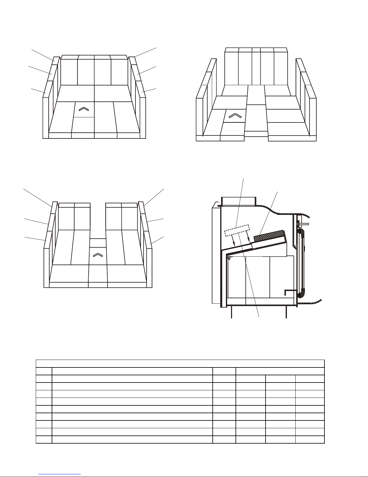
BRICK DIAGRAMS
ITEM DESCRIP TION PART #
CJW1000 CJW1500 CJW2000
1 FIRE BRICK LT 9"(229mm)x4-7/16"(113mm)x1-1/4"(32mm) S16040 11 12 15
2 FIRE BRICK LT-ANGLE CUT S16042 2 2
3 FIRE BRICK LT 7-1/4"(184mm)x4-7/16"(113mm)x1-1/4"(32mm) S16043 4 4
4 FIRE BRICK LT4-1/2"(114mm)x4-7/16"(113mm)x1-1/4"(32mm) S16046 1 1 1
5 FIRE BRICK LT 2-3/4"(70mm)x4-7/16"(113mm)x1-1/4"(32mm) S16224 1
6 FIRE BRICK LT 7-3/4"(197mm)x4-7/16"(113mm)x1-1/4"(32mm) S16222 4
7 FIRE BRICK LT 9"(229mm)x2-1/2"(64mm)x1-1/4"(32mm) S16216 1
8 BRICK FOR ASH DRAWER S16214 1 1 1
PARTS LIST
SERI ES
2
1
1 1
3 3
1
1
8
3
1
1 1
3
4
CJW 1000 SERIES
2
3 3 3
1
3
2
1
1
1
1
1
1
6
1 1
8
4
1
7
1
1
6
6
1
1
6
11
1
CJW 2000 SERIES
2 FULL BRICKS
2
BAFFLE ASSEMBLY
1
1
1 1 1
5
1
1
8
1 14
CJW 1500 SERIES
BE SURE TO INSTALL TWO
FULL BRICKS (S16040) IN
BAFFLE AS SHOWN
BAFFLE BRICK INSTALLATION
CJW 1000 AND CJW 1500 SERIES
6
 Loading...