

Century A-VMH36SD-1, A-VMH30SD-1, A-VMH18SU-1, B-VMH24SU-1, B-VMH18SU-1 Service Manual
...
Service Manual
VMH 9/12/18/24 SU Series
VMH 30/36 SD Series
Inverter Single Zone
Ductless Mini-Split
www.marsdelivers.com

CONTENTS
1. Precaution .......................................................................................................... 1
1.1 Safety Precaution ......................................................................................... 1
1.2 Warning ......................................................................................................... 1
2. Part Names and Functions ............................................................................... 3
2.1 Model Names of Indoor/Outdoor Units ......................................................... 3
2.2 Part Names of Indoor/Outdoor Units ............................................................ 4
3. Dimension .......................................................................................................... 5
3.1 Indoor Unit .................................................................................................... 5
3.2 Outdoor Unit ................................................................................................. 7
4. Refrigerant Cycle Diagram ............................................................................... 8
5 Wiring Diagram .................................................................................................. 9
6. Installation Details ............................................................................................. 9
6.1 Wrench Torque Sheet for Installation ............................................................ 9
6.2 Connnecting the Cables ............................................................................... 9
6.3 Pipe Length and the Elevation ...................................................................... 9
6.4 Initial Installation ......................................................................................... 10
6.5 Adding the Refrigerant After Running the System for Many Years ............. 10
6.6 Re-installation if the Indoor Unit Has Been Repaired ..................................11
6.7 Re-installation After Outdoor Unit Has Been Repaired ................................11
7. Operation Characteristics............................................................................... 13
8. Electronic Function ......................................................................................... 14
8.1 Abbreviation ................................................................................................ 14
8.2 Display Functions ....................................................................................... 14
8.3 Main Protection ........................................................................................... 15
8.4 Operation Modes and Functions ................................................................. 16
9. Troubleshooting .............................................................................................. 21
9.1 Indoor Unit Error Display ............................................................................ 22
9.2 Outdoor Unit Error Display .......................................................................... 23
9.3 Diagnosis and Solution ............................................................................... 26
10. Disassembly Instructions .............................................................................. 55
10.1 Indoor Unit................................................................................................. 55
10.2 Outdoor Unit .............................................................................................. 59

Service Manual - VMH 9/12/18/24 SU & VMH30/36S D Series
1. Precaution
1.1 Safety Precaution
To prevent injury and property
damage, these instructions must
be followed.
Incorrect operation due to
ignoring instructions will cause
harm or damage.
Before servicing the unit, be sure
to read service manual.
1.2 Warning
INSTALLATION
Do not use a defective or
underrated circuit breaker. Use this
appliance on a dedicated circuit.
There is risk of fire or electric shock.
For electrical work, contact the
dealer, seller, a qualified electrician,
or an authorized service center.
Do not disassemble or repair this
product, there is risk of fire or electric
shock.
Always ground this product.
There is risk of fire or electric shock.
Install panel and cover of control
box securely.
There is risk of fire or electric shock.
Always install a dedicated circuit
and breaker.
Improper wiring or installation may
cause electric shock.
Use the correctly rated breaker or
fuse.
There is risk of fire or electric shock.
Do not modify or extend the power
cable.
There is risk of fire or electric shock.
Do not install, remove, or reinstall
the unit by yourself (customer).
There is risk of fire, electric shock,
explosion, or injury.
Use caution when unpacking and
installing the product.
Sharp edges could cause injury, be
especially careful of the case edges
and the fins on the condenser and
evaporator.
For installation, always contact the
dealer or an authorized service
center.
Do not install this product on a
defective installation stand.
Be sure the installation area does
not deteriorate with age.
If the base collapses, the air
conditioner could fall with it, causing
property damage, product failure, and
personal injury.
Do not let the air conditioner run
for a long time when the humidity
is very high and a door or a
window is left open.
Take care to ensure that power
cable cannot be pulled out or
damaged during operation. There is
risk of fire or electric shock.
Do not place anything on the
power cable.
There is risk of fire or electric shock.
Do not plug or unplug the power
supply plug during operation.
There is risk of fire or electric shock.
Do not handle or touch the product
with wet hands.
Do not place a heater or other
appliance near the power cable.
There is risk of fire and electric shock.
Do not allow water to run into
electrical parts.
It may cause fire, failure of the
product, or electric shock.
Do not store or use flammable gas
or combustibles near this product.
There is risk of fire or failure of
product.
Do not use the product in a tightly
closed space for a long time.
Oxygen deficiency could occur.
When flammable gas leaks, turn off
the gas and open a window for
ventilation before turning the
product on.
If strange sounds or smoke come
from product, turn the breaker off
or disconnect the power supply
cable.
There is risk of electric shock or fire.
1

Service Manual - VMH 9/12/18/24 SU & VMH30/36S D Series
Stop operation and close the window
in storm or hurricane. If possible,
remove the product from the window
before the hurricane arrives.
There is risk of property damage, failure
of product, or electric shock.
Do not open the inlet grill of the
product during operation.
There is risk of physical injury, electric
shock, or product failure.
When the product is soaked, contact
an authorized service center. There is
risk of fire or electric shock.
Use caution that water does not
enter the product.
There is risk of fire, electric shock, or
product damage.
Ventilate the area from time to time
when operating this unit together
with a stove etc.
There is risk of fire or electric shock.
Turn the main power off when
cleaning or maintaining the product.
There is risk of electric shock.
When the product is not be used for
a long time, turn off the breaker.
There is risk of product damage or
failure, or unintended operation.
Take care to ensure that nobody can
step on or fall onto the outdoor unit.
This could result in personal injury and
product damage.
CAUTION
Always check for gas (refrigerant)
leakage after installation or repair of
product.
Low refrigerant levels may cause
failure of product.
Install the drain hose to ensure that
water is drained away properly.
A bad connection may cause water
leakage.
Keep level even when installing this
product.
It can avoid vibration or water leakage.
Do not install the product where
the noise or hot air from the
outdoor unit could affect
neighbors.
Use two or more people to lift and
transport the product.
Do not install the product where it
will be exposed to sea wind (salt
spray) directly.
It may cause corrosion on the
product. Corrosion, particularly on the
condenser and evaporator fins, could
cause product malfunction or
inefficient operation.
OPERATIONAL
Do not expose the skin directly to
cool air for long periods. (Do not
sit in the draft).
Do not use the product for
purposes such as preserving
foods, works of art, etc. It is a
consumer comfort air conditioner,
not a precision refrigeration
system.
There is risk of damage or loss of
property.
Do not block the inlet or outlet of
air flow.
Use a soft cloth to clean. Do not
use harsh detergents, solvents,
etc.
There is risk of fire, electric shock, or
damage to the plastic parts of the
product.
Do not touch the metal parts of the
product when removing the air
filter. They are very sharp.
Do not step on or put anything on
the product. (outdoor units)
Always insert the filter securely.
Clean the filter every two weeks or
more often if necessary.
A dirty filter reduces the efficiency of
the air conditioner and could cause
product malfunction or damage.
Do not insert hands or other
objects through air inlet or outlet
while the product is operating.
2

Service Manual - VMH 9/12/18/24 SU & VMH30/36S D Series
Do not drink the water drained from
the product.
Use a firm stool or ladder when
cleaning or maintaining the product.
Be careful and avoid personal injury.
Replace the all batteries in the
remote control with new ones of the
same type. Do not mix old and new
batteries or different types of
batteries.
There is risk of fire or explosion.
Do not recharge or disassemble the
batteries. Do not dispose of batteries
in a fire.
They may explode.
If the liquid from the batteries gets
onto your skin or clothes, wash it
well with clean water. Do not use the
remote if the batteries have leaked.
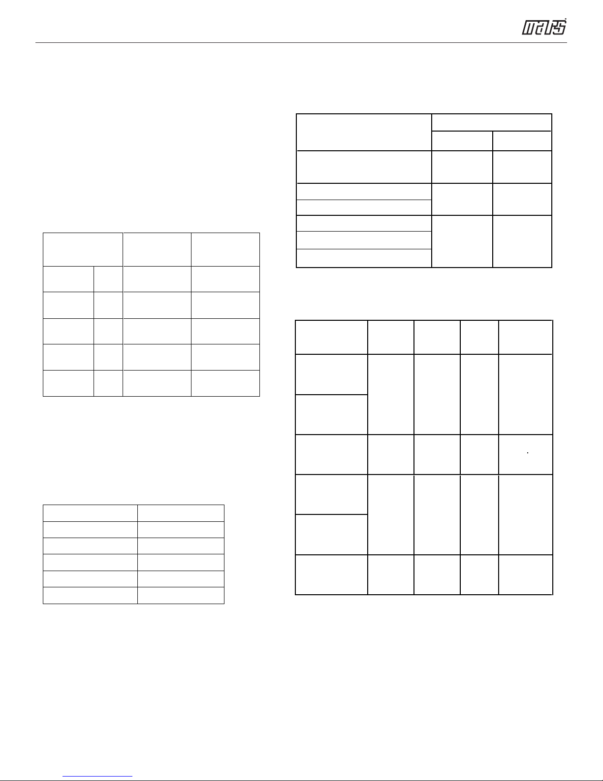
2. Part Names And Functions
2.1 Model Names of Indoor/Outdoor units
Series Capacity Indoor units
9k B-VMH09SU-1 A-VMH09SU-1
12k
18k
Inverter
24k
30k
36k
B-VMH12SU-1
B-VMH18SU-1 A-VMH18SU-1
B-VMH24SU-1 A-VMH24SU-1
B-VMH30SD-1 A-VMH30SD-1
B-VMH36SD-1 A-VMH36SD-1
Outdoor units
A-VMH12SU-1
3
Service Manual - VMH 9/12/18/24 SU & VMH30/36S D Series
2.2 Part names of Indoor/Outdoor units
4
Service Manual - VMH 9/12/18/24 SU & VMH30/36S D Series
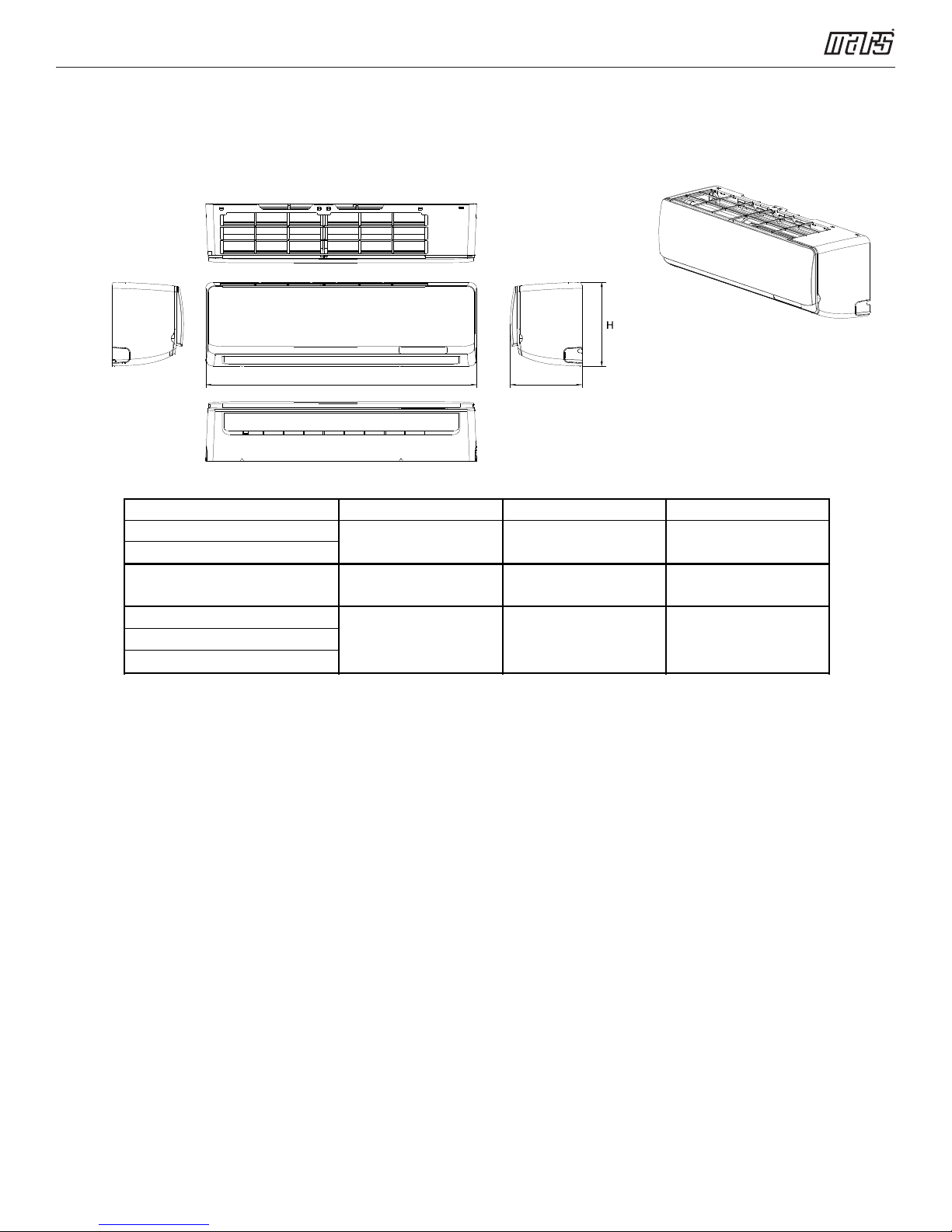
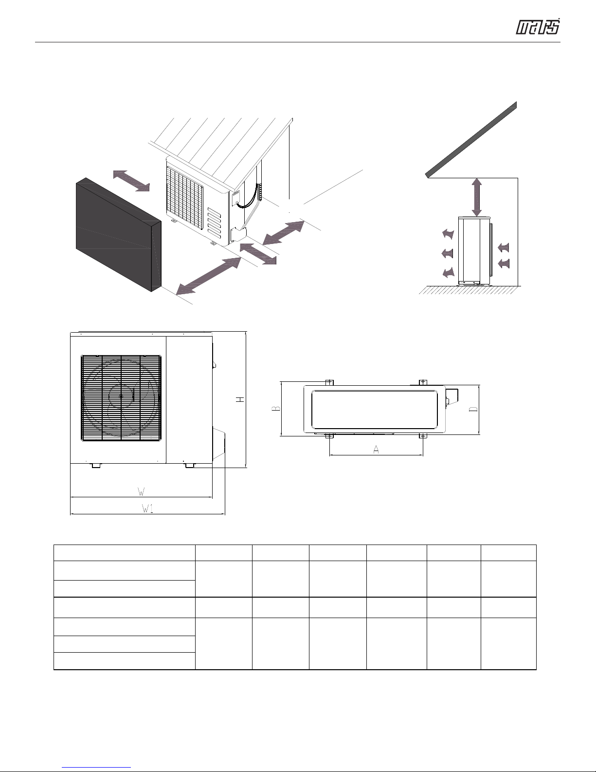
3. Dimension
3.1 Indoor Unit
W D
Model W D H
B-VMH09SU-1
(835mm)
32.9in
(198mm)
7.8in
(280mm)
11.0in
B-VMH12SU-1
B-VMH18SU-1
(990mm)
39.0in
(218mm)
8.6in
(315mm)
12.4in
B-VMH24SU-1
(1186mm )
46.7in
(258mm)
10.2in
(343mm)
13.5in
B-VMH30SD-1
B-VHH36SD-1
5
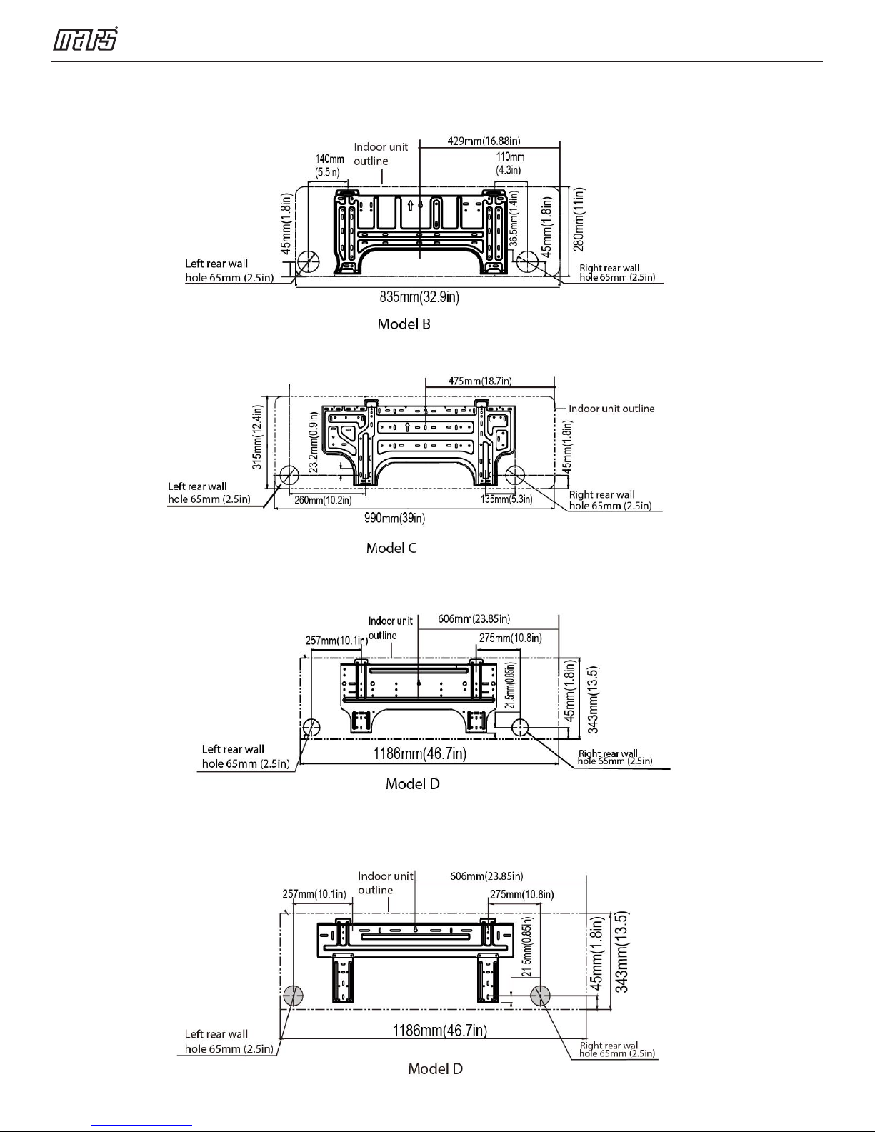
For B-VMH09SU-1, B-VMH12SU-1
For B-VMH18SU-1
Service Manual - VMH 9/12/18/24 SU & VMH30/36S D Series
For B-VMH24SU-1
For B-VMH30SD-1, B-VMH36SD-1
7
6
Service Manual - VMH 9/12/18/24 SU & VMH30/36S D Series
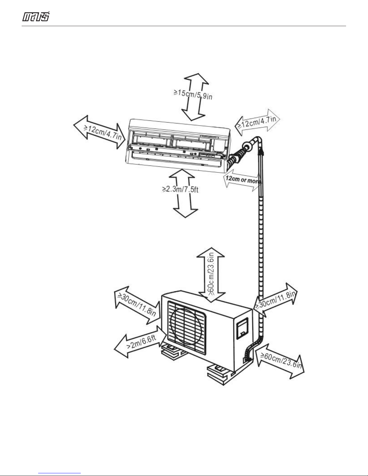
3.2 Outdoor Unit
More than 30cm(11.8in)
More than 30cm(11.8in)
Fe
n
c
e
o
o
b
s
r
t
a
c
l
e
s
More than 60cm(23.6in)
More than 70cm(27.6in)
More than 60cm(23.6in)
(Service space)
Note: The above drawing is only for reference. The appearance of your units may be different.
Model W in(mm) D in(mm) H in(mm) W1 in(mm) A in(mm) B in(mm)
A-VMH09SU-1
A-VMH12SU-1
A-VMH18SU-1
A-VMH24SU-1
A-VMH30SD-1
A-VMH36SD-1
31.5(800)
33.27(845) 14.29(363) 27.64(702)
37.24(946) 16.14(410) 31.89(810)
13.11(333) 21.81(554)
7
34.25(870) 20.24(514) 13.39(340)
35.98(914) 21.26(540) 13.78(350)
40.55(1030) 26.50(673) 15.87(403)
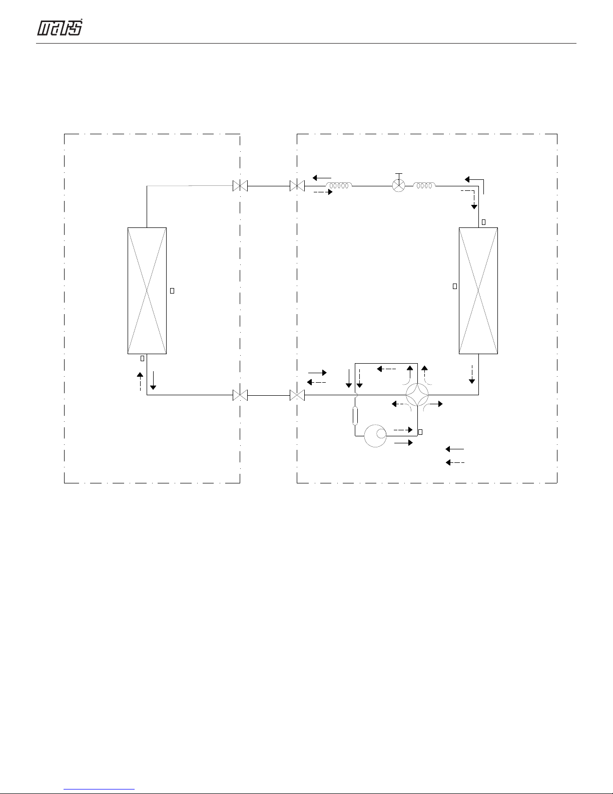
4. Refrigerant Cycle Diagram
INDOOR OUTDOOR
Service Manual - VMH 9/12/18/24 SU & VMH30/36S D Series
HEAT
EXCHANGE
(EVAPORATOR)
T2 Evaporator
temp. sensor
T1 Room temp.
sensor
LIQUID SIDE
2-WAY VALVE
GAS SIDE
3-WAY VALVE
CAPILIARY TUBE
Accumulator
Electronic
expansion valve
Compressor
CAPILIARY TUBE
T4 Ambient
temp. sensor
4-WAY VALVE
T5 Discharge
temp. sensor
T3 Condenser
temp. sensor
HEAT
EXCHANGE
(CONDENSER)
COOLING
HEATING
8
Service Manual - VMH 9/12/18/24 SU & VMH30/36S D Series
5. Wiring Diagram
(Please refer the wiring diagram on the unit)
6. Installation Details
6.1 Wrench torque sheet for
installation
Additional
Outside Diameter Torque
Ф6.35mm
Ф9.52mm
Ф12.7mm
Ф15.9mm
1/4in
3/8in
1/2in
5/8in
ll lb-ft
l8 lb-ft
25.8 lb-ft 26.5 lb-ft
33.2 lb-ft
Tightening
Torque
12 lb-ft
19 lb-ft
34.7 lb-ft
6.3 Pipe length and the elevation
Models
VMH09SU-1
VMH12SU-1
VMH18SU-1
VMH24SU-1
VMH30SD-1
VMH36SD-1
Models
A-VMH09SU-1
Standard
Length
(Ф 9.52mm)
(Ф 12.7mm)
(Ф 15.9mm)
Max.
Elevation
Pipe Size
Gas Liquid
3/8in
1/2in
5/8in
Max.
Length
A
1/4in
(Ф 6.35mm)
1/4in
(Ф 6.35mm)
3/8in
(Ф 9.52mm)
Additional
Refrigerant
Ф19mm
3/4in
47.9 lb-ft 49.4 lb-ft
6.2 Connecting the cables
The power cord should be selected according to the
following specifications sheet.
Appliance Amps AWG Wire Size
10 18
13 16
18 14
25 12
30 10
The cable size and the current of the fuse or switch
are determined by the maximum current indicated
on the nameplate which is located on the side
panel of the unit. Please refer to the nameplate
before selecting the cable, fuse and switch.
B-VMH09SU-1
A-VMH12SU-1
B-VMH12SU-1
A-VMH18SU-1
B-VMH18SU-1
A-VMH24SU-1
B-VMH24SU-1
A-VMH30SD-1
B-VMH30SD-1
A-VMH36SD-1
B-VMH36SD-1
7.5m
(24.6ft)
7.5m
(24.6ft)
7.5m
(24.6ft)
7.5m
(24.6ft)
10m
(32.8ft)
20m
(65ft)
25m
(82ft)
30m
(82.0ft)
25m
(82.0ft)
30m
(98ft)
50m
(164ft)
65m
(213ft)
15g/m
(0.16oz/ft)
15g/m
(0.16oz/ft)
30g/m
(0.32oz/ft)
30g/m
(0.32oz/ft)
9
Service Manual - VMH 9/12/18/24 SU & VMH30/36S D Series
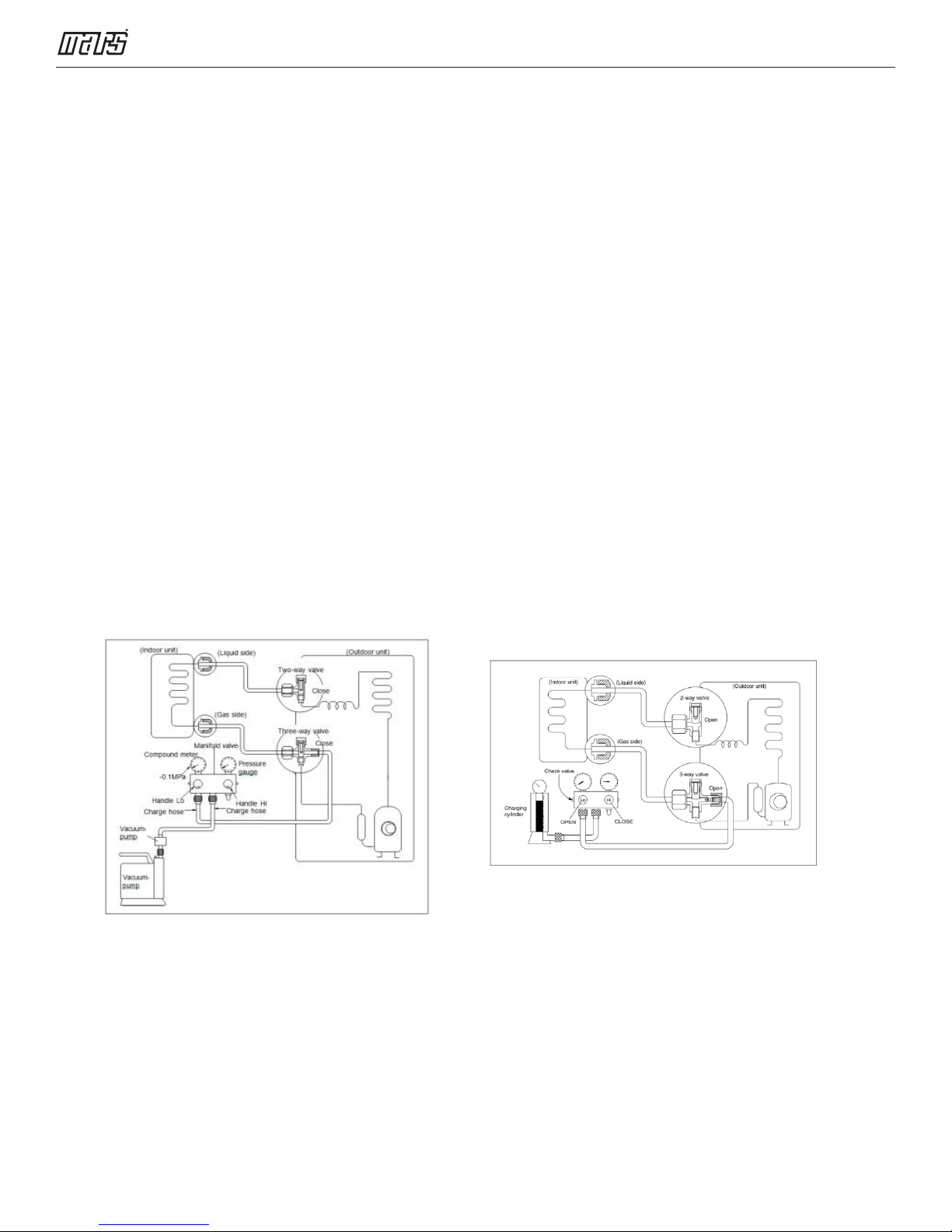
6.4 Initial Installation
Air and moisture in the refrigerant system have
undesirable effects as below:
Pressure in the system rises.
Operating current rises.
Cooling or heating efficiency drops.
Moisture in the refrigerant circuit may
freeze and block capillary tubing.
Water may lead to corrosion of parts
in the refrigerant system.
Therefore, the indoor unit and the pipes
between indoor and outdoor units must be
leak tested and evacuated to remove gas and
moisture from the system.
Gas leak check (soap and water method):
Apply soap water or a liquid neutral detergent
on the indoor unit connections or outdoor unit
connections by a soft brush to check for
leakage of the connecting points of the piping.
If bubbles form, the pipes have leakage.
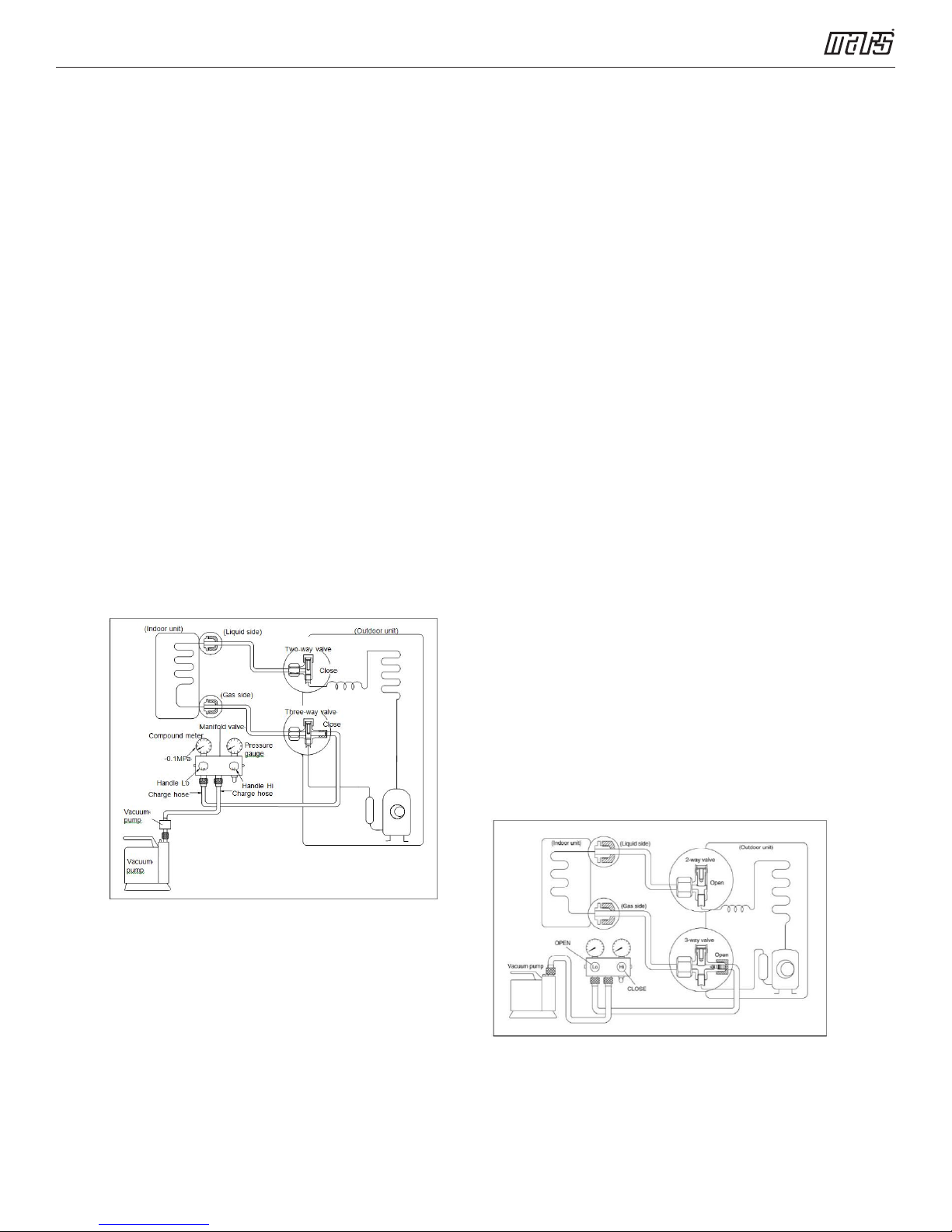
5) Evacuate for 30 minutes and check that
micron gauge reads <500 microns. If not, it
should be pumped 20 minutes more. If the
pressure can’t achieve <500 microns after
pumping 50 minutes, please check for
leakage points. Fully close the handle valve
of the low pressure manifold set and stop the
operation of the vacuum pump. Confirm that
the gauge needle does not move above 500
microns (approximately 5 minutes after
turning off the vacuum pump).
6) Turn the flare nut of the 3-way valves about
45° counterclockwise for 6 or 7seconds after
the gas coming out, then tighten the flare nut
again. Make sure the pressure display in the
pressure indicator is a little higher than the
atmosphere pressure. Then remove the
charge hose from the 3-way valve.
7) Fully open the 2-way valve and 3-way valve
and securely tighten the cap of the 3-way
valve.
1. Air purging with vacuum pump
1) Completely tighten the flare nuts of the
indoor and outdoor units, confirm that both
the 2-way and 3-way valves are set to the
closed position.
2) Connect the low pressure charge hose to
the 3-way valve's gas service port.
3) Connect the high pressure hose to the
vacuum pump.
4) Fully open the handle of the low pressure
manifold valve.
6.5 Adding the refrigerant after running
the system for many years
Procedure
1) Connect the charge hose to the 3-way
service port, open the 2-way valve and the
3-way valve. Connect the charge hose to
the valve at the bottom of the cylinder. Turn
the cylinder bottom up to ensure liquid
charge.
2) Purge the air from the charge hose. Open
the valve at the bottom of the cylinder and
press the check valve on the charge set to
purge the air (be careful of the liquid
refrigerant).
10
Service Manual - VMH 9/12/18/24 SU & VMH30/36S D Series
3) Put the charging cylinder onto the electronic
scale and record the weight.
4) Operate the air conditioner in the cooling
mode.
5) Open the valves (Low side) on the charge set
and charge the system with liquid refrigerant.
6) When the electronic scale displays the proper
weight (refer to the gauge and the pressure
of the low side), disconnect the charge hose
from the 3-way valve’s service port
immediately and turn off the air conditioner
before disconnecting the hose.
7) Mount the valve stem caps and the service
port. Use torque wrench to tighten the
service port cap to a torque of 13F.P.
Be sure to check for gas leakage.
6.6 Re-installation if the indoor unit has
been repaired
1. Air purging with vacuum pump
5) Operate the vacuum pump to evacuate.
6) Evacuate for 30 minutes and check
whether the compound meter indicates
500 microns. If the meter does not indicate
500 microns after pumping 30 minutes, it
should be pumped 20 minutes more. If the
pressure can’t achieve 500 microns after
pumping 50 minutes, please check for
leakage points. Fully close the low
pressure valve of the manifold and stop the
operation of the vacuum pump. Confirm
that the gauge needle does not move
(approximately 5 minutes after turning off
the vacuum pump).
7) Turn the flare nut of the 3-way valves
about 45° counterclockwise for 6 or 7
seconds after the gas coming out, then
tighten the flare nut again. Make sure the
pressure display in the pressure indicator
is a little higher than the atmosphere
pressure. Then remove the charge hose
from the 3-way valve.
8) Fully open the 2-way valve and 3-way
valve and securely tighten the cap of the
3-way valve.
1) Completely tighten the flare nuts of the
indoor and outdoor units, confirm that both
the 2-way and 3-way valves are set to the
closed position.
2) Connect the low pressure charge hose to
the 3-way valve's gas service port.
3) Connect the high pressure charge hose to
the vacuum pump.
4) Fully open the low pressure handle of the
manifold.
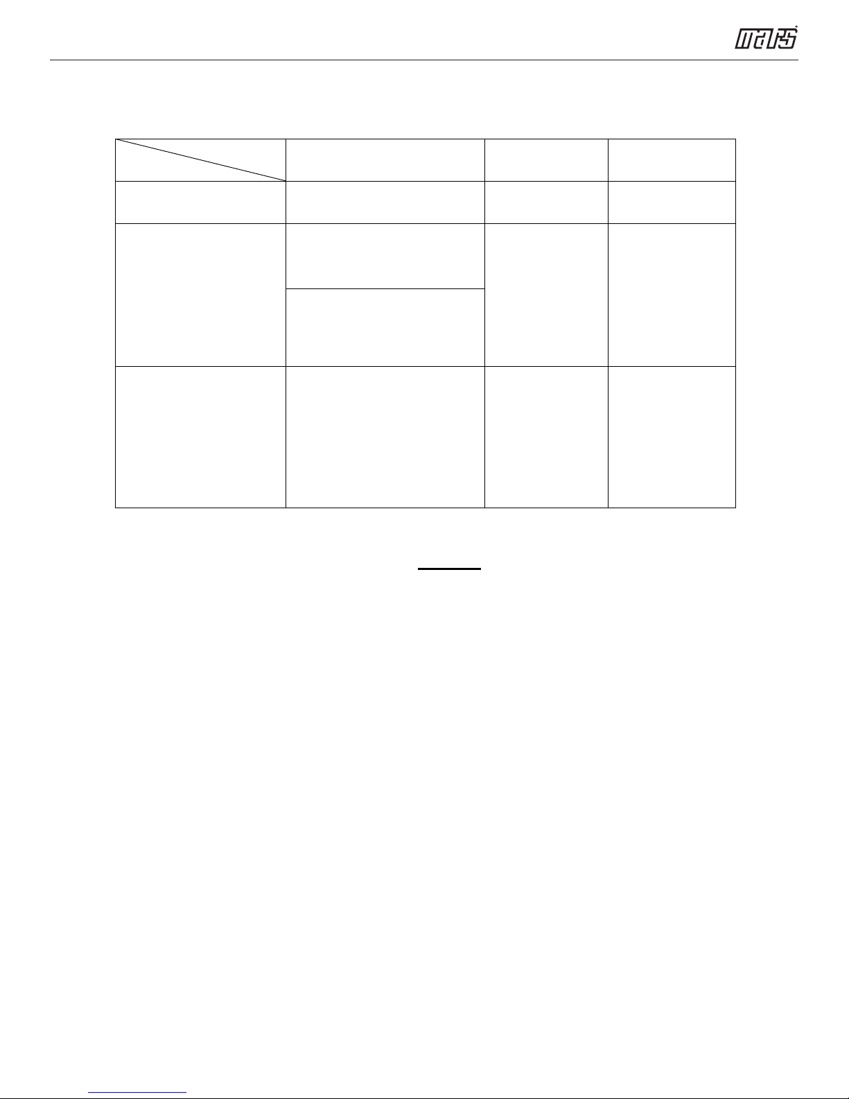
6.7 Re-installation after outdoor unit
has been repaired
1. Evacuation for the whole system
11
Service Manual - VMH 9/12/18/24 SU & VMH30/36S D Series
Procedure:
1) Confirm that both the 2-way and
3-way valves are set to the opened
position.
2) Connect the vacuum pump to 3-way
valve’s service port.
3) Evacuate for approximately one hour.
Confirm that the compound meter
indicates <500 microns.
4) Close the valve (Low side) on the
charge set, turn off the vacuum pump,
and confirm that the gauge needle
does not move (approximately 5
minutes after turning off the vacuum
pump).
5) Disconnect the charge hose from the
vacuum pump.
2. Refrigerant charging
Procedure:
1) Connect the charge hose to the charging
cylinder, open the 2-way valve and the 3-
way valve. Connect the charge hose
which you disconnected from the vacuum
pump to the valve at the bottom of the
cylinder. Turn the cylinder bottom up to
ensure liquid charge.
2) Purge the air from the charge hose. Open
the valve at the bottom of the cylinder and
press the check valve on the charge set
to purge the air (be careful of the liquid
refrigerant).
3) Put the charging cylinder onto the
electronic scale and record the weight.
4) Open the valves (Low side) on the charge
set and charge the system with liquid
refrigerant. If the system cannot be
charged with the specified amount of
refrigerant, or can be charged with a little
at a time (approximately 5oz. each time),
while operating the air conditioner in the
cooling cycle, wait approximately one
minute and then repeat the procedure.
5) When the electronic scale displays the
proper weight, disconnect the charge
hose from the 3-way valve’s service port
immediately. If the system has been
charged with liquid refrigerant while
operating the air conditioner, turn off the
air conditioner before disconnecting the
hose.
6) Mount the valve stem caps and the
service port. Use torque wrench to tighten
the service port cap to a torque of 13F.P.
Be sure to check for gas leakage.
12
Service Manual - VMH 9/12/18/24 SU & VMH30/36S D Series
7. Operation Characteristics
Mode
Room temperature
Outdoor temperature
VMH30SD-1
VMH36SD-1
Outdoor temperature
VMH09SU
VMH12SU
VMH18SU
VMH24SU
Temperature
Cooling operation Heating operation Drying operation
17℃~32℃
(62℉~90℉)
0
~50°C
°C
~122°F)
(32
°F
°C
~50
°C
°C
-15°C~50
(5°F~122°F)
(need low ambient cooling function)
-30
(-22°F~122°F)
0℃~30℃
(32℉~86℉)
°C
-15
~30
(5°F~86°F)
-30
~30
°C
(-22°F~86
°C
°C
°F
(32
)
(32
10℃~32℃
(50℉~90℉)
°C
0
~50°C
~122°F)
°F
0
~50°C
°C
~122°F)
°F
+32
CAUTION:
1. If the air conditioner is used beyond the above conditions, certain safety protection features
may come into operation and cause the unit to operate abnormally.
2. The room relative humidity should be less than 80%. If the air conditioner operates beyond
this figure, the surface of the air conditioner may attract condensation. Please set the vertical air
flow louver to its maximum angle (vertically to the floor), and set HIGH fan mode.
3. The optimum performance will be achieved during this operating temperature zone.
13
Service Manual - VMH 9/12/18/24 SU & VMH30/36S D Series
8. Electronic Function
8.1 Abbreviation
T1: Indoor room temperature
T2: Coil temperature of evaporator
T3: Coil temperature of condenser
T4: Outdoor ambient temperature
TP: Compressor discharge temperature
8.2 Display function
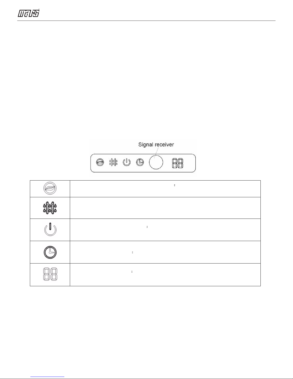
8.2.1 Icon explanation on indoor display board.
ION indication lamp (optional function):This lamp illuminates when Clean
Air feature is activated.
DEFROST indication lamp: Lights up when the air conditioner starts defrosting
automatically or when the warm air control feature is activated in heating operation.
OPERATION indication lamp:This lamp illuminates when the air conditioner is in
operation.
TIMER indication lamp:Lights up during Timer operation.
Temperature indicator:Displays the temperature settings when the air conditioner
is operational. Displays the malfunction code.
14

Service Manual - VMH 9/12/18/24 SU & VMH30/36S D Series
8.3 Main Protection
8.3.1 Three minutes delay at restart for
compressor
Less than one minute delay for the first time
start-up and a three minute delay for others.
8.3.2 Temperature protection of compressor
top
The unit will stop working when the compressor
top temp. protector cuts off, and will restart after
the compressor top temp. protector restarts.
8.3.3 Temperature protection of compressor
discharge
Compressor discharge temp. TP >115°F
(239°F) for 5s, compressor stops.
8.3.4 Fan speed is out of control
When Indoor fan speed runs too low
(300RPM) or too high (1500RPM) for a pre-
determined time, the unit will stop and the LED
will display the failure
8.3.7 Compressor preheating functions
Preheating permitting condition:
When T4 (outdoor ambient temperature) <3°C
(37.4°F), the preheating function will be
activated.
8.3.8 Zero crossing detection error
protection
If AC detects time interval is not correct for
continuous 240s, the unit will stop and the LED
will display the failure. The correct zero
crossing signal time interval should be between
6-13ms.
8.3.9 Sensor protection at open circuit and
breaking disconnection.
When there is only one temperature sensor in
malfunction, the air conditioner will keep
working but show the error code, in case of any
emergency use.
When there is more than one temperature
sensor in malfunction, the air conditioner will
stop working.
8.3.5 Inverter module protection
The Inverter module has a protection function
for current, voltage and temperature. If these
protections happen, the corresponding code
will display on indoor unit and the unit will stop
working.
8.3.6 Indoor fan delayed open function
When the unit starts up, the louver will be active
immediately and the indoor fan will open 10
seconds later.
If the unit runs in heating mode, the indoor fan
will also be controlled by anti-cold wind
function. Fan will turn on, low speed, at 87°F
coil temperature. Fan will switch to high speed
at 114°F coil temperature.
8.3.10 Refrigerant leakage detection
This function is only active in cooling mode. It
can better prevent the compressor being
damaged by refrigerant leakage or
compressor overload.
Open condition:
When compressor is active, the value of the
coil temperature of evaporator T2 has no
change, or very little change.
15
Service Manual - VMH 9/12/18/24 SU & VMH30/36S D Series
8.4 Operation Modes and Functions
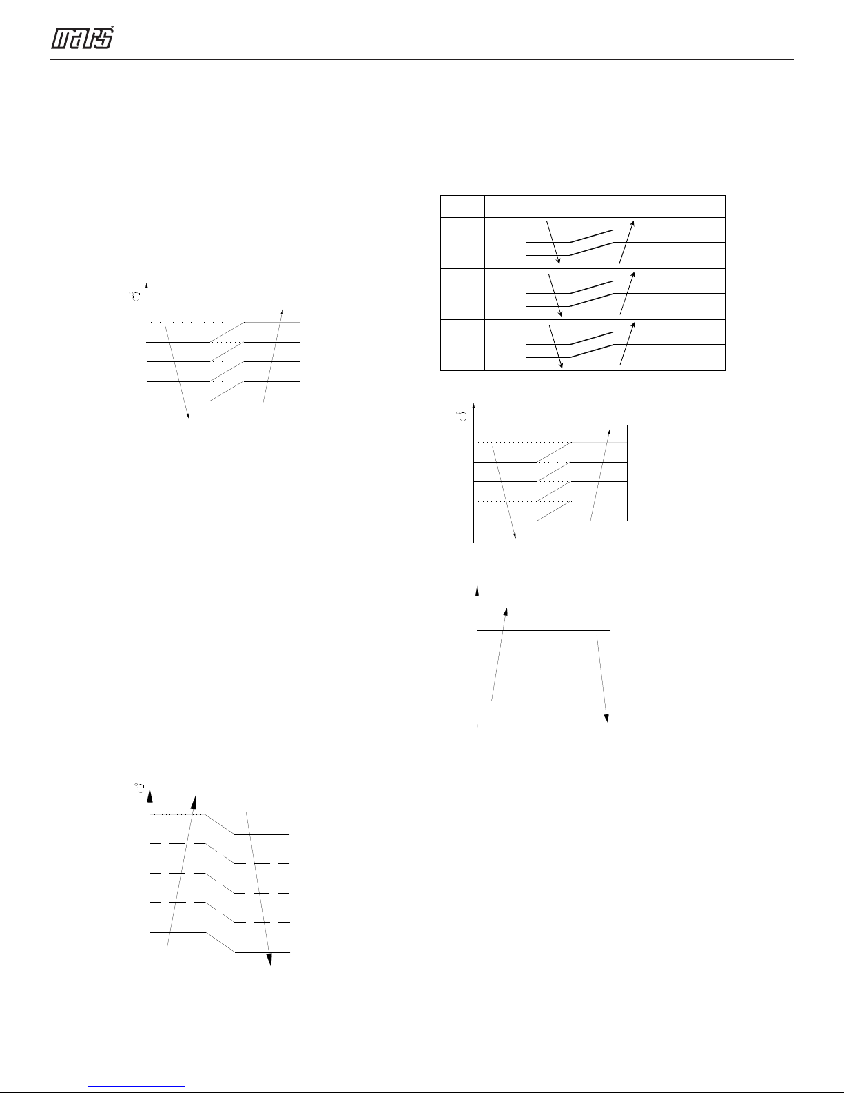
8.4.1 Fan mode
1) Outdoor fan and compressor stop.
2) Temperature setting function is disabled,
and no setting temperature is displayed.
3) Indoor fan can be set to high/med/low/auto.
4) The louver operates same as in cooling
mode.
5) Auto fan:
T1
a
b
c
d
e
8.4.2 Cooling Mode
8.4.2.1 Compressor running rules
When T1-Ts<-2℃(28.4°F), the compressor will
stop, when T1—T
compressor will be activated.
When the AC runs in mute mode, the
compressor will run at low frequency. When
the current is more than set value, the current
protection function will be activated, and the
compressor will stop.
>-0.5℃(31.1°F), the
S
medium, low and auto.
When the setting temp. is reached, if the
compressor stops running, indoor fan motor
will run in Minimum speed or set speed. The
indoor fan is controlled as below:
Setting fan
speed
H
M
L
T1-Td ℃(°F)
A H(=H)
B
C
D M(M=M)
E
F
G L(L=L)
H
I
Actual fan speed
H+(H+=H+G)
H-(H-=H-G)
M+(M+=M+Z)
M-(M-=M-Z)
L+(L+=L+D)
L-(L-=L-D)
The auto fan acts as below rules:
T1
a
b
c
d
e
8.4.2.4 Condenser temperature protection
T3
Off
Decrease
8.4.2.2 Outdoor fan running rules
The outdoor unit will be run at different fan
speeds according to T4.
For different outdoor units, the fan speeds are
different.
T 4
A+
A
B
C
D
E
8.4.2.3 Indoor fan running rules
In cooling mode, indoor fan runs all the time
Hold
Resume
When condenser temperature temp. is
more than setting value, the compressor will
stop.
8.4.2.5 Evaporator temperature protection
When Evaporator temperature is less than
setting value, the compressor will stop.
8.4.3 Heating Mode
8.4.3.1 Compressor running rules
When T1-Ts>-ΔT, the compressor will stop,
when T1-T
<ΔT-1.5,the compressor will be
S
on.
ΔT is the programmed parameter of
16
Service Manual - VMH 9/12/18/24 SU & VMH30/36S D Series
When the AC runs in mute mode, the
compressor will run with low frequency. When
the current is more than set value, the current
protection function will be activated and the
compressor will stop.
8.4.3.2 Outdoor fan running rules
The outdoor unit will be run at different
fan speeds according to T4.
For different outdoor units, the fan speeds are
different.
T4
E
D
C
B
A
A+
8.4.3.3 Indoor fan running rules
When the compressor is on, the indoor fan can
be set to high/med/low/auto/mute.
When indoor unit coil temp. is low, the anti-cold
air function will start and indoor fan motor will
run at low speed, the speed can’t be changed,
when the temp. is lower than setting value, the
indoor fan motor will stop.
When the indoor temp reaches the setting
temp., the compressor will stop, the indoor fan
motor will run at the minimum speed or setting
speed. (The anti-cold air function is valid). The
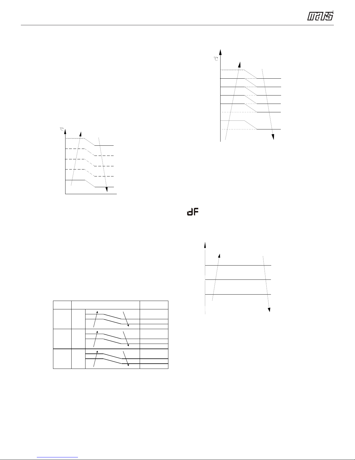
indoor fan is controlled as below:
Setting fan
speed
H
M
L
T1-Td
℃
Actual fan speed
H-(H-=H-G)
)
H(=H
H+(H+=H+G)
M-(M-=M-Z)
M(M=M)
M+(M+=M+Z)
L-(L-=L-D)
L(L=L)
L+(L+=L+D)
Auto fan action in heating mode:
T1-Td+ΔT
8.4.3.4 Defrosting mode
AC will enter the defrosting mode according to
the value of temp. of T3 and the value range of
temp. change of T3 and also the compressor
running time.
During the defrosting mode, the compressor
keeps running, indoor and outdoor motor will
stop, defrost lamp of the indoor unit will be lit.
“ .” Will be displayed.
8.4.3.5 Evaporator coil temperature
protection
Off
Decrease
Hold
Resume
When evaporator temperature temp. is more
than the setting protection value, the compressor
will stop.
8.4.4 Auto-mode
This mode can be chosen with remote controller
and the setting temperature can be changed
between 17°C(62.6°F)~30°C(86°F). In auto
mode, the machine will choose cooling, heating
or fan-only mode according to ΔT.
17
Service Manual - VMH 9/12/18/24 SU & VMH30/36S D Series
(ΔT =T1-Ts).
T1-Ts
Cooling
Fan only
Heating*
Heating*:
Indoor fan will run at auto fan of the
relevant mode.
The louver operates same as in relevant mode.
If the machine switches mode between heating
and cooling, the compressor will stop and then
choose mode according to T1-Ts.
If the setting temperature is modified, the
machine will choose running function again.
8.4.5 Drying mode
8.4.5.1 Indoor fan speed is fixed at breeze and
can’t be changed. The louver angle is the
same as in cooling mode.
8.4.5.2 Low indoor room temperature
protection In drying mode, if room temperature
is lower than 10°C(50°F), the compressor will
stop and not resume until room temperature
exceeds 12°C(53.6°F).
8.4.5.3 Evaporator anti-freezing protection,
condenser high temperature protection and
outdoor unit frequency limit are active and the
same as that in cooling mode.
In forced auto, forced cooling or any other
operation mode, pressing touch button will turn
off the machine.
8.4.6.2 In forced operation mode, all general
protections and remote control are available.
8.4.6.3 Operation rules:
Forced cooling mode:
The compressor runs at F2 frequency and
indoor fan runs as breeze. After running for 30
minutes. the machine will turn to auto mode as
24°C(75.2°F) setting temperature.
Forced auto mode:
The action of forced auto mode is the same as
normal auto mode with 24°C(75.2°F) setting
temperature.
8.4.7 Auto-Restart function
The indoor unit is equipped with auto-restart
function, which is carried out through an autorestart module. In case of a sudden power
failure, the module memorizes the setting
conditions before the power failure. The unit
will resume the previous operation setting (not
including swing function) automatically after 3
minutes when power returns.
If the memorization condition is forced cooling
mode, the unit will run in cooling mode for 30
minutes and turn to auto mode as 24°C(75.2°
F) setting temp.
If AC is off before power off and AC is required
to start up now, the compressor will have 1
minute delay when power on. Other conditions,
the compressor will have 3 minutes delay
when restarting.
8.4.5.4 The outdoor fan operates the same as
in cooling mode.
8.4.6 Forced operation function
8.4.6.1 Enter forced operation function:
When the machine is off, pressing the touch
button will carry the machine to forced auto
mode. If pressing the button once again within
5 seconds, the machine will turn into forced
cooling mode.
8.4.8 Refrigerant Leakage Detection
With this new technology, the display area will
show “EC” when the outdoor unit detects
refrigerant leakage.
8.4.9 8°C Heating (optional)
When the compressor is running, the indoor
fan motor will run without anti-cold air function.
When the compressor is off, the indoor
fan motor is off.
18
Service Manual - VMH 9/12/18/24 SU & VMH30/36S D Series
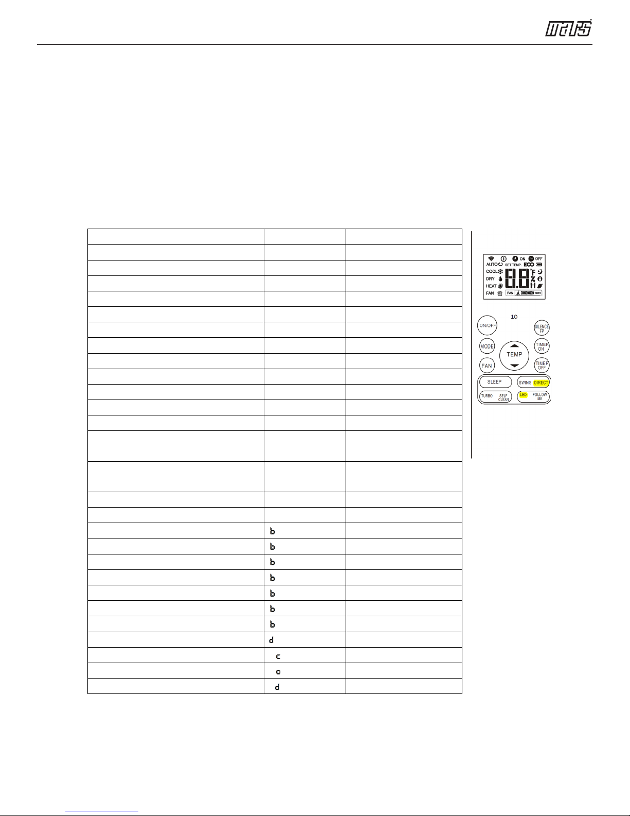
8.4.10 Point check function
Press the LED DISPLAY or LED or MUTE button of the remote controller three times, and then
press the AIR DIRECTION or SWING button three times in ten seconds, the buzzer will sound
for two seconds. The air conditioner will enter into the information inquiry status. You can
press the LED button, then DIRECT button to check the next or front item’s information. When
the AC enters the “information inquiry” status, it will display the code name
details are as follows.
Enquiry information Displaying code Meaning
T1 T1 T1 temp.
T2 T2 T2 temp.
T3 T3 T3 temp.
T4 T4 T4 temp.
T2B Tb T2B temp.
TP TP TP temp.
TH TH TH temp.
Targeted Frequency FT Targeted Frequency
Actual Frequency Fr Actual Frequency
Indoor fan speed IF Indoor fan speed
Outdoor fan speed OF Outdoor fan speed
EXV opening angle LA EXV opening angle
Compressor continuous running time CT Compressor continuous
Causes of compressor stop. ST Causes of compressor
Reserve A0
Reserve A1
Reserve 0
Reserve 1
Reserve 2
Reserve 3
Reserve 4
Reserve 5
Reserve 6
Reserve L
Reserve A
Reserve U
Reserve T
running time
stop.
in 2 seconds, the
19
Service Manual - VMH 9/12/18/24 SU & VMH30/36S D Series
When the AC enters into the information inquiry status, it will display the following code values
during the next 25s
Enquiry
Display value Meaning Remark
information
T1,T2,T3,T4,
T2B,TP,TH,
Targeted
Frequency,
Actual
Frequency
-1F,-1E,-1d,-1c,-
1b,-1A
-19—99 -19—99
A0,A1,…A9 100,101,…109
b0,b1,…b9 110,111,…119
c0,c1,…c9 120,121,…129
d0,d1,…d9 130,131,…139
E0,E1,…E9 140,141,…149
F0,F1,…F9 150,151,…159
Indoor fan
speed /
0 OFF
1,2,3,4 Low speed, Medium
Outdoor fan
speed
14-FF
.
-25,-24,-23,-22,-21,-2
0
1. Display temperature is actual value.
2. Temperature is °C no matter what kind
of remote controller is used.
3. T1,T2,T3,T4,T2B display range:-25~70,
TP display range:-20~130.
4. Frequency display range: 0~159HZ.
5. If the actual value exceeds the range, it
will display the maximum value or
minimum value.
For some big capacity motors.
speed, High speed,
Turbo
Actual fan speed =
Display value turns
to decimal value and
then multiply 10. The
For some small capacity motors,
display value is from 14-FF(hexadecimal),
the corresponding fan speed range is from
200-2550RPM.
unit is RPM.
EXV opening
0-FF
angle
Compressor
0-FF 0-255 minutes If the actual value exceeds the
continuous
running time
Causes of
0-99 For the detailed
compressor
stop.
Reserve 0-FF
Actual EXV opening
value = Display
value turns to
decimal value and
then multiply 2.
range, it will display the maximum
value or minimum value.
Decimal display
meaning, please
consult with engineer
20
Service Manual - VMH 9/12/18/24 SU & VMH30/36S D Series
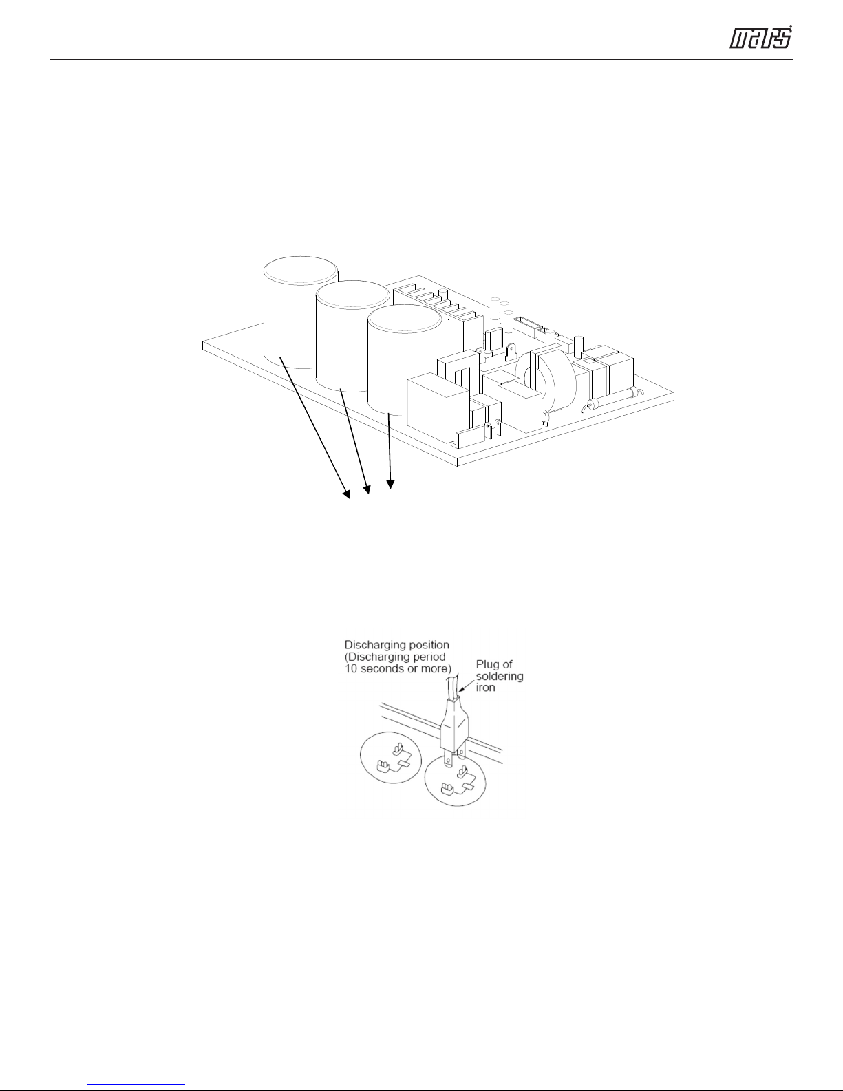
9. Troubleshooting
Safety
An electric charge is still kept in capacitors even when the power supply is shut off. Do not forget to discharge the
electricity in capacitor.
Electrolytic Capacitors
(HIGH VOLTAGE! CAUTION!)
For other models, please connect discharge resistance (approx.100Ω 40W) or soldering iron (plug) between +, -
terminals of the electrolytic capacitor on the contrary side of the outdoor PCB.
Note: The picture above is only for reference. Your plug may be different.
21
9.1 Indoor Unit Error Display
Service Manual - VMH 9/12/18/24 SU & VMH30/36S D Series
Operation
lamp
☆ 1 time
☆ 2 times
☆ 3 times
☆ 4 times
☆ 5 times
☆ 6 times
☆ 7 times
☆ 1 times
☆ 2 times
☆ 3 times
☆ 4 times
Timer lamp Display LED STATU S
X E0 Indoor unit EEPROM parameter error
X E1 Indoor / outdoor units communication error
X E2 Zero-crossing signal detection error
X E3 Indoor fan speed has been out of control
X E4
X E5
Indoor room temperature sensor T1 open circuit or short
circuit
Evaporator coil temperature sensor T2 open circuit or
short circuit
X EC Refrigerant leakage detection
O F0 Overload current protection
O F1
O F2
O F3
Outdoor ambient temperature sensor T4 open circuit or
short circuit
Condenser coil temperature sensor T3 open circuit or
short circuit
Compressor discharge temperature sensor TP open
circuit or short circuit
☆ 5 times
☆ 6 times
☆ 1 times ☆
☆ 2 times ☆
☆ 3 times ☆
☆ 4 times ☆
☆ 5 times ☆
☆ 7 times ☆
O F4 Outdoor unit EEPROM parameter error
O F5 Outdoor fan speed has been out of control
P0 IPM malfunction or IGBT over-strong current protection
P1 Over voltage or over low voltage protection
P2 High temperature protection of IPM module
P3* Outdoor ambient temperature too low.
P4 Inverter compressor drive error
P6 Low pressure protection(Only for 36K)
O(light) X(off) ☆(flash)
*P3
1) In heating mode, when the outdoor temperature is lower than -13°F for 1 hour, the indoor
unit display error code P3.
2) If the outdoor temperature is higher than -7.6°F for 10 minutes and compressor stop for 1 hour
or outdoor temperature is higher than 23°F for 10 minutes, then the unit will return to work.
* Fault Symptom:
The display board shows a garbled code or a code that is not an error code found in the service
manual nor a temperature reading.
Troubleshooting:
Use the remote controller. If the unit does not respond to the remote, the indoor PCB needs to be
replaced; if the unit does respond, then the display board needs to be replaced.
22
 Loading...