

Page 1
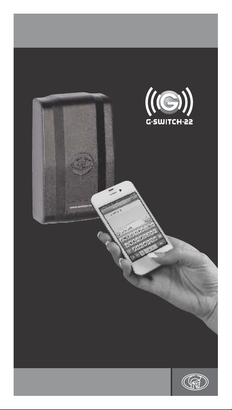
G-SWITCH-22 2G GSM Module
Programming Guide
TM
Centurion Systems (Pty) Ltd
www.CentSys.com
Page 2

1. Programming the G-SWITCH-22
Multi-user Capability (1200 phone numbers)
It is important to note that the memory of the G-SWITCH-22 2G GSM
Module is limited to 1200 authorised phone numbers. In other words, a
maximum of 1200 phone numbers can be registered on the system at any
one time. Each phone number can be configured uniquely with respect to
Inputs and Outputs, as well as activation and notification messages. Each
phone number can also be assigned a limited number of uses for each
Output.
When the memory limit is reached, trying to add new phone numbers will
not overwrite or affect the existing numbers stored into the system, it will
just not be possible to add the additional numbers.
Special Functionality
The G-SWITCH-22 offers various advanced and useful features which can
be easily set up via SMS or using the G-WEB online user interface.
These features are intended to enhance the Module’s capabilities and offer
the user more flexibility in applying the Module as a full monitoring and
control solution.
Below appears a list of the G-SWITCH’s advanced features as well as a
definition of each.
&
Sticky Latches: The Module’s Outputs can be configured to
&
Filter Time: Filter Time determines how long an Input event
&
Blanking Time: Blanking Time determines how long the unit will
&
Event Count: This refers to how many Input events must occur
&
All Pass Mode: When enabled, this useful mode allows any number
&
Permitted The G-SWITCH-22 allows for time-periods to be
Access Mode specified during which a specific user's phone
(Recurring number will be valid and will be allowed to activate
Weekly) the unit's outputs via Missed Call or SMS.
Any activation from the user initiated outside of the
specified time-period will be ignored.
For instance, a user can be granted access between
8:00 and 17:00, Monday to Friday and his access
barred from activating the outputs after hours and
during weekends
&
Permitted In this mode, an administrator can specify two
Access Mode time-based parameters between which a number
(Once off) will be valid. This is ideal for guesthouse and Bed
and Breakfast owners, as it enables them to set
‘remember’ their state between power cycles.
For instance, if Output 2 was active, i.e. the relay
in an energised state, and the power is removed,
when power is reapplied Output 2 will return to the
activated state. This functionality is referred to as a
‘sticky latch’ and can be enabled or disabled.
Sticky latches don’t apply to pulsed Outputs and
are enabled by default
(rising or falling edge) must be present before it is
recognised, i.e. an SMS is sent. The time is set in
increments of one second and the default is 0
wait between events before it will recognise the
next event
before it is recognised and an SMS notification is
sent to users
that gives the Module a Missed Call to activate the
Outputs, irrespective of whether they are learned
into memory. A typical application would be an
event such as a wedding where many guests need
to be given temporary access. Instead of manually
learning in a 100 guests and then having to delete
them again after the occasion, the administrator
can simply enable All Pass Mode and disable it
again afterwards
specific arrival and departure dates and times and
allow access to guests based on these
time-dependent limits. This feature and only be
activated via G-Web
2. In a Hurry?
To simply add a phone number to the Module to trigger Output 1, with
the default pulse time activated through a Missed Call, send the following
SMS to the Module: p.xxxx.ap.yyyyyyyyyy, where xxxx is the system
password (default is 1234¹), and yyyyyyyyyy is the phone number you
wish to add.
1. For your own security, it is recommended that the default password
be changed and that the SIM PIN code protection is enabled once
the unit has been configured.
(see CO. ‘Configuring the Module’)
Ensure that a record of your system password is kept in a safe place.
Record system password here
Ensure that a record of the new SIM PIN number is kept in a safe place.
Record new SIM PIN here
3. Command Structure
Programming commands are sent to the Module using a standard text
message (SMS).
The command structure must always take the following form:
p.xxxx.command1.parameter1.parameter2 command2.
parameter1.parameter2, etc.
Page 3

All commands must start with ‘p.xxxx’, where xxxx is a user-
defined four-digit password. The default password is 1234.
For security purposes, this should be changed on commissioning.
&
Each command and parameter must be separated by
a period (.)
&
Commands can be concatenated (linked), and must be
separated by a space ( )
&
The maximum message length is limited to 160 characters
&
Commands are not case-sensitive
4. Command Overview
Description
(Password)
P
System
password
(Add Phone)
Add a phone
AP
number to the
system
(Delete Phone)
Delete a phone
DP
number from the
system
(Edit Phone)
EP
Edit a phone
(Airtime)
AT
Loads or queries
airtime
(Airtime)
ACK
Loads or queries
airtime
(Query Phone)
Query phone
QP
settings
(Configuration)
Configure Inputs,
CO
Outputs and
system settings
Parameters
Four-digit password
Phone number(s) (up to 19 digits each).
Output to be activated by a Missed Call or
SMS (O U1/OU2)
Input to be monitored (IN1/IN2)
Sub parameters
User Limit UL (1–65536 activations)²
Output text string (user-configured messages 1-20)
Input text string (user-configured messages 1-20)
2. A user limit restricts the number of
times a Missed Call will activate the unit.
Once the user limit is reached, the phone
number will automatically be deleted from
the system
Phone number (up to 19 digits)
OU1 Activates Output 1
DOU1 Deletes Output 1
OU2 Activates Output 2
DOU2 Deletes Output 2
IN1 Activates Input 1
DIN1 Deletes Input 1
IN2 Activates Input 2
DIN2 Deletes Input 2
DIN1S Deletes Input 1 string
DIN2S Deletes Input 2 string
DOU1S Deletes Output 1 string
DOU2S Deletes Output 2 string
Load airtime (L)
Query airtime (Q)
Sub-parameters
Airtime voucher number
If you add a ‘space’ and then the text ‘ACK’
to the end of any command, you will receive
an SMS back confirming that the command
has been received by the Module. For
example, p.xxxx.DP.0841234567 AC K
Phone number (up to 19 digits)
OU1PU Sets Output 1 as pulsed
OU1LA Sets Output 1 as latched
OU1PT Sets Output 1 pulse time in
OU2PU Sets Output 2 as pulsed
OU2LA Sets Output 2 as latched
OU2PT Sets Output 2 pulse time in
SS Requests Signal strength
CS Changes SIM card P IN number
EP Enables SIM card P IN checking
DP Disables SIM card PIN checking
SP Sets SIM PI N in memory only
QF Queries the Firmware version
QS Queries the Module settings
NP New system password
BE Backs up EEPRO M
RE Restores EEPROM
IO Input/Output mappings
QB Queries the battery voltage
CL Clears the transaction logs
REBO OT Reboots the Module
SLE Enables sticky latches
SLD Disables sticky latches
RSL Resets sticky latches
STR Sets the string number and
ATE Enables the automatic hourly
ATD Disables the automatic hourly
INxR Makes the selected Input rising
INxF Makes the selected Input falling
INxB Makes both of the selected Input
INxBT Sets the selected Input Blanking
milliseconds
milliseconds
associated text
airtime query
airtime query
edge active
edge active
edges active
Time
Page 4

Description
(Configuration)
Configure Inputs,
CO
Outputs and
system settings
Parameters
INxFT Sets the selected Input Filter Time
INxEC Sets the Input event counter
LM List all the messages stored in
the system; up to 20 messages
are allowed
Reset.all Resets all settings on the Module
Reset.usr Resets User Data on the Module
Reset.con Resets Configuration Data on the
APME Enables All Pass Mode so that any
AMPD Disables All Pass Mode
IMEI Retrieves the Module's IMEI
number
ENABLE Enables the unit
DISABLE Disables the unit
PCMS This command configures the
Module to react to free
Please Call Me messages,
either from any learn-in phone
number, or from a specific
authorised user.
(Maximum message length is
19 characters)
Sub-parameters
Pulse time: In milliseconds
New PIN: Four digits
New
password: Four digits
IO Mapping
Blanking
Time: In seconds
Filter Time: In seconds
Event count: Numeric value
Module
number that gives the Module a
Missed Call will activate the Outputs
5. Setting a New System Password
Command Description
p.xxxx.CO.NP.
yyyy
Reset to the Factory Default Settings
In the event that you forget the system password you will need to reset
the Module to the Factory Default settings. To do this, please follow the
steps below:
1. Power down the Module.
2. Bridge the following terminals: IN1, IN2 and GND.
3. Short out the defaulting pads by touching across them with the tip
of a screwdriver.
4. Power up the Module.
5. Remove the bridges to the terminals as mentioned in point 2 and 3
above, as well as the defaulting pads.
6. The Module will now be reset to the Factory Default settings.
All of the information on the Module will be erased.
yyyy is the new password
STR. Programming Input and Output
Text Strings
The system allows the user to pre-program up to 20 text messages
(of 25 characters each); the user can then associate messages with
specific actions such as the activation of an Output or as an Input
notification message. Each message is assigned a number, between
1 and 20, by the user and when an Input is configured to send
notifications, or an Output configured to be activated via SMS, the user
must specify what message number that Input/Output will use.
To configure text strings for Output activation and Input notification,
send the following command to the Module:
p.xxxx.CO.S TR.y.‘‘text string’’, where ‘xxxx’ represents the password
and ‘y’ represents the memory slot – between 1 and 20 – to which the
text string should be assigned in the system’s memory.
The text between the double inverted commas is the command that will
be sent to the Module in order to activate an Output, or the text that will
appear on the user’s mobile phone screen when the associated Input is
activated.
Text strings are allocated to specific Outputs or Inputs by means of the
following command structure:
p.xxxx.AP.phone number.O Uz.‘‘y’’.INz.‘‘y’’. In this instance, ‘‘xxxx’’
again represents the password, ‘‘z’’ is the number of the
Input/Output to which one wishes to assign a text string, and ‘‘y’’ is
the text string slot in the system’s memory.
Examples
&
p.xxxx.CO.S TR.1.‘‘pump active’’
This command will configure text string ‘‘1'’ as ‘‘pump active’’.
&
p.xxxx.CO.S TR.5.‘‘tan'k full’’.STR.6.‘‘tank empty’’
Configures text string 5 as ‘‘tank full’’ and text string 6 as
‘‘tank empty’’.
&
P.xxxx.CO.S TR.3.‘‘Open gate’’
This command configures text string 3 as ‘‘Open gate’’. The ‘‘Open
gate’’ command would be used to activate an output, the next
example illustrates this.
&
p.xxxx.AP.0821234596.O U1.‘‘3’’
Adds phone number 0821234596 to the system and enables
Output 1 to be activated by an SMS. To activate the Output,
either SMS the text stored in memory location 3 to the Module, or
use the Output activation command p.xxxx.OU.OU1on
Page 5

&
p.xxxx.AP.0823359981.O U2.‘‘10’’.IN1R.‘‘3’’.IN1F.‘‘4’’
Adds phone number 0823359981 to the system and configures
Output 2 to be activated by text string 10, Input 1 to send an
SMS with text string 3 on rising edge activation and the same
Input to send an SMS with text string 4 on falling edge activation.
In such a case, text string 3 would typically be something like
‘‘power off’’ and text string 4 could be ‘‘power back on’’.
For your convenience, a template has been provided below which can
be used to note down which text strings have been associated with
which number in the system’s memory. It is also possible to query the
Module as to which messages are saved in its memory by sending the
following command:
p.xxxx.co.lm, where ‘‘xxxx’’ represents the system password.
Message number
1.
2.
3.
4.
5.
6.
7.
8.
9.
10.
11.
12.
13.
14.
15.
16.
17.
18.
19.
20.
Message text string
(max. 25 character including spaces)
AP. Adding a Phone
This command allows new phone numbers to be added to the system.
When adding a new phone, it is possible to specify which Outputs are to
be activated by a Missed Call from the phone, and which Inputs will
cause a message to be sent to the phone. The number of times the
phone can be used to activate the system can also be specified.
Description Parameters
Phone number(s) (up to 19 digits each)
Output to be activated by a Missed Call or SMS
(Add phone)
Add a phone
AP
number to the
system
Examples (Commands have been highlighted for clarity)
Command Description
p.xxxx.AP.0841
234567
p.xxxx.AP.0841
234567.OU2
p.xxxx.AP.0841
234567.OU2.”5”
p.xxxx.AP.0845
632347.OU1.
UL20. “7"
p.xxxx.AP.0841
234567.OU1.
OU2
p.xxxx.AP.0841
234567.083765
4321.OU1
(OU1/OU2)
Input to be monitored (IN1/IN2)
Sub-parameters
User Limit UL (1 – 65536 activations)
Output text string (user-configured messages 1-20)
Input text string (user-configured messages 1-20)
Adds phone number 0841234567 to the system and,
since no parameters are specified, by default
assigns Output 1 to be activated by a Missed Call
from this number. This allows easy addition of new
phones to a basic system.
Adds phone number 0841234567 to the system,
and assigns Output 2 to be activated by a
Missed Call from this number.
Adds phone number 0841234567 to the system,
and assigns Output 2 to be activated by sending
user-configured message number 5.
When programming the Output to be
activated by a specific text string, the text
string number MUST begin and end with
double quotation marks (” “). The quotation
marks (” “) are only required when
programming - they must not be included
when sending the text message to activate
the Output.
Adds phone number 0841234567 to the system,
and assigns Output 1 to be activated by sending
user-configured message number 7 with a user
limit of 20 uses. After 20 SMSs (activations),
this number will automatically be deleted from the
system, but only if the number has no other
functionality associated with it.
Adds phone number 0841234567 to the system,
and assigns both Output 1 and Output 2 to be
activated by a Missed Call from this number.
Adds phone numbers 0841234567 and 0837654321
to the system, and assigns Output 1 to be activated
by a Missed Call from either of these numbers.
The number of phone numbers that can be added
in one command is limited only by the maximum
allowed message length (160 characters).
Page 6

Adds phone number 0841234567 to the system,
and assigns Output 1 to be activated by a Missed
p.xxxx.AP.08412
34567.OU1.UL5
p.xxxx.AP.0841
234567.OU1.
UL25.OU2
p.xxxx.AP.0841
234567.OU1.
UL25.OU2.
UL100
p.xxxx.AP.0844
332211.ou1.ou
2.‘‘9”.IN1r.‘‘2”.
IN1f.‘‘1”
Call from this number, with a limit of five uses.
After five Missed Calls (activations), this number
will automatically be deleted from the system,
but only if the number has no other functionality
associated with it.
Adds phone number 0841234567 to the system,
and assigns both Output 1 and Output 2 to be
activated by a Missed Call from this number.
Output 1 has a limit of 25 uses. After 25 Missed
Calls (activations), Output 1 will no longer be
activated by a Missed Call. However, Output 2 will
continue to function indefinitely.
Adds phone number 0841234567 to the system,
and assigns both Output 1 and Output 2 to be
activated by a Missed Call from this number.
Output 1 has a limit of 25 uses, and Output 2 has
a limit of 100 uses. After 25 Missed Calls
(activations), Output 1 will no longer be activated
by a Missed Call. However, Output 2 will continue
to function for a further 75 calls. Thereafter, this
number will automatically be deleted from the
system.
This command produces the following Output:
&
A Missed Call from this number will trigger
Output 1
&
Output 2 is enabled for SMS and will be
triggered by message number 9
&
A rising edge on Input 1 will send message
number 2
&
A falling edge on Input 1 will send message
number 1
DP. Deleting a Phone
This command allows one or more numbers to be deleted from
the system
Description Parameters
(Delete Phone)
DP
from the system
Phone number(s) (up to 19 digits)
Examples (Commands have been highlighted for clarity)
Command Description
p.xxxx.DP.0841
234567
p.xxxx.DP.0841
234567.08376
54321.082776
6554
Deletes phone number 0841234567 from the
system
Deletes phone numbers 0841234567, 0837654321
and 0827766554 from the system
EP. Editing a Phone
This command allows the functionality of a phone to be edited.
It is useful when a number has been added with the wrong
functionality, or when circumstances have changed.
Description Parameters
(Edit phone)
EP
Edit phone
Phone number(s) (up to 19 digits each)
OU1 Activates Output 1
DOU1 Deletes Output 1
OU2 Activates Output 2
DOU2 Deletes Output 2
IN1 Activates Input 1
DIN1 Deletes Input 1
IN2 Activates Input 2
DIN2 Deletes Input 2
DIN1S Deletes Input 1 string
DIN2S Deletes Input 2 string
DOU1S Deletes Output 1 string
DOU2S Deletes Output 2 string
Sub-parameters
Output text string (user-configured message)
Input text string (user-configured message)
QP. Querying a Phone
This command allows the functionality of a phone in the system
to be queried. Information for that phone, including what
Outputs and Inputs are active, text strings and limited uses
counters will be sent in a text message to the querying phone.
Description Parameters
(Query Phone)
Query phone
QP
settings
(Query Phone
Master) Returns
QPM
the master phone
number
Phone number(s) (up to 19 digits)
Page 7

Examples (Commands have been highlighted for clarity)
Command Description
p.xxxx.QP.0841
234567
Queries phone number 0841234567. Phone settings
are sent via SMS to the querying device.
AT. Airtime
This command allows an airtime voucher to be loaded,
or remaining airtime to be queried.
Description Parameters
(Airtime)
AT
Loads or queries
airtime
Load airtime (L)
Query airtime (Q)
Sub-Parameters
Airtime voucher number
Examples (Commands have been highlighted for clarity)
Command Description
p.xxxx.AT.L.123
4567890
p.xxxx.AT.Q
Loads airtime voucher number 1234567890 onto
the SIM.
Airtime remaining on the SIM is sent via S MS to
the querying device.
CO. Configuring the Module
This command allows the functionality of the system to be
configured. Outputs can be set up, states of Input/Outputs
checked, PINs and passwords managed, etc.
Examples (Commands have been highlighted for clarity)
Command Output configuration
p.xxxx.CO.OU1PU.
OU1PT .2000
p.xxxx.CO.OU1LA.
OU2PU .OU2P T.
1500
p.xxxx.CO.SS
p.xxxx.CO.QB
p.xxxx.CO.CL
Sets Output 1 as pulsed, and sets Output 1
pulse time to two seconds (2000 milliseconds).
Sets Output 1 as latched, sets Output 2 as
pulsed, and sets Output 2 pulse time to 1.5
seconds (1500 milliseconds).
Sends an SMS to the querying phone with a
value of 5 (strongest) to 1 (weakest) for signal
strength.
Sends an SMS to the querying phone with the
battery voltage value.
Clears all the transaction logs stored in the
system’s memory.
p.xxxx.CO.DSL
p.xxxx.CO.ESL
p.xxxx.CO.STR.1.
‘‘alarm
activated”.STR.5.
“power failed”
p.xxxx.CO.STR.18.
‘‘open gate”
p.xxxx.CO.IN1R
p.xxxx.CO.IN2B
p.xxxx.CO.IN2BT.4
p.xxxx.CO.IN1FT.2
p.xxxx.CO.IN2EC.3
p.xxxx.CO.LM
Disables sticky latches, so that when the Module’s
power is cycled, the Outputs will return to their
default state and will not assume the state they
were in prior to the power cycle.
Enables sticky latches, so that when the Module’s
power is cycled, the Output relays assume the
state they were in prior to the power cycle.
Configures text string 1 as “alarm activated” and
text string 5 as “power failed”. If, for instance,
these text strings are assigned to certain Inputs,
an SMS containing this text will be sent to users
upon activation of the Inputs associated with
them.
Configures text string 18 as “open gate”. The text
string “open gate” (without quotation marks) can
be SMSd to the Module and used to activate an
Output.
Configures Input 1 to send an SMS if a rising
edge signal is present.
Configures Input 2 to send SMSs on both rising
and falling edge activation.
Sets Input 2 to only become active and send an
SMS once four seconds have elapsed since the
previous trigger.
Sets Input 2 to become active and send an SMS
only if the Input has been valid for two seconds.
Sets Input 1 to send an SMS only if it has been
triggered three times.
Sends an SMS to the querying phone with a list
of all the messages stored in the system.
A. SIM card PIN Code Settings
Command Description
p.xxxx.CO.CS.
yyyy
p.xxxx.CO.EP
p.xxxx.CO.DP
Change the SIM card PIN code. yyyy is the NEW
PIN code.
Enable checking of the SIM PI N number on
startup.
Disable checking of the SIM PIN number on startup.
Page 8

Setting the new SIM PIN number in memory only
p.xxxx.CO.SP.
yyyy
(Useful when a new SIM is going to be inserted in
the future. On startup, the Module will
automatically try this PIN if the old PIN does not
work). yyyy is the new PIN number. The old PIN
number does not have to be entered.
B. Query Firmware version
Command Description
p.xxxx.CO.QF
Sends an SMS to the querying phone with the
Module’s firmware version.
C. Query controller status/settings
Command Description
Sends an SMS to the querying phone with the
following information:
&
Current state of the Outputs
&
p.xxxx.CO.QS
Current state of the Inputs
&
Output configuration (Pulsed/Latched)
&
Output pulse times
&
Input-Output mappings
&
IP address and port of host server
D. Backing up and Restoring the Memory
The following commands require an optional Memory Backup
Module (Product code PCA12201V1.0). See Section 6 of the
Pocket Installation Guide for location of Backup Module port
Command Description
Back up the entire Module memory (EEPROM) onto a
Backup Memory Module.
p.xxxx.CO.BE
p.xxxx.CO.RE
This includes all user information and Module settings.
The Memory Backup Module must be in place before
the command is sent to the Module. After sending the
command, a confirmation SMS will be sent back
indicating whether the backup was successful or not.
Restore the entire Module memory (EEPROM) from a
Backup Memory Module.
This includes all user information and Module settings.
The Backup Memory Module must be in place before
the command is sent to the Module.
After sending the command, a confirmation SMS will
be sent back indicating whether the restore was
successful or not.
E. Mapping Inputs to Outputs
Allows activation and deactivation of Input-Output
mappings. If an Input is mapped to an Output, and that
Input is activated, the mapped Output will also activate,
responding according to its configuration settings:
IN1OU1: Maps Input 1 to Output 1
p.xxxx.CO.I O.
IN1OU2: Maps Input 1 to Output 2
IN2OU1: Maps Input 2 to Output 1
IN2OU2: Maps Input 2 to Output 2
DIN1OU1: Deletes Input 1 to Output 1 mapping
DIN1OU2: Deletes Input 1 to Output 2 mapping
DIN2OU1: Deletes Input 2 to Output 1 mapping
DIN2OU2: Deletes Input 2 to Output 2 mapping
F. Clearing Memory
Command Description
Resets the entire Module. All user information is
p.xxxx.CO.reset.all
p.xxxx.CO.reset.usr
p.xxxx.CO.reset.con
deleted, and all Module settings are restored to
Factory Default.
Deletes all user information on the Module.
Module settings are not affected.
Resets all Module settings to Factory Defaults.
User information is not affected.
G. Alternative SMS Activation of Outputs
Even though a preconfigured SMS text may have been assigned
to Outputs when adding a phone to the system, the Outputs on
the Module can also be explicitly activated by sending an SMS to
the Module.
For added convenience and flexibility, the system does allow
numbers that have not been learned into memory to activate
Outputs via SMS; however, this functionality is passwordprotected and the owner of the originating number will have to be
in possession of the system password in order to activate Outputs
in this manner.
Outputs can be activated with one of the commands below:
&
OU.OU 1on Output command --- Output 1 on
&
OU.OU 2on Output command --- Output 2 on
&
OU.OU 1off Output command --- Output 1 off
&
OU.OU 2off Output command --- Output 2 off
&
OU.OU1on2off Output command --- Output 1 on and 2 off
&
OU.OU2on1off Output command --- Output 2 on and 1 off
&
OU.allon Output command --- both Outputs on
&
OU.alloff Output command --- both Outputs off
Example
&
p.1234.OU.OU2ON Switches Output 2 on
Page 9

Examples
Command Description
Activates Output 1. If OU1 is set as pulsed, the
p.xxxx.OU.OU1on
p.xxxx.OU.OU2off
Output will activate for the configured pulse time If
OU1 is set as latched, it will turn on and remain on.
Deactivates Output 2. If OU2 is set to pulsed, the
command will have no effect. If OU2 is set to
latched, and currently on, it will turn off.
H. Please Call Me Activations
This function will ONLY trigger Relay 1
Examples
Command Description
Configures the Module so that a Please Call Me
p.xxxx.CO.PCMS.
”Please call”
p.xxxx.CO.PCMS.
”call
0811234678”
message from any authorised phone number will
activate Output 1. The incoming please call me
SMS must contain the "Please call" text in order to
trigger output 1.
Configures the Module so that a Please Call Me
message from a specific authorised phone number,
in this case 0811234678, will activate Output 1.
The incoming please call me SMS must contain the
"call 08112345678" text in order to trigger output 1.
Tips and Tricks
&
You can use the text ‘‘me’’ instead of specifying your own number
when adding, deleting, editing or querying your phone.
For example, p.xxxx.AP.me
&
If you make a mistake during the programming via a mobile phone,
you will receive an ‘error’ SMS to let you know
The Module must have sufficient airtime credit to send the SMSs.
Page 10

Connect with us on:
facebook.com/CenturionSystems
YouTube.com/CenturionSystems
@askCenturion
Subscribe to the newsletter: www.CentSys.com/Subscribe
Call Centurion Systems (Pty) Ltd South Africa
Head Office: +27 11 699 2400
Call Technical Support: +27 11 699 2481
from 07h00 to 18h00 (UTC+2)
E&OE Centurion Systems (Pty) Ltd reserves
the right to change any product without prior notice
All product and brand names in this document that are accompanied by
the ® symbol are registered trademarks in South Africa and/or
other countries, in favour of Centurion Systems (Pty) Ltd, South Africa.
The CENTURION and CENTSYS logos, all product and brand names in
this document that are accompanied by the TM symbol are trademarks
of Centurion Systems (Pty) Ltd, in South Africa and other territories;
all rights are reserved.
We invite you to contact us for further details.
0.07.D.0044_22042015_ENG
www.CentSys.com
 Loading...