


@~§~&lJ@~§
~&~U:JJ&[b
SERIES
100
PRINTERS
JULY 1975
Centronics
No.
37400001
Rev.
C
I:EnTRDnll:S
data computer corp.
HUDSON, NEW
TELEPHONE
HAMPSHIRE
(603)
883
03051
- 0111

TABLE
OF CONTENTS
Page
INTRODUCTION
.......
UNPACKING/REPACKING PROCEDURES
SET-UP PROCEDURES
OPERATING NOTES
OPERATING
OPERATOR CONTROLS
LOADING
GUIDE
PAPER
AND
INDICATORS
TOP OF FORM ADJUSTMENT
FORMS THICKNESS CONTROL
VERTICAL
VERTICAL
FORMAT
FORMAT
UNIT
TAPE
RIBBON REPLACEMENT .
RIBBON
AND
PAPER SPECIFICATIONS
RIBBON REPLACEMENT DIAGRAMS
SPECIAL CONTROL CODES . . .
STANDARD
CHARACTER
SETS
...
USASCII CODE
.
2
3
· 4
4
· 5
6
6
_
•.
.
. Back
Back
7
8
9
· 10
.10
·
11
·
12
Cover
Cover
I:EnTROnll:S
CENTRONICS
HUDSON. N.H. 03051
TELEPHONE (603) 883-0111
(710) 228-6505/TELEX 94-3404
TWX
EASTERN REGION: (617) 272-8545 (MASS.)
CENTRAL
WESTERN REGION: (714) 979-6650 (CALIF.)
CENTRONICS
MISSISSAUGA. ONTARIO (416) 625-0770
CENTRONICS
BRUSSELS. BELGIUM (02) 762-3572
CENTRONICS
DORADO, PUERTO RICO (809)
DATA
COMPUTER
REGION: (513) 294-0070 (OHIO)
DATA
COMPUTER (CANADA) LTD
INTERNATIONAL
OF
PUERTO RICO, INC.,
CORP.
CORP.,
796-1881
.•
©Copyright
A
II
Patents pending in
1975 Centronics Data Computer Corp.
rights reserved
USA and
other
countries

Scope
INTRODUCTION
This manual contains instructions reiating
to
the installation and operation
of
all
Centronics' Series 100 printers. This includes uncrating and set-up procedures, operating instructions and
other
reference information useful
to
the printer operator.
General Description
The Centronics Series
matrix techniques for character generation. Each
100 printers are medium speed, impact printers which use
is
a completely self-contained unit which
dot
includes the mechanical and electro-mechanical components, control logic, character pattern
generator,
single line buffer (132 characters) and power suppiy.
Available models include:
(a) Model 101 - The basic printer, prints 132-column lines at 165 characters per
second.
(b) Model
- Similar
to
the Model 101, but with additional features such
as
lOlA
paper runaway inhibit, manual line feed switch, remote select/deselect, etc.
(c) Model 101AL - Functionally the same
as
the
lOlA,
but
uses more compact
electronics packaging.
(d) Model
.2, .3,
101S - Prints standard O.l-inch characters
.4
and .7 -inch high) symbols, using .1-inch
blocks.
(e)
Model 102A - Prints at twice the speed
heads.
(f) Model 102AL - Functionally the same
ics
packaging.
is
specified on a nameplate located on the back
The
model number
electron
as
well
as
large-scale (e.g.,
dot
patterns
of
the
101 A by
as
the 1 02A, but uses more compact
of
the printer.
as
building
using two print

UNPACKING/REPACKING
Tools you may use:
17mm Socket Wrench
Adjustable Wrench
or
Tinsnips
wire-cutters
UNPACKING
1.
Cut the two bands
2.
Lift
top
of
crate (2) up straight.
(1
)(strapping) around crate.
3. Remove plastic cover from printer.
4.
Remove nuts (3), washers (4), springs (5) from
long bolts (8).
5.
Lift printer
6.
Remove bolts (12) and washers (11) from
bottom
off
pallet (10).
of
platform (7).
PROCEDURES
PRINTER
MUST
BE
COMPLETELY
REMOVED FROM ALL PALLETS
7. Remove elastic retain
(a)
Head
Exercise Caution -
stress on
(see diagram
(b) Paper
(c)
Ribbon Spool right side
8. See SET
the
on
Tractor
UP
PROCEDURE.
ing
bands from:
Do
not place
Video Amplifier
next
page)
Units
PC
any
Board
REPACKING
9. To repack, reverse the uncrating procedure
steps 2 through 6 and add new strapping
around the crate.
in
2

COMPLETE ENTIRE UNPACKING PROCEDURES PRIOR TO
1.
Note any discrepancies in general
2.
Thread
the
enclosed pin feed locking
the
pin feed
stacker
four
The left pin feed
treme
lift
3.
head
up head clears
length
CAN
ANCE
4.
Open
through
insert
pin feed gates.
Adjust
5.
ity as follows: 1) Loosen lock
increase head
control
prior
head(s) across
penetration
on
the
smudging
knob(s).
units
and
attach
(shipped separately)
screws
taken
from
the
unit
should
left
side.
front
cover
and
from
left
of
the
BE
DAMAGED IF
OR
IF
OPTIC HEAD
the
right
the
opening
the
paper
head
penetration
to
right. Ensure
the
timing
fence.
Caution:
and
left
at
in
the
manually move
pin feed gates, feed
the
penetration
knob(s);
to
(Note:
shipping); 2) Manually move
the
paper
until smudging occurs; 3) Back
penetration
(Approx
just
..
006
PERFORMING
appearance.
knobs
the
paper
guide
to
printer
guide
be
fence over
THERE
IS
MISALIGNED.
top
pin feed units. Close
for
optimum
knob(s)
by
turning
This
knob
and
keep increasing
to
the
in.); 4)
using
mounting
locked
at
holes.
the
the
that
optic
the
entire
TIM ING FENCE
IS
NO
CLEAR-
of
the
printer
print
and
slightly
penetration
is
preset
the
point
Hghten
of
the
SET-UP PROCEDURES
THE
into
and
the
ex-
print
pick-
paper
and
the
qual-
to
print
the
off
no
lock
STEPS
5
LISTED BELOW
10.
11.
12. Pull
13.
14.
6.
On
a Series
should
be aligned
one
intercharacter
the
heads, refer
technical manual.
Plug
(Note:
the
Printers wired
7.
shipped
tor).
ALWAYS USE A 3-WIRE
OUTLET.
8. Press
9. Ensure
ON/OFF
print
head carriage).
Ensure
is
off.
that
that
Press TOP
out
paper.
Turn
power
desired
input
the
etc.) via
Turn
on
Operator
data.
102
printer,
both
space)
to
Section
printer
into
without
a 3-prong
switch
video lamp is lit
SE L ECT
OF
FORM switch on
and
turn
off,
and
device (i.e.,
interface
power
and press
Panel
to
printouts
horizontally
and
the
for
on
Operator
indicator
platen
connect
connector.
enable
vertically.
5.2.2.3
in a Series
appropriate
220V
power
Panel.
(located
on 0 perator
Operator
knob
to
the
printer
computer,
SELECT
the
printer
by each head
(separated by
To
adjust
102
AC
outlet.
/50
Hz are
cord connecGROUNDED
beneath
the
Panel
Panel.
position
to
the
the
exerciser,
switch on
to
receive
NOTE:
THE
NUMBERS ON
KNOB DO NOT
NUMBER
OF
THE
CORRESPOND
PENETRATION
TO
COPIES BEING USED.
THE
RS232
SERIAL
INTERFACE
MODEL
i
i---I;:~-C·'
~
;1?~~1!.:
~---
OPERATOR
PANEL
101/l01A
",
3
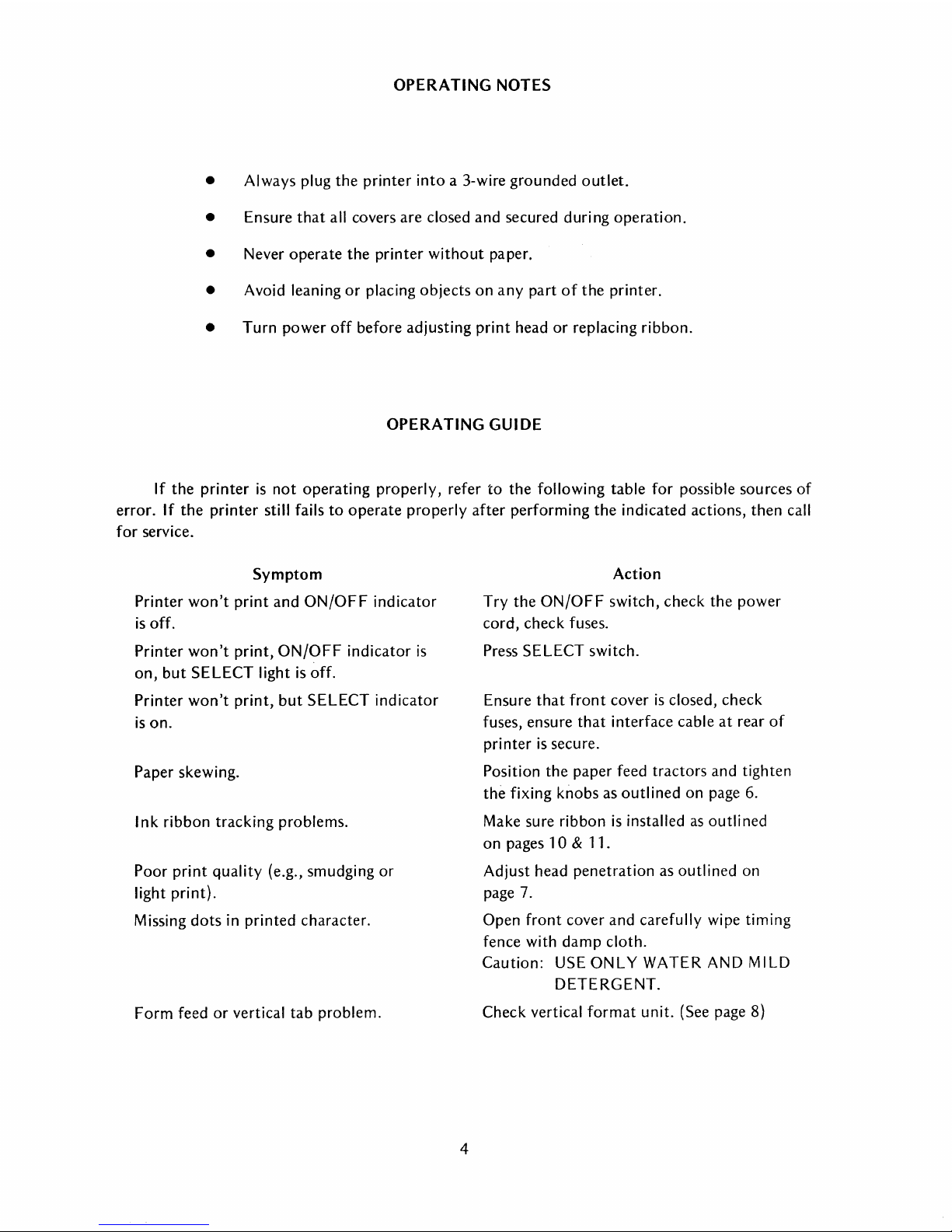
OPERATING NOTES
•
Always
plug
the
printer
into
a 3-wire
grounded
outlet.
•
Ensure
that
all covers
are
closed
and
secured
duri ng
operation.
• Never
operate
the
printer
without
paper.
• Avoid leaning
or
placing
objects
on
any
part
of
the
printer.
•
Turn
power
off
before
adjusting
print
head
or
replacing
ribbon.
OPERATING
GUIDE
If
the
printer
is
not
operating
properly,
refer
to
the
following
table
for
possible
sou
rces
of
error.
If
the
printer
still fails
to
operate
properly
after
performing
the
indicated
actions,
then
call
for
service.
Symptom
Printer
won't
print
and
ON/OFF
indicator
is
off.
Printer
won't
print,
ON/OFF
indicator
is
on,
but
SELECT
light is
off.
Printer
won't
print,
but
SELECT
indicator
is
on.
Paper
skewing.
Ink
ribbon
tracking
problems.
Poor
print
quality
(e.g.,
smudging
or
light
print).
Missing
dots
in
printed
character.
Form
feed
or
vertical
tab
problem.
4
Action
Try
the
ON/OFF
switch,
check
the
power
cord,
check
fuses.
Press
SELECT
switch.
Ensure
that
front
cover
is
closed,
check
fuses,
ensure
that
interface
cable
at
rear
of
printer
is
secure.
Position
the
paper
feed
tractors
and
tighten
the
fixing
knobs
as
outlined
on
page 6.
Make sure
ribbon
is
installed as
outlined
on
pages 1 0 &
11.
Adjust
head
penetration
as
outlined
on
page 7.
Open
front
cover
and
carefully
wipe
timing
fence
with
damp
cloth.
Caution:
USE
ONLY
WATER
AND MILD
DETERGENT.
Check
vertical
format
unit.
(See page 8)

OPERATOR CONTROLS AND
THIS SWITCH IS USED
TO
TURN
AC
POWER
ON
OR
OFF.
IT
LIGHTS
~::~~:::HR::~~::D
TO
SELECT
AFTER
IT
LIGHTS
PRINTER
THIS
FOR
PAPER
IT
PERFORMS
FUNCTION
FEED CODE.
THE
TURNING
WHEN
IS
SELECTED.
SWITCH
MANUALLY
IS
TO
TOP OF FORM.
THE
AS A
~
PRINTER
ON POWER. f
THE
USED.
SLEWING
FORM
_______
______
SAME ,
f
I . '
~
~
.•
t
~
..
..........
-------
••••
iii
SELECT
TOP
OF
FORM
:til
••••
INDICATORS
-
.---.. -...
/
,,!,t
111
~
,
PAPER
ou~~
•
THIS PUSHBUTTON SWITCH
(NOT
CONTAINED
101)
IS
USED
-- / Li NE FEEDS.
THE SAME
LINE
_______
~
FUNCTION
FEED CODE.
THIS
INDICATOR
PROVIDED
APPLICATIONS.
THIS
INDICATOR
TO
INDICATE
OF-PAPER
ON
FOR
MANUAL
IT
PERFORMS
FOR
AN
CONDITION
MODEL
AS A
IS
SPECIAL
IS USED
OUT-
THIS SWITCH WHEN
DEPRESSED
THE
INTERNAL
OUT
SWITCH,
THE
LAST
PRINTED
CHANGING
OVERRIDES
PAPER
ALLOWING
FORM
TO
BEFORE
PAPER.
BE
The printer also contains:
(1)
A
Bell
Alarm - consisting
BELL code (octal
007) or a paper empty condition.
of
a 2-second audible tone sounded
in
response to a
(2) A Form Thickness control knob (and lock knob) - located on the print head
of
carriage, adjusts the penetration
(3) A Platen Knob - used to manually adjust paper
by
pulling
It
out
and rotating it
the print wires on to the paper.
in
the printer. The knob ODerates
in
either direction.

LOADING
PAPER
1. Before
and
right
left
margin.
2.
Feed
follow
3. Place
of
the
top
of
When
4. Close
FIXING
KNOB
loading
pin
paper
the
down
the
forward
top
sheet
the
right pin feed
properly
the
gates
paper
into
feed
units. Make sure
through
paper
sheet
in
the
is
parallel
adjusted,
for
the
the
printer,
the
slanted
pan
and
come
paper
feed
with
the
top
unit
and
move
tighten
pin feed units,
the
first lift
the
left
opening
up
tractors.
of
the
the
fixing
then
the
pin feed
to
the
Make
printer.
unit
knob.
close
front
cover
and
unit
is
locked
in
the
top
of
pin feed
sure
to
the
tractors.
the
holes
If necessary, loosen
accommodate
forward
cover.
open
the
are
the
gates
in place
printer.
aligned so
the
the
width
for
at
the
The
that
fixing
of
the
left
extreme
paper
will
the
top
knob
on
the
paper.
PAPER
FEED
TRACTOR
PLATEN
KNOB
1. With
2. Use
the
form
hole in
tape
reader.
the
aligned vertically
platen
code
to
slew
printer
platen
knob
(octal
this
the
and
014)
same
turned
vertical
knob
to
with
the
rotating
is received
line
at
TOP OF FORM ADJUSTMENT
on,
press
the
TOP
OF
FORM
format
adjust
it in
the
print
or
top
paper
the
head.
either
the
of
the
tape,
paper
TOP
so
This
direction.
OF
next
directly
that
the
adjustment
Once
FORM
form.
6
Switch.
over
the
desired
is
performed
aligned,
Switch
This
light
top
each
is
pressed,
aligns
the
source
line
time a Form
in
the
on
the
by pulling
the
paper
top
paper
form
out
Feed
of
is
the
will

FORMS THICKNESS CONTROL
Two adjustment knobs on either side
between the
the thickness
platen and the face
of
the forms being used.
of
the print head. This clearance must be adjusted according to
On
of
the print head carriage control the clearance
a Series 102 printer, the two heads must be adjusted
independently.
To adjust the print head for optimum print quality perform the following steps:
1.
Loosen the Lock knob on the left side
2.
Increase the penetration
of
the print wires on to the ribbon
of
the print head.
Penetration Control knob.
3. Manually move the print head across the paper.
Keep
increasing the penetration until
smudging occurs.
4. Back off on the
5. Tighten the Lock knob to secure the print head
Penetration Control knob just to the point of
in
position.
Note
Numbers on
correspond
Penetration Control knob do not
to
the number
of
copies used.
by
slightly turning the
no
smudging.
LOCK
KNOB
7
----
PENETRATION
CONTROL
KNOB

VERTICAL
FORMAT
UNIT
Vertical
Format
Unit. This
The
tape
holes, located
the
defines
reader and
the
paper by
Vertical
paper
one
Reception
hole
in
Channel 5.
each Vertical
tab
Similarly,
switch advances
(BOF).
and
the
holes
66
sprocket
optional
standard
As an
of
form
form. BOF
On
sprocket
spaced
formatting
unit
is
a standard
between
in
is
located
Channels 3
Tab
(VT)
the
l-inch
format
Series
on
100
the
printers
upper
left side
wide, 8-channel, black
and
4,
have a
and
Channel 7
is
1/10
feed mechanisms are mechanically linked so
line
and
the
of
a Vertical
For
example,
will advance
reception
the
paper
feature
Detection
TOF
indications on
paper
apart
in Channel
holes
paper
Tab
the
of a Form
(and tape)
on
some
of
this
tape
apart
in
tape
code
(octal
if
the
holes
paper
six lines
Feed
to
the
next
printers, a hole
condition
tape
automatically
must
shipped with
5,
(corresponding
Channel 7
by
one
sprocket
013)
advances
in
Channel 5 are spaced six
(one
code
(octal
hole
in
be
separated
the
to a l-inch
(corresponding
controlled
of
the
opaque
inch
the
Top
hole,
inch).
014)
in
Channel
both
channels 5
advances
by
printer,
Vertical
to
by a paper
printer
pitch
between
of
Form
that
each line feed advances
on
the
paper
tape
just
under
paper
tape.
holes. Channel 5
(TOF)
format.
a 6 line-per-inch printer.
(and tape)
sprocket
or
pressing
the
TOP
7.
and
7 indicates
paper
to
the
at
least
one
line.
Tab
holes
tab)
and
Top
of
an
l1-inch
form).
in
the
the
The
holes
top
are
Form
to
OF
of
Vertical
left cover.
sprocket
The
tape
both
the
next
apart,
FORM
bottom
the
next
spaced six
holes
are
VERTiCAL
TAPE
READER
FORV,':'T
\ERTI(AL
TAPE
FORMAT
VERTICAL
DIRECTION
TAPE
SPROCKET
BETWEEN g
CHANNELS
~
SPACING
(1/10"
HOLES
~
3
&'I
I 0 0 o-r--
. g I
PITCH)
~l"WIDE~
USING
TELETVPEWRITER
GENERATE A TAPE
SPACING:
CH·~,II,J"~[~ -cO~-:qCi
CH.ANNH
CHANNEL
7'
5 & 7:
FORMAT
MOTION
TAPE
OF
•
g
g I TOP OF
~
TCHANNEL
g
o
o
o
o
o
o
o
o
CONTROL
"HIFT
P
ASCII
P
BOTTOM
CHANNELS
(OPTIONAL)
VERTICAL
CHANNEL50NLY
-0
SHIf- I & P
...
'~
OF
5 & 7
FORM
7
TAB
FORM
ONLY
8

VERTICAL
FORMAT
TAPE
1.
Generating
a Master
Tape
To
generate a master
tape
on a Teletypewriter
unit,
use
the
following
procedure:
a.
Turn
LOCAL
Switch
on
Teletypewriter
unit
to
extreme
clockwise
position.
b.
Turn
punch
switch
to
ON.
(Use black
opaque
tape
only.)
c. Press
HERE
IS
key
several
times
to
generate a tape
leader.
d.
To
generate
a Vertical
Tab
hole
in Channel 5, press
and
hold
the
CONTROL
key
and
then
press Q.
e.
To
generate a Top
of
Form
hole in Channel 7, press
the
SHIFT
and
P keys.
f.
To
generate a hole
in
both
Channels 5 and
7 (Vertical
Tab
and
Top
of
Form),
press
the
P key alone.
g.
To
space
the
tape
between
holes, press
and
hold
the
CONTROL
and
SHIFT
keys,
then
press P.
One
sprocket
hole will be
generated
each
time
the
P key
is
pressed.
h.
After
the
tape
has
been
fully
generated,
press
the
HERE
IS
key
to
generate
a rear
trailer
of
sprocket
holes.
Remove
the
tape
from
the
reader.
2.
Splicing
the
Tape
a. As
shown
in
the
figure, overlap
the
two
ends
of
the
tape
(A
and
B)
and
place
the
sprocket
holes
over
one
another
to
properly
align
the
two
ends.
Arrange
the
splice
so
that
the
distance
between
consecutive
Form
Feed holes
is
the
same
all
around
the
tape.
b.
Glue
both
ends
of
the
tape
together.
3.
Duplicating
the
Tape
SPROCKET
HOLE
VERTICAL
TAB
HOLES
a.
Insert
the
master
tape
in a Teletypewriter
reader
and
lock
it
in.
b.
Turn
the
switch
to
ST
ART
and a duplicate
tape
will be
punched
automatically.
9

RIBBON REPLACEMENT
(See diagram on opposite page)
To replace the ribbon, open the front cover and loosen the Lock knob on the left side
of
the
print head(s). Note setting on the
Penetration Control knob, then set knob to
No.5.
In
the
Model 102A, repeat this for both print heads. Open side covers. Remove caps from ribbon
reversing guides. Swing ribbon tension arms clear
of
spools. Lift spools from axles. Place empty
spool
(partially wound) on right-hand axle. Insert ribbon through right-hand reversing guide and
thread through idlers and ribbon guides.
Place full spool on left-hand axle, assuring
that
ribbon
is
inserted
in
left-hand ribbon reversing guide. Replace ribbon reversing guide caps. Close side
covers. Readjust
Penetration Controi knob to originai setting and iock.
in
Modei 102A, readjust
Penetration Control knob for both heads.
RIBBON SPECIFICATIONS
The printer uses a 1-inch nylon ribbon mounted on 3-inch diameter spools. The following
four colors are available:
Black
Red
Green
Blue
Part No. 63002293-01
Part
No. 63002293-02
Part
No. 63002293-03
Part
No.
63002293-04
PAPER SPECIFICATIONS
The printer uses continuous form paper with standard feed holes on each edge. Paper widths
from 4 to 14-7/8 inches can
be
accommodated by the printer.
Using
multiple-part form, one
original and up to 4 copies can
be
printed,
all
very legible. Paper weight specifications are
as
follows:
Single-Part
Forms:
Multiple-Part Forms:
Carbon
Paper:
15
to 20
Ib
Original - 12 to 15
Ib
Copies - 9 to 12
Ib,
last copy 15
Ib
(Maximum
of
five
parts)
7-1/4
Ib
with medium hardness
10

RIBBON
REPLACEMENT
DIAGRAMS
RIGHT-HAND~-
AXLE j
(A)
SERIES
~~
101
-~\
\
IDLER
PENETRATION
CONTROL
KNOB
(NOT
SHOWN)
-----~--rl
(8)
SERIES
11
102

SPECIAL CONTROL CODES
Reception
of
any
of
the following control codes from
printer action, as described below.
Octal
Function
BELL
LINE
FEED
VERTICAL
FORM FEED
CARRIAGE
TAB
Code
007
012
013
014
015
RETURN
ELONGATED
016
CHARACTER
Generates
ation, in
Advances
Advances
of
the
Advances
of
the
an audible
the
the
the
VFU
the
VFU
speaker
paper
paper
Causes the-line
buffer
matic
Prints
characters
to
be
printed.
line feed
entire
I ine
(double
Description
paper
paper
tape
paper
tape
of
characters
occurs
of
width).
the
input device will cause a special
tone,
at
one
until
until
As a
after
up
about
the
line.
the
is
reached.
the
is
reached.
standard
to
66
two
rear
of
next
hole
next
hole in Channel 7
stored in
printing
characters
seconds
the
printer.
in
the
feature,
the
line.
as
Channel 5
printer
an
expanded
in
dur-
auto-
SELECT
DE-SELECT
DELETE
021
023
I I
1
"
Note:
Selects
data).
De-selects
Because
logic
acters
in
the
must
of
order: (1) first
33
"Don't
printable
code.
first 66
the
printer
Not
available
the
characters, and
The
characters
(Le., makes
printer
the
two
102A, a line
be received in
33
printable
care"
characters, (3)
102AL,
double
on
Model 101.
(Le.}
prevents
receiv'ng data}. Not available
Clears the
12
buffer
and
initializes the
print
heads
of
elongated
the
(4)
however,
width.
it
available
the
on
Modell
printer
and
internal
char-
following
characters, (2)
next
33
carriage
prints
printer
to
return
the
receive
from
01.
electronk~.

STANDARD
CHARACTER
SETS
STANDARD
5 X 7
CHARACTER
MATRIX
040
041
042
043 044
04e
04e 047
II1IIIII
050
oel
oe2
<le3
oe4
oee
oes
oe7
111111111
060
061
062
OS3 OS4
ose
otiS
otI7
IIIIIIII
070
071
072
073
074
Onl
078
077
IIIIIIII
100
101
102
103
104
lOti
loti
107
IIIIIIII
110
III
112 113 114 115 116
117
IIIIIIII
120
121
122
123
124
12e 12S
127
lmltm:tttmttmmtlffi11lfRlffi11
EElBIBmtHDIM1
130
131
132 133
134
13e
1311
137
II1IIIII
STANDARD
9 X 7
CHARACTER
MATRIX
040
041
042
043
045
04S
047
II1IIIII
050
051
oe2
053
054
oee
OtiS
057
111111111
060
061
062
OS3 OS4
OS5
otiS
OS7
IIIIIIII
070
071
072
073
074
Onl
0711
077
IIIIIIII
100
101
102
103
104
103
lOS 107
IIIIIIII
110
III
112 113 114 115
116
117
IIIIIIII
120
121
122
123
124
12e 12S
127
;m,tm:.lmltm.fmf~tf:Rlmil
EEE.me.E
130
131
132
133 134 135 13S 137
III1IIII
00 00
0
1
o 1
1
0
1 0 1 1
1 1
~
~
b
6
~
0
1
0
1 0 1
0
1
B.
b
~
It
~b4b3b2
bl~
t t t
tRow
USASCII CODE
ized
Notes:
1.
~
Indicates
control codesrecogn
by
Centronics printe
rs
7)
2.
Underscore (octal 13
is
replaced by a back
arrow in the standar
-
d
9 x 7
matrix
0 0
o 0
0
o 0
o 1 1
o 0 1 0
2
o 0 1
1
3
o 1
o 0
4
0 1
o 1
5
0
1 1 0
6
0
1
1 1
7
1
0
0 0
8
1
0
o 1
9
1
0 1 0
10
1
o 1
1
11
1
1 0 0
12
1 1
0
1
13
1
1 1
0
14
1
1 1
1
15
0 1
2 3
4 5
6
7
NUL
DLE
SP
0
@
P
\
P
SOH
DCl
!
1
A
0
a
q
STX
DC2
"
2
B R b
r
ETX
DC3
#
3
C
S
c s
EOT
DC4
$
4
D
T d
t
ENO
NAK
%
5
E
U
e
u
ACK
SYN &
6
F
V
f v
~EL
ETB
,
7
G
W g
w
BS
CAN
(
8
H
X
h x
HT
EM
)
9
I
Y
i
y
'''LF
SUB
*
J
z
j
z
ryT
ESC
+
I
K
[
k
{
"'FF
FS
,
<
L
"-
I
I
"'CR
GS
-
-
M ]
m
}
"'SO
RS
>
N
"
n
"'""
SI
US
/ ?
0
a
DEL
-
....
' -
.....
--_"'-----"'''----v----''
CONTROL
STANDARD
OPTIONAL
CODES
 Loading...