

Centron MS-930-970 Service manual

SERVICE MANUAL
SEGMENTATION SYSTEM
Model
MS930A, MS930E
MS940A, MS940E
MS950A, MS950E
MS960A, MS960E
MS970A, MS970E
Centron Technologies Corporation

SERVICE MANUAL
SEGMENTATION SYSTEM
Model
MS930A, MS930E
MS940A, MS940E
MS950A, MS950E
MS960A, MS960E
MS970A, MS970E
No. CAT.MS950SM1.1Ee
ISSUE 2
Centron Technologies Corporation
319-25 Sadang-4-dong, Dongjak-ku
Seoul 156-823 KOREA
Tel.
Fax. +82-2-522-7806
Website: www.centrons.com
+82-2-522-7807
DEC. 2005

Do not open the covers. Risk of electric shock exists.
Do not operate this machine in close proximity to any person
with a pacemaker or to any sensitive electronic apparatus.
The recommended minimum safety distance is 12 feet (3.6 m).
1. Safety notices:
Important Notes
* WARNING *
Warranty may be voided if the covers are opened.
* WARNING *
This machine generates high-level power of 40.68 MHz radio-frequency (RF).
Users are requested to be cautious of potential electric shock or hazard.
• Do not operate the machine without the protectors on the sealing heads.
• Do not insert fingers into a sealing head.
• Always turn the power switch off before cleaning the machine.
• Only authorized and trained personnel should remove covers.
2. Installation:
Nominal AC mains voltage of the models MS930A-970A is 100-120 volts 50/60Hz,
and operational voltage range is 90-132 volts.
Nominal AC mains voltage of the models MS930E-970E is 200-240 volts 50/60Hz,
and operational voltage range is 180-264 volts.
3. Cleaning:
(1) Always keep the sealing head area clean and dry. If the sealing heads become
wet or dirty, arcs may appear during sealing. If an arc appears, clean the sealing
heads and let them dry thoroughly.
(2) Use a soft cloth and mild detergent to clean the machine. After cleaning, wait a
few minutes until the area cleaned is completely dried. Do not use paint thinner,
benzene, solvent or any strong detergent.
(3) Avoid using or leaving the machine in a location where temperature is higher than
50 °C (122 °F). Keep it away from any heating source or direct sunlight.
i

Contents
Important Note i
Contents ii
List of Figures iii
1. Introduction 1-1
1-1. General 1-1
1-2. Feature 1-3
1-3. Specification 1-4
2. Appearance and Function 2-1
2-1. Control Unit 2-1
2-2. Segmentation Unit 2-4
3. System Description 3-1
3-1. General 3-1
3-2. Control Board 3-3
3-3. I/O Board 3-3
3-4. Power Distribution Board 3-3
3-5. Power Supply Unit 3-3
3-6. Filter Board 3-3
3-7. RF Board 3-4
3-8. Distribution Board 3-5
3-9. Sealing Head Unit 3-5
3-10. Switch Board 3-6
3-11. Trigger Board 3-6
3-12. Matching Board 3-6
4. Standard Operating Procedure 4-1
4-1. Operation Mode 4-1
4-2. Operation in Local Mode 4-4
4-3. Operation in Remote Switch Mode 4-4
4-4. Operation in Remote Circuit Mode 4-4
4-5. Operation in Remote Command Mode 4-4
5. Maintenance and Troubleshooting 5-1
5-1. Precaution 5-1
5-2. Test Equipment 5-2
5-3. Troubleshooting Procedure 5-3
5-4. Adjustment of Variables 5-7
5-5. Fixtures for Remote Mode Control 5-9
5-6. Adjustment of RF 5-11
5-7. Cleaning Sealing Head 5-13
ii
page

6. Schematic Diagram 6-1
7. Technical Illustration 7-1
8. Parts List 8-1
List of Figures
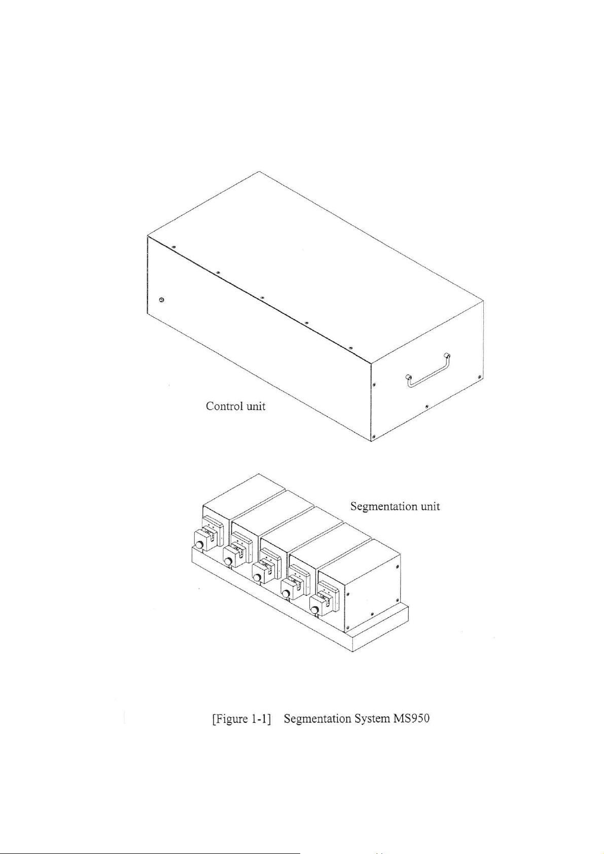
[Figure 1-1] Segmentation system MS950 1-2
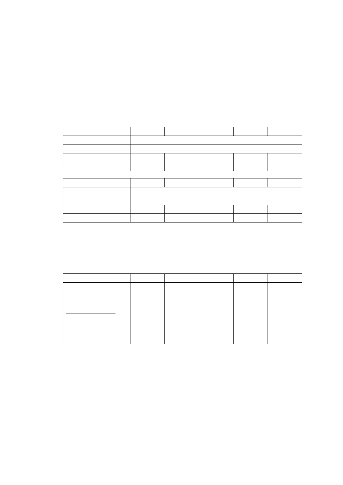
[Figure 2-1] Control unit 2-1
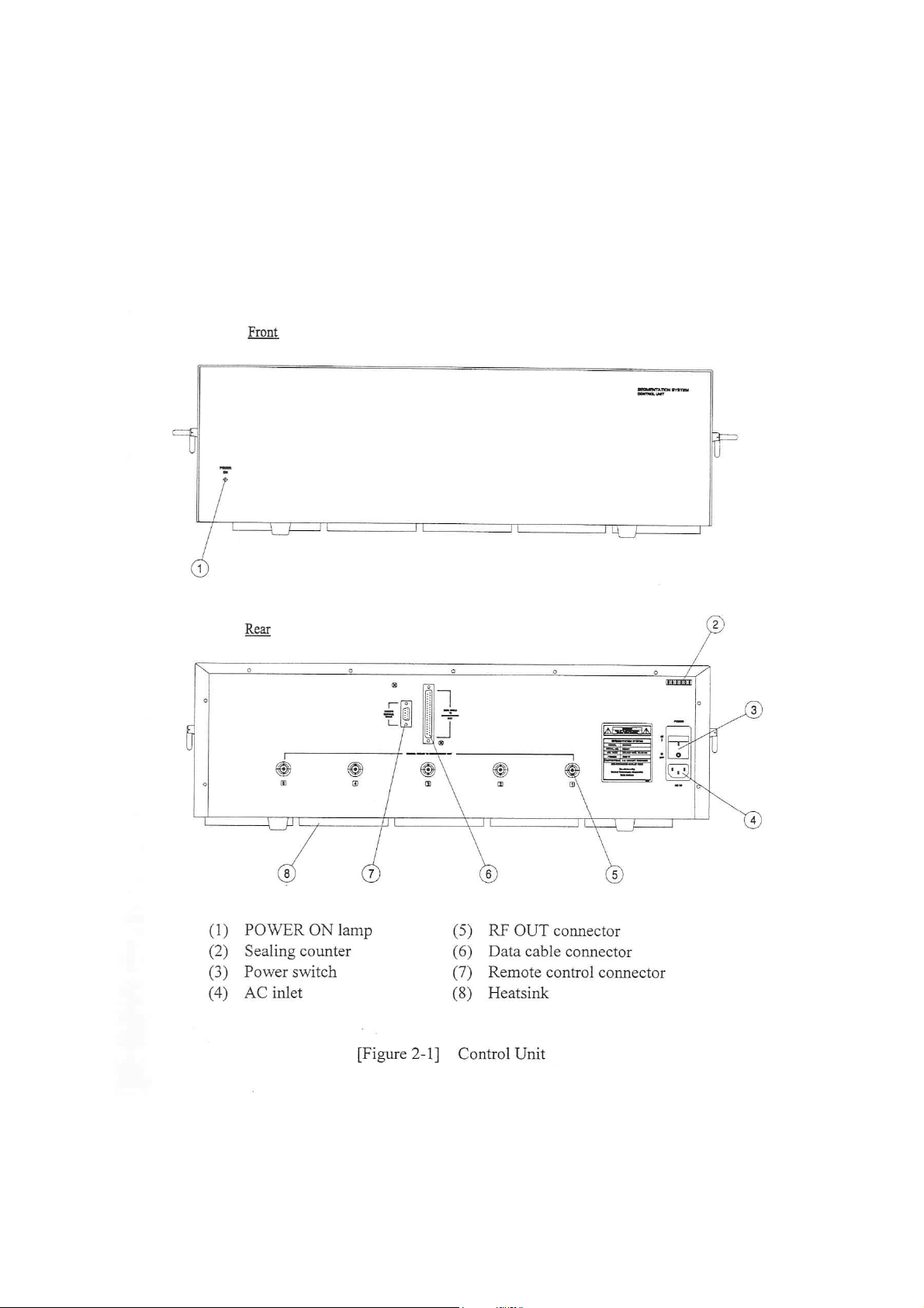
[Figure 2-2] Segmentation unit 2-4
[Figure 3-1] Overall system block diagram 3-2
[Figure 3-2] RF board functional block diagram 3-4
[Figure 3-3] Sealing head unit functional block diagram 3-5
[Figure 5-1] Troubleshooting flow chart 5-4
[Figure 5-2] Remote control scheme 5-9
[Figure 5-3] RF test set-up 5-11
[Figure 6-1] System wiring diagram 6-2
[Figure 7-1] Exploded view of MS950 Control unit 7-2
[Figure 7-1] Exploded view of MS950 Segmentation unit 7-3
[Figure 7-2] Control board layout 7-4
[Figure 7-3] I/O board layout 7-5
[Figure 7-4] RF board layout 7-6
[Figure 7-5] Power distribution board layout 7-7
[Figure 7-6] Distribution board layout 7-8
[Figure 7-7] Trigger board layout 7-9
[Figure 7-8] Matching board layout 7-9
[Figure 7-9] Switch board layout 7-9
[Figure 7-10] Filter board layout 7-9
iii
page

1. Introduction
1-1. General
This Service Manual covers all technical information of Segmentation Systems
MS930A/E - MS970A/E for servicing and maintenance of the machines.
The model numbers of Segmentation System denote the number of sealing head, and
the voltage range of AC main.
Model number Number of sealing head AC mains voltage
MS930A 3 100-120 VAC
MS930E 3 200-240 VAC
MS940A 4 100-120 VAC
MS940E 4 200-240 VAC
MS950A 5 100-120 VAC
MS950E 5 200-240 VAC
MS960A 6 100-120 VAC
MS960E 6 200-240 VAC
MS970A
MS970E
7
7
100-120 VAC
200-240 VAC
This manual contains ;
1. Introduction
2. Appearance and Function
3. System Description
4. Standard Operating Procedure
5. Troubleshooting and Adjustment
6. Schematic Diagram
7. Technical Illustration
8. Parts List
The Segmentation Systems are precision electronic equipment. Troubleshooting and
repair must be carried by authorized service personnel.
1 - 1
1 - 2

1-2. Feature
The Segmentation System is a device to make multiple number of seals or segments
of thermoplastic tubing in a few seconds. The machine generates high-level power of
40.68 MHz radio-frequency signal for a melting process called 'dielectric heating'.
Tubing in the sealing heads melts quickly in about two to three seconds, and then
cools to form seals.
The Segmentation System consists of a control unit, a segmentation unit and an
inter-unit cable assembly. The segmentation unit can be installed up to 1.5 meters
away from the control unit.
The system operates in one of four operation modes - local, remote switch, remote
circuit and remote command modes. The system works in local mode if no connector
is connected to the remote control connector on the rear panel of control unit.
Either remote switch mode or remote circuit mode is selected when a specially-made
remote control connector is put on the 9-pin D-sub connector on the rear panel of
control unit. Remote command mode is selected by software commands from an
external computer circuit or a personal computer connected to the 9-pin D-sub
connector on the rear panel of control unit with RS-232C serial communication.
The system has versatile features as the followings:
- The machine can be operated stand-alone, or be controlled by a circuit or a PC.
- The control unit can be placed under the table. It saves bench space.
- Distance between sealing heads is adjustable to one of 75-80-85-90 mm.
- Each sealing head can be enabled or disabled individually by switches or by PC.
- Time interval of sealing head starts is selectable between 60-160 milliseconds.
- Operation sequence of sealing heads is selectable - right to left or left to right.
- Timing of sealing head returns is selectable - simultaneously or individually.
- Thickness of seals can be adjusted.
- Indication lamp blinks and buzzer beeps in case of improper operation.
- The event counter on rear panel counts number of sealing cycles done.
1 - 3
1-3. Specification
(1) System configuration : control unit, segmentation unit, inter-unit cable
(2) Operation modes : local, remote switch, remote circuit, remote command
(3) Operation frequency : 40.68 MHz
(4) Overall sealing time : 1 - 3 seconds
(5) Available tubing size : 2 - 6 millimeters in diameter
(6) AC mains voltage
Model MS930A MS940A MS950A MS960A MS970A
Nominal voltage 100-120 VAC, 50/60 Hz, single phase
Working voltage 90-132 VAC, 47-63 Hz, single phase
Power consumption 600 W 800 W 1000 W 1200 W 1400 W
Current rating 6 A 8 A 10 A 12 A 14 A
Model MS930E MS940E MS950E MS960E MS970E
Nominal voltage 200-240 VAC, 50/60 Hz, single phase
Working voltage 180-262 VAC, 47-63 Hz, single phase
Power consumption 600 W 800 W 1000 W 1200 W 1400 W
Current rating 3 A 4 A 5 A 6 A 7 A
(7) Over-current protection : By recoverable circuit breaker
(8) Indication lamps
- Control unit : POWER ON (green)
- Segmentation unit : READY (green), SEALING (red)
(9) Alarms : audible indication by buzzer, visual indication by lamps
(10) Dimension and weight
Model MS930A/E MS940A/E MS950A/E MS960A/E MS970A/E
Control unit
- Size, W-H-D [mm]
- Weight [Kg]
Segmentation unit
- Number of head
- Size, W-H-D [mm]
- Weight [Kg]
- Set distance [mm]
406-200-310
9.5
3
255-155-210
7.5
75,80,85,90
518-200-310
10.5
4
345-155-210
9.0
75,80,85,90
630-200-310
11.5
5
435-155-210
10.5
75,80,85,90
742-200-310
12.5
6
525-155-210
12.0
75,80,85,90
854-200-310
615-155-210
75,80,85,90
(11) Inter-unit cable
- RF Cable : RG-58, 1.8 meters (6 feet) long, BNC-male at both ends
- Data Cable : 1.8 meters long, 37-pin D-Sub connectors at both ends
(12) Communication parameters
- Baud rate: 19200 bps - Data bits: 8 - Stop bits: 1
- Parity: None - Flow control: None
(13) Temperature characteristics
- Operating : 0 ° ~ 40 °C ( 32 ° ~ 104 °F)
- Storage : - 20 ° ~ 70 °C ( - 4 ° ~ 158 °F)
13.5
7
13.5
1 - 4
2. Appearance and Function
2-1. Control Unit
(MS950A/E shown)
2 - 1

The control unit contains power supplies, RF generator boards and control circuit board.
Each power supply unit supplies 12 volts DC current to each RF generator board that
generates 40.68 MHz RF power. RF powers go to the segmentation unit through coaxial
cables in the inter-unit cable assembly.
The power switch
(1)
lamp
lights. The power switch module contains a recoverable circuit breaker that trips
(3)
is located on the rear panel. When it is turned on, the POWER ON
off when an over-current condition occurs in the system. There is no other control on the
control unit.
Connections with the segmentation unit are made from rear panel. An end of each cable in
(5)
inter-unit cable assembly is plugged at RF OUT connectors
Remote control connector
(7)
is used only when the machine is operating in remote mode.
and data cable connector
A cycle of sealing process starts by a signal from the segmentation unit given through the
inter-unit cable, or by a signal from a remote control device connected at the remote
control connector. The control unit feeds RF powers to all sealing head units for a
determined period of time, as well as it controls movement of each sealing head.
The sealing counter
(2)
counts up by 1 at each one cycle of sealing process.
Upon receiving start signal, the sealing heads start not at same time but one by one in
series. Time interval between start of one sealing head and start of the next sealing head
can be selected between 60-160 milliseconds with 20 milliseconds step.
Operation sequence of sealing heads can be also selected, to start them from the right head
to the left head, or from the left head to the right head.
Return timing of sealing heads can be selected too. Each sealing head can be returned
individually at the moment when sealing ends at that sealing head unit, or all sealing
heads can be returned simultaneously when the last working sealing head ends its job.
Each sealing head can be enabled or disabled individually by switches on the control
circuit board, as well as by software command if the machine works in remote mode.
Default factory settings and adjustment procedures are found in Section 5-2.
The machine operates in one of four operation modes: local, remote switch, remote circuit
and remote command modes. Power-on default is local mode if no connector is connected
on the remote control connector. Details are found in Section 4.
When sealing is not made at a sealing head, audible and visual alarms are activated. Alarm
condition is set up when any sealing head has not made seal in 3 seconds from start due to
circuit failure. Alarm continues until the trigger lever at #1 sealing head is released by
removing tubing.
(6)
.
2 - 2

In alarm condition, the followings take place:
(1) The green POWER ON lamp on the front panel of control unit flashes.
(2) Beeps sound.
(3) Only in remote command mode operation, a status code among $A,2½ - $E,2½ is
displayed. For example, when # 3 head does not work, $C,2½ will be given.
Not having alarms does not mean that all seals made are perfect. Alarm feature is
provided not to decide automatically that all seals have been made perfect or incomplete,
but to detect circuit failure to make the machine stop before starting the next cycle of
sealing operation.
2 - 3
2-2. Segmentation Unit
(MS950A/E shown)
2 - 4

The segmentation unit has all sealing head units
base plate
(1)
. All sealing head units are identical in configuration, but only the trigger
(2)
and a signal distribution board in the
lever in the sealing head unit mounted at #1 position is active and another trigger levers
are in inactive state.
The trigger lever in #1 sealing head unit has two features. In local mode of operation, a
cycle of sealing starts when it is depressed. In any one of three remote modes, it senses
presence of tubing in #1 sealing head unit, then makes control circuit be ready to accept a
remote start command to be given by a remote start switch, a remote start circuit or a
remote control computer only when it detects tubing has been loaded in the #1 sealing
head.
Mounting distances between sealing head units are adjustable at 75, 80, 85 or 90 mm.
Users can adjust the distances as necessary.
An ENABLE/DISABLE selector switch is prepared on the rear panel of each sealing head
unit. If the selector switch is selected at DISABLE, the sealing head unit does not work
even if an ENABLE command is given in remote command mode.
On each sealing head units are two LED indication lamps. The green READY lamp
turned on when the ENABLE/DISABLE selector is set at ENABLE position. The red
SEALING lamp
(5)
is turned on only while sealing is being done. Both lamps will be off if
the ENABLE/DISABLE selector switch is set at DISABLE position.
The head protectors
(4)
should be placed securely all the time with protector screws
(3)
Risk of electric shocks at the sealing head may exist if the protector is removed.
Behind the head protector are sealing head section and the trigger lever. Pressing the
trigger lever initiates a cycle of sealing process. The moving part of sealing head comes
out to squeeze tubing, and then RF power is applied. Tubing melts in second. After tubing
melted and hardened again, the moving head retreats automatically.
(6)
is
.
2 - 5

3. System Description
3-1. General
The Segmentation System consists of the control unit, the segmentation unit and an
inter-unit cable assembly.
The control unit contains one control circuit board and 3 - 7 pieces of power supply and
RF board, depending on the model. E.g., MS950A/E has 5 power supplies and RF
boards. The segmentation unit has same number of sealing head unit and a signal
distribution board in the base plate. All sealing head units are identical in configuration,
but only the trigger lever in the sealing head unit mounted at #1 position works.
The inter-unit cable assembly is a bundle of data cable and RF coaxial cables.
Refer to [Figure 3-1] to find overall system configuration.
The control board in control unit contains all logic circuits and timing gates. It
receives trigger command signal from #1 sealing-head unit, and controls overall
function of this equipment. RF board assemblies locate in control unit, which are highpower RF oscillator-amplifiers generating RF power, and sends RF power to all
sealing-head units through inter-unit cable assembly.
Each sealing-head unit consists of a solenoid, sealing electrode, matching board
assembly, trigger board assembly, micro-switches and a ENABLE/DISABLE switch.
The ENABLE/DISABLE selector switch is prepared on the rear panel of each sealing
head unit. If the selector switch is selected at DISABLE, the sealing head unit does not
work even if an ENABLE command is given in remote command mode. Matching
board assembly has an impedance transformer. Trigger board assembly has a trigger
micro-switch and two indication lamps.
Following paragraphs describe theory and function of each assembly in detail.
3 - 1
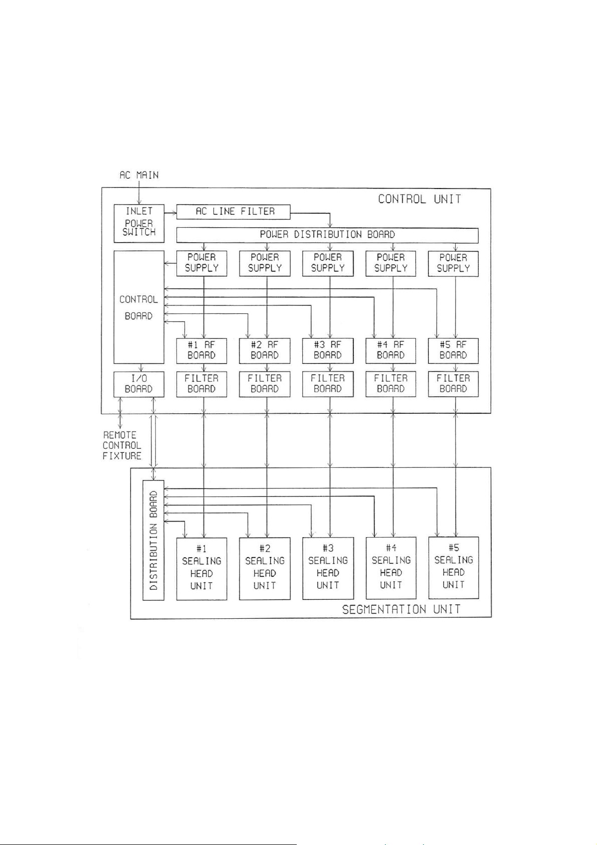
[Figure 3-1] Overall System Block Diagram
3 - 2

3-2. Control Board
Control board is a microprocessor-based circuit and has eight identical channels of
control circuitry. The board is powered by #1 power supply unit.
Sealing operation starts by a trigger signal, either come from the trigger switch in #1
sealing head unit or given by command at a remote control mode. The microprocessor
generates all timings to turn each RF board on and off, and to make each solenoid
work. Working timing and sequence of each sealing head unit are adjustable at
switches SW1 and SW2 on the control board.
3-3. I/O Board
I/O board has EMI filters on each signal lines and two opto-couplers for isolation of
remote control fixtures.
3-4. Power Distribution Board
This board distributes AC mains to eight identical channels.
It has a buzzer on the board.
3-5. Power Supply Unit
Power supply units are switching-mode power supplies. Each unit takes either 200-240
VAC or 100-120 VAC as input, and provides regulated voltage of 12 VDC as output.
The power supply units in an A-suffix model take 100-120 VAC only, and the ones in
an E-suffix model take 200-240 VAC only.
3-6. Filter Board
Filter board has RF filters to decrease high-order harmonic frequency components.
3 - 3
 Loading...