

Centrometal PelTec-lambda 24, PelTec-lambda 12, PelTec 36, PelTec-lambda 36, PelTec 48 Technical Instructions
...Page 1
PelTec 12-48
PelTec-lambda 12-48
TECHNICAL INSTRUCTIONS
for installation, use and maintenance
of hot water boiler
and installation of additional equipment
THE FIRST START-UP MUST BE DONE B Y AUTHORIZED PERSON
OTHERWISE PRODUCT WARRANTY IS N O T VA LID
HEATING TECHNIQUE
Centrometal d.o.o. - Glavna 12, 40306 Macinec, Hrvatska, tel: +385 40 372 600, fax: +385 40 372 61 1
Page 2
2
Technical instructions PelTec-lambda
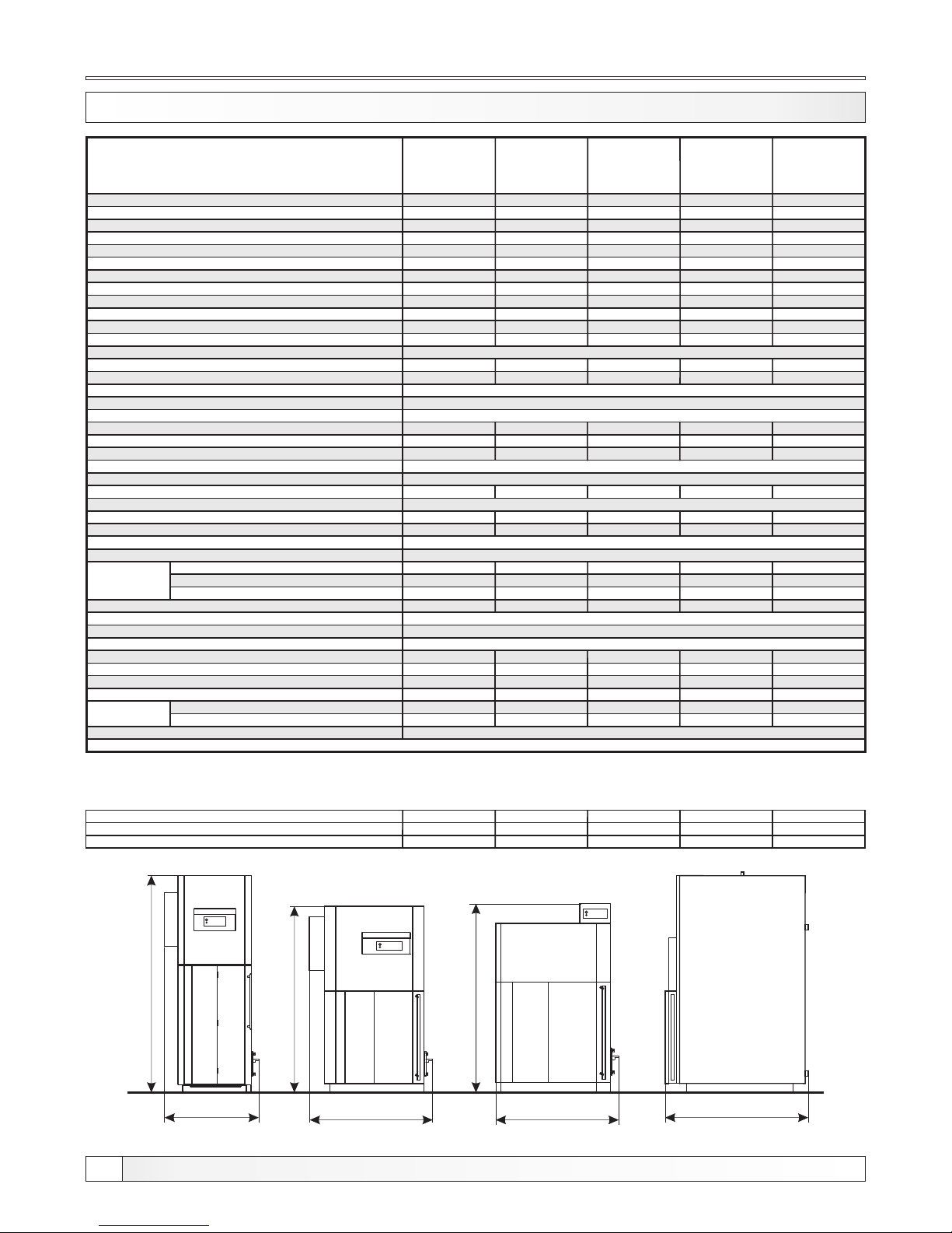
Technical data
TECHNICAL INFORMATION
Dimensions of the boiler to enter the room
Width (G)
Depth (H)
Height (I)
650
765
1565
880
765
1275
880
735
1345
965
795
1345
965
795
1495
** possible way of installing the fan (output is directed up) *** possible way of installing the fan (output is directed sideways)
HG
I
G
I
G
I
12 kW 18 kW
24 kW
48 kW36 kW
12 kW 24-48 kW18 kW 12-48 kW
Tip
(A)
(B)
(C)
(kW)
(kW)
(mbar)
(lit.)
(°C)
(°C)
(kg/s)
(kg/s)
(h)
(°C)
(°C)
(°C)
(W)
(mbar)
(%)
(mm)
(lit.)
(mm)
(lit.)
(lit.)
(lit.)
(W)
(W)
(V~)
(Hz)
(mm)
(mm)
(mm)
(kg)
(bar)
(bar)
(°C)
(mm)
(mm)
(mm)
(mm)
(R)
(R)
12
3,6-1 2
5
0,05
78
120
100
0,013 1
0,000 5
-
-
65-90
5
0,942
465x3 00x300
41,85
9,9 / -
1050
1105
1200
1560
328
130
1515 / 12 35
135
555
1"
1/2"
18
5,4-1 8
5
0,05
76
120
100
0,016 4
0,002 9
-
-
65-90
9
1,59
650x3 00x300
58,5
6,5 / 9,9
1050
1105
1420
1560
349
130
1040 / 76 5
125
510
1"
1/2"
24
7,2-2 4
5
0,05
100
120
100
0,019 7
0,005 2
-
-
65-90
> 0°C
13
C1, woo d pellets
maxim um 12 %
Ø6 x 50
1.59
650x3 00x300
58.5
under pressur e
340
9,9 / 9.9
by EN 303 -5, point 4 .2.5
1050
220
50
1080
1400
1560
402
2.5
5
90
130
1140 / 8 55
130
495
5/4"
1/2"
with fa n
under n on-cond ensing conditi ons
36
10,8- 36
5
0,05
108
120
100
0,031
0,009 2
-
-
65-90
10
2,56
620x3 85x385
91,90
11,6 / 1 7,7
1100
1160
1485
1560
455
150
1160 / 8 55
120
555
5/4"
1/2"
48
14,4- 48
5
0,05
135
120
100
0,041
0,013 1
-
-
65-90
14
2,56
770x3 85x385
114, 13
13 / 19,6
1100
1175
1485
1560
478
150
1310 / 99 5
115
555
5/4"
1/2"
PelTec /
PelTec-lambda
12
PeTec /
PelTec-lambda
18
PelTec /
PelTec-lambda
24
PelTec /
PelTec-lambda
36
PelTec /
PelTec-lambda
48
Nominal heat output
Heat output range
Boiler class
Required chimney underpressure
Water amount in boiler
Exhaust gas temperature at nominal heat output
Exhaust gas temperature at minimal heat output
Exhaust mass flow at nominal heat output
Exhaust mass flow at minimal heat output
Combustion period
Min. inlet water tem. at the boiler supply water connection
Setting range for temperature controller
Minimal return temp.at boiler return tapping
Standby heat losses
Boiler resistance on water side at nominal output
Fuel type
Fuel moisture content
Fuel size
Firebox volume
Combustion chamber dimensions
Combustion chamber volume
Combustion chamber type
Pellet tank volume
Volume of ash boxes (left / right)
Required minimum accumulation next to boiler
Auxiliray power requirements at Q
N
Auxiliray power requirements at Q
min
Supply voltage
Frequency
Total mass - (boiler with tank and feeder screw)
Max. operating overpressure
Test pressure
Max. operating temperature
Flue gas tube - external diameter
Dimension D**/D***
Dimension E
Dimension F
Heating appliance running
Heating appliance running
Boiler body
dimensions
Lengh t
Width
Heigh t
Boiler
connections
Flow and return pipe (male thread)
Charge/discharge (female thread)
Page 3
3
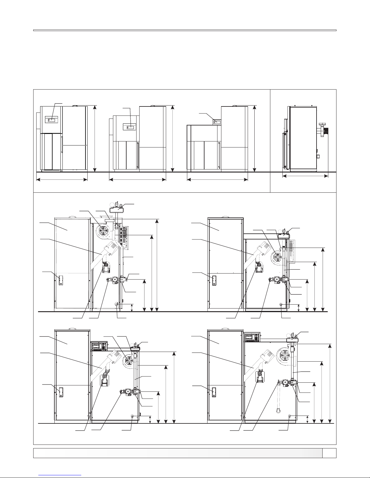
Dimensions and basic parts of the boiler
PLV - Boiler flow
PVV - Boiler return
PP - Charge / Discharge
DP - Flue gas tube
VE - Fan (fan output can be mounted in any directions)
SP - Pellet tank
PT - Pellet feeder
RP - Pellet level sensor
SG* - Safety ventilation group (not included in delivery)
PG - Pump group
PE - Connection for expansion vessel
FC - Flexible PVC tube
* not included in delivery
** possible way of installing the fan (output is directed up) *** possible way of installing the fan (output is directed sideways)
A
B
C
B
12kW
B
C
RE
RE
C
RE
Front view
Side view
12-48kW
Back view
PVV
PP
PelTec /
Peltec-lambda
12
SG *
PT
RP
FC
PVV
PE
PLV
PG
SP
VE DP
E
F
D***
D**
PT
SP
RP
SG *
E
F
D***
D**
FC
PE
PP
DP
VE
PG
PLV
SG *
RP
PT
SP
FC
PE
PP
DP
VE
F
D***
D**
E
PVV
PLV
PG
SG *
PT
SP
RP
FC
PE
PP
F
D***
D**
E
PVV
PLV
PG
PelTec /
Peltec-lambda
18
PelTec /
Peltec-lambda
24-36
PelTec /
Peltec-lambda
48
18kW 24-48kW
Technical instructions PelTec / PelTec-lambda
Page 4
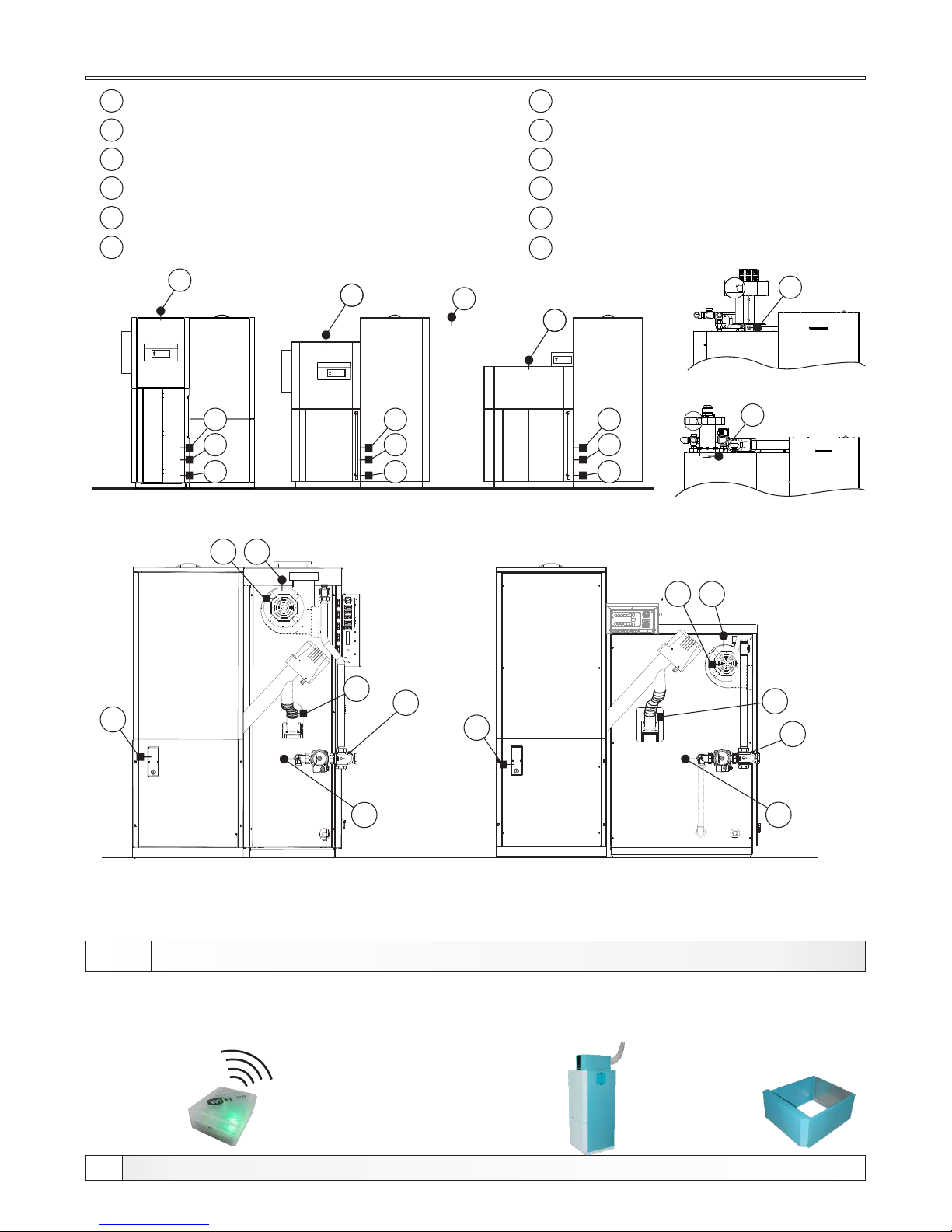
Basic parts and sensors
4
Technical instructions PelTec / PelTec-lambda
1 - Boiler sensor ( 5k)NTC
2 - sensor ( 5k)
1
DHW NTC
3 - Presostat
4 - Photocell
5 - Electric heater
6 - Flue gas sensor (Pt 1000)
7 - Fan speed sensor
8 - tube bimetal sensorPVC
9 - Pellet level in the tank
1
10 - Flow sensor ( 5k)NTC
11 - Return sensor ( 5k)NTC
12 - Lambda probe
ADDITIONAL EQUIPM ENT
Depending on the configuration can be used as: DHW sensor, flow temperature sensor,
accumulation tank sensor (CAS), hydraulic crossover (CRO)
Only PelTec-lambda
*
**
11
4
3
5
12
PelTec-lambda 18-48 kW
12
PelTec-lambda 12 kW
24-48 kW
9
7
6
8
10
11
18-48kW
9
8
10
6
7
11
11
1
2
4
3
5
4
3
5
12 kW 18 kW
*
*
*
**
**
12 kW
*
**
CAL - alarm
box
(speaker/
LED)
CM2K modul
for regulation
2 heating
circuits
CMNET modul
for boiler
cascade
GSM Alarm
modul
for mobile
network
Pelet
suction
system
Cm wifi-box
(Internet
supervision)
Increasing
volume
of pellet tank
(+77kg, h=300mm)
Page 5
1.0. INTRODUCTION
The PelTec / PelTec-lambda has a modern construction and design and is made out of the controlled
materials of high quality, welded with most modern technology and is approved and tested under EN
303 - 5 norm and fulfil all special request for the connection on the installation of a central heating
system.
1.1. BOILER DESCRIPTION
All local regulations, including those referring to national and European standards need to be
complied with when installing the appliance.
The boiler must not be modified unless using the tested original accessories we provide or if the
work is undertaken by our Customer Service.
Only fit original spare parts. These can be obtained from your customer service partner or directly
from ourselves. European standards need to be complied with when installing the appliance.
Regular care and cleaning of the appliance, flue gas outlets, connecting piece and flue.
CAUTION:
The flue may block if the boiler is heated again after a long period of it not being used. Before
starting the boiler, have the flue checked by a specialist (chimney sweep).
Ensure sufficient supply of fresh air in the installation room when heating. The air must be replaced
at least 0.8 times an hour through constant and reliable room venting. Fresh air may have to be
provided from outside if the windows and doors in the room where the boiler is installed are well
sealed or if this room contains other equipment, such as extractor hoods, clothes dryer, fan etc.
1.2. SAFETY PRECAUTIONS
1.3. IMPORTANT INFORMATIONS
This symbol indicates measures for protection against
accidents and warning for the user and / or exposed
persons.
Steel hot water boiler are engineered for wood pellet firing. In the boiler is installed the burner for wood
pellet firing with the automatic firing and automatic self-cleaning function which enables the reliable
operation also with the low quality wood pellets. The function of the automatic cleaning flue gas tubes
provides the unifying exchange of the heat and high and unifying level of boiler efficiency. Digital boiler
controller in a basic construction offers also the possibility of control with the additional equipment likes
lambda probe or level control of the wood pellets in the pellet tank. The pellet tank is the integral part of
the boiler. The boiler is delivered in pieces due to the easier transport into the boiler room.
The boiler and related accessories are state of the art and meet all applicable safety regulations.
The control unit, wiring chamber, el. heater, safety cut-out STB thermostat, fan, grid cleaning
mechanism, flue gas tubes cleaning mechanism and pellet supply mechanism are integrated into the
PelTec / PelTec-lambda . They are operate at a voltage of 230 V AC. Improper installation or repair can
pose the danger of life-threatening electric shock. Installation may beperformed only by appropriately
qualified technicians.
Caution symbols:
Please take careful note of the following symbols in this Operating Manual.
Introduction, boiler description, safety precautions, important informations
5
Technical instructions PelTec / PelTec-lambda
Page 6
1.4. STATUS OF D ELIVERY
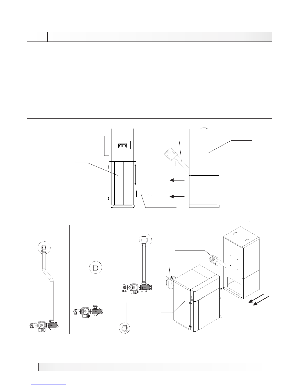
Equipment is delivered seperately:
1. Boiler with planking and thermal insulation
2. Pellet tank in a cardboard box (the parts need to be mounted, see instructions for mounting
the pellet tank)
3. Feeder screw with a flexible PVC tube (should be placed in the pellet tank)
4. Grating cleaning mechanism (requires installation on the boiler)
5. Fan (requires installation on the boiler)
6. Pump group (Tubes with 4-way mixing valve with actuator and circulation pump (need to be mounted
on boiler, Mandatory set the 3-speed pump on the speed 3.)
Status of delivery
6
Technical instructions PelTec / PelTec-lambda
Figure 1. Status of delivery
12kW
Pellet tank
Boiler
Feeder screw
18-48 kW
Boiler
Fan
Grate cleaning
mechanism
Feeder screw
Pellet tank
PelTec /
PelTec-lambda
12
Pump group
PelTec /
PelTec-lambda
18-36
PelTec /
PelTec-lambda
48
Page 7
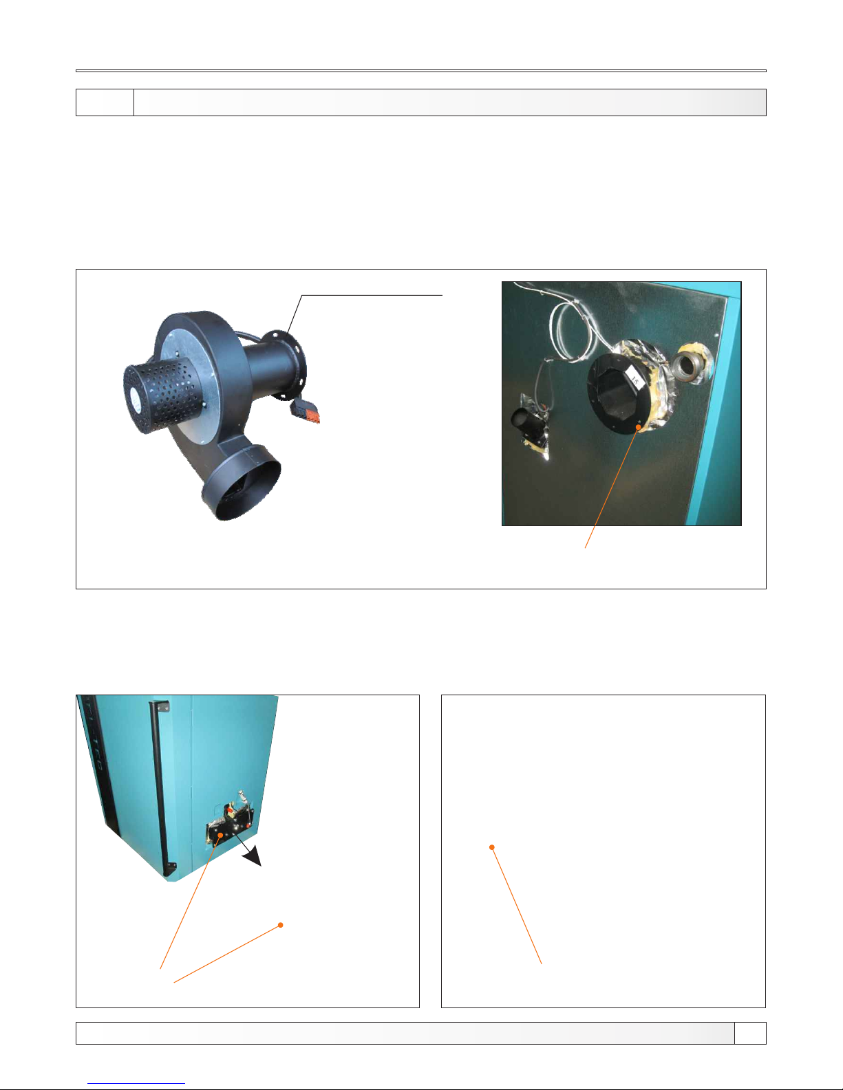
Mounting parts
1.5. MOUNTING COMP ONEN TS
Fan
- mount on the back of boiler, is obligatory to use the flange gaskets fan, fastened using M8 bolts and
nuts. Plug-connector for power supply fan and the fan tachometer in the back of the control box. Fan
output can be mounted in any directions.
Fan
(Fan output can be mounted in
any directions)
Flange for mounting
on the boiler
Flange for mounting fan
Mechanism for grating cleaning
- mount on the right side of the boiler (in this side is pellet tank), must be fastened using M8 bolts
and nuts. After assembly, it is necessary to attach the lever burner grid with gear motor trail.
Plug-in two cables with connectors (motor and microswitches).
For ease of handling, transport and import of boiler, PelTec / PelTec-lambda is delivered in parts that
need be mounted on the boiler when the boiler is in the boiler room. These parts need to be installed on
the boiler:
Flange for
mounting
mechanism
for self-cleaning
Flange for mounting on the boiler
7
Technical instructions PelTec / PelTec-lambda
Page 8
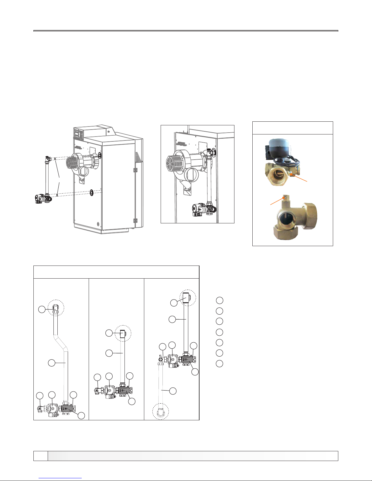
Positions of mounted components
Seal
Socket for temp.sensor
Socket
PelTec /
PelTec-lambda
12
Pump group
PelTec /
PelTec-lambda
18-36
PelTec /
PelTec-lambda
48
Example of installation pump group to the boiler PelTec/PelTec-lambda 18-36
Socket
1
1
1
2
3
4
5
6
2
3
4
5
6
2
4
3
5
6
7
*
*Only PelTec / PelTec-lambda 48
1 - Boiler pump P1
2 - Angled T-piece -return flow
3 - 3-way mixing valve
4 - Motor actuator
5 - Connecting pipe
6 - T-piece -flow
7 - Lower pipe
*
LEGEND:
Pump group
- mount pump group with 4-way mixing valve to the boiler so that the T-piece is in the upper side. On
the upper connector of the T-piece incorporate safety ventilation group. On the back of boiler were
prepared two holenders for mounting connection tubes (connection tubes with 4- way mixing valve).
Be sure to use the seal for holenders. Set return temperature sensor in the socket for the sensor
between the 4-way mixing valve and the boiler. It is obligatory using the included thermal paste.
Plug-in return flow sensor on the back of the box control. Connect the pump cable with connector to
the back of the control box. Mandatory set the 3-speed pump on the speed 3.
NOTE: check the tightness of connection tubes. Fasten connections binding tubes if necessary, so
that a good seal.
8
Technical instructions PelTec / PelTec-lambda
Page 9
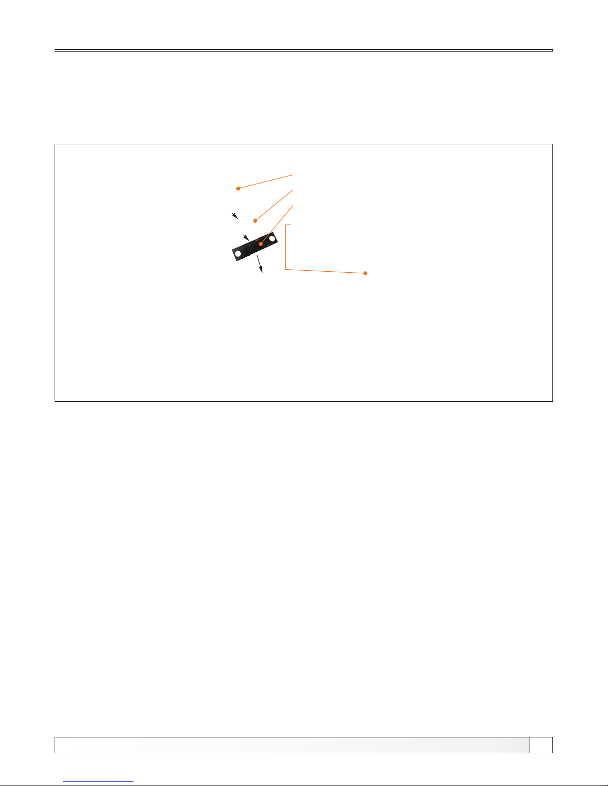
Pellet level in the tank sensor
- mount this sensor on the back side inside of the pellet tank. First set the plastic glass distance for
sensor. After that, put the sensor on this glass. Attach the sensor and the plastic distance with 4 screws
supplied. Attach protective cover. Plug-in the cable with connector of the pellet level sensor on the back
of the box control.
Protection cover
Pellet level sensor
Plastic pad
Mounted position (be
sure to attach the cable
with cable ties
Pellet tank
- mount pellet tank according installation manual for mounting pellet tank. Set up pellet transporter in
the pellet tank. Place the pellet tank to the boiler and set PVC tube to conveyor and tube
supply on the boiler. Set up the PVC tube so as to allow the smooth falling pellet into the burner. If
necessary, cut the PVC tube to the required length. Plug-in the power connector on the back of the
control box.
Positions of mounted components
9
Technical instructions PelTec / PelTec-lambda
Page 10
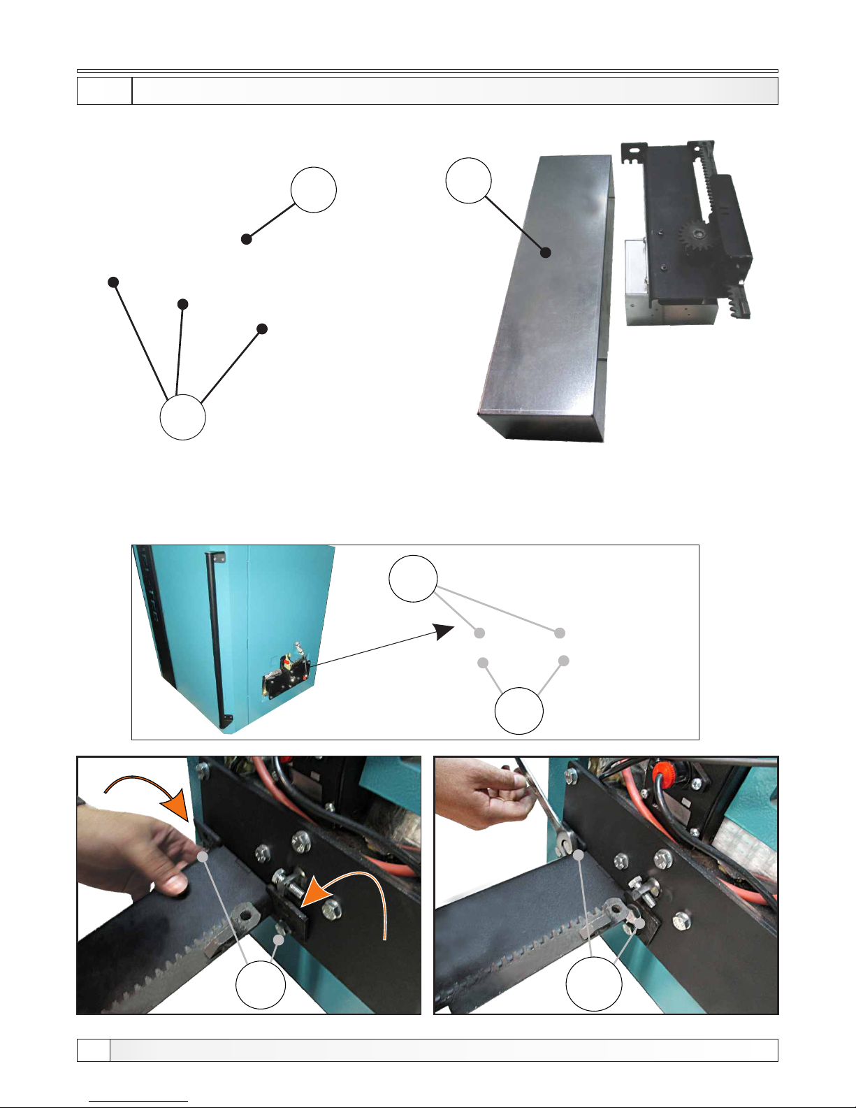
1.5.1 MOUNTI NG ME CHANISM F OR GRATE C LEANING
1. Remove the two screws (A), from cover (B) of the grate cleaning mechanism and remove cover
carefully .
A
B
B
2. Remove the two screws (C) and just slightly loosen screws (D) as shown in picture below .
Carefully attach grate cleaning mechanism to loose screws (D), then fasten with screws (C) and
tighten the screws (D).
C
D
C
D
Grate cleaning
10
Technical instructions PelTec / PelTec-lambda
Page 11
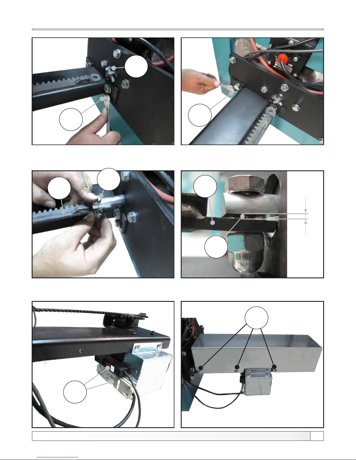
D
E
E
D
F
F
cca 1-2mm
G
A
3. Set the screw (E) into the jagged track (F), set the nut on the screw and tighten. Free space
(G) is required for the proper functioning of the mechanism.
4. Connect the connectors (H) so they have a good contact. Carefully set the cover and tighten with
the screws (A).
H
Grate cleaning
11
Technical instructions PelTec / PelTec-lambda
Page 12
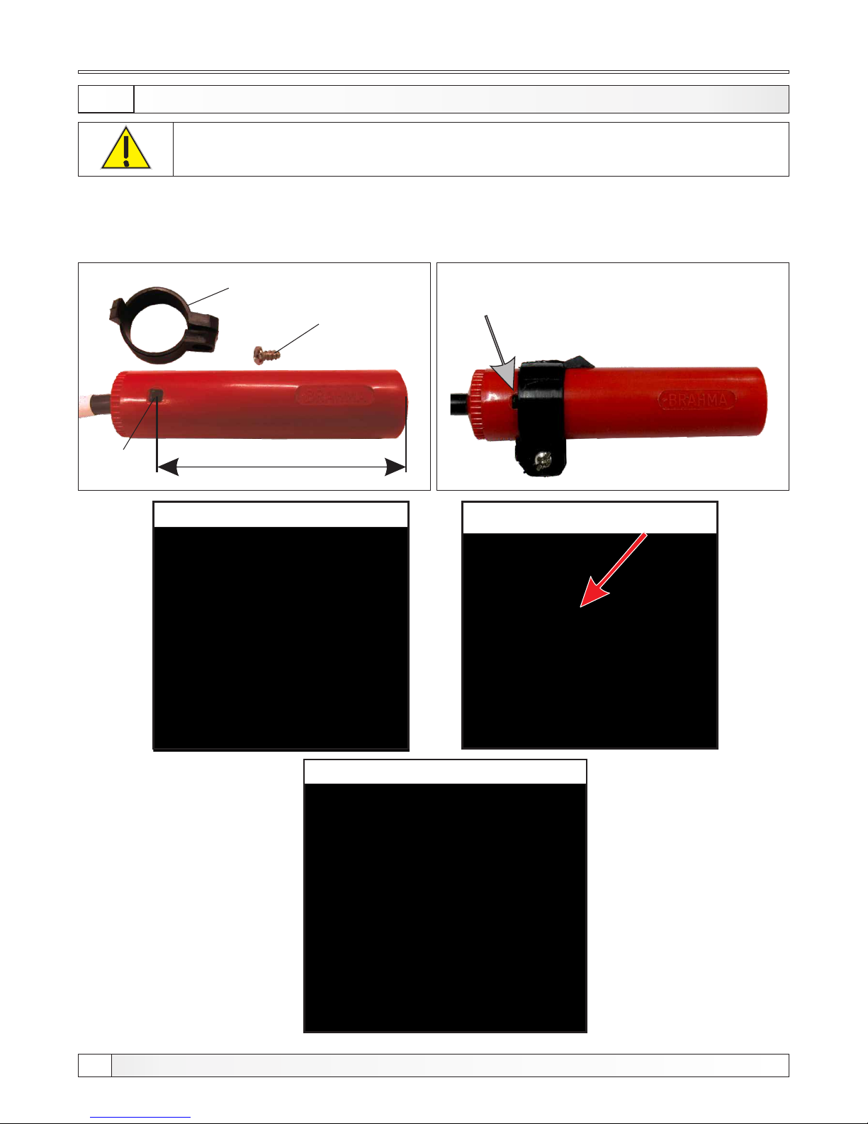
Setting photocell on the work position
Before first startup, be sure to set the photocell to the position as on
Figure 3, otherwise the boiler will not work properly!
Figure 2. Photocell position on delivery
57mm
The photocell should not be set too deep or too shallow in the box. So, limiter determines
the proper depth of photocell position. Make sure the limiter is set to black mark. Black
mark should be barely visible (see image below).
Limiter
Screw
Mark
The limiter must be set so that the black
mark is barely visible like is shown below
(partially covered by hose clamps)
Figure 3. Carefully put the photocell
until the plastic holder
Figure 4. Photocell ready to work
1.5.3 SETTIN G PHO TOCELL TO THE WORK POSIT ION
12
Technical instructions PelTec / PelTec-lambda
Page 13

1.6. SAFETY ELEMENTS
1.7. FUEL
Safety elements, fuel
Boiler have a few safety elements:
- Bimetal thermostat built on the burner pellet feeding tube. If the bimetal set temperature (80°C)
is exceeded, pellet feeding is stopped, the burner shuts down and the error E3 appears on the
control unit (LED diode switches on).
- If there is no flame (the built in photo-cell does not detect the flame within set time), control
stops the burner operation and error E2 is displayed or it goes to blowing off and error E6 is
- Displayed (LED diode switched on).Control unit has a built in protective function which protects the
boiler against overheating. If temperature in the boiler exceeds 93°C, regardless heating or
sanitary water is needed the boiler pump and/or the sanitary water turns on and works until
temperature in the boiler falls below 93°C.
- The fan has a built-in RPM counter and, if regulation is informed that the fan does not operate in
accordance with the requirement interrupts the process display fan error
- Drive for grate linear move have in-built two switches by wich control unit monitor position of grate.
If grate at given moment is not on provided place, control unit recieve information that grate is not
on provided place and interrupt proces and display information about grate error.
- Flue gas connection have in-built sensor for flue gas temperature meassuring. If flue gas tube
temperature is over 250°C, control unit interrupt proces and display information about too high flue
gas temperature.
When temperature in the boiler exceeds 110°C (+0°C / - 9°C), power supply is turned off by the
safety thermostat (via control unit).
Thermal protection built in coils of the fan electric motor at the burner and the screw feeder motor,
protects them against overheating caused by failure or locking.
A flexible tube connecting the pellet burner and pellet tank is made of plastic material reinforced with
metal wire which, in case of back flame from the burner to the tank, melts and prevents flame to
penetrate to the pellet tank.
Only wood pellets are used as fuel in PelTec / PelTec-lambda. Wooden pellets are bio-fuel made of
wooden wastes. Pellets can be packed in different packaging: in bags (15 kg or 1000 kg), or as bulk in
3
large (underground) tanks ( 4 - 15 m ) or in basement spaces. Recommended properties of pellets for
firing in PelTec / PelTec-lambda boilers are the following:
- heating value >= 5 kWh/kg (18 MJ/kg)
-diameter <= 6 mm
-max. moisture content <= 12 %
-max. dust content <= 1,5 %.
13
Technical instructions PelTec / PelTec-lambda
Page 14
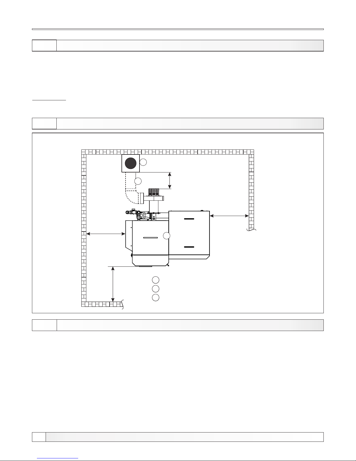
2.0. BOILER POSIT IONI NG AND ASSEMB LY
2.1. MINIMUM DISTA NCE FROM THE ROOM WALL S
Figure 5. Minimum distance from the room walls for PelTec / PelTec-lambda
1
Boiler PelTec / PelTec-lambda
Chimney
Flue (Chimney connection; must be insulated)
-
-
2
A = 6,02 x Q
Each boiler room must be equipped with an opening for supply of fresh air which is dimensioned in
accordance with boiler output (minimum opening area according to the below shown equation). Such
opening must be protected with a net or grate. All installation works have to be performed in accordance
with valid national and European standards. Boiler must not operate in flammable and explosive
environment.
2.2. OPENING FOR FRESH AIR (FRE SH AIR SUPP LY)
3
-
Boiler positioning, assembly and building in must be performed by a qualified person. We recommend that
boiler is placed on a concrete base with height of 50 to 100 mm above the floor. Boiler room must be frostproof and well ventilated. Boiler has to be positioned so that it can be properly connected to the chimney (see
Figure 2) and simultaneously, enabling tending of boiler and additional equipment, control during operation,
cleaning and maintenance.
WARNING!
Flammable items must not be placed on the boiler and within the minimum distances shown in
Figure 1.
Q - boiler output in kW
2
A - opening area in cm
1
-
-
2
3
-
min. 550 mm
min. 1000 mm
min. 450 mm
2
3
1
min. 300 mm
max 1500 mm
Boiler positioning
14
Technical instructions PelTec / PelTec-lambda
Page 15
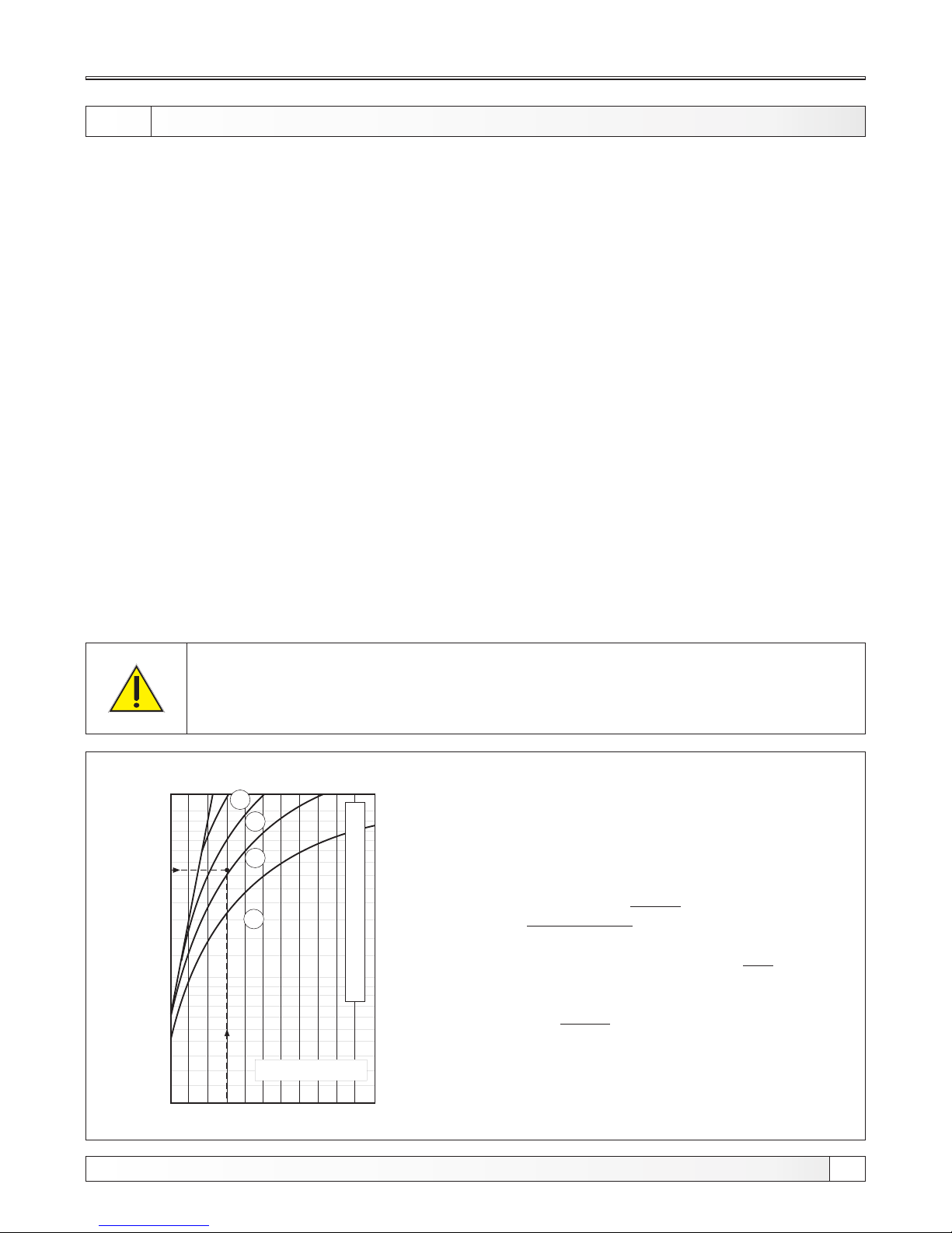
Figure 6. Dimensioning of the chimney for PelTec / PelTec-lambda
3.0. CONNECTION TO THE CHIMNEY
10
15
20
25
30
35
40
45
50
5 10 15
Wood pellets
15
16
18
20
6 7 8 9
The chimney must be resistant against flue condensate!
IProperly dimensioned and built chimney is the main condition for safe and economical
functioning of the boiler. The thermal insulation of the chimney has to be done properly, it has
to be absolutely gas-proof and smooth. On its lower part there has to be built in the opening for
cleaning with the door. An brick-layed chimney has to have three layers with an insulation of 30 mm
in the middle, if the chimney is built inside the house (i.e. inside the heated area), or an insulation of
50 mm if it is built outside the house (i.e. outside the heated area). The flue gas temperature has to
be at least 30°C higher then the temprerature of their consdensation point. The choice and the
construction of the chimney has to be performed by the authorized person. Inside dimensions of the
chimney intersection selected in accordance with diagram for chimney selection, they depend of its
height and of the capacity of the boiler.
Chimney must be dimenensioned by "diagram for chimney selection" and maximum permetted
lenght of connection flue gas tube between connection on fan and chimney is 2000 mm and
minimum light diameter xx0 mm with maximum two 90° bends. Connection flue gas tube can be
mounted horizontally or at any angle which allows to gas, on his way to chimney, a constant
increase of height with condidering of exit point from fan. Connection flue gas tube must have
openings for cleaning through which is possible to clean entire lenght of flue gas tube or must
ensure easy removal part of flue gas tube which allow complete cleaning of connection flue gas
tube. To prevent entry of condensate form chimney into the boiler, flue gas tube must be mounted 10
mm deeper into the chimney. Connection flue gas tube between fan and chimney must be insulated
with 30-50 mm mineral wool.
Connection to the chimney
Useful height of the chimney (m)
Rated thermal output of the boiler (kW)
Chimney light diameter (cm)
Chimney dimensioning example:
for boiler PelTec / PelTec-lambda 36
Boiler heat output: 36 kW
Fuel: wood pellets
Required usable chimney height: 7 m
Required chimney light
diameter: 18 cm
15
Technical instructions PelTec / PelTec-lambda
Page 16
In open system it is necessary to put an open expansion vessel min. 0,5 m above the height of the
highest heating body. If expansion vessel is located in a room without heating, it should be insulated.
The system pump could be connected on the inline or back line of the boiler.
4.1.1. CONNECTION TO OPEN HEATING SYSTEM
4.1. CONNECTION TO CENTRAL HEATING SYSTEM
All installation work must be made in accordance with valid national and European standards.
Boiler PelTec / PelTec-lambda can be built in closed and open central heating systems. In both cases
boiler can be fired with wood pellets. Installation has to be made, in according to technical standards, by
a professional who will be responsible for proper boiler operation. Before connecting boiler to central
heating system, the system has to be flushed to remove impurities remaining after system installation. It
prevents boiler overheating, noise within the system, disturbances at a pump and mixing valve. Boiler
should always be connected to central heating system by connectors, never by welding. Figure 1.
shows safe distances required for boiler cleaning and maintenance.
4.0. INSTALLATION
All local regulations, including those referring to national and European standards need to be complied
with when installing the appliance.
Installation, connection to central heating system
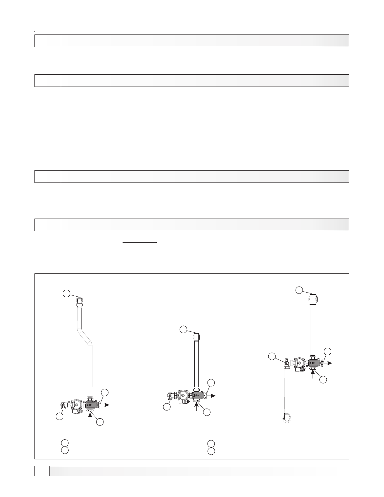
4.1.2. CONNECTION TO CLOSED HEATING SYSTEM
In closed heating system it is obligatory to build in certified safety valve with opening pressure of 2,5 bar
and a membrane expansion vessel. Safety valve and expansion vessel must be built in accordance with
professional rules and between safety valve and expansion vessel and boiler must not be any valve.
Schemes for possible configurations are on following pages.
Figure 7. Connections to connect the boiler to a closed heating system
PelTec /
PelTec-lambda
12
PelTec /
PelTec-lambda
18-36
PelTec /
PelTec-lambda
48
1
2
4
3
1 - Safety ventilation group connection
2 - Expansion vessel connection
1
3
4
2
2
3
4
1
3 - Main flow to installation
4 - Return flow from installation
16
Technical instructions PelTec / PelTec-lambda
Page 17
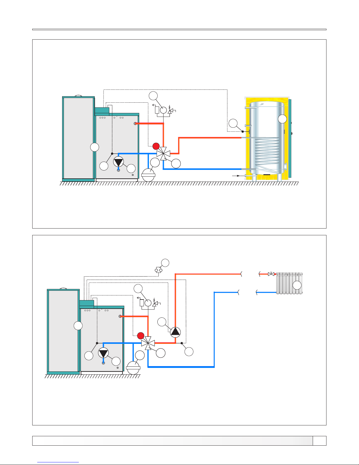
3
6
bar
2
4
5
1 - Boiler PelTec / PelTec-lambda
2 - Air self-venting group 2,5 bar
3 - Motor 4-ways mixing valve
4 - Closed type expansion vessel
5 - Return flow sensor
6 - Flow temperature sensor
7 - Heating circuit
8 - Room thermostat
P1
1 - Boiler PelTec / PelTec-lambda
2 - Air self-venting group 2,5 bar
3 - Motor 4-ways mixing valve
4 - Closed type expansion vessel
5 - Return flow sensor
6 - DHW tank
7 - DHW sensor
3
M
bar
2
4
5
HV
P1
6
1
1
M
P2
7
7
8
Required sensors: - return flow temp. sensor
- DHW sensor
Required sensors: - return flow temp. sensor
- flow temperature sensor
Configuration DHW, DHC
Scheme 1. Configuration DHW
Scheme 2. Configuration DHC
17
Technical instructions PelTec / PelTec-lambda
Page 18
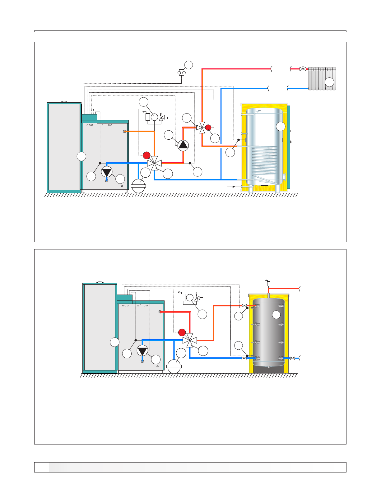
1 - Boiler PelTec / PelTec-lambda
2 - Air self-venting group 2,5 bar
3 - Motor 4-ways mixing valve
4 - Closed type expansion vessel
5 - Return flow sensor
6 - Flow sensor
7 - DHW tank
8 - DHW tank sensor
9 - Heating circuit
10 - 3-way diverter valve
11 - Room thermostat
3
M
6
bar
2
4
5
HV
P2
P1
7
1
9
P
1 - Boiler PelTec / PelTec-lambda
2 - Air self-venting group 2,5 bar
3 - Motor 4-ways mixing valve
4 - Closed type expansion vessel
5 - Back flow sensor
6 - Accumulation tank CAS
7 - Accumulation tank sensor CAS 1 (upper)
8 - Accumulation tank sensor CAS (lower)
3
bar
2
4
5
P1
6
7
8
1
M
P3
10
8
11
Required sensors: - return flow temp. sensor
- flow temperature sensor
- DHW sensor
Required sensors: - return flow temp. sensor
- accumulation tank sensor (upper)
- accumulation tank sensor (lower)
Configuration DHC || DHW, BUF
Scheme 3. Configuration DHC || DHW
Scheme 4. Configuration BUF
NOTES:
- In this configuration is possible to upgrade up to 4 unit "CM2K-P module for regulation 2 heating circuits“.
- In this configuration is possible to connect external control (external start)
18
Technical instructions PelTec / PelTec-lambda
Page 19
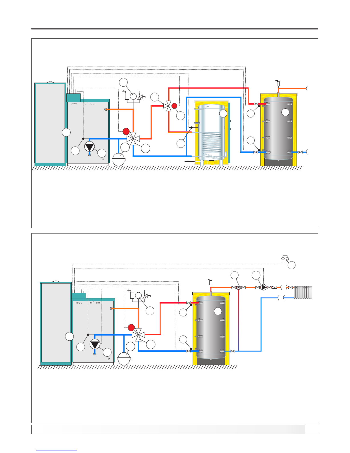
1 - Boiler PelTec / PelTec-lambda
2 - Air self-venting group 2,5 bar
3 - Motor 4-ways mixing valve
4 - Closed type expansion vessel
5 - Return flow sensor
6 - DHV tank
7 - DHW tank sensor
8 - Accumulation tank CAS
9 - Accumulation tank sensor CAS 1 (upper)
10 - Accumulation tank sensor CAS 2 (lower)
11 - 3-way diverter valve
3
M
bar
2
4
5
HV
P1
1
P
P3
11
7
8
9
10
6
1 - Boiler PelTec / PelTec-lambda
2 - Air self-venting group 2,5 bar
3 - Motor 4-ways mixing valve
4 - Closed type expansion vessel
5 - Return flow sensor
6 - Accumulation tank CAS
7 - Accumulation tank sensor CAS 1 (upper)
8 - Accumulation tank sensor CAS 2 (lower)
9 - 3-way manual mixing valve
10 - Room thermostat
bar
2
4
5
P1
9
10
6
7
8
1
3
M
P2
Required sensors: - return flow temp. sensor
- DHW tank sensor
- accumulation tank sensor (upper)
- accumulation tank sensor (lower)
Required sensors: - return flow temp. sensor
- accumulation tank sensor (upper)
- accumulation tank sensor (lower)
Configuration DHW || BUF, BUF -- IHC
Scheme 5. Configuration DHW || BUF
Scheme 6. Configuration BUF -- IHC
NOTE:
In this configuration is possible to upgrade up to 4 unit "CM2K-P module for regulation 2 heating circuits“.
19
NOTES:
- In this configuration is possible to upgrade up to 4 unit "CM2K-P module for regulation 2 heating circuits“.
- In this configuration is possible to connect external control (external start)
Technical instructions PelTec / PelTec-lambda
Page 20
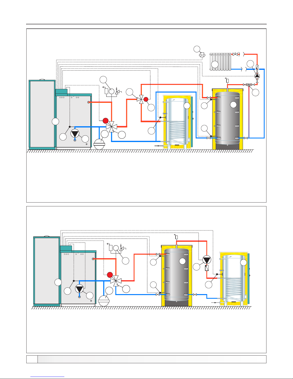
1 - Boiler PelTec / PelTec-lambda
2 - Air self-venting group 2,5 bar
3 - Motor 4-ways mixing valve
4 - Closed type expansion vessel
5 - Return flow sensor
6 - DHV tank
7 - DHV tank sensor
8 - Accumulation tank CAS
9 - Accumulation tank sensor CAS 1 (upper)
10 - Accumulation tank sensor CAS 2 (lower)
11 - Heating circuit
12 - 3-way diverter valve
13 - 3-way manual mixing valve
14 - Room thermostat
3
M
bar
2
4
5
HV
P1
1
P
P3
12
7
8
9
10
6
11
13
1 - Boiler PelTec / PelTec-lambda
2 - Air self-venting group 2,5 bar
3 - Motor 4-ways mixing valve
4 - Closed type expansion vessel
5 - Return flow sensor
6 - Accumulation tank CAS
7 - Accumulation tank sensor CAS 1 (upper)
8 - Accumulation tank sensor CAS 2 (lower)
9 - DHV tank
10 - DHV tank sensor
bar
2
4
5
P1
6
7
8
1
3
M
P2
HV
9
P3
10
14
Required sensors: - return flow temp. sensor
- DHW tank sensor
- accumulation tank sensor (upper)
- accumulation tank sensor (lower)
Required sensors: - return flow temp. sensor
- DHW tank sensor
- accumulation tank sensor (upper)
- accumulation tank sensor (lower)
Configuration DHW || BUF -- IHC, BUF -- DHW
Scheme 7. Configuration DHW || BUF -- IHC
Scheme 8. Configuration BUF -- DHW
NOTE:
In this configuration is possible to upgrade up to 4 unit "CM2K-P module for regulation 2 heating circuits“.
20
Technical instructions PelTec / PelTec-lambda
NOTES:
- In this configuration is possible to upgrade up to 4 unit "CM2K-P module for regulation 2 heating circuits“.
- In this configuration is possible to connect external control (external start)
Page 21
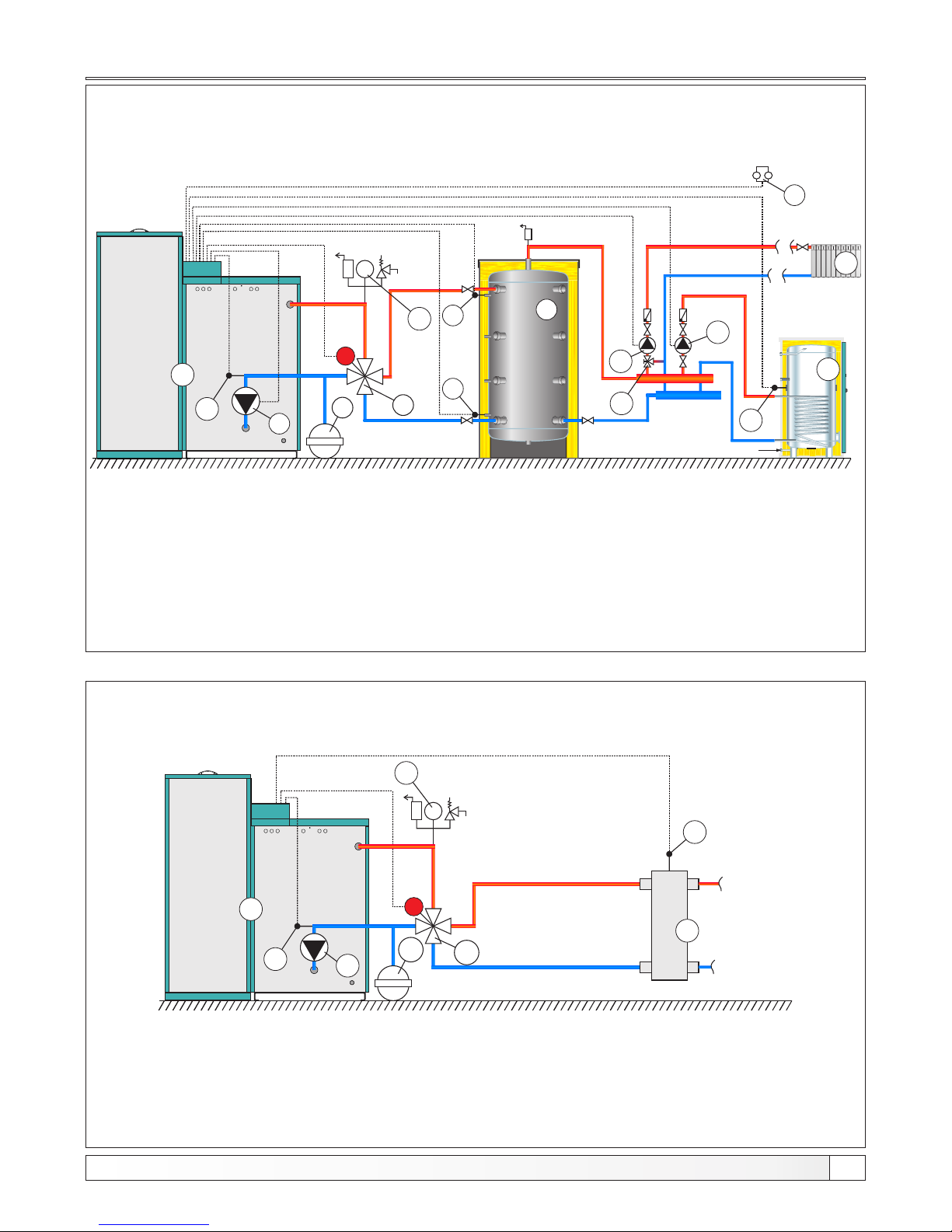
1 - Boiler PelTec / PelTec-lambda
2 - Air self-venting group 2,5 bar
3 - Motor 4-ways mixing valve
4 - Closed type expansion vessel
5 - Return flow sensor
6 - Accumulation tank CAS
7 - Accumulation tank sensor CAS 1 (upper)
8 - Accumulation tank sensor CAS 2 (lower)
9 - DHV tank
10 - DHV tank sensor
11 - Heating circuit
12 - 3-way manual mixing valve
13 - Room thermostat
bar
2
5
P1
13
7
8
HV
9
P3
P2
6
3
4
M
12
1
11
10
1 - Boiler PelTec / PelTec-lambda
2 - Air self-venting group 2,5 bar
3 - Motor 4-ways mixing valve
4 - Closed type expansion vessel
5 - Return flow sensor
6 - Hydraulic crossover
7 - Hydraulic crossover sensor
3
M
bar
2
4
5
P1
1
7
6
Required sensors: - return flow temp. sensor
- DHW tank sensor
- accumulation tank sensor (upper)
- accumulation tank sensor (lower)
Required sensors: - return flow temp. sensor
- hydraulic crossover sensor
Configuration BUF -- IHC || DHW, CRO
Scheme 9. Configuration BUF -- IHC || DHW
Scheme 10. Configuration CRO
21
NOTES:
- In this configuration is possible to upgrade up to 4 unit "CM2K-P module for regulation 2 heating circuits“.
- In this configuration is possible to connect external control (external start)
NOTES:
- In this configuration is possible to upgrade up to 4 unit "CM2K-P module for regulation 2 heating circuits“.
- In this configuration is possible to connect external control (external start)
Technical instructions PelTec / PelTec-lambda
Page 22
Scheme 12. Configuration DHC || DHW(2)
Configuration CRO / BUF, IHC || DHW (2)
1 - Boiler PelTec / PelTec-lambda
2 - Air self-venting group 2,5 bar
3 - Motor 4-ways mixing valve
4 - Closed type expansion vesse
5 - Return flow sensor
6 - Flow sensor
7 - DHW tank
8 - DHW tank sensor
9 - Heating circuit
10 - Room thermostat
11 - Hydraulic crossover
Required sensors: - return flow temp. sensor
- flow temperature sensor
- DHW sensor
Scheme 11. Configuration CRO / BUF
3
bar
2
4
5
P1
6b
7
8
1
M
Version 1: (display shows 1 temperature, eg hidraulic crossover)
3
M
bar
2
4
5
P1
1
9
6a
Version 2: (Display shows 2 temperatures (eg. accumulation tank)
1 - Boiler PelTec / PelTec-lambda
2 - Air self-venting group 2,5 bar
3 - Motor 4-ways mixing valve
4 - Closed type expansion vessel
5 - Return flow sensor
6a - Hydraulic crossover
6b - Accumulation tank
7 - Accumulation tank sensor 1 (upper)
8 - Accumulation tank sensor 2 (lower)
9 - Hydraulic crossover sensor
Note: Connecting the sensor 9 (version 1) and 7,8 (version 2) is not required because these temperatures
are only informative, if sensors are not connected, regulation will show temperature " - °C". The boiler
regulation will not report any error even if the sensors are defective.
- manually (ON/OFF)
- by scheduled starting times
- by external controller(START/STOP)**
- by cascade manager *
- by external controller (start/stop) + cascade manager**
Possible control:
- by room thermostat
Imposible control:
Additional equipment.
NOTE: USED ONLY IN CASCADES AND EXTERNAL CONTROL
Required sensors: - return flow temp. sensor
- hydraulic crossover sensor (only in version 1)
- accumulation tank sensor (upper)(only in version 2)
- accumulation tank sensor (lower)
*
**
22
Technical instructions PelTec / PelTec-lambda
NOTES:
- In this configuration is possible to upgrade up to 4 unit "CM2K-P module for regulation 2 heating circuits“.
- In this configuration is possible to connect external control (external start)
3
M
bar
2
4
5
HV
P1
7
1
9
P3
8
10
P2
11
Page 23
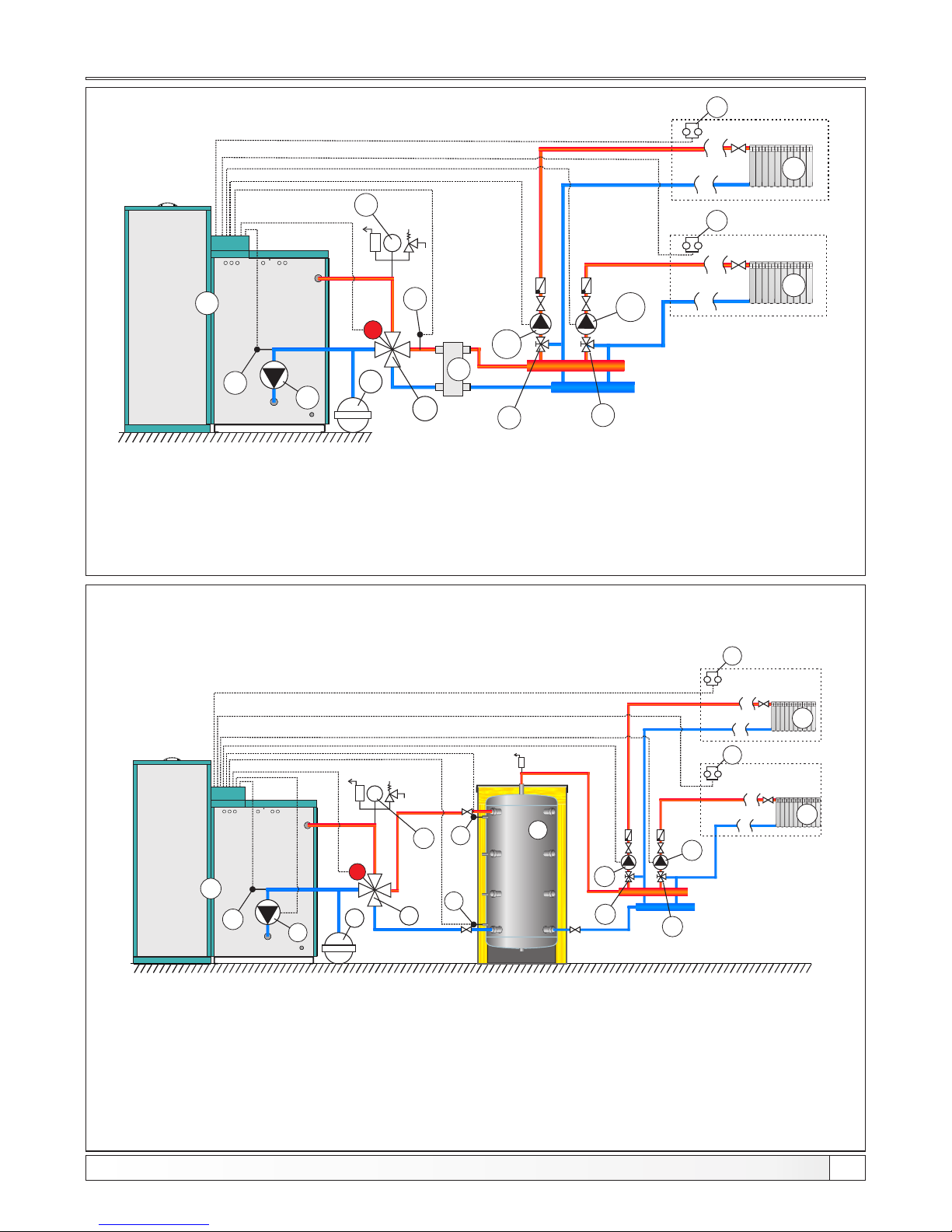
1 - Boiler PelTec / PelTec-lambda
2 - Air self-venting group 2,5 bar
3 - Motor 4-ways mixing valve
4 - Closed type expansion vessel
5 - Return flow sensor
6 - Accumulation tank CAS
7 - Accumulation tank sensor CAS 1 (upper)
8 - Accumulation tank sensor CAS 1 (lower)
9 - Heating circuit 1
10 - 3-way manual mixing valve 1.circuit
11- Heating circuit 2
12- 3-way manual mixing valve 2.circuit
13- Room thermostat 1. circuit
14- Room thermostat 2. circuit
bar
2
5
P1
14
7
8
P3
P2
6
3
4
M
10
1
11
9
12
13
2. heating circuit
1. heating circuit
Required sensors: - return flow temp. sensor
- accumulation tank sensor (upper)
- accumulation tank sensor (lower)
Configuration DHC 2X, BUF--IHC 2X
Scheme 13. Configuration DHC 2X
Shema 14. Configuration BUF--IHCX2
1 - Boiler PelTec / PelTec-lambda
2 - Air self-venting group 2,5 bar
3 - Motor 4-ways mixing valve
4 - Closed type expansion vessel
5 - Return flow sensor
6 - Main flow temperature sensor
7 - Heating circuit 1
8 - 3-way manual mixing valve 1.circuit
9 - Heating circuit 2
10 - 3-way manual mixing valve 2.circuit
11- Room thermostat 1. circuit
12- Room thermostat 2. circuit
13 - Hydraulic crossover
Required sensors:
- return flow temp. sensor
- main flow temperature sensor
23
NOTES:
- In this configuration is possible to upgrade up to 4 unit "CM2K-P module for regulation 2 heating circuits“.
- In this configuration is possible to connect external control (external start)
Technical instructions PelTec / PelTec-lambda
3
bar
2
4
5
P1
1
M
12
P3
P2
10
9
7
8
2.krug grijanja
1.krug grijanja
11
6
13
Page 24
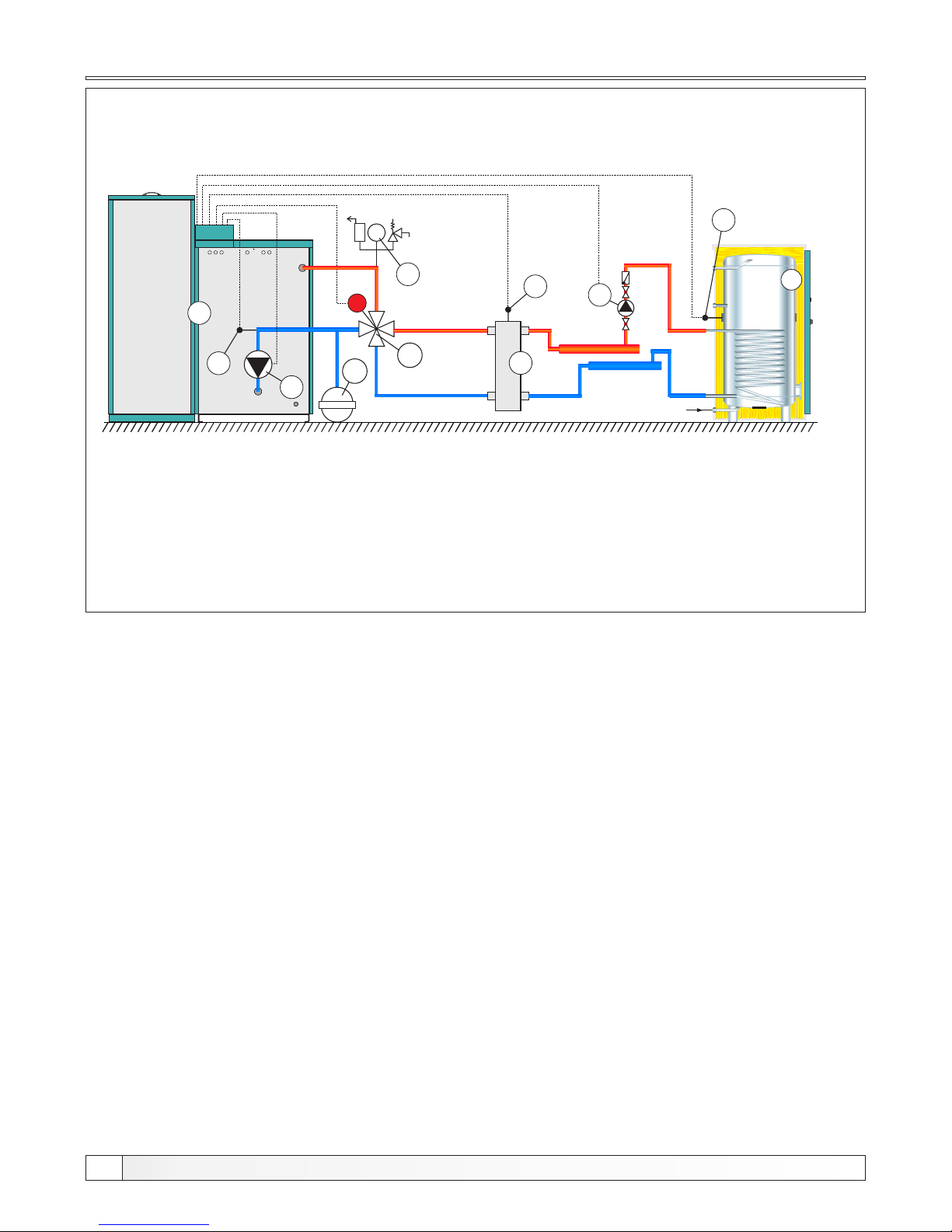
Configuration CRO / DHW
1 - Boiler PelTec / PelTec-lambda
2 - Air self-venting group 2,5 bar
3 - Motor 4-ways mixing valve
4 - Closed type expansion vessel
5 - Return flow sensor
6 - Hydraulic crossover
7 - Hydraulic crossover sensor
8 - DHW tank
9 - DHW tank sensor
bar
2
4
5
P1
1
3
M
8
9
Required sensors: - return flow temp. sensor
- DHW tank sensor
- hydraulic crossover sensor
Scheme 15. Configuration CRO -- DHW
7
6
P3
NOTE:
In this configuration is possible to upgrade up to 4 unit "CM2K-P module for regulation 2 heating circuits“.
24
Technical instructions PelTec / PelTec-lambda
Page 25
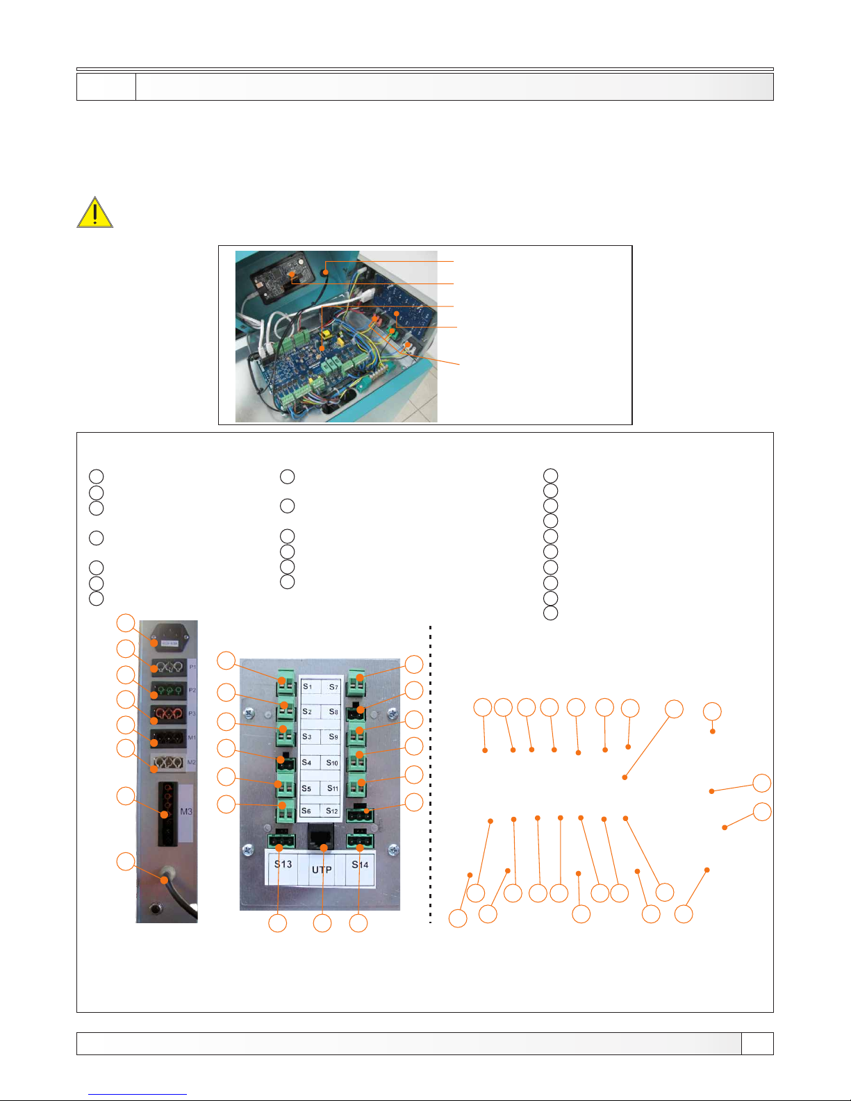
Electrical connections
5.0. ELECTRICAL CONNEC TION S
All electrical works must be performed by a certified professional in accordance with valid national and
European standards. If the supply cord is damaged, it must be replaced by the manufacturer, its service
agent or similarly qualified persons in order to avoid a hazard. A device for switching of all power supply
poles must be installed in electrical installation in accordance with the national regulations on electrical
installations. Pump of heating system should be connected to boiler control unit PelTec / PelTec-lambda .
CAUTION: When connecting any electrical part be sure to unplug the boiler at the main
switch and disconnect the power supply.
Figure 8. Connectors for power supply, el. components and sensors
S1* - Sanitary water sensor
Room thermostat 2.circuit
S2 - Accumulation tank 1 sensor (up) /
Hydraulic crossover sensor
S3 - Accumulation tank 2 sensor (down)
S4 - Flue gas sensor
S5 - Outside temp. sensor
S6 - Flow sensor / External control **
8
9
10
11
12
13
1
2
3
4
5
6
7
POWER SUPPLY
M1 - Pellet feeder
M2 - Actuator for 4-way
mixing valve
M3 - Fan
P1 - Heating pump
P2 - Domestic water pump
P3 - Tank pump
S7 - Return sensor
S8 - tube bimetal sensor PVC
S9 - Room thermostat / External control**
S10 - Alarm 1
S11 - Alarm 2 / Reserve
S12 - Pellet level in the tank sensor
- UTP connector
- Reserve
- Reserve
- Lambda probe cable
14
15
16
17
18
19
20
21
22
23
3
5
6
7
2
4
1
23
14
1615
8
1
2
3
5
13
6
1211
109
7
18 19
17
20
4
22
21
23
8
9
10
11
12
14
15
16
17
18
13
19
2021 22
Note: It is obligatory mount the sensor in the socket for sensors using thermal paste
* If heating system contains DHW, on the connector S1 is connected hot water sensor, and if the heating system
contains 2 heating circuit, on the connector S1 is connected the room thermostat.
**External control can be connected only in configurations: 4: BUF, 6: BUF--IHC, 8: BUF--DHW, 9: BUF-IHC||DHW,
10: CRO, 14: BUF--IHCX2 into the connector S6 and configuration 11:CRO/BUF into connector S9.
***
Only PelTec-lambda
*
**
**
***
The main switch
Display
The main electronic board
Electronic board inputs
Connectors for pump /
diverter valve
25
***
***
Technical instructions PelTec / PelTec-lambda
Page 26
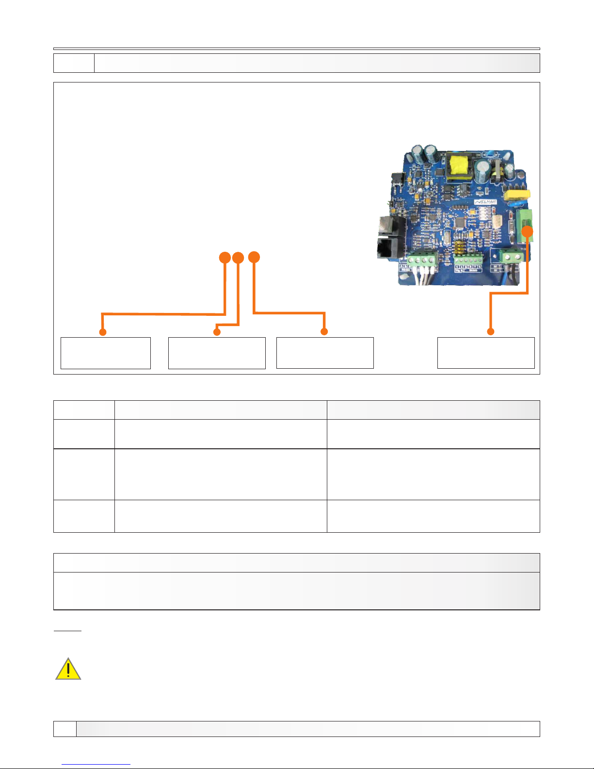
Main Board
PelTec / PelTec-lambda
Lambda board
(only PelTec-lambda)
*
Fuses
5.1. FUSES
MAIN BOARD
MARK
FUSE DEVICES
F1
fast acting fuse 3,15 A
LAMBDA BOARD (only PelTec-lambda)
MARK
FUSE DEVICES
F1
fast acting fuse 3,15 A
- all pumps
- regulation (power supply)
F2
fast acting fuse 500 mA
- all other devices who are not on the F1
and F3 (motor mechanism for the grating
self-cleaning, pellet conveyor motor, flu
gas tube cleaning motor...)
F3
medium slow fuse 3,15 A
- heater
- fan
IMPORTANT:
When replacing a fuse, be sure turn off the boiler at the main switch and unplug the power cord.
Note:
Be sure to use fast acting fuses!
*
26
Technical instructions PelTec / PelTec-lambda
Mark: F3
Mark: F2
Mark: F1
Medium slow
fuse 3,15 A
Fast acting fuse 500mA Fast acting fuse 3,15A
Mark: F1
Fast acting fuse 3,15A
- lambda probe power supply
Page 27
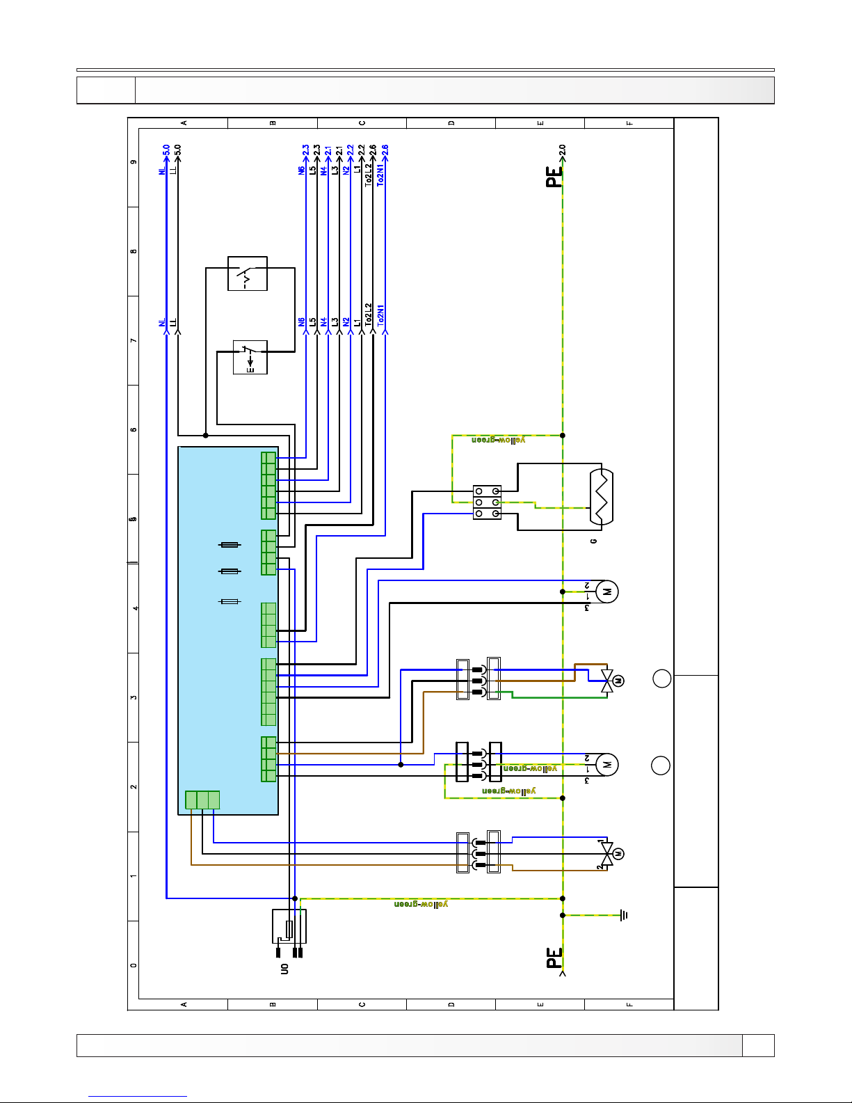
Electrical scheme (PelTec)
5.2.a ELECT RICA L SCH EME OUTPUTS 1 (PelTec)
27
Technical instructions PelTec / PelTec-lambda
CENTROMETAL
L
6, 3 A
N
PE
L1 N
3P CR NI
MUŠK I
3P CR NI
ŽENS K I
NL1
L1 N
3P BI J EL I
MUŠK I
3P BI J EL I
ŽENS K I
NL1
L1 N
L1 N
3P BI JE L I
MUŠK I
M1
M 2
PELLET
CONVEYOR
MOTOR
MIXING VALVE
ACTUATOR
FLU GAS
TUBE
CLEANING
MOTOR
ELECTRIC
HEATER
MAIN
SWITCH
SAFETY
THERMOSTAT
Connector
3-bit
white
Connector
3-bit
white
Connector
3-bit
black
Connector
3-bit
black
Connector
3-bit
white
Connector
3-bit
white
Terminal
block
brown
black
blue
black
blue
black
blue
blue blue
black
blue
blue
black
TO 1
T O 3
POW 1
L LL t L t L t L t L t L t L t L t L t L t L tN N N NN N N N NLp Lp
TO 2
TO 4
L t NLt
TO 5
black
blue
blue
black
blue
black
black
blue
black
blue
black
blue
blue
black
black
blue
brown
brown
crna
green
blue
smeđa
SMS motor
mechanism for
the grating
self-cleaning
1 2 3
1 2 3 4 1 2 3 4 5 6
1 2 3 4 1 2 3 4
1 2 3 4 5 6
S C H E M A - Control unit
PelTec
PelTec
OUTPUTS
F3
medium
slow
3,15A
F2
fast
500mA
F1
fast
3,15A
Page 28
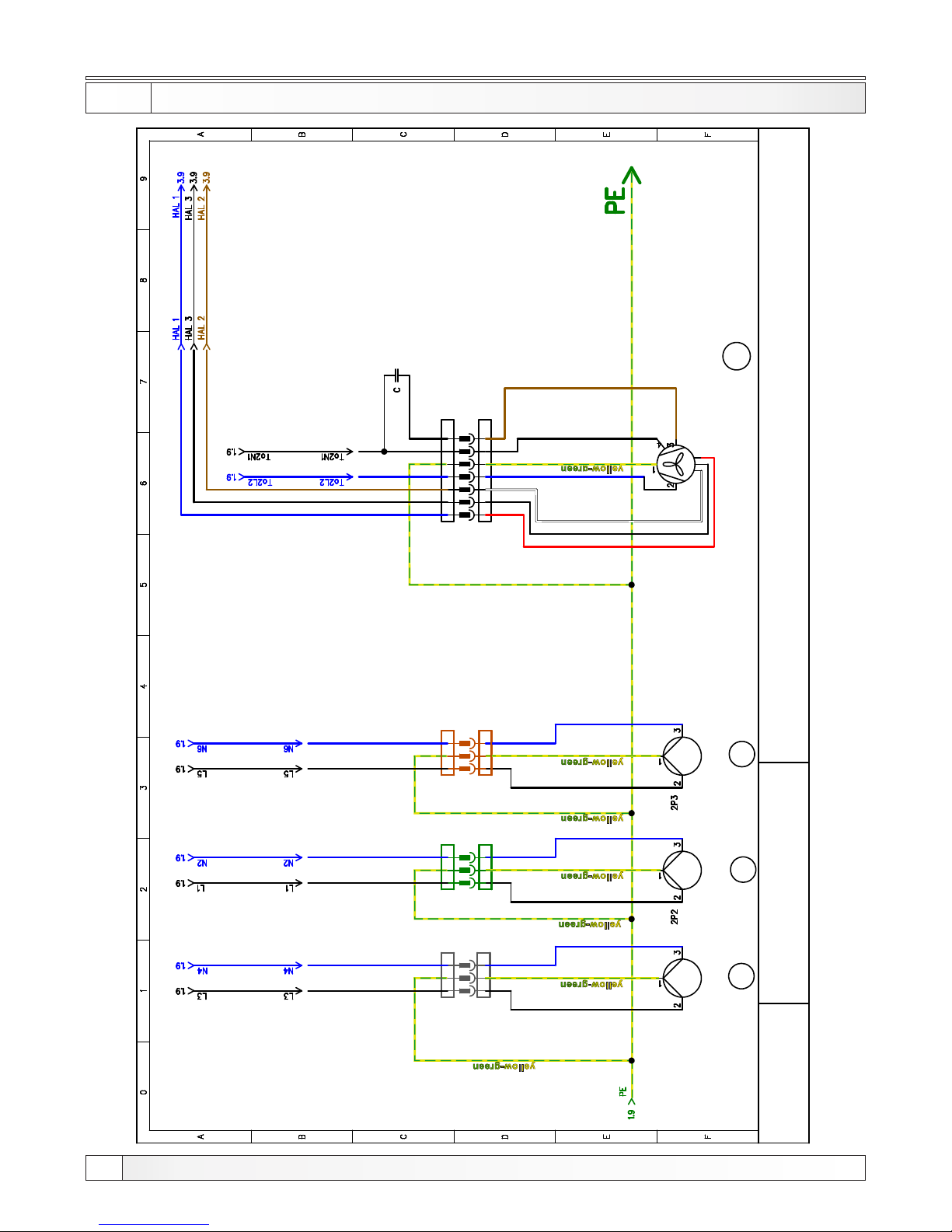
Electrical scheme (Peltec)
5.3.a ELECT RICA L SCH EME OUTPUTS 2 (PelTec)
28
Technical instructions PelTec / PelTec-lambda
L1 N
3P SI V I
MUŠK I
3P SI V I
ŽENS K I
NL1
L1 N
3P Z EL E NI
MUŠK I
L1 N
3P SMĐEI
MUŠK I
L1 N
7P CR / SM
MUŠK I
T1 T 2 S 3 B 4
7P CR / SM
ŽENS K I
NL1 T1 T 2 S 3 B 4
M 3
P1
P 2
P 3
3P SMĐEI
ŽENS K I
NL1
3P Z EL E NI
ŽENS K I
NL1
PUMP
P1
PUMP
P2
PUMP
P3
blue
black
blue
black
blue
black
Connector
3-pin
grey
blue
black
blue
Connector
3-pin
green
Connector
3-pin
brown
Flue gas fan with
RPM (rotates per min) sensor
black
black
blue
blue
black
red
white
blue
black
brown
Connector
7-pin
black/brown
S C H E M A - Control unit
PelTec
blue
brown
PelTec 12-24 C=2uF
PelTec 36-48 C=2,5uF
CENTROMETAL
black
Page 29
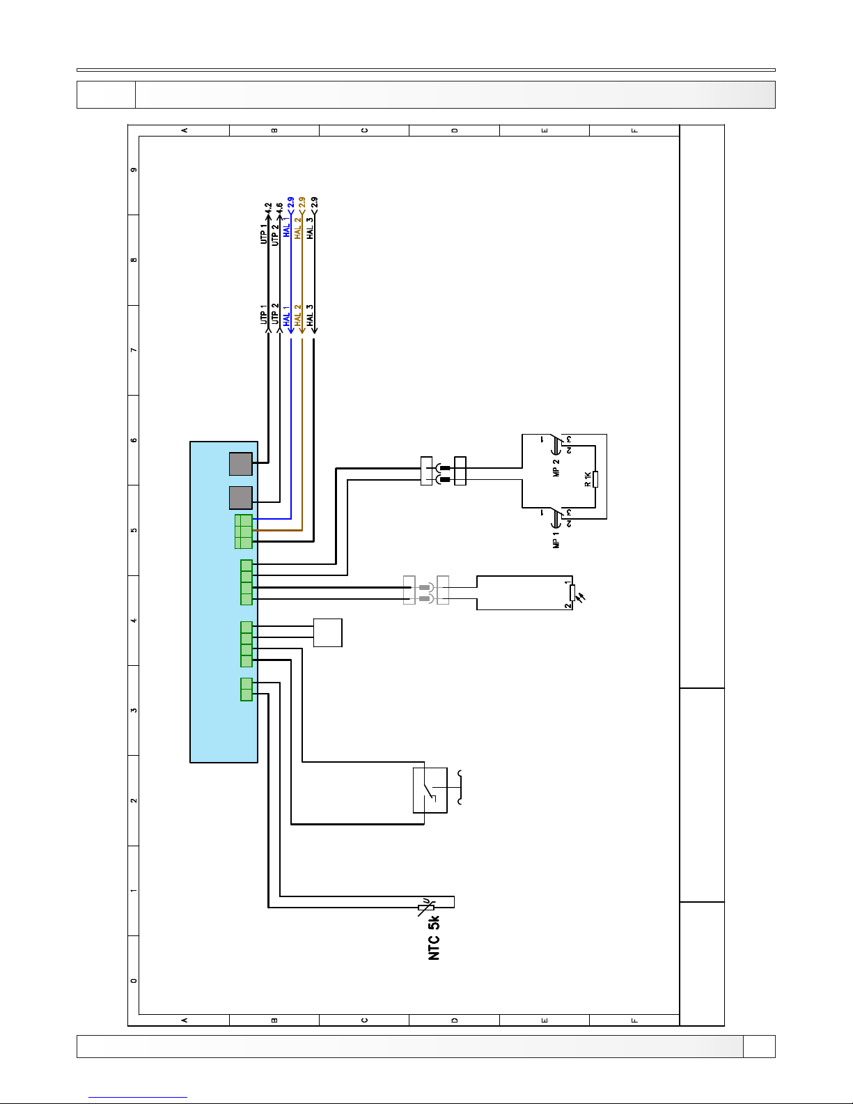
Electrical scheme (PelTec)
5.4.a ELECT RICA L SCH EME INPUTS (PelTec)
29
Technical instructions PelTec / PelTec-lambda
CENTROMETAL
2 1
2P SI V I
MUŠK I
2P SI V I
ŽENS K I
2 1
1
2
3
PelTec - INPUTS
Ai 1 Ai 3 Ai 2
HAL 1
24
+5 V
SI G
UTP1UTP2
BOILER
SENSOR
CODE FOR
BOILER
POWER
PRESOSTAT
Photocell
SHEMA Control unit
PELTEC
blue
black
brown
Connector
2-bit
grey
1
12
3
24
1
3
1
2
3
2P C RNI
ŽENS K I
2 1
2 1
2P CR NI
MUŠK I
MICROSWITCHES
FOR MOTOR
MECHANISM
FOR THE SELF-CLEANING
Connector
2-bit
black
GND
Page 30
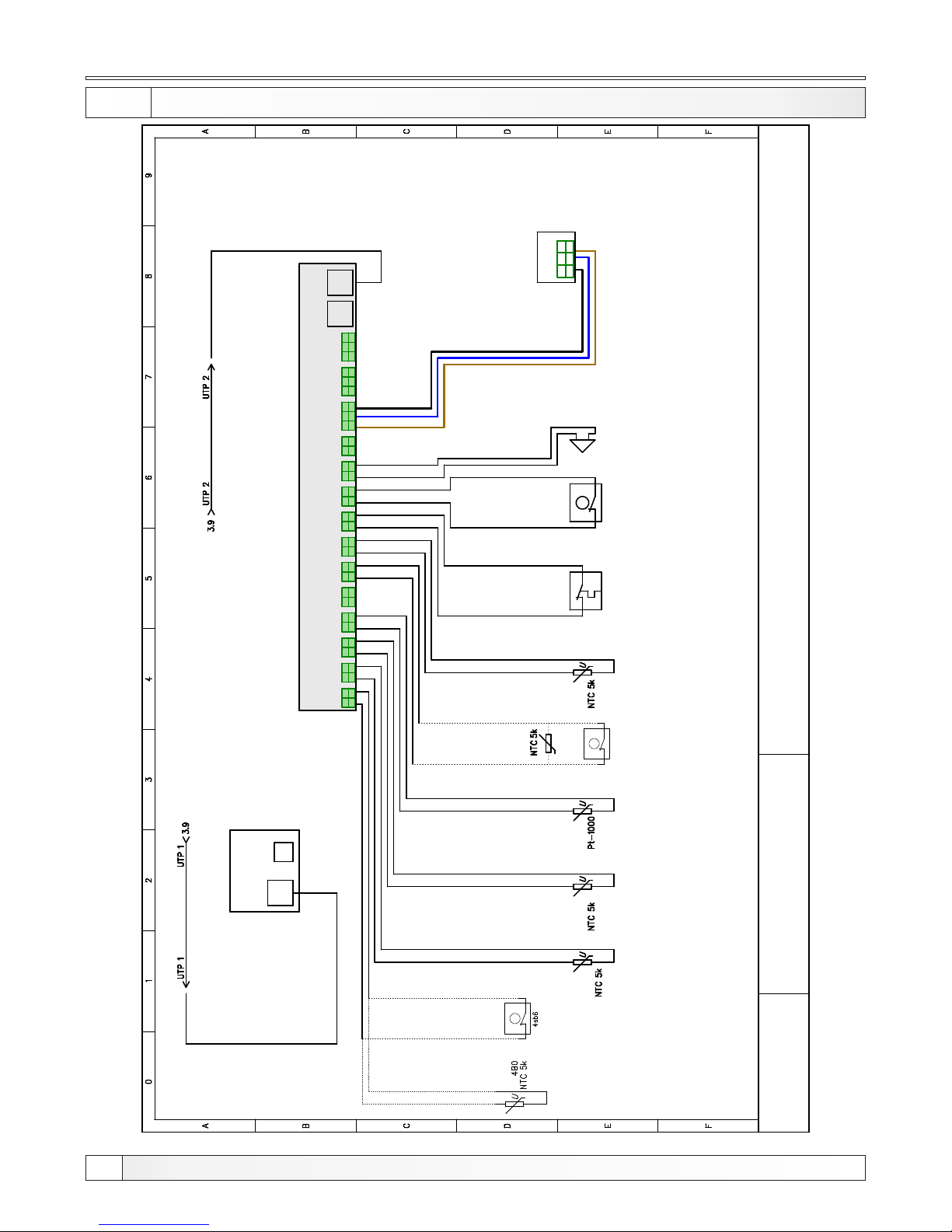
Electrical scheme (PelTec)
5.5.a ELECTRICA L SCH EME SENSORS (PelTec)
30
Technical instructions PelTec / PelTec-lambda
CENTROMETAL
U T P
US B
U T P CABLE
U T P CABLE
1 2
SIG
GND
1 2
SIG
GND
1 2
SIG
GND
1 2
SIG
GND
1 2
SIG
GND
1 2
SIG
GND
1 2
SIG
GND
1 2
SIG
GND
1 2
SIG
GND
1 2
SIG
GND
1 2
SIG
GND
1 2
SIG
GND
1 2
+5 V
3
GND
SIG
UT P 1 U TP 2
1 2
+5V
3
GND
SIG
1 2
+5V
3
GND
SIG
S C H E M A - Control unit
PelTec
PelTec - SENSORS
PelTec Display
PELLET LEVEL IN
THE TANK SENSOR
3 2
+5 V
1
GND
SIG
S1 S2 S3 S4 S5 S6 S7 S8 S9 S10 S11 S12 S13 S14
blue
black
brown
Room thermostat
for second heating
circuit
or
DHW
sensor
Depending
on the type
of installation
heating
S1
Accumulation
tank 1 sensor
(up)
/
Hydraulic
crossover
sensor
S2
Accumulation
tank 2 sensor
(down)
S3
Flue
gas
sensor
S4
The flow
sensor /
External
control
S6
Return
sensor
S7
Bimetallic
thermostat
S8
Room
thermostat
1. circuit /
External control
S9
Alarm sound
max. 100 mA
(12V)
S10
S12
or
Depending
on the type
of installation
heating
Page 31
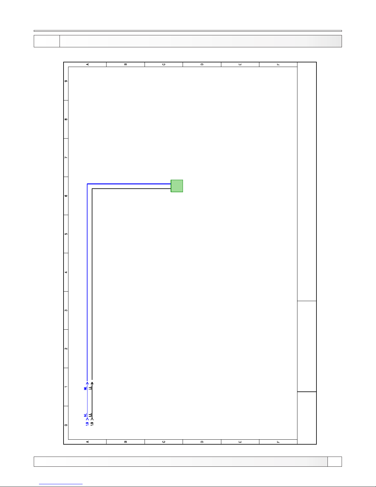
Electrical scheme (PelTec)
31
Technical instructions PelTec / PelTec-lambda
5.6.a ELECT RICA L SHE ME preparation for lambda probe (PelTec)
CENTROMETAL
PREPARATION FOR
LAMBDA PROBE BOARD
POWER SUPPLY
blue
black
S C H E M A - Control unit
PelTec
Page 32
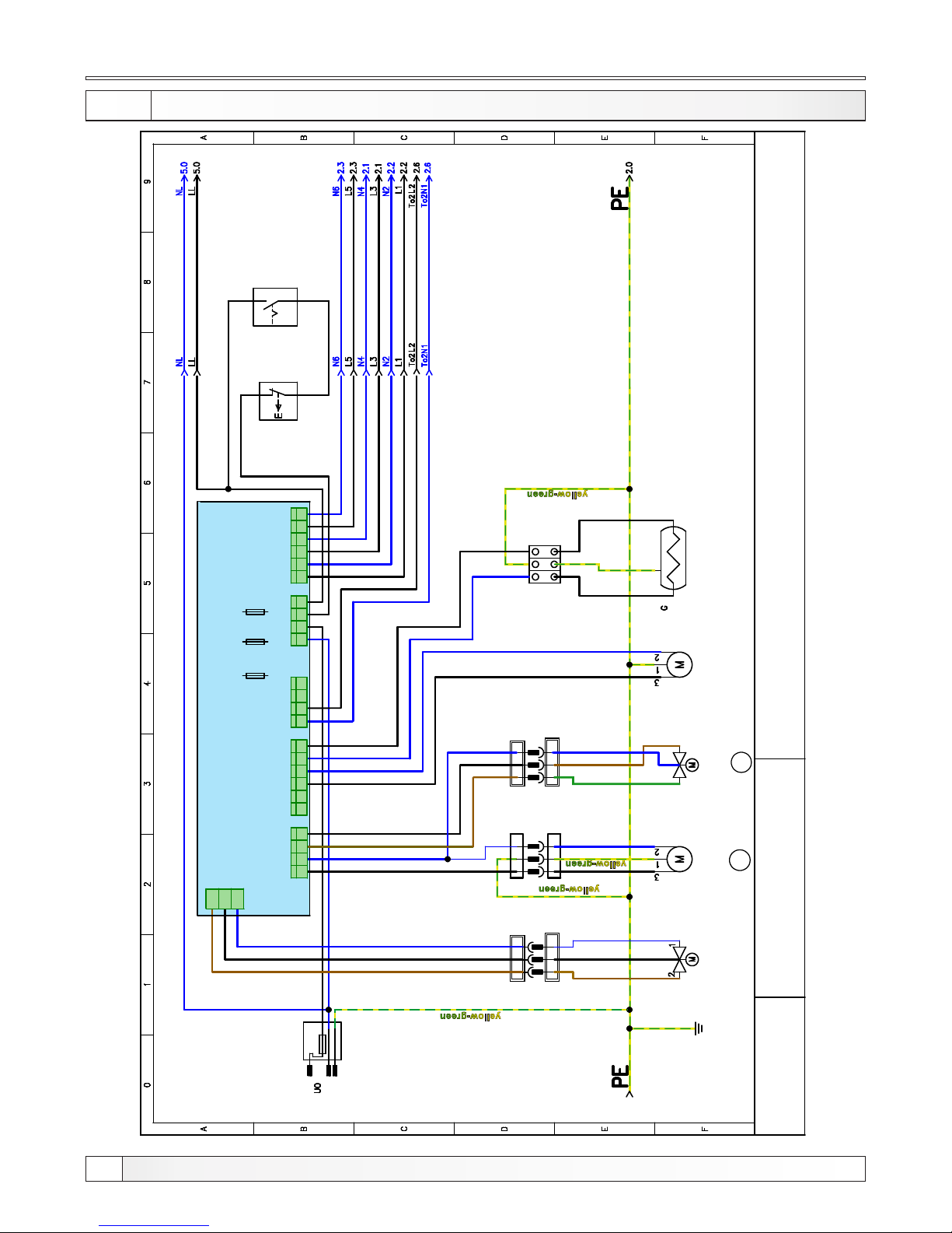
Electrical scheme (PelTec-lambda)
5.2.b ELECTRICA L SCH EME OUTPUTS 1 (PelTec-lambda)
32
Technical instructions PelTec / PelTec-lambda
CENTROMETAL
L
6, 3 A
N
PE
L1 N
3P CR NI
MUŠK I
3P CR NI
ŽENS K I
NL1
L1 N
3P BI J EL I
MUŠK I
3P BI J EL I
ŽENS K I
NL1
L1 N
L1 N
3P BI JE L I
MUŠK I
M1
M 2
S C H E M A - Control unit
PelTec-lambda
SMS motor
mechanism for
the grating
self-cleaning
PELLET
CONVEYOR
MOTOR
MIXING VALVE
ACTUATOR
FLU GAS
TUBE
CLEANING
MOTOR
ELECTRIC
HEATER
MAIN
SWITCH
SAFETY
THERMOSTAT
Connector
3-bit
white
Connector
3-bit
black
Connector
3-bit
white
Terminal
block
brown
black
blue
black
blue
black
blue
blue blue
black
blue
blue
black
black
blue
blue
black
blue
black
black
blue
black
blue
black
blue
blue
black
black
blue
brown
brown
black
green
blue
brown
PelTec-lambda
OUTPUTS
TO 1
T O 3
POW 1
L LL t L t L t L t L t L t L t L t L t L t L tN N N NN N N N NLp L p
TO 2
TO 4
1 2 3 4 1 2 3 4 5 6
1 2 3 4 1 2 3 4
1 2 3 4 5 6
L t NLt
TO 5
1 2 3
F2
fast
500mA
F3
medium
slow
3,15A
F1
fast
3,15A
Page 33
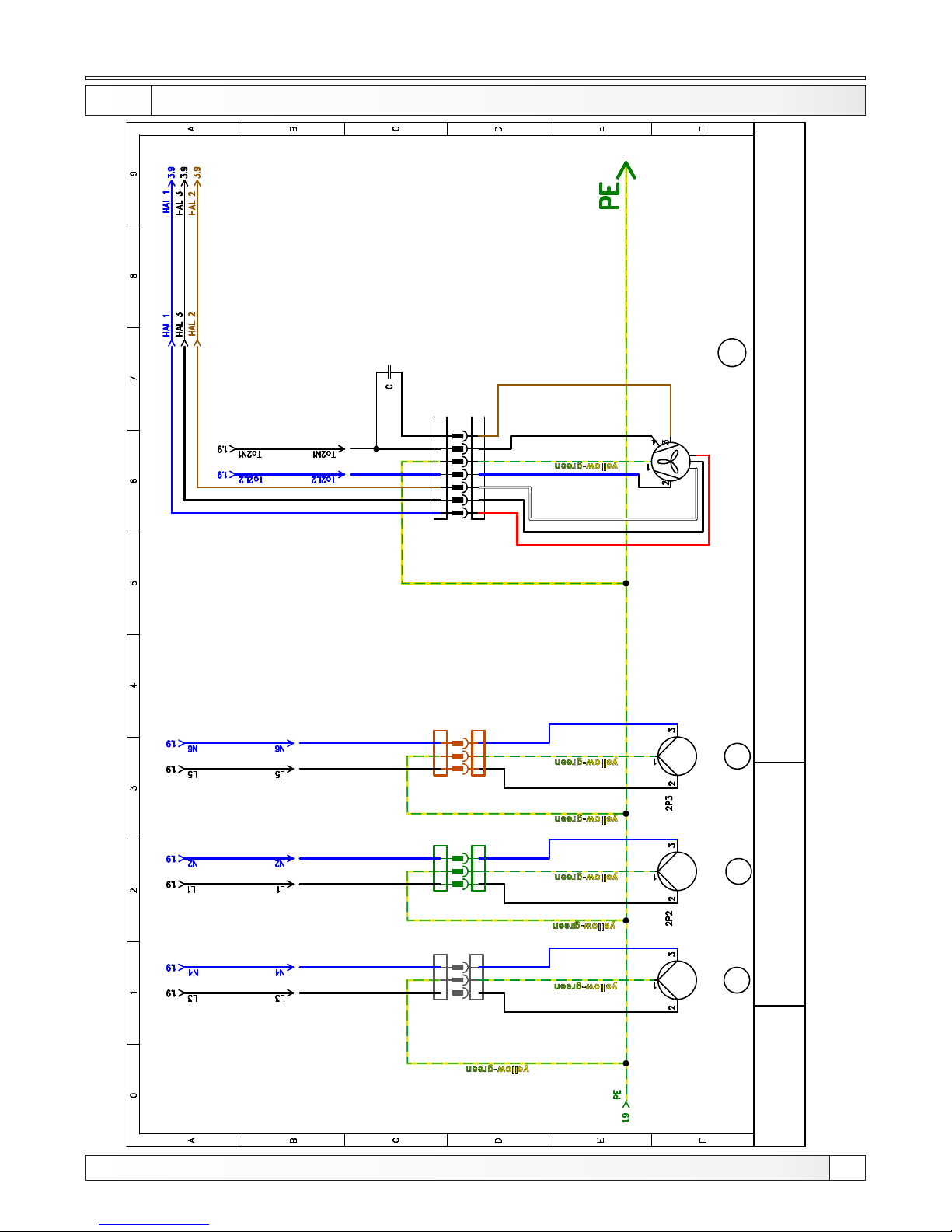
Electrical scheme (PelTec-lambda)
5.3.b ELECTRICA L SCH EME OUTPUTS 2 (PelTec-lambda)
33
Technical instructions PelTec / PelTec-lambda
CENTROMETAL
L1 N
3P SI V I
MUŠK I
3P SI V I
ŽENS K I
NL1
L1 N
3P Z EL E NI
MUŠK I
L1 N
3P SMĐEI
MUŠK I
L1 N
7P CR / SM
MUŠK I
T1 T 2 S3 B 4
7P CR / SM
ŽENS K I
NL1 T1 T 2 S 3 B 4
M 3
P1
P 2
P 3
3P SMĐEI
ŽENS K I
NL1
3P Z EL E NI
ŽENS K I
NL1
PUMP
P1
PUMP
P2
PUMP
P3
blue
black
blue
black
blue
black
Connector
3-pin
grey
black
blue
black
blue
Connector
3-pin
green
Connector
3-pin
brown
Flue gas fan with
RPM (rotates per min) sensor
black
crna
plava
blue
black
red
white
blue
black
brown
Connector
7-pin
black/brown
blue
brown
PelTec-lambda
12-24 C=2uF
PelTec-lambda
36-48 C=2,5uF
S C H E M A - Control unit
PelTec
Page 34
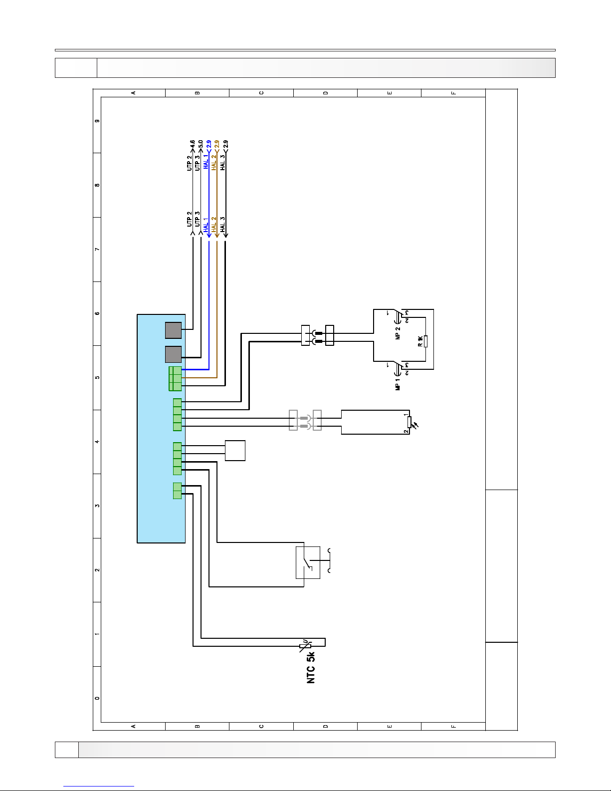
Electrical scheme (PelTec-lambda)
5.4.b ELECTRICA L SCH EME INPUTS (PelTec-lambda)
34
Technical instructions PelTec / PelTec-lambda
CENTROMETAL
PelTec-lambda INPUTS
2 1
2P SI V I
MUŠK I
2P SI V I
ŽENS K I
2 1
1
2
3
Ai 1 Ai 3 Ai 2
HAL 1
24
+5 V
SI G GND
UTP1UTP2
BOILER
SENSOR
CODE FOR
BOILER
POWER
PRESOSTAT
Photocell
blue
black
brown
Connector
2-bit
grey
1
12
3
24
1
3
1
2
3
2P C RNI
ŽENS K I
2 1
2 1
2P CR NI
MUŠK I
MICROSWITCHES
FOR MOTOR
MECHANISM
FOR THE SELF-CLEANING
Connector
2-bit
black
S C H E M A - Control unit
PelTec-lambda
Page 35
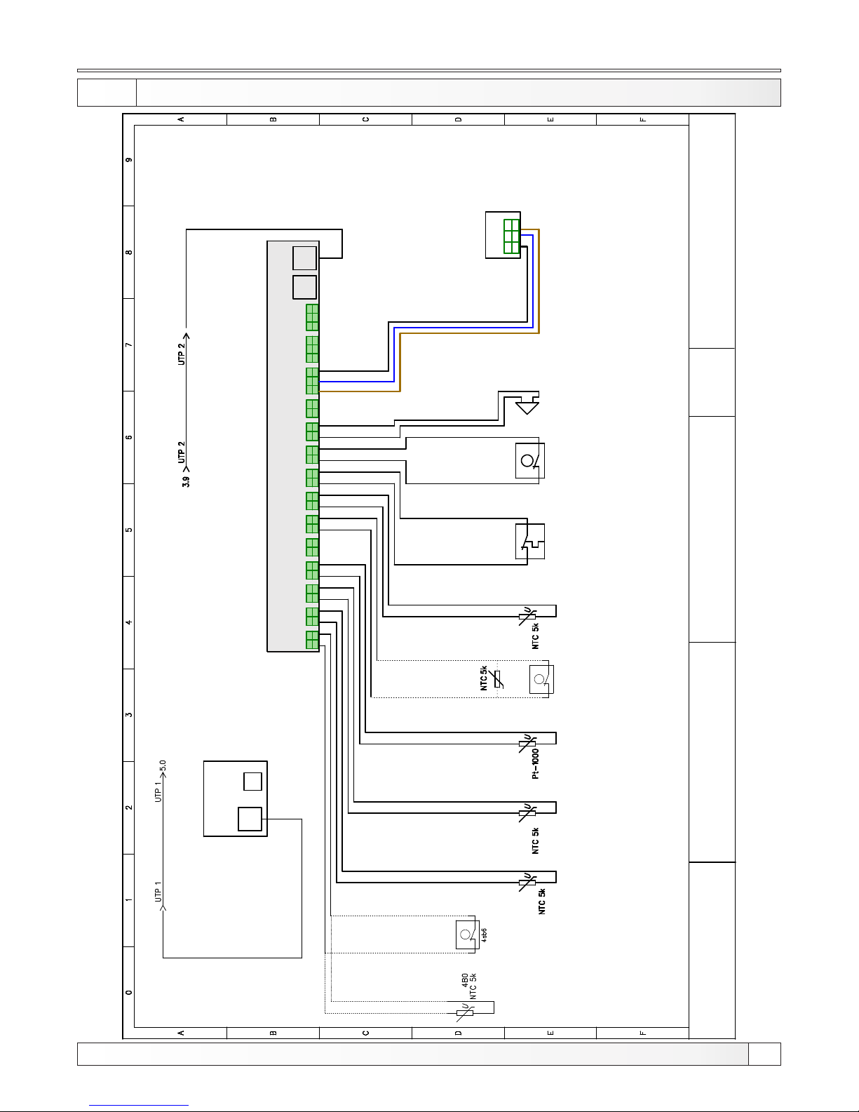
Electrical scheme (PelTec-lambda)
5.5.b ELECTRICA L SCH EME SENSORS (PelTec-lambda)
U T P
US B
U TP
1 2
SIG
GND
1 2
SIG
GND
1 2
SIG
GND
1 2
SIG
GND
1 2
SIG
GND
1 2
SIG
GND
1 2
SIG
GND
1 2
SIG
GND
1 2
SIG
GND
1 2
SIG
PelTec Display
S1 S2 S3 S4 S5 S6 S7 S8 S9
or
S1
S2
S3
S4
S7 S8
S9
SENSORS
S C H E M A - Control unit
PelTec-lambda
DHW
sensor
Depending
on the type
of installation
heating
Accumulation
tank 1 sensor
(up)
/
Hydraulic
crossover
sensor
Accumulation
tank 2 sensor
(down)
Flue
gas
sensor
Room thermostat
for second heating
circuit
Return
sensor
Bimetallic
thermostat
Room
thermostat
1. circuit /
External control
UT P
GND
1 2
SIG
GND
1 2
SIG
GND
1 2
+5 V
3
GND
SIG
UT P 1 U T P 2
1 2
+5V
3
GND
SIG
1 2
+5V
3
GND
SIG
3 2
+5 V
1
GND
SIG
S10 S11 S12 S13 S14
blue
black
brown
Alarm sound
max. 100 mA
(12V)
S10
S12
PELLET LEVEL IN
THE TANK SENSOR
4 / 5
35
Technical instructions PelTec / PelTec-lambda
The flow
sensor /
External
control
S6
Depending
on the type
of installation
heating
or
Page 36
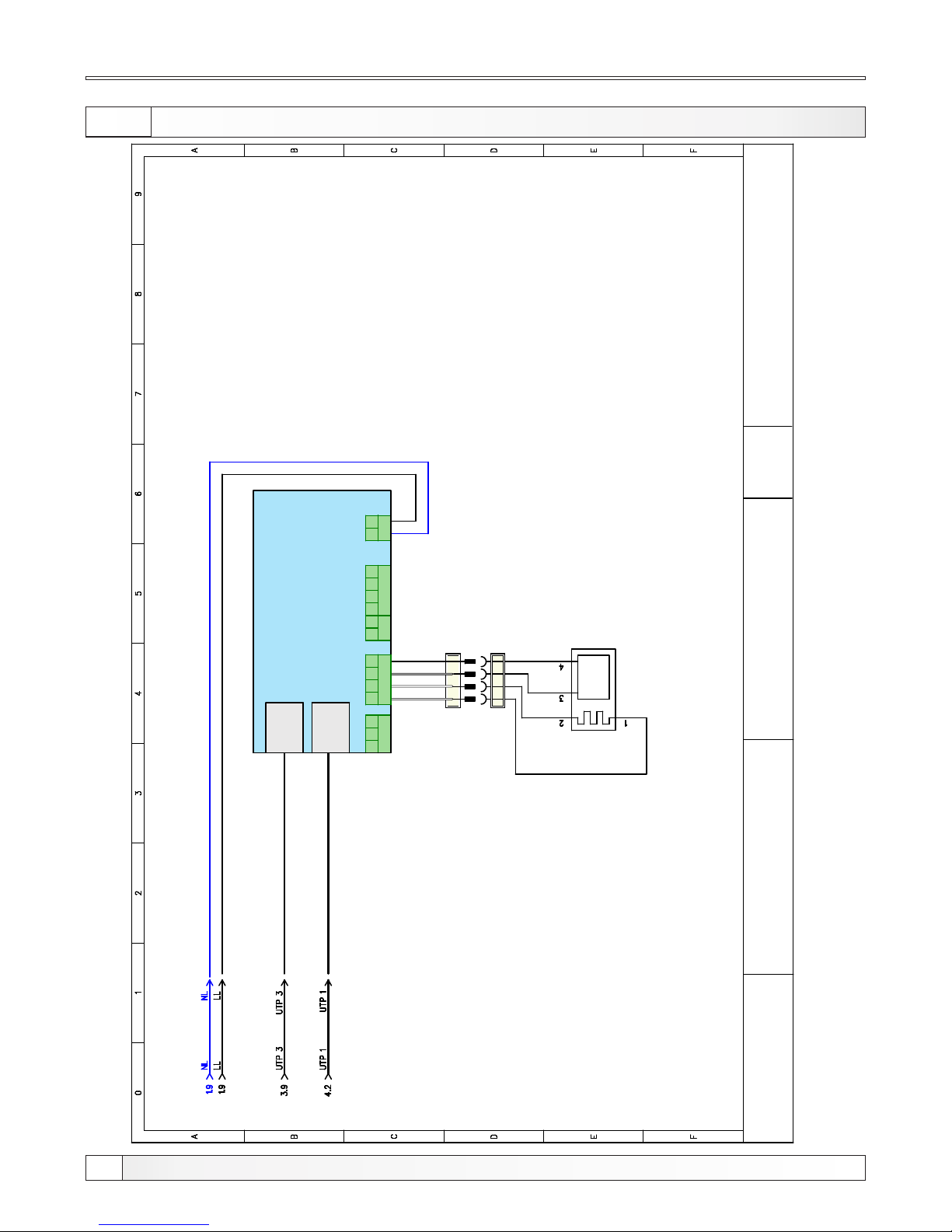
Elektrical sheme (PelTec-lambda)
5.6.b ELECTRICA L SHE ME L AMBDA PROBE (PelTec-lambda)
»
H
H
+
_
UT P
UT P
RS 4 85
A
B G
T f g. S
1
2
DI / AO
G
S T
O
N F
23 0 V
1
1
8
8
blue
UTP 1
UTP 2
Lambda
board
Lambda probe
L AMB D A S E NZ O R
H
H
L-
L+
white
white
grey
black
blue
S C H E M A - Control unit
PelTec-lambda
5 / 5
36
Technical instructions PelTec / PelTec-lambda
Page 37
Operating the system, safety, startup
6.0. OPERATING THE SYSTEM
6.1. SAFETY INSTRUCTIONS F OR T HE INSTA LLATI ON ROOM
Boiler must not be used in flammable and explosive environment.
It must not be used by children or disabled persons (either physically or mentally), as well as by person
without knowledge or experience, unless they are under control or trained by s person responsible for
their safety.
Children must be supervised in the vicinity of the product. If the supply cord is damaged, it must be
replaced by the manufacturer, its service agent or similarly qualified.
Boiler room must be frost-proof and well ventilated. Boiler has to be positioned so that it can be properly
connected to the chimney (see point 4.0) and simultaneously, enabling tending of boiler and additional
equipment, control during operation, and cleaning and maintenance
6.2. INITIAL STARTUP
See technical instructions for PelTec / PelTec-lambda digital control unit where is explained initial
startup.
Note:
The start up has to be done by the authorized person, otherwise the warranty for this product is not valid
and the product must not be used.
Note:
If condensation escapes during the initial heatup phase, this does not indicate a fault.
If this occurs, clean up using a cleaning rag.
6.3. FILLING / R EFILLING PELLET TANK WITH FUEL
CAUTION:
Use only permitted pellets!
37
Technical instructions PelTec / PelTec-lambda
Page 38
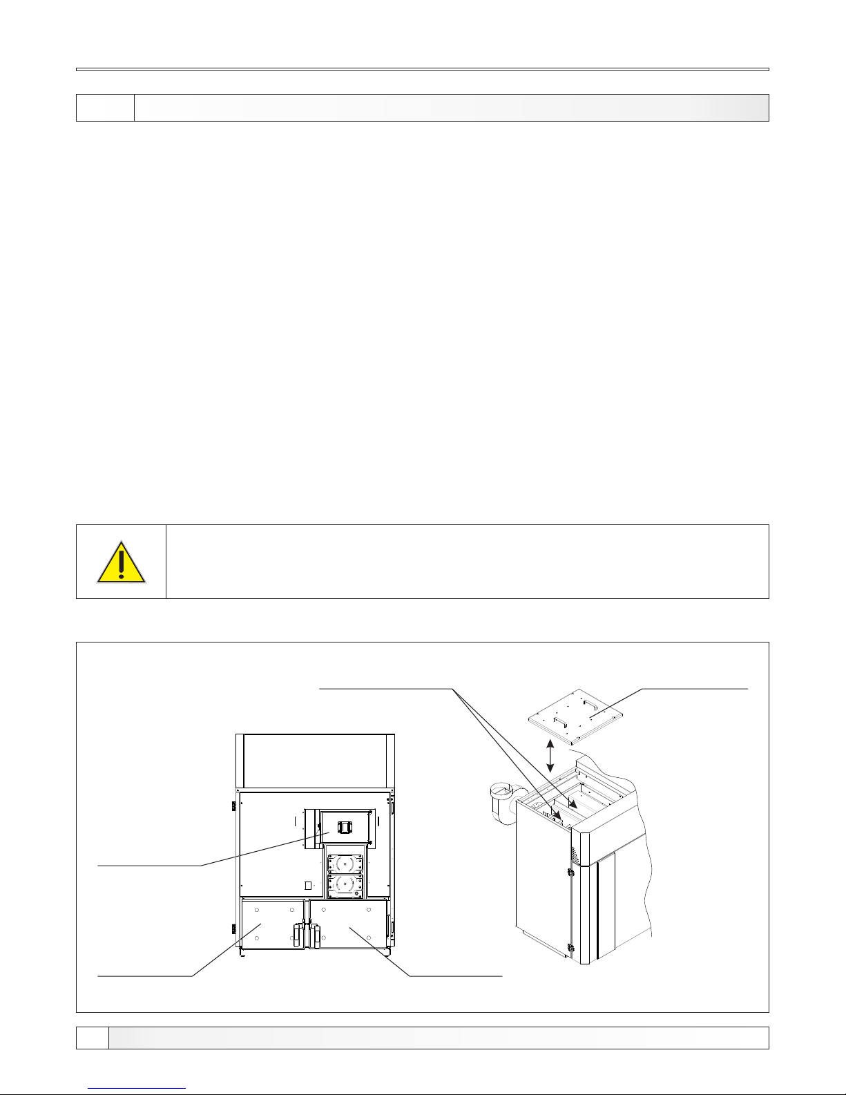
If you smell flue gas:
- shut down the heating system
- Ventilate the boiler room
- Close all doors leading to the living space
6.3. BOILER USE
Boiler must not be used in flammable and explosive environment.
It must not be used by children or disabled persons (either physically or mentally), as well as by person
without knowledge or experience, unless they are under control or trained by s person responsible for
their safety. Children must be supervised in the vicinity of the product. If the supply cord is damaged, it
must be replaced by the manufacturer, its service agent or similarly qualified persons in order to avoid a
hazard. Protective gloves are obligatory.
Check whether boiler and equipment are installed and connected in accordance with these Technical
instructions. Check whether chimney meets requirements of point 3.0 therein. Check whether boiler
room meets all requirements therein. Check if fuel fulfils all requirements therein. Check whether the
boiler and the entire heating system are filled with water and vented.
Note:
Before every use chech if the boiler doors and cover door are closed (Figure 4).
Slika 9. PelTec / PelTec-lambda boiler door
Left low boiler
door
(Behind the door is a box of ashes)
Upper boiler
door
Flue gas can lead to life-threating poisoning!
Boiler use
Flue gas tubes
door
Right low boiler
door
(Behind the door is a box of ashes)
Turbulators of flue gas
tubes
38
Technical instructions PelTec / PelTec-lambda
Page 39
Cleaning and maintenance
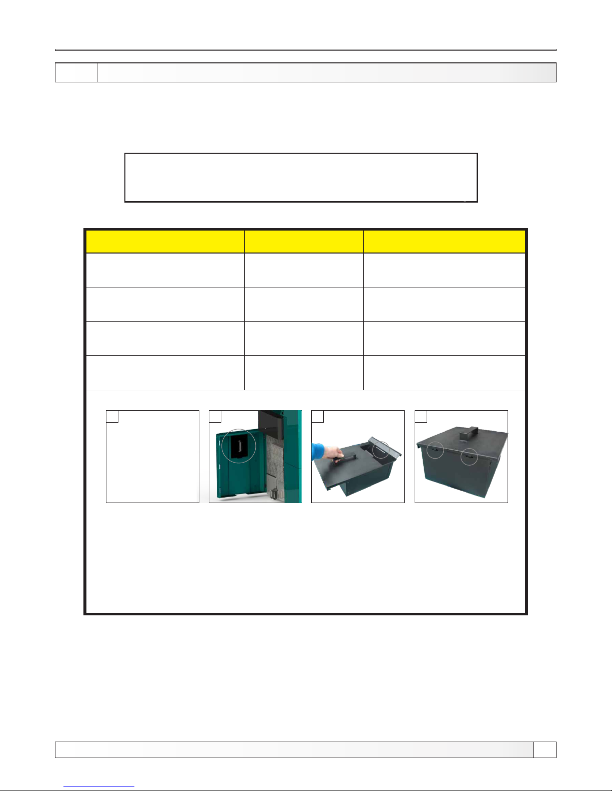
7.0. CLEANING AN D MAINTENANCE
Every millimeter of soot on the exchange surfaces and in the flues means about 5 % more fuel
consumption. A clean boiler saves fuel and protects the environment.
Save fuel – always clean the boiler in good time!
IMPORTANT! The ash can be disposed of only in a metal container!
Cleaning interval
Boiler type Description
After spent 150-250 kg
of pellets
12kW
Discharge ash boxes
After spent 250-350 kg
of pellets
18kW
After spent 300-450 kg
of pellets
24kW
After spent 400-600 kg
of pellets
36-48kW
Emptying the ash box:
2 3 41
1. Take out ash boxes.
2. For carrying ash boxes, use a protective cover which is located on the inside of front
door. For boilers 18,24, 36 and 48 kW take out one by one box in order to
use the same cover (Figure 2).
3. Attach the cover to the 3 holes (Figure 3.4) .
4. Put the cover and ash box back to original position.
PROTECTIVE GLOVES ARE OBLIGATORY!!
Discharge ash boxes
Discharge ash boxes
Discharge ash boxes
39
Technical instructions PelTec / PelTec-lambda
Page 40
Cleaning intervals
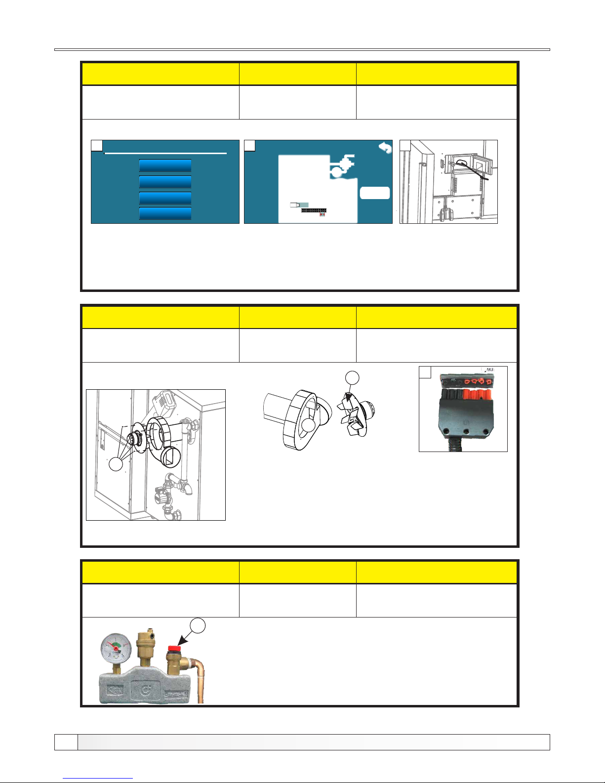
Checking the correctness of security valve
By briefly turning the cap of safety valve (C) check whether water coming
out from the safety valve. If no water comes out after several repeated
checks, then is necessary to replace the safety valve.
Cleaning interval
Boiler type Description
When needed
12-48 kW
Cleaning the blades and box of
the fan
Cleaning the blades and box of the fan
Cleaning interval Boiler type Description
Every 6 months
12-48 kW
Check the correctness of security
valve
A
C
V
3
Cleaning interval
Boiler type Description
At least once per year
(This procedure is very simple and is
recommends even more often)
12-48 kW
Cleaning of exchanging surfaces
(above the burner)
Claning of exchanging surfaces (above the burner)
1 - Press the ''maintenance'' on the regulation and then ''Boiler Cleaning''.
2 - Press ''START'' (it will start the fan and it will open a grate.)
3 - By using scraper, brush or vacuum cleaner, through the door clean exchanging surfaces
4 - After you finish cleaning, press ''back'' ( ) on regulation to control the boiler back to normal mode
and close the front door of the boiler.
1. Maintenance
Man. Boiler Cleaning
1.
2.
3.
Filling feeder screw
Airvent
Man. Boiler Cleaning
0%
2000
15k
1 2
1. Switch off the boiler and disconnect from electric. power.
2. Pull out the 7 pin connector (Figure 6) from boiler control unit. Then
unscrew four screws (V) and remove the fan, clean the fan blades (A),
check the condition of the fan box (B) and clean it when is necessary
by using vacuum cleaner or remove it from the boiler and clean
thoroughly.
3. Set back the fan into original position and secure it with screws,
then connect 7-pin connector on the M3 (see page 24, figure 5) and
connect the power supply to the boiler.
B
6
3.
Weighing
40
Technical instructions PelTec / PelTec-lambda
Page 41
Cleaning intervals
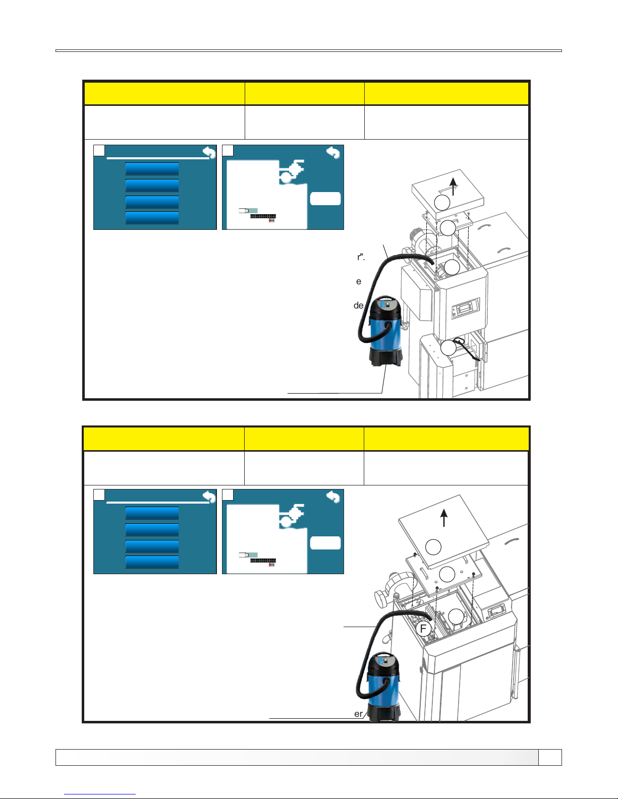
Cleaning interval Boiler type Description
At least once per year
12 kW
Cleaning of exchanging surfaces
(around the entire boiler)
1. Press ''Maintenance'' on the regulation and then ''Cleaning the boiler''.
2. Press ''START'' (it will start the fan and it will open a grate.)
3. Lift the top cover (D), then unscrew the four screws and remove the
upper door (E).
4. By using scraper, brush and vacuum cleaner, through the upper side
and trough the front door clean exchanging surfaces(F,G).
5. When you have finished cleaning, set upper door back to
original position and tighten them well, then set the top cover
back to position and close the front door of the boiler. Then press
''back'' on the regulation ( ) to return boiler to normal
mode.
1. Maintenance
Man. Boiler Cleaning
0%
2000
15k
1 2
Metal vacuum cleaner
E
D
F
G
F
G
Cleaning interval Boiler type Description
At least once per year
18-48 kW
Cleaning of exchanging surfaces
(around the entire boiler)
1. Press ''Maintenance'' on the regulation and then ''Cleaning the boiler''.
2. Press ''START'' (it will start the fan and it will open a grate.)
3. Lift the top cover (D), then unscrew the four screws
and remove the upper door (E).
4. By using scraper, brush and vacuum cleaner, through
the upper side clean exchanging surfaces(F,G).
5. When you have finished cleaning, set upper door back to
original position and tighten them well, then set the top cover
back to position. Then press ''back'' on the regulation ( ) to
return boiler to normal mode.
Metal vacuum cleaner
D
E
18-48 kW
F
G
12 kW
Man. Boiler Cleaning
1.
2.
3.
Filling feeder screw
Airvent
3.
Weighing
1. Maintenance
Man. Boiler Cleaning
0%
2000
15k
1 2
Man. Boiler Cleaning
1.
2.
3.
Filling feeder screw
Airvent
3.
Weighing
Metal
tube
Metal
tube
41
Technical instructions PelTec / PelTec-lambda
Page 42
Cleaning intervals
Cleaning interval
Boiler type Description
At least once per year
12-48 kW
Cleaning and checking the
flue installation sealing
Clean flue installation between the boiler and the chimney through the revision openings
for cleaning or if not incorporated revision opened by removing the flue installation. After
cleaning, inspect flue installation good sealing and seal it if the seal is not satisfactory.
Cleaning and checking the flue installation sealing
The ecological rules and standards must be applied for disposal of
changed spare parts, wrapping material, all parts of the boiler after it’s
expire.
1. Electric heater
2. Failure on distribution power box with digital boiler control unit
3. Fan failure
4. Pellet feeder Motor failure
5. Temperature sensors failure
6. Photocell failure
Every seven years to call an authorized service provider for routine maintenance and
control.
Cleaning interval
Boiler type Description
At least once a year
(or if you have problems
with the ignition)
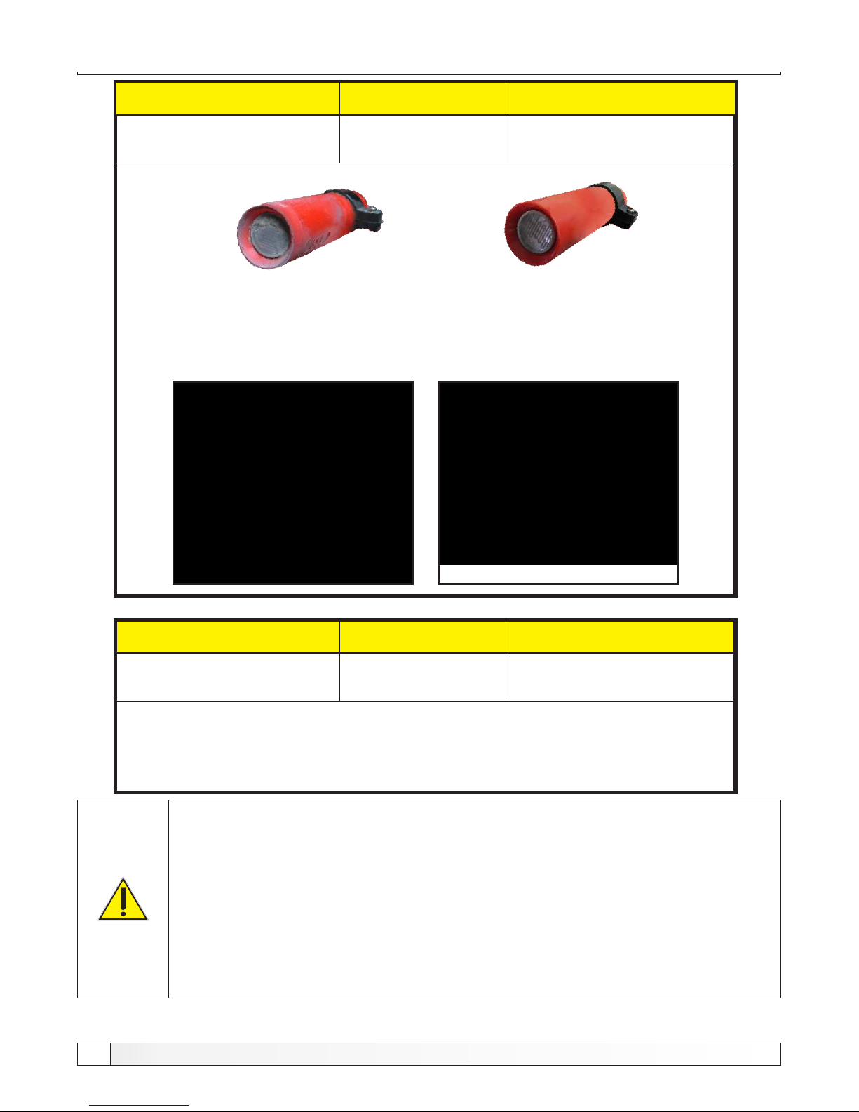
18-48 kW
Photocell cleaning
Dirty photocell which can result
error in ignition or flame dissapear
error
Valid photocell
Carefully remove the photocell from the box and then gently with a cotton swab clean the body
and lens of photocell. After cleaning, carefully return photocell to work position.
Work position
42
Technical instructions PelTec / PelTec-lambda
Page 43
Cleaning and maintenance
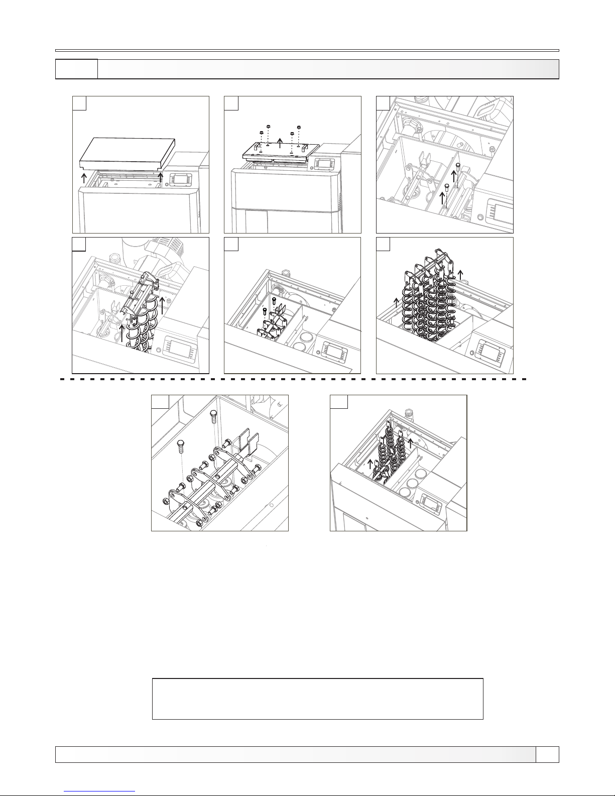
7.1. EXTRACTION O F TU RBULATORS
NOTE:
Place turbulators back in the same way but in the reverse order!
There are 1 or 2 sets of turbulators (depending on the model of boiler)
PROTECTIVE GLOVES ARE OBLIGATORY!
1 - Remove the casing cover.
2 - Unscrew the 4 srews and remove the flue ducts door.
3,4 - Unscrew the 2 srews and lift turbulators (first pass) with bracket as shown in picture.
5 - Unscrew the 2 srews from carrier on second pass.
6 - Remove all turbulators with carrier. (If you can’t remove all turbulators together, then
unscrew all screws on all turbulators (6.a) and remove turbulators one by one (6b).
4
1
2
3
5
6
6.a
6.a i 6.b Samo u slučaju da nije moguće odjednom izvaditi sve turbulatore (korak 6)
6.b
43
Technical instructions PelTec / PelTec-lambda
Page 44
7.2. EXTRACTION OF HELICAL METAL PLATE FROM SECOND PASS
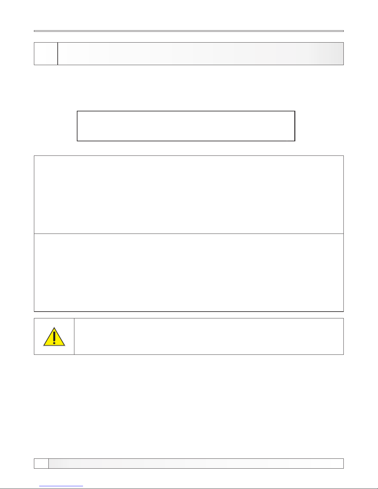
TURBULATORS
For extracting of helical metal plate from turbulators is neccessary to unscrew nut and pull out helical
metal plate from the bottom. With this action the flue gas temperature (in boiler work) will be increased
but if there si no other solution for chimney condensation prevention (reduction to acceptable level)
that procedure is neccessary.
Turbulatior with helial metal plate
Extracted helical metal plate
This procedure should do only authorized serviceman!
Extraction of helical metal plate from second pass turbulators
PROTECTIVE GLOVES ARE OBLIGATORY!!
44
Technical instructions PelTec / PelTec-lambda
Page 45
7.3 REPLACEMENT OF THE ELECTRIC HEATER
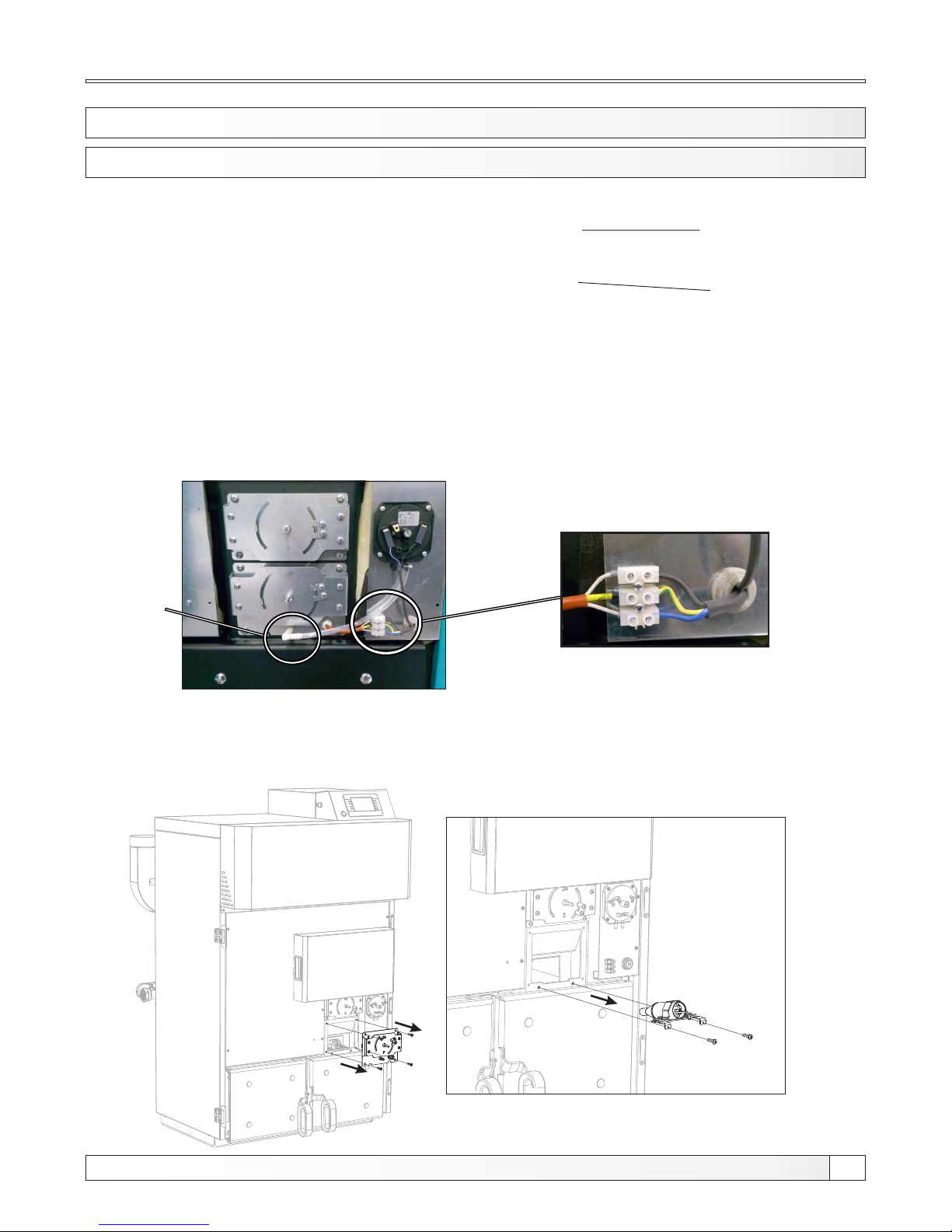
7.3.1 REPLACEMENT OF THE EL.HEATER WITH NEW EL. HEATER DIAMETER Ø35mm
Replacement of the electric heater
Electric heater with a diameter of Ø 35 mm
1. Unplug the safety pressure switch tube (detail A), and disconnect the wires of the electric heater
from the terminal block (Detail B).
2. Unscrew the 4 screws and remove the primary air regulation. Then unscrew the 2 heater holder screw
and pull out heaters holder together with the el. heater.
The heater holder
(Heater holder is identical with
heaters diameter Ø20mm and
Ø35mm)
Heater clamp for heater
diameter Ø35mm
The heater holder with clamp for electric heater with
a diameter of Ø35 mm
45
Technical instructions PelTec / PelTec-lambda
Detail A
Detail B
Page 46
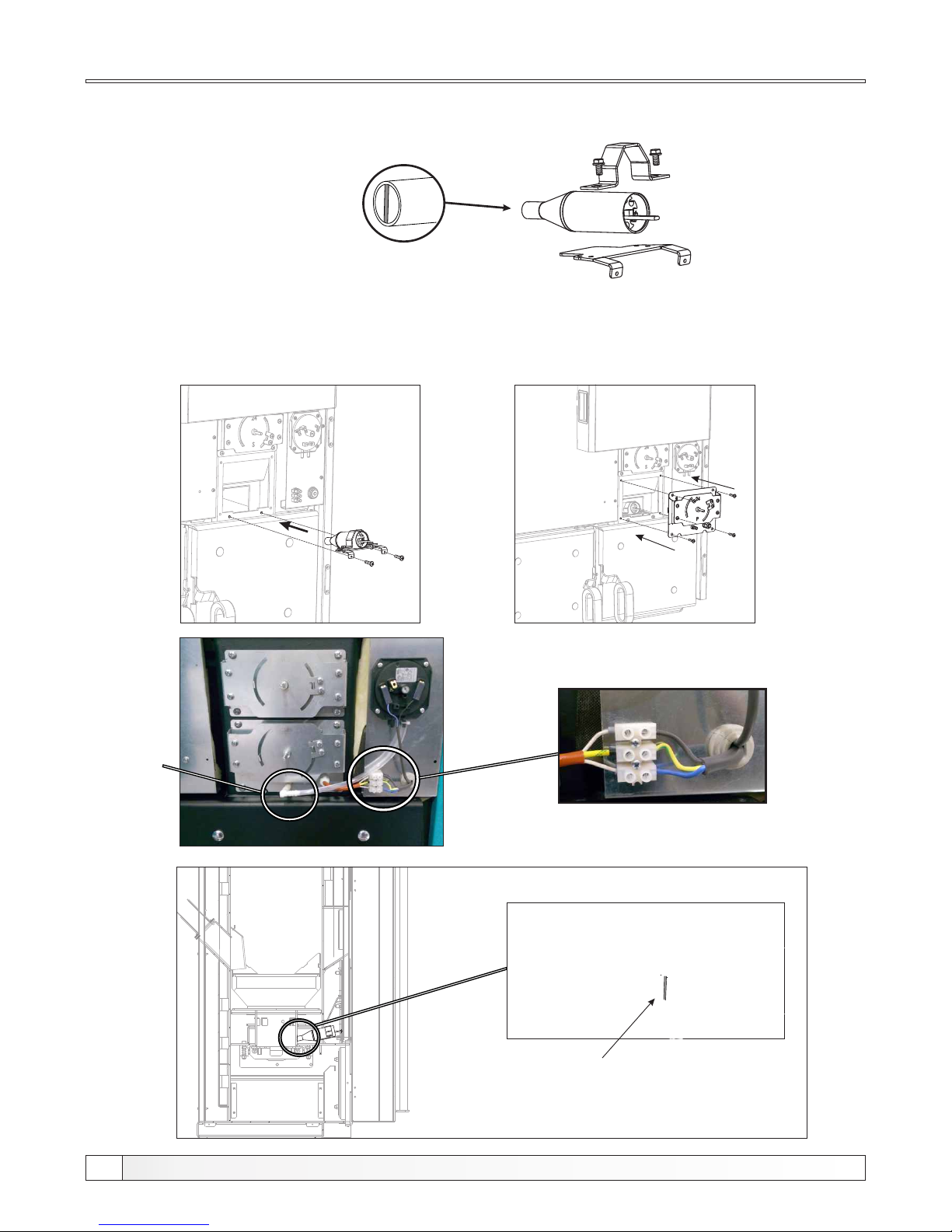
Replacement of the electric heater
3. Unscrew the two screws and remove the heater clamp. Insert the new el. heater, turn it so that
the shaft at the front part of the el heater is turned vertically (see detail C) and gently attach it
to the heater holder (Still not fully tightened).
4. Place the el. heater with the holder in place and fasten it with two screws. The heater set to the inner
edge of the hole burner (see detail D). If necessary, loosen the clamp of the heater holder and push the
holder until the edge of the burner hole and then tighten the clamp. Place the primary air regulation and
connect with 4 screws. Connect the el. heater wires to the terminal block (detail B) and connect pressure
switch tube (detail A).
(Shaft at the front part of the
el. heater is turned vertically)
Detail C
Detail D
To the inner edge of the burner hole.
46
Technical instructions PelTec / PelTec-lambda
Detail A
Detail B
Page 47
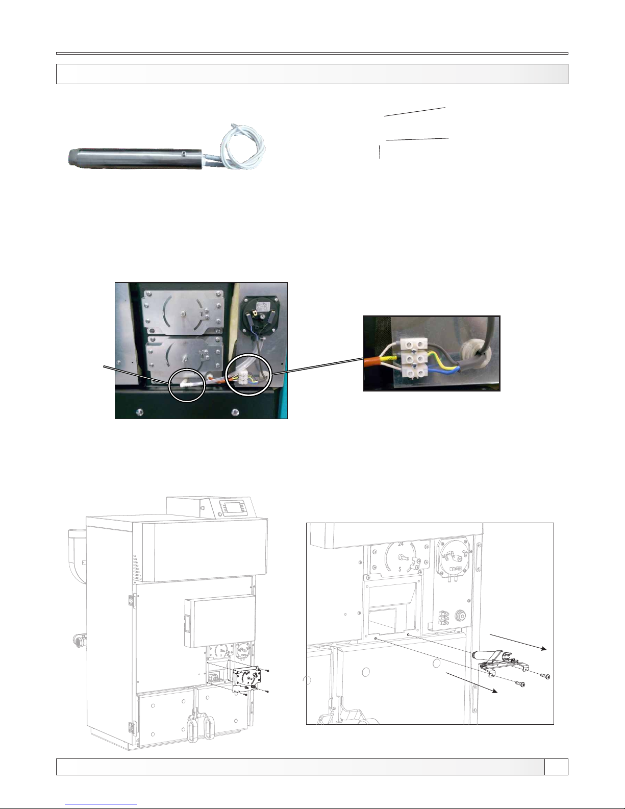
The heater holder with clamp for electric
heater with a diameter of Ø 20 mm
The upper part of the heater
clamp diameter Ø20mm
The lower part of the heater
clamp diameter Ø20mm
Replacement of the electric heater
7.3.2 REPLACEMENT OF THE EL.HEATER WITH NEW EL. HEATER DIAMETER Ø20mm
Electric heater with a diameter of Ø 20 mm
The heater holder
(Heater holder is identical with
heaters diameter Ø20mm and
Ø35mm)
1. Unplug the safety pressure switch tube (detail A), and disconnect the wires of the electric heater
from the terminal block (Detail B).
2. Unscrew the 4 screws and remove the primary air regulation. Then unscrew the 2 heater holder screw
and pull out heaters holder together with the el. heater.
47
Technical instructions PelTec / PelTec-lambda
Detail A
Detail B
Page 48
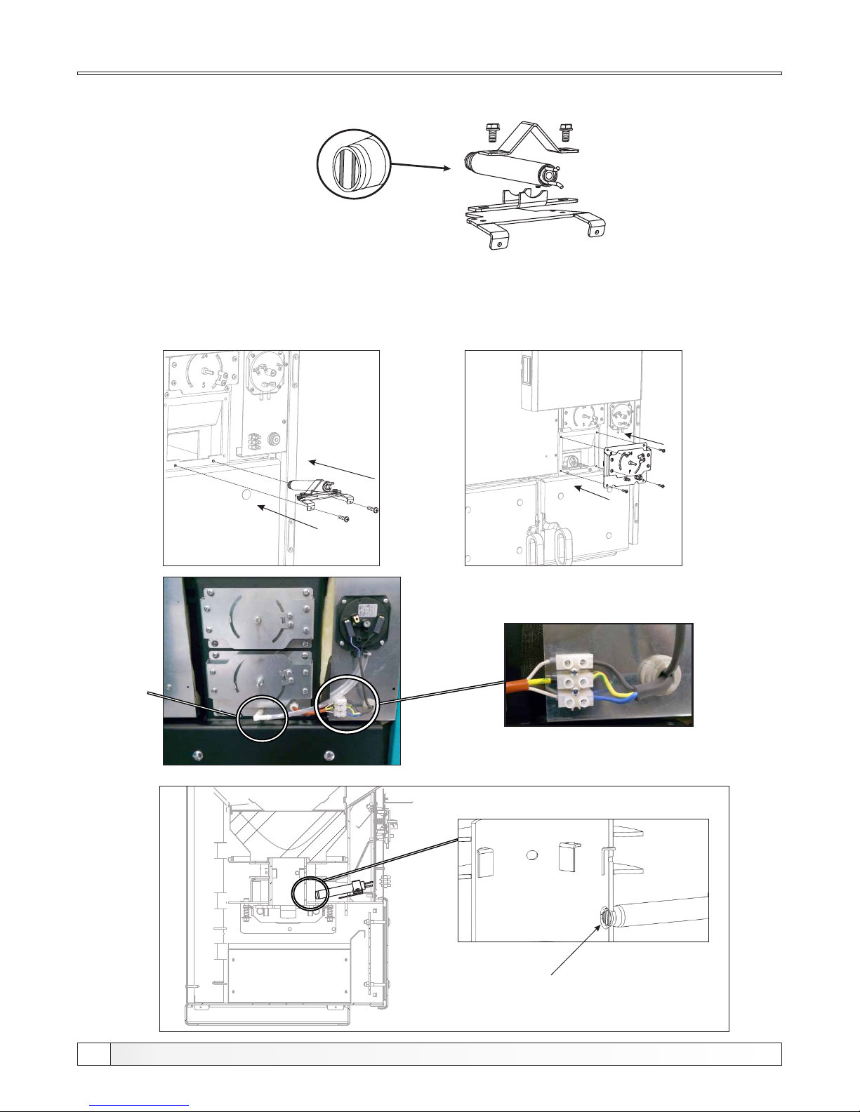
(Shafts at the front part
of the el. heater are
turned vertically)
Detail C
3. Unscrew the two screws and remove the heater clamp. Insert the new el. heater, turn it so that
the shafts at the front part of the el heater are turned vertically (see detail C) and gently attach
it to the heater holder (Still not fully tightened).
Replacement of the electric heater
Detail D
To the inner edge of the burner hole.
4. Place the el. heater with the holder in place and fasten it with two screws. Set the heater to the inner
edge of the hole burner (see detail D). If necessary, loosen the clamp of the heater holder and push the
holder until the edge of the burner hole and then tighten the clamp. Place the primary air regulation and
connect with 4 screws. Connect the el. heater wires to the terminal block (detail B) and connect pressure
switch tube (detail A).
48
Technical instructions PelTec / PelTec-lambda
Detail A
Detail B
Page 49

49
Technical instructions PelTec / PelTec-lambda
Page 50
HEATING TECHNIQUE
www.centrometal.hr
e-mail: [email protected]
Centrometal d.o.o. Glavna 12, 40306 Macinec, Croatia
central tel: +385 40 372 600, fax: +385 40 372 611
service tel: +385 40 372 622, fax: +385 40 372 621
Company assumes no responsibility for possible inaccuracies in this book originated typographical errors or rewriting, all the pictures and diagrams are principal and it is necessary to adjust each actual situation
on the field, in any case the company reserves the right to enter their own products such modifications as considered necessary.
TUPLT/PLT-L-10-2017-sms-pg-ENG
 Loading...