

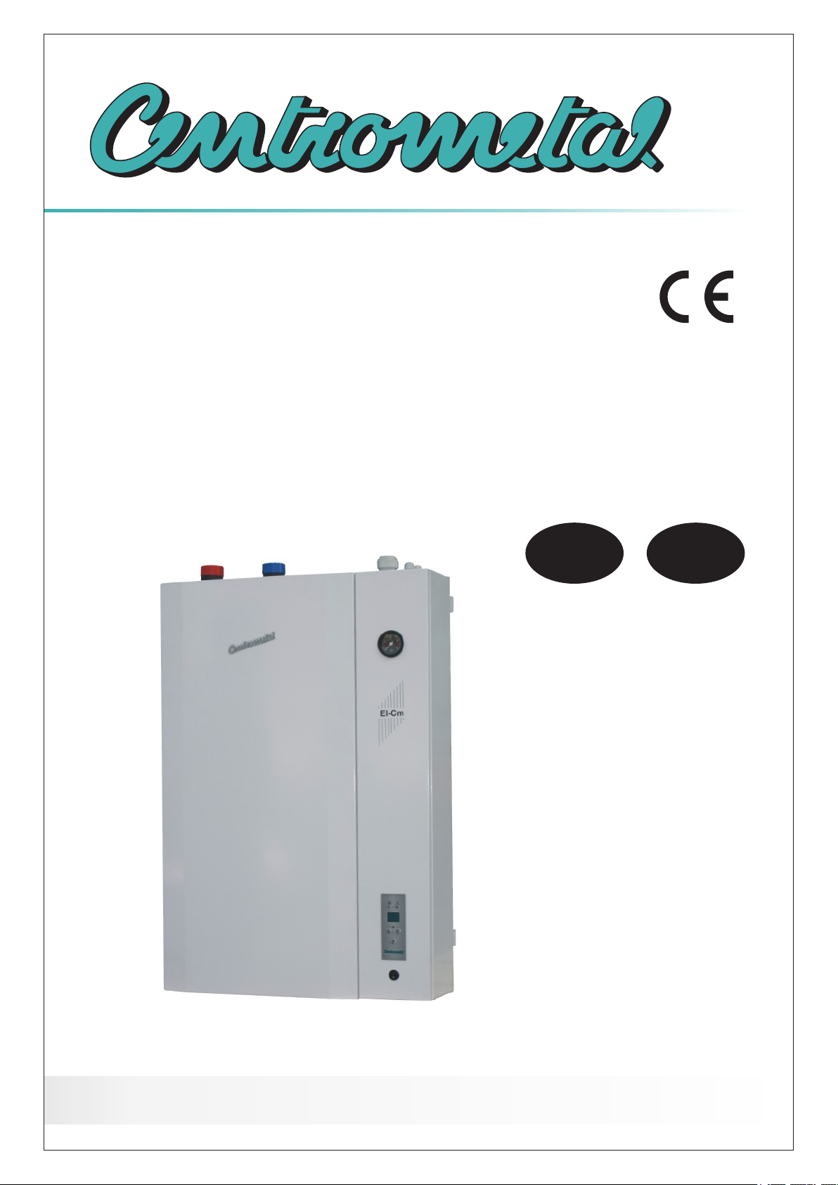
Centrometal El-Cm Series, El-Cm 30, El-Cm 33, El-Cm 39, El-Cm 42 Technical Manual [en, hr]
...Page 1
HEATING TECHNIQUE
Centrometal d.o.o. - Glavna 12, 40306 Macinec, Croatia, tel: 040 372 600, fax: 040 372 611
TEHNIČKO UPUTSTVO / TECHICAL MANUAL
za montažu, upotrebu i održavanjetoplovodnog elektrokotla te za montažu dodatne opreme /
for assembling, use and maintenance of the electric boiler and additional equipment
HR
EN
TUELCM-08/2017
El-Cm
Page 2
HR
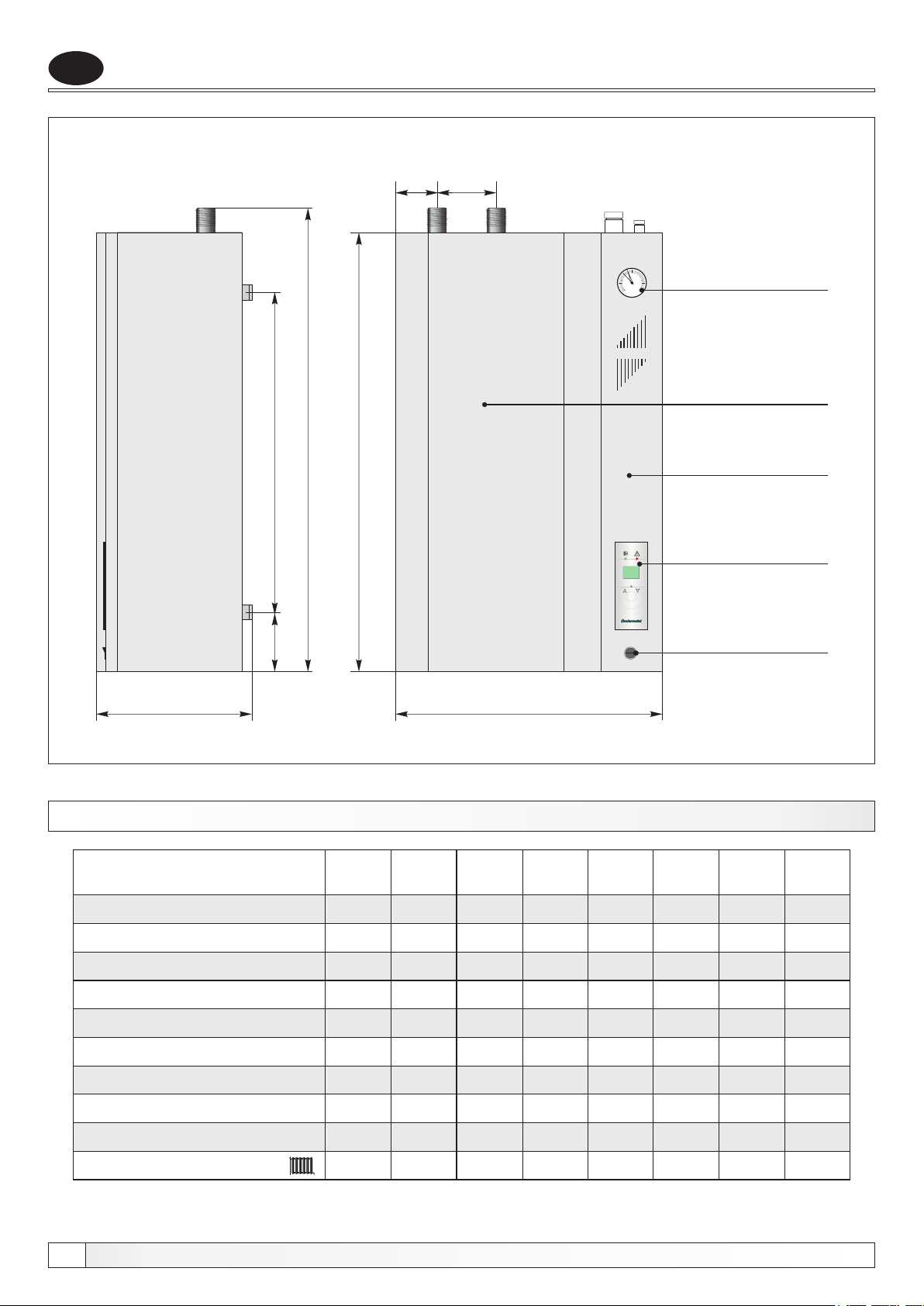
Slika 1. - Osnovne dimenzije elektro kotla El-Cm
15585
935
735
910
2
1
0
bar
El-Cm
Tehnički podaci
3
4
Prednji poklopac
(može se skinuti,
Konzola regulacije
(može se otvoriti,
Manometar
odvrnuti 4 vijka)
odvinuti 2 vijka)
205
TEHNIČKI PODACI
El-Cm
Toplinski učin
Volumen kotl. vode
Masa kotla
Max. radni pretlak
Max. radni pretlak
Električni grijač
Presjek vodiča
Polazni/Povratni vod
Otpor kotla na vodenoj strani
115
(kW)
(lit.)
(kg)
(bar)
(MPa)
(kW)
(mm )
(R)
(mbar)
2
30
22
44
2,5
0,25
3x9+3
5x10
6/4"
8
33
33
22
44
2,5
0,25
3x9+6
5x10
6/4"
9
64
P
TEHNIKA GRIJANJA
1
0
630
36 4239 45
36
22
44
2,5
0,25
4x9
5x16
6/4"
12,5
39
22
45
2,5
0,25
3x12+3
5x16
6/4"
15
42
22
45
2,5
0,25
3x12+6
5x25
6/4"
17,5
0,25
3x12+9
5x25
6/4"
Digitalna
modulirajuća
kotlovska
regulacija
Glavna sklopka
4830
45
22
45
2,5
19
48
22
45
2,5
0,25
4x12
5x25
6/4"
23
51
51
22
45
2,5
0,25
4x12,75
5x25
6/4"
25
Razred energetske učinkovitosti
2
C C C C C C C C
Tehničko uputstvo El-Cm
Page 3
Osnovni dijelovi
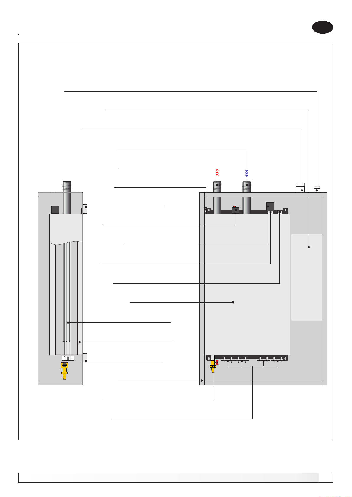
Slika 2. - Dijelovi elektro kotla El-Cm
Uvodnica za sobni termostat i cirk. pumpu
Regulacijska kutija
Uvodnica za priključno napajanje
Povratni vod
Polazni vod
Mikroprekidač
HR
Nosač kotla
Sigurnosni termostat
Presostat
Sonda za manometar
Sonda za ticala
Kotao
Električni grijač
Toplinska izolacija
Nosač kotla
Tehničko uputstvo El-Cm
Oplata kotla
Punjenje/pražnjenje
Električni grijači
3
Page 4
HR
Opis kotla
1.0. OPĆENITO
Toplovodni kotao El-Cm suvremene je konstrukcije i dizajna, izrađen iz atestiranih materijala
visoke kvalitete, varen najsuvremenijom tehnologijom zavarivanja, ispitan i atestiran po
hrvatskim i europskim normama te ispunjava sve uvjete za priključenje na instalaciju centralnog
grijanja. Preporučamo Vam da slijedite naše upute sa pozornošću, kako bi Vaš kotao El-Cm
mogao duže i pravilnije raditi.
Tvrtka Centrometal d.o.o. ne preuzima odgovornost za moguće netočnosti u ovoj brošuri, nastale
tiskanim greškama ili prepisivanjem, u svakom slučaju pridržava si pravo unositi vlastitim
proizvodima one izmjene koje smatra potrebnim i korisnim bez prethodne najave.
2.0. NAMJENA
Serija elektro kotlova El-Cm projektirana je za grijanje kuća ili stanova sa toplinskim učinkom od
30 do 51 kW kao samostalni izvor energije. Modernog je dizajna, minimalnih dimenzija te se može
montirati u razne dijelove stana ili kuće.
3.0. SASTAVNI DIJELOVI KOTLA El-Cm
KOTAO
Izrađen je iz kvalitetnog kotlovskog lima, varen najmodernijom tehnologijom zavarivanja, ispitan
tlakom od 0,6 MPa (6 bar-a) te izvana zaštićen kvalitetnom temeljnom bojom.
GLAVNA SKLOPKA
Glavna sklopka uključuje/isključuje el. napajanje kotla.
PREDNJI POKLOPAC
Prednji poklopac pričvršćen je za oplatu pomoću 4 vijka (2 sa gornje i 2 sa donje strane kotla).
Skidanjem prednjeg poklopca dolazi se do glavnih dijelova kotla i aktivira se mikro prekidač koji
isključuje rad regulacije, ali ne prekida dovod el. struje u kotao.
POLAZNI VOD
Cijev polaznog voda (6/4") označena je crvenom naljepnicom i nalazi se na gornjoj lijevoj strani
kotla.
POVRATNI VOD
Cijev povratnog voda (6/4") označena je plavom naljepnicom, nalazi se na gornjoj desnoj strani
kotla i provučena je do dna kotla tako da raspršuje ohlađenu povratnu vodu jednakomjerno po
kotlu te jednakomjerno oplahuje el. grijače.
SONDA ZA TICALA
Na gornjoj strani tijela kotla nalazi se sonda za ticalo kotlovske regulacije.
SIGURNOSNI TERMOSTAT
Nalježni sigurnosni termostat nalazi se na gornjoj strani tijela kotla, uz tlačnu sklopku, kada je
aktiviran isključuje napajanje kotla.
4
Tehničko uputstvo El-Cm
Page 5
Sastavni dijelovi kotla
ELEKTRIČNI GRIJAČI
El. grijači ugrađeni su sa donje strane kotla, snage ovisne o ukupno potrebnoj maksimalnoj snazi
kotla.
TERMOIZOLACIJSKI SLOJ
Elektro kotao El-Cm izoliran je termoizolacijskim slojem mineralne vune, odgovarajuće gustoće,
debljine 30 mm na Al-foliji, koja smanjuje gubitak topline konvekcijom i zračenjem.
PUNJENJE/PRAŽNJENJE
Na donjoj strani tijela kotla, zabrtvljena je slavina za punjenje/pražnjenje kotla i sistema.
TLAČNA SKLOPKA (PRESOSTAT)
U slučaju pada tlaka tlačna sklopka isključuje rad regulacije da bi se spriječio rad kotla bez vode,
ali ne prekida dovod el. struje u kotao.
MIKRO PREKIDAČ
U slučaju otvaranja prednjeg poklopca kotla mikro prekidač isključuje rad regulacije, ali ne
prekida dovod el. struje u kotao.
HR
KOTLOVSKA REGULACIJA
Modulirajuća digitalna regulacija upravlja radom el. grijača i nalazi se na konzoli regulacije sa
desne strane kotla.
Tehničko uputstvo El-Cm
5
Page 6
HR
Montaža kotla
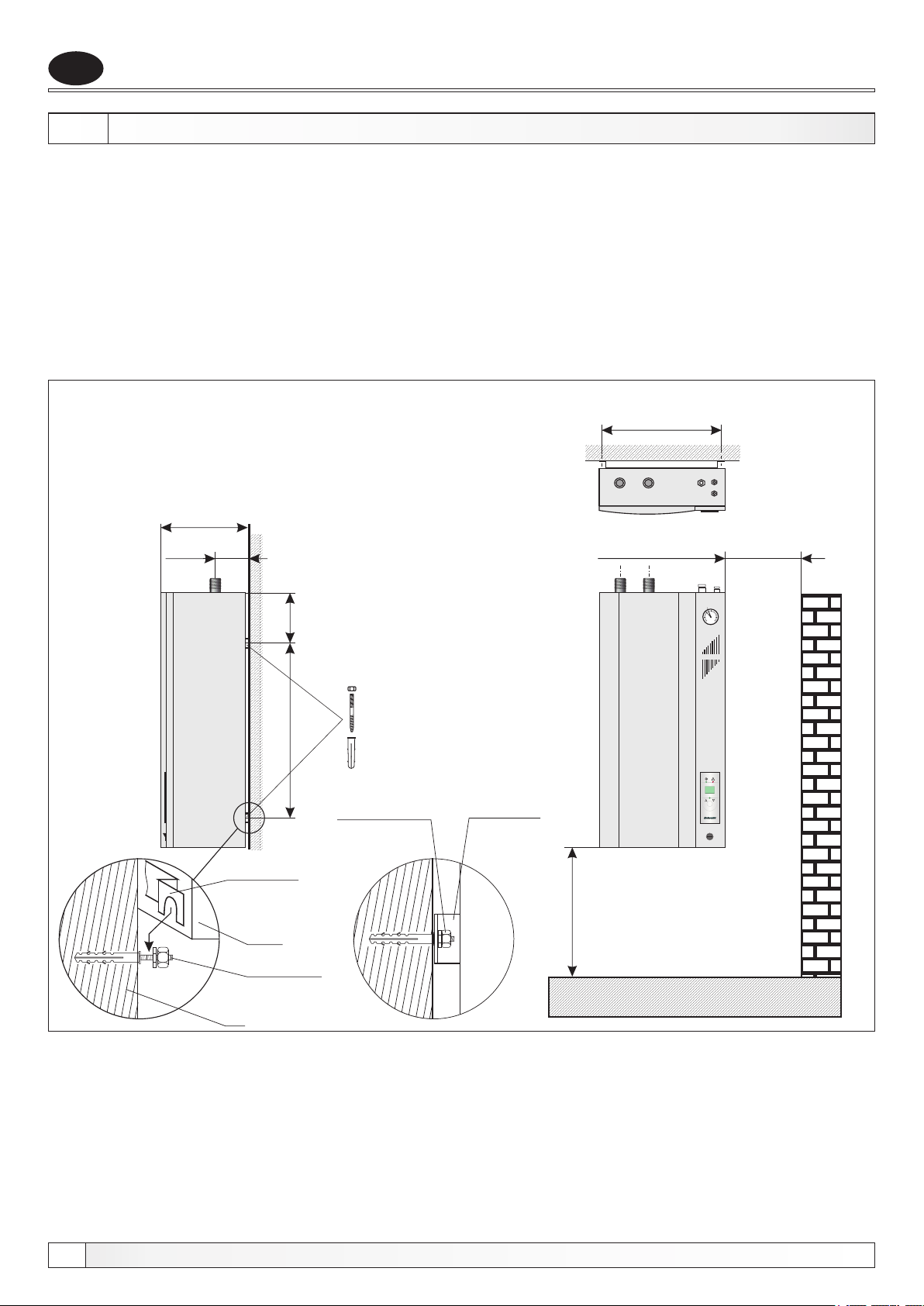
4.0. MONTAŽA KOTLA
Elektro kotao El-Cm predviđen je za montažu na zid za koju ima na stražnjoj strani predviđene
konzole za ovješenje. Za ovješenje se mogu upotrijebiti metalni zidni ulošci (tiple) sa vijkom M10
ili jači plastični zidni ulošci. Kotao mora biti montiran najmanje 0,6 m od poda radi eventualne
zamjene el. grijača, odnosno odmaknut od bočnog zida sa desne strane kotla 0,3 m, radi lakšeg
pristupa kotlu. Kotao treba po mogućnosti montirati na najnižu točku u odnosu na instalaciju.
Ukoliko ga zbog nedostatka prostora treba instalirati na najvišu točku, potrebno je na njegov
izlazni dio postaviti odzračnu posudu sa minimalnom količinom vode (cca. 1 lit.) i na tu posudu
montirati automatski odzračni lončić. Preporučamo da montažu kotla obavi stručna osoba.
Slika 3. - Montaža elektro kotla El-Cm na zid
600
100
205
60
735
Nosač kotla
(na stražnjoj
strani kotla)
Kotao
Hangar vijak
Nakon stavljanja
kotla na nosače
pričvrstiti matice
Nosač kotla
(na stražnjoj
strani kotla)
min. 300 mm
min. 600 mm
1
El-Cm
64
2
3
0
4
bar
P
TEHNIKA GRIJANJA
1
0
Zid
6
Tehničko uputstvo El-Cm
Page 7
Priključenje na instalaciju grijanja
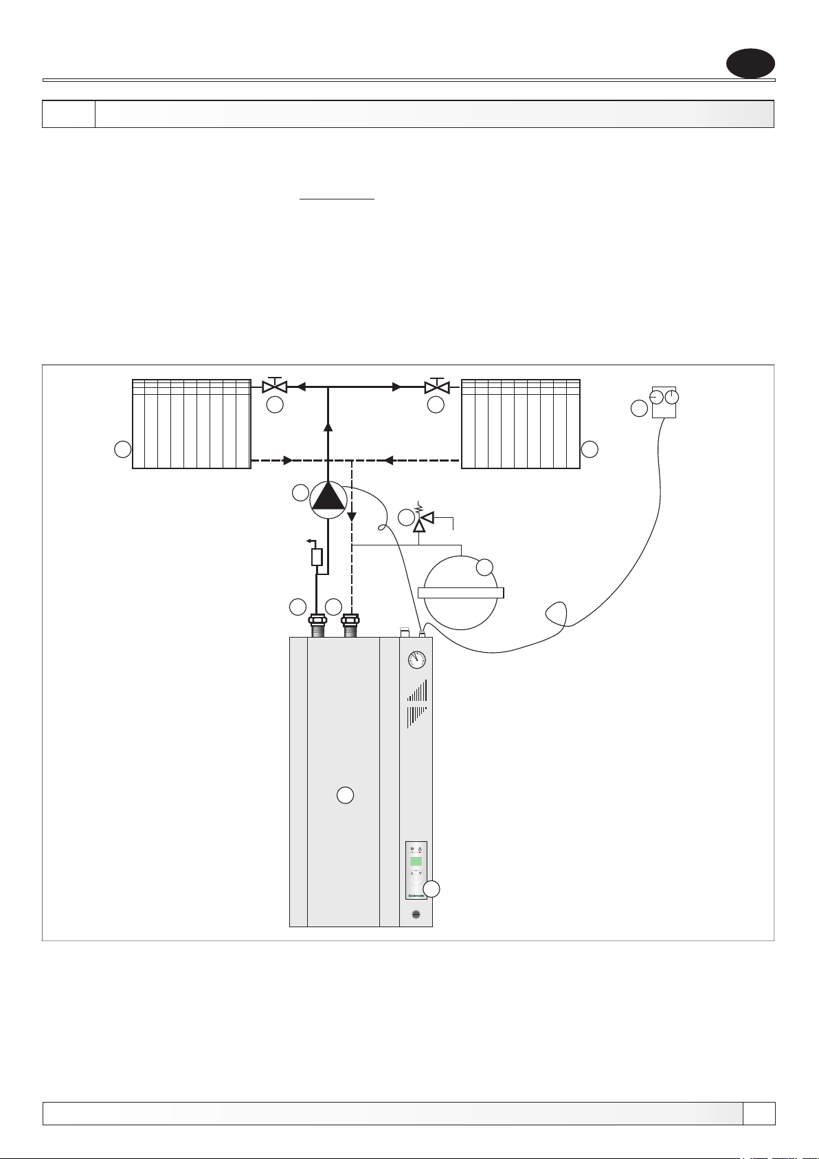
5.0. PRIKLJUČENJE KOTLA El-Cm NA INSTALACIJU GRIJANJA
Priključenje na cijevnu instalaciju sustava grijanja i puštanje u pogon kotla, mora se izvesti prema
važećim tehničkim normama, od strane stručne osobe, koja preuzima odgovornost.
Kod zatvorenog sustava grijanja obavezna je ugradnja atestiranog sigurnosnog ventila s tlakom
otvaranja 0,25 MPa (2,5 bar-a) i membranske ekspanzijske posude. Sigurnosni ventil i
ekspanzijska posuda moraju biti ugrađeni prema pravilima struke te ne smije biti nikakvog
zapornog elementa između sigurnosnog ventila odnosno ekspanzijske posude i kotla.
Ovi su kotlovi namijenjeni za ugradnju u zatvorene sustave grijanja (ne ugrađuju se na otvorene
sustave grijanja).
Pumpa sustava može biti ugrađena na polazni (preporuka) ili povratni vod kotla.
Ovisno o prostoru koji želimo zagrijavati, njegovoj namjeni i toplinskim gubicima odabiremo
ispravnu snagu kotla.
HR
4
3
Slika 4. - Načelna shema
spajanja elektro kotla El-Cm
4
6
3
9
8
7
5
5
2
3
1
0
4
bar
1. Elektro kotao El-Cm
El-Cm
2. Digitalna kotlovska regulacija
3. Radijator
4. Ventil
1
5. Rastavljivi (holender) spoj
6. Sobni termostat
na instalaciju grijanja
Tehničko uputstvo El-Cm
7. Ekspanzijska posuda
64
P
2
1
0
8. Sigurnosni ventil (2,5 bar)
9. Cirkulacijska pumpa
7
Page 8
HR
Elektro priključak, regulacija
6.0. ELEKTRO PRIKLJUČAK
Sve elektro radove treba izvesti prema važećim propisima i od strane ovlaštene osobe.
Kompletna elektro instalacija kotla izvedena je tvornički. Sva dodatna spajanja (napajanje kotla,
cirkulacijska pumpa grijanja, sobni termostat) vrše se na rednoj stezaljci kotla. Cirkulacijsku
pumpu grijanja spojiti na rednu stezaljku na regulaciji na stezaljke br. 3, N i PE.
Napajanje kotla izvodimo PGP vodičem, odgovarajućeg presjeka kroz uvodnicu označenu
oznakama (L ) (L ) (L ) (N) (PE).
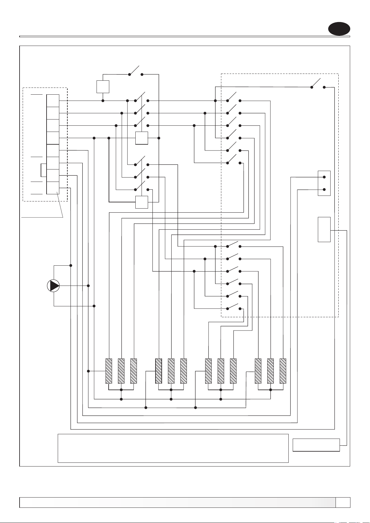
Električna shema prikazana je na Shemi 1.
Uvodnice koje se ne koriste moraju biti vodonepropusno zatvorene.
Priprema za prekid svih polova od električnog napona mreže mora biti ugrađena u električnoj
instalaciji u skladu sa državnim instalacijskim propisima.
Kotao nije namijenjen za upotrebu osobama (uključujući djecu) sa smanjenim fizičkim, osjetilnim
ili mentalnim sposobnostima ili sa nedostatkom iskustva i znanja, osim ako su pod nadzorom ili
poučeni glede upotrebe od strane osobe zaduženje za njihovu sigurnost.
Djeca moraju biti pod nadzorom da se osigura da se ne igraju sa kotlom.
Ne uključivati kotao ako postoji vjerojatnost da je voda u kotlu smrznuta.
1 2 3
6.1. SIGURNOSNI TERMOSTAT
Sigurnosni termostat montiran je na gornjoj strani kotla. Sigurnosni termostat prekida rad kotla
ukoliko temperatura u kotlu postigne 95°C. Za ponovno puštanje kotla u rad, potrebno je pričekati
da temperatura u kotlu padne ispod 70°C te tada skinuti poklopac kotla koji je pričvršćen pomoću
4 vijka (2 sa gornje i 2 sa donje strane) i pritisnuti crveno tipkalo na sigurnosnom termostatu.
Ukoliko dolazi do učestalih prekida u radu kotla pozvati stručnjaka radi kontrole.
6.2. PRIKLJUČENJE SOBNOG TERMOSTATA
Elektro kotlovi El-Cm imaju predviđene stezaljke (1) i (2) za spajanje sobnog termostata.
Tvornički je na stezaljkama (1) i (2) postavljen kratkospojnik (brika) za slučajeve kada se sobni
termostat ne koristi, a ukoliko ga spajamo moramo voditi računa o tome koja vrsta sobnog
termostata se priključuje. Jednostavnije izvedbe sobnog termostata spajaju se serijski u krug
komandnog napona, odnosno na stezaljke (1) - napajanje sobnog termostata, a povrat faze na
stezaljku (2). Kvalitetniji sobni termostati sa signalnom lampicom ili ugrađenim sistemom
simulacije temperature koji moraju biti stalno pod naponom, spajaju se na stezaljke (1) i (2).
8
Tehničko uputstvo El-Cm
Page 9
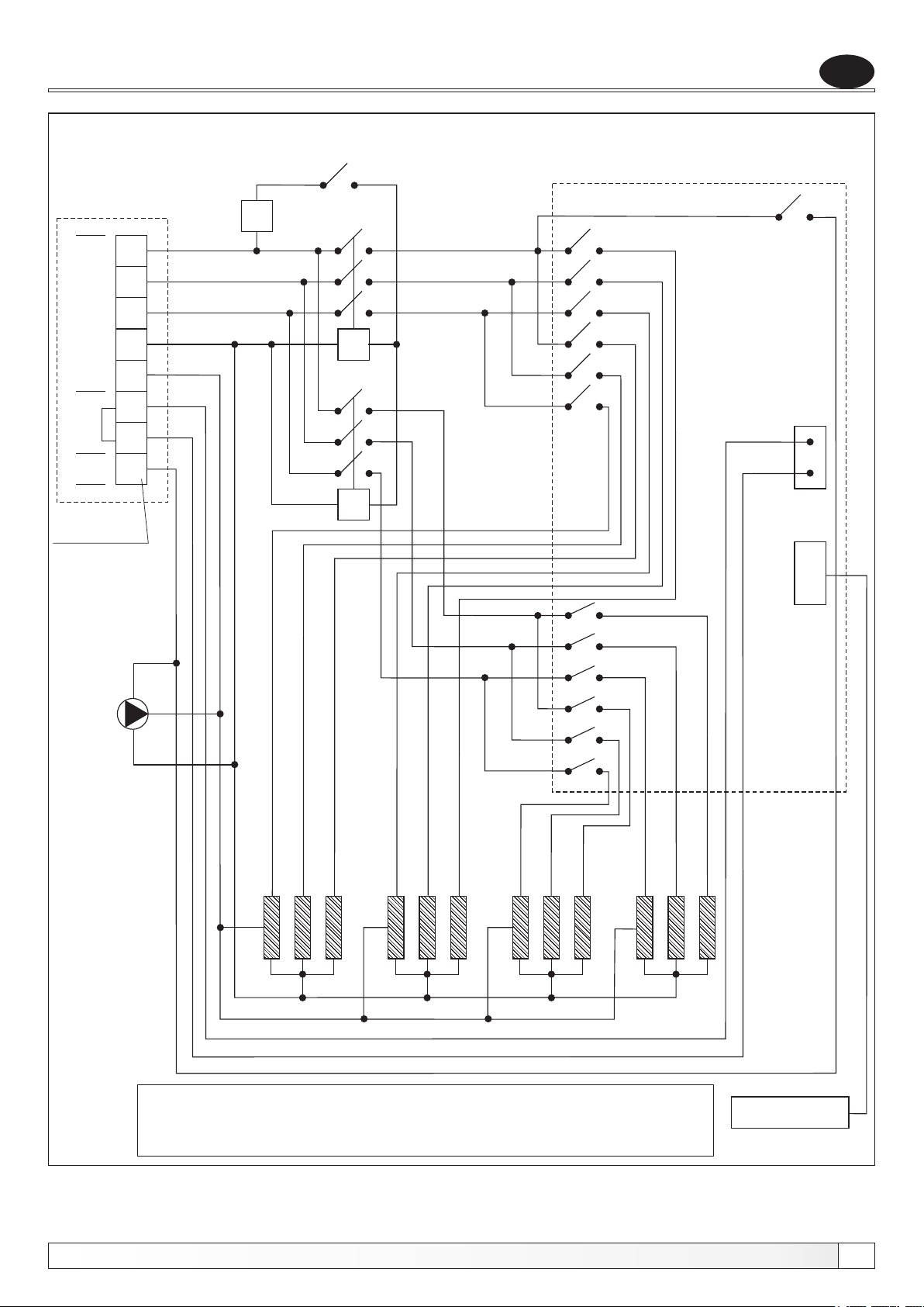
Električna shema
Shema 1. - El. shema elektro kotla El-Cm 30 - 51 kW (3-fazni priključak)
RE
REGULACIJSKA
PLOČA
L
L
Priključni
L
1
2
3
napon 3 x 400V
ST
P
HR
N
PE
termostat
Sobni
1
2
Pumpa
Redna stezaljka
3
K
K
1
EG EG EG EG EG EG
LEGENDA:
P - glavni prekidač
ST - sigurnosni termostat
K - kontaktor
Tehničko uputstvo El-Cm
EG EG EG EG EG
K - kontaktor 1
1
EG
EG - elektro-grijač
RE - regulacijska elektronika
LED-DISPLAY
9
Page 10
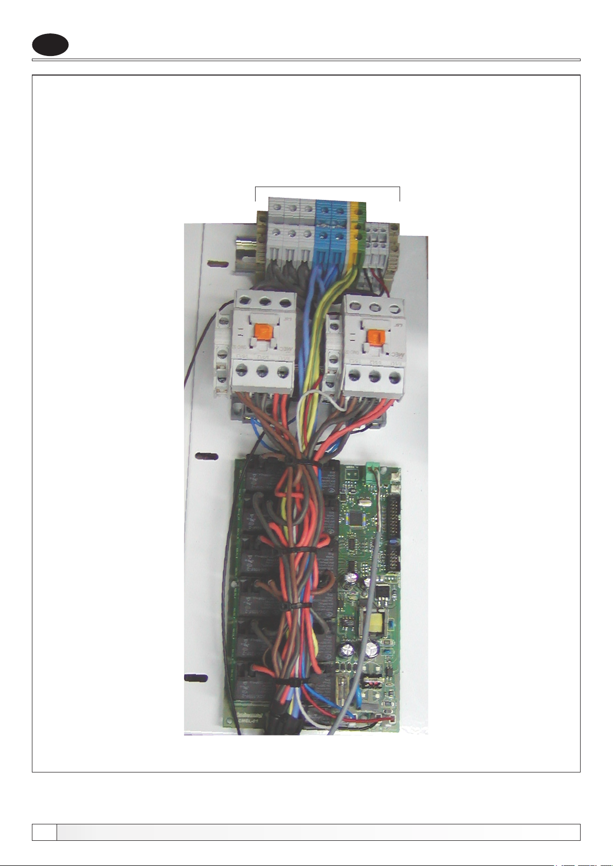
HR
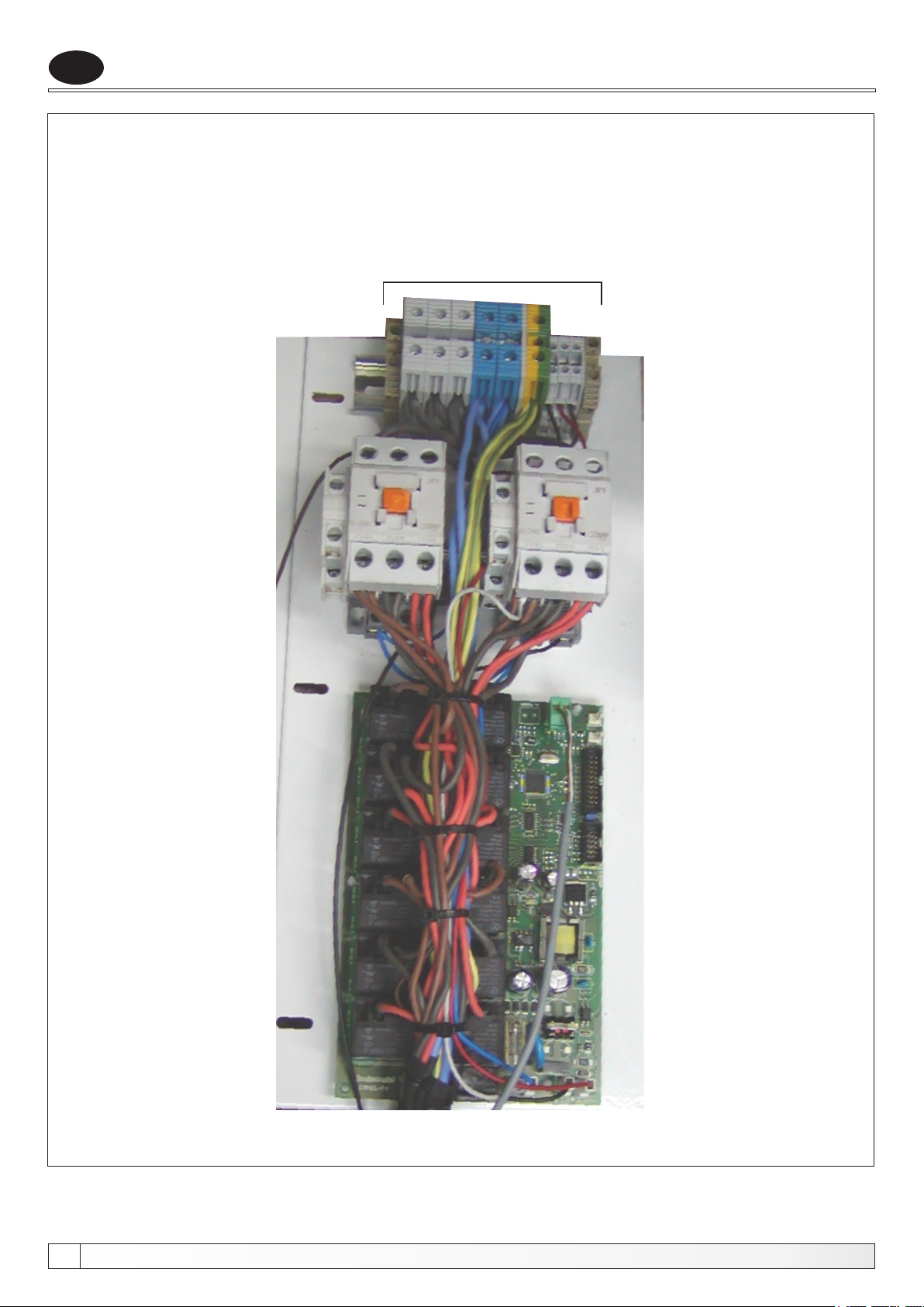
Shema 2. - Prikaz el. pločice elektrokotla
Priključne redne stezaljke
El. pločica
10
Tehničko uputstvo El-Cm
Page 11
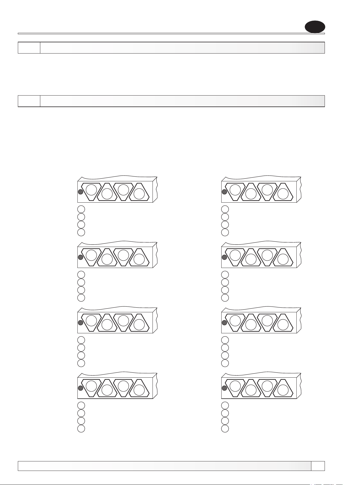
Regulacija, zamjena elektrogrijača
7.0. TEHNIČKI PODACI REGULACIJE
- priključni napon:................................................................................400V / 50Hz
- način upravljanja grijača:.................................................modulirajuća regulacija
- potrošnja elektronike:..........................................................................max 10 VA
- područje regulacije:.................................................................................30-90°C
8.0. ZAMJENA ELEKTRO GRIJAČA
Prije skidanja prednjeg poklopca potrebno je prekinuti dovod električne energije na kotao. Zatim
je potrebno skinuti prednji poklopac i donju stranicu oplate (koji su pričvršćeni vijcima). Prije
skidanja elektro grijača potrebno je isprazniti kotao te odpojiti žice sa elektro grijača. Kod
stavljanja novog elektro grijača potrebno ga je dobro zabrtviti, tako da ne propušta, spojiti žice na
elektro grijač te pričvrstiti donju stranicu oplate i prednji poklopac vijcima na svoje mjesto.
Smještaj elektrogrijača na donjoj strani kotla.
HR
30 kW
36 kW
42 kW
1
1 = 3 x 3.000 W
2 = 3 x 3.000 W
3 = 3 x 3.000 W
4 = 3 x 1.000 W
1
1 = 3 x 3.000 W
2 = 3 x 3.000 W
3 = 3 x 3.000 W
4 = 3 x 3.000 W
1
1 = 3 x 4.000 W
2 = 3 x 4.000 W
3 = 3 x 4.000 W
4 = 3 x 2.000 W
2
2
2
3
3
3
4
4
4
33 kW
39 kW
45 kW
1
1 = 3 x 3.000 W
2 = 3 x 3.000 W
3 = 3 x 3.000 W
4 = 3 x 2.000 W
1
1 = 3 x 4.000 W
2 = 3 x 4.000 W
3 = 3 x 4.000 W
4 = 3 x 1.000 W
1
1 = 3 x 4.000 W
2 = 3 x 4.000 W
3 = 3 x 4.000 W
4 = 3 x 3.000 W
2
2
2
3
3
3
4
4
4
48 kW
Tehničko uputstvo El-Cm
1
1 = 3 x 4.000 W
2 = 3 x 4.000 W
3 = 3 x 4.000 W
4 = 3 x 4.000 W
2
3
4
51 kW
1
1 = 3 x 4.250 W
2 = 3 x 4.250 W
3 = 3 x 4.250 W
4 = 3 x 4.250 W
2
3
4
11
Page 12
HR
9.0. REGULACIJA
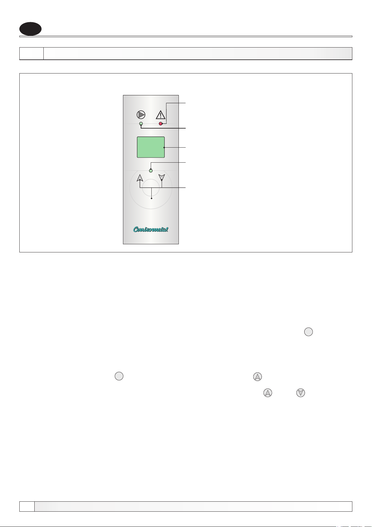
Slika 5. - Digitalna regulacija
Regulacija
Greška (LED-dioda)
Pumpa (LED-dioda)
64
Display
Rad elektrogrijača
(LED-dioda)
Funkcijske tipke
P
Regulacija kotla El-Cm radi tako da mjeri temperaturu i uspoređuje je sa zadanom (željenom)
temperaturom, te na temelju toga traži optimalan raspored snage za zagrijavanje sistema na
željenu temperaturu. Regulator se uključuje/isključuje sobnim termostatom (prekidanjem 230V
napajanja). Ovaj regulator se sam prilagođava sistemu u kojem radi, jer nakon početka rada on
sam traži optimalan raspored snage da bi temperaturu održavao što bliže željenoj, a opet da se
potrošnja energije smanji i da se dobije optimalan omjer. Na komandnoj pločici su display, tipke i
LED diode. Tipke služe za promjenu prikaza na display-u i namještanje promjenjivih parametara u
regulatoru. Display tijekom rada prikazuje mjerenu temperaturu, a pritiskom na tipku P nakon 6
sekundi na display-u se prikazuje programirana željena temperatura.
MOGUĆE PROMJENE PARAMETARA:
Namještanje željene temperature kotla:
Ako se pritisne i drži tipka P , a istovremeno se pritisne strelica gore , na LCD-u će se ispisati
željena temperatura u modu kojem se može mijenjati željena temperatura, što je označeno
točkama pokraj brojeva koje se vide na display-u. Pritiskom tipki gore i dolje mijenja se
vrijednost željene temperature. Nakon što na display-u prikaže željena temperatura, regulator će
zapamtiti namještene parametre te će se nakon nekoliko sekundi sam vratiti u normalan rad i
početi prikazivati mjerenu temperaturu.
Regulacija pamti namještene parametre!
12
Tehničko uputstvo El-Cm
Page 13
Regulacija
Primjer: kotao El-Cm 30 kW
Uvijek nakon uključivanja kotao se zagrijava najvećom snagom dok ne postigne željenu
temperaturu. Kad je postignuta željena temperatura regulator regulira rad kotla raspoređujući
snagu uključenih grijača ovisno o veličini temperature za koju treba zagrijati kotao i to u koracima
30 kW, 22,5 kW, 15 kW, 7,5 kW (MOD1). Ako raspoređivanjem ovih snaga ne može postići željenu
temperaturu regulator prepoznaje da snagu treba povećati, pa prelazi na raspoređivanje snage
po sistemu 30 kW, 22,5 kW, 15 kW (MOD2). Ako ni to nije dovoljno prelazi u rad gdje se samo još
kombiniraju snage od 30 kW i 22,5 kW (MOD3). U krajnjem slučaju prelazi se u MOD4 gdje
elektronika radi još sa snagom 30 kW i nema efekta modulacije odnosno štednje energije, što bi
moglo značiti da je sistem predimenzioniran za ovu snagu grijača.
HR
Tehničko uputstvo El-Cm
13
Page 14
HR
GREŠKE
Moguće su različite greške do kojih može doći tijekom rada.
Ako na display-u piše X (X označava broj 0-5), znači da je došlo do greške pri radu
regulatora, a broj označava uzrok greške:
0 - previsoka je temperatura na senzoru, >90°C.
1 - pogrešna vrijednost na senzoru - vrijednost izvan mjernog područja ili je
senzor temperature pogrešno okrenut.
2 - senzor nije priključen ili regulacija mjeri negativnu temperaturu na senzoru.
3 - pogrešna vrijednost na EEPROM-u (pritisnuti tipku el. grijača što prouzroči
ponovno pokretanje te nakon ponovnog pokretanja greška bi morala biti
otklonjena. Ukoliko se ova greška ponavlja potrebno je kontaktirati
servisera).
4 - tlačna sklopka detektirala je pogrešku, isključuju se grijači.
5 - otvoren je poklopac regulacije - opasnost dodira 400V, pa regulacija
isključuje grijače (nastavak normalnog rada nije moguć prije povratka u
početno stanje).
Greške
NAPOMENA:
- kod svake greške pumpa i dalje nastavlja raditi, no nastavak normalnog rada nije
moguć prije povratka u početno stanje.
Ako bi sustav došao u stanje mirovanja (što je primjećeno u praksi) gdje uključena snaga ne može
zagrijati sustav do željene temperature, no sustav se istovremeno ne hladi (npr. željena
temperatura je 70°C, a na temperaturi od 67°C i uključenoj snazi manjoj od maksimalne, sustav
se postavi u mirovanje gdje temperatura ne pada ali ni ne raste), nakon 10 minuta, sustav
samostalno poveća snagu.
14
Tehničko uputstvo El-Cm
Page 15
Tablica otpora osjetnika
TABLICA OTPORA NTC 5k/25°C OSJETNIKA
HR
(mjerno područje - 20 to + 130 °C)
Temperatura (°C)
-20
-15
-10
-5
0
5
10
15
20
25
30
35
40
45
50
55
Otpor (Ω)
48.535
36.465
27.665
21.158
16.325
12.694
9.950
7.854
6.245
5.000
4.028
3.266
2.663
2.184
1.801
1.493
60
65
70
75
80
85
90
95
100
105
110
115
120
125
130
1.244
1.041
876
740,7
629,0
536,2
458,8
394,3
340,0
294,3
255,6
222,7
190,7
170,8
150,5
Tehničko uputstvo El-Cm
15
Page 16
EN
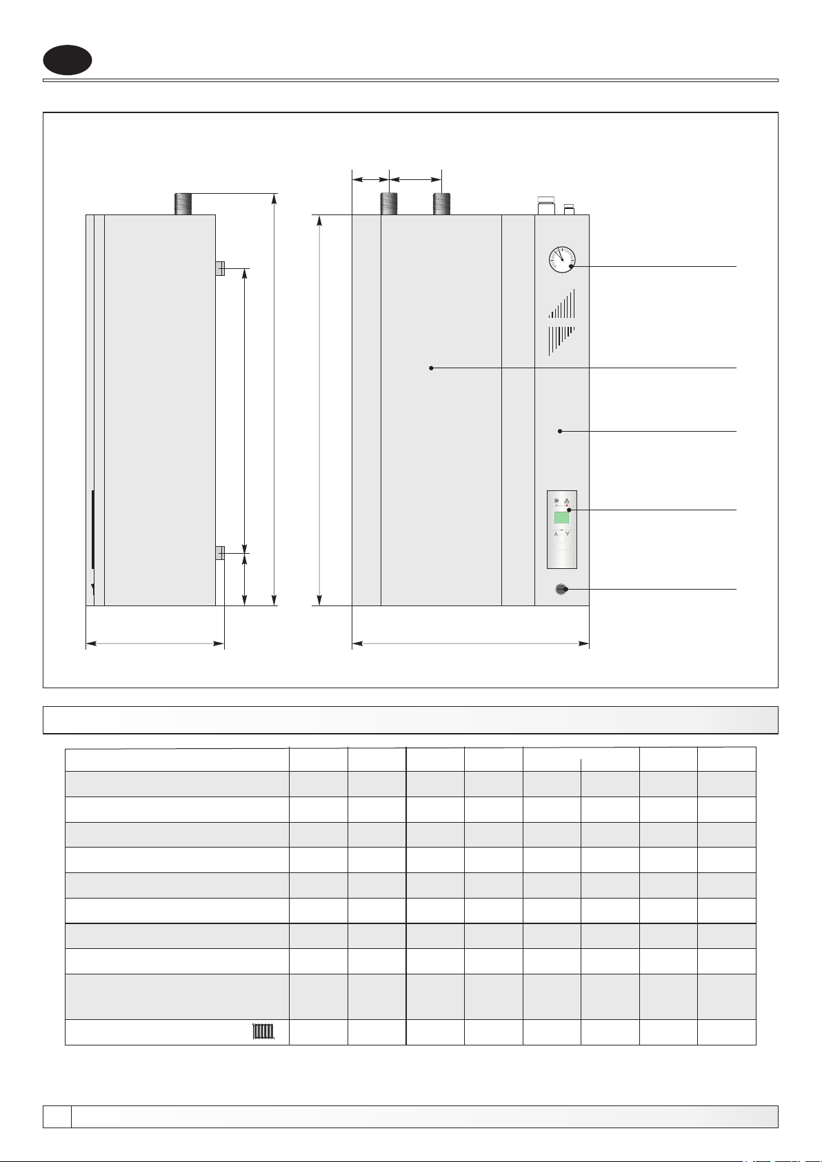
Picture 1. - Basic technical dimensions of the electrical boiler El-Cm
15585
2
3
1
0
4
bar
El-Cm
Technical data
Manometer
Front cover
205
TECHNICAL DATA
El-Cm
Nom. thermal output
Capacity
Electric boiler mass
Max. operating press.
Max. operating press.
Electric heater
Conductor thickness
935
735
115
(kW)
(lit.)
(kg)
(bar)
(MPa)
(kW)
2
(mm )
910
30
22
44
2,5
0,25
3x9+3
5x10
33
33
22
44
2,5
0,25
3x9+6
5x10
64
P
1
0
630
36 4239 45
36
22
44
2,5
0,25
4x9
5x16
39
22
45
2,5
0,25
3x12+3
5x16
42
22
45
2,5
0,25
3x12+6
5x25
0,25
3x12+9
5x25
Console of the
regulation
Digital modulating
regulation
Main switch
45
22
45
2,5
4830
48
22
45
2,5
0,25
4x12
5x25
51
51
22
45
2,5
0,25
4x12,75
5x25
Inlet/Outlet
The boiler resistance
value on water side
Energy efficiency class
16
(R)
6/4"
6/4"
6/4"
6/4"
6/4"
6/4"
6/4"
8(mbar) 9 12,5 15 17,5 19 23 25
C C
C
C C C
Technical manual El-Cm
C C
6/4"
Page 17
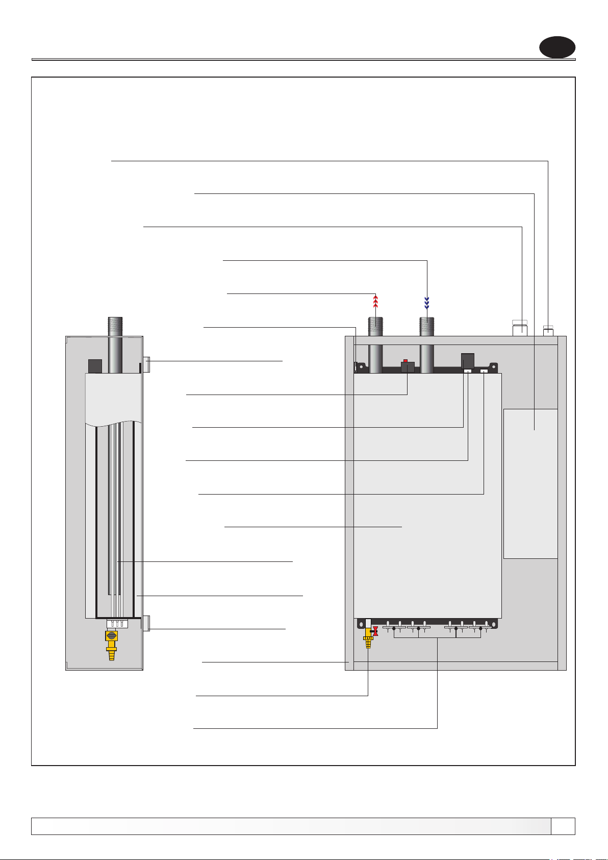
Essential parts
Picture 2. - Essential parts of the electric boiler El-Cm
Wire introducer (pump, room thermostat)
Regulation box
Wire introducer (power supply)
Outlet
Inlet
Microswitch
EN
Boiler porter
Safety thermostat
Pressure switch
Manometer probe
Sensor probe
Boiler
Electric heater
Thermal insulation
Boiler porter
Technical manual El-Cm
Boiler casing
Filling/Draining
Electric heaters
17
Page 18
EN
Boiler description
1.0. INTRODUCTION
Hot water electric boiler El-Cm has a modern design and is constructed out of certified high quality materials by
applying most modern robot welding technology, it is certified according to domestic and international norms and is
therefore suitable for connection to central heating system installation.
We suggest you to follow carefully all instructions of this manual, in order Your electric boiler could operate properly
for a long time.
We do not take the responsibility for eventual printing errors in this manual. In any case we have the right to change
instructions for use of its own products if necessary and useful.
2.0. PURPOSE
The El-Cm electric boilers series is engineered and produced for heating of houses or flats with a nominal thermal
output of 30 to 51 kW as an independent energy source. Their modern design and minimal dimensions enable us to
put them on various places of our house or flat.
3.0. INTEGRAL PARTS OF THE ELECTRIC BOILER El-Cm Compact
BOILER
Is made of high quality steel sheet, welded by applying most modern robot welding technology and certified under the
pressure of 6 bar. Surface is coated by high quality basic colour.
MAIN SWITCH
The purpose of the main switch is to turn on and off the electric boiler power supply.
FRONT COVER
The front cover is attached to the boiler casing with 4 screw (2 piece on the upper and 2 pieces on the lower part of the
electric boiler). By removing the front cover You are enable to approach to the main parts of the electric boiler and the
micro switch are activated. Micro switch turn off the operation of the regulation, but the power supply to the boiler is
not disconnect.
INLET
The inlet tube (6/4”) is marked by the red coloured sticker and is placed on the upper left side of the electric boiler.
18
Technical manual El-Cm
Page 19
Boiler parts
OUTLET
The outlet tube (6/4”) is marked by the blue coloured sticker and is placed on the upper right side of the electric boiler. It
is inserted through the whole length of the electric boiler till its deepest point in order to spread the cooled water inside
the electric boilers body and over the electric heater/heaters.
SENSOR PROBE
On the upper side of the electric boiler is placed sensor probe of the boiler regulation.
SAFETY THERMOSTAT
Overlie security thermostat is situated on the upper side of the boiler, by the pressure switch, when it is activated it turn
off the boiler power supply.
ELECTRIC HEATERS
Electric heaters are situated on the lower part of the electric boiler. Their capacity depends on the total maximal capacity
of the electric boiler.
THERMAL INSULATION
The electric boiler is insulated with mineral wool insulation coating, thickness is 30 mm and is placed on the aluminiumfoil, which prevents losses of heat through convection and radiation.
FILLING - DRAINING / SAFETY VALVE
On the lower part of the electric boiler there is a sealed filling-draining cock for the boiler and the whole system.
PRESSURE SWITCH
In case of pressure loss, the pressure switch turns off the boiler regulation to prevent the operating of the electric boiler
without water, but the power supply to the boiler is not disconnect.
EN
MICRO SWITCH
In case the cover of the electric boiler has been opened, micro switch turn off the operation of the boiler regulation, but
the power supply to the boiler is not disconnect.
BOILER REGULATION
The boiler regulation steers the electric heaters and pump operation and is situated on the console of the boiler
regulation on the right side of the electric boiler.
Technical manual El-Cm
19
Page 20
EN
Installation of electric boiler
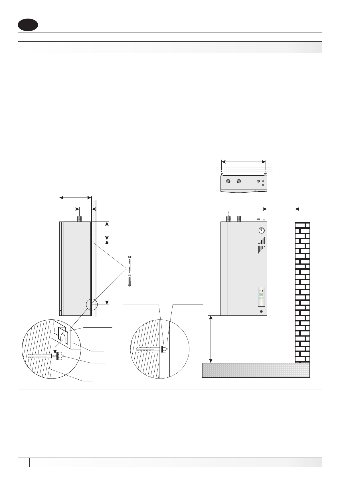
4.0. INSTALLATION OF ELECTRIC BOILER
The El-Cm electric boiler is aimed to be hanged on the wall. For the easier setting on the wall, there is a hanging
console on its back part which is to be hanged on wall metal dowels of M10 type or even stronger. Electric boiler has to
be hanged on the height of min. 0,6 m from the floor, because of the eventual electric heater exchange. The distance
of the side wall has to be min 0,3 m, in order to easier the approach to the boiler. The electric boiler has to be
positioned on the lowest point of the whole installation. If there is a lack of space and therefore the electric boiler has to
be installed on the highest point, an airvent vessel has to be connected on its exit point with a minimum of water
content (cca. 1 lit.). This vessel has to be connected with an airvent pot. We suggest the connection to be executed by
the authorized person.
Picture 3. - Installation of the electric boiler El-Cm on the wall
600
100
205
60
735
Boiler porter
(on the back
side of the
boiler)
Boiler
Screw
After putting the
electric boiler on
the porters,
fasten the
nuts
Boiler porter
(on the back
side of the
boiler)
min. 300 mm
min. 600 mm
1
El-Cm
64
2
3
0
4
bar
P
1
0
20
Wall
Technical manual El-Cm
Page 21
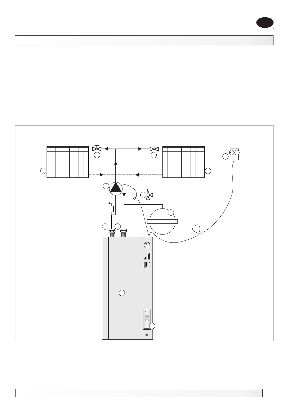
Connecting to the central heating system
5.0. CONNECTING THE El-Cm TO THE CENTRAL HEATING SYSTEM
Connecting to tube installation of the central heating system and the start-up of the electric boiler has to be executed
considering all technical standards and norms, on behalf of the authorized person, who is able to take over the
responsibility.
In a closed heating system it is obligatory to build in a certificated safety valve with opening pressure 0,25 MPa (2.5
bar) and the membran expansion vessel. The safety valve and expansion vessel must be build in according the law
regulation and between the valve or expansion vessel and the boiler may not have any stop elements. Boiler is build
for closed heating system (you can not install this boiler in open heating system).
System pump could be connected on the inline (recommendation) or back line.
Depending of the size of the space, which we would like to be heated, its purpose and heat losses, the proper capacity
of the electric boiler has to be chosen.
Picture 4. - Principle scheme for the connection of the electric boiler
El-Cm to the installation of central heating system
EN
4
3
4
6
3
9
8
7
5
5
2
3
1
0
4
bar
1. Electric boiler El-Cm
El-Cm
2. Digital boiler regulation
3. Radiator
4. Valve
1
5. Removable (holender) connection
6. Room thermostat
Technical manual El-Cm
7. Expansion vessel
64
P
1
0
8. Safety valve (2,5 bar)
2
9. Circulation heating pump
21
Page 22
EN
Electric connection
6.0. CONNECTION TO THE ELECTRICAL POWER NET
All connections to the electrical power net have to be executed in compliance with all norms and standards by an
authorized person. The electric boiler is completely prewired. All additional connections (electric boiler supply,
heating pump, room thermostat) are aimed to be connected through the ordinaly terminal under the front cover of the
electric boiler. Heating pump is amed to connect through ordinaly terminal on regulation on terminal Nr. 3, N and PE.
The electric power supply of the electric boiler is connected by means of an PGP cable with an adequate thickness,
which has to be inserted through the hole on the upper right side of the electric boiler and connected to the terminal
marked with L , L , L , N, PE.
Electric scheme is displayed on the scheme 1.
The instructions shall state that means for disconnection must be incorporated in the fixed wiring in accordance with
the wiring rules.
This appliance is not intended for use by persons (including children) with reduced physical, sensory or mental
capabilities, or lack of experience and knowledge, unless they have been given supervision or instruction concerning
use of the appliance by a person responsible for their safety.
Children should be supervised to ensure that they do not play with the appliance.
Do not switch on if there is a possibility that the water in the heater is frozen.
1 2 3
6.1. SAFETY THERMOSTAT
Safety thermostat is mounted on the upper side of the electric boiler. It disconnect the electric boiler operation if the
boiler temperature achieve 93°C. When we start again the operation of the electric boiler, it is obligatory to wait until
the boiler temperature fail below 70°C, then we take off the boiler cover which is fasten with 4 screws (2 screws on the
upper side and 2 screws on the lower side) and push the red push-button on the safety thermostat. If this failure in the
electric boiler operation happens frequently please call the authorised person for the control.
6.2. CONNECTION OF THE ROOM THERMOSTAT
The electric boilers El-Cm are provided by the ordinaly terminals (1 and 2) for the connection with the room
thermostat. The bridge is prewired on the ordinaly terminal (1 and 2) for the case if the room thermostat is not used. If
we intend to connect it, we should know which kind of room thermostat shall be connected. Simple versions of the
room thermostat are connected serial, inside the steering tension circuit, i.e. to the terminal no. 1. - room thermostat
supply and the antiphase back to the terminal no. 2. More sophisticated room thermostats with a signal light or with an
integrated temperature simulation system, which require to be constantly under tension are to be connected to the
terminals 1 and 2.
22
Technical manual El-Cm
Page 23
Electric scheme
Scheme 1. - Electric scheme of the El-Cm 30 - 51 kW (3-phase connection)
RE
REGULATION
PANEL
Connection
voltage
3x400V
ST
L
1
L
2
L
3
N
P
K
EN
Room
PE
1
thermostat
2
Pump
Ordinaly terminal
3
K
1
EG EG EG EG EG EG
LEGEND:
Technical manual El-Cm
P - main switch
ST - safety thermostat
K - contactor
EG EG EG EG EG
K - contactor 1
1
EG
EG - electric-heater
RE - electronic of regulation
LED-DISPLAY
23
Page 24
EN
Scheme 2. - Electric board of the El-Cm boiler
Ordinaly terminal
Electric board
24
Technical manual El-Cm
Page 25
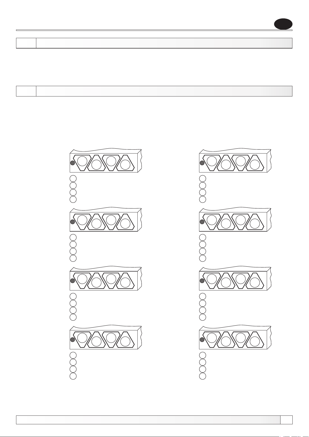
Replacement of the el. heaters
7.0. TECHNICAL DATA
- tension:.............................................................................................400V / 50Hz
- el. boiler steering mode:.....................................................modulating regulation
- electronic part consumption:...............................................................max. 10 VA
- regulation area:........................................................................................20-85°C
8.0. REPLACEMENT OF THE ELECTRIC HEATER
Before You take off the front cover it is necessary to disconnect the power supply. Then we take off the front cover and
lower side of the casing (which are fasten with the screws). Before we take off the electric heater it is necessary to empty
the electric boiler with water and disconnect the wires from the el. heater. When You put on the new electric heater it is
necessary to seal it, connect the wires to the electric heater and attach the lower side of the cover and front cover with the
screws back on the place.
Position of electrical heaters on the bottom side of boiler.
EN
30 kW
36 kW
42 kW
1
1 = 3 x 3.000 W
2 = 3 x 3.000 W
3 = 3 x 3.000 W
4 = 3 x 1.000 W
1
1 = 3 x 3.000 W
2 = 3 x 3.000 W
3 = 3 x 3.000 W
4 = 3 x 3.000 W
1
1 = 3 x 4.000 W
2 = 3 x 4.000 W
3 = 3 x 4.000 W
4 = 3 x 2.000 W
2
2
2
3
3
3
4
4
4
33 kW
39 kW
45 kW
1
1 = 3 x 3.000 W
2 = 3 x 3.000 W
3 = 3 x 3.000 W
4 = 3 x 2.000 W
1
1 = 3 x 4.000 W
2 = 3 x 4.000 W
3 = 3 x 4.000 W
4 = 3 x 1.000 W
1
1 = 3 x 4.000 W
2 = 3 x 4.000 W
3 = 3 x 4.000 W
4 = 3 x 3.000 W
2
2
2
3
3
3
4
4
4
48 kW
Technical manual El-Cm
1
1 = 3 x 4.000 W
2 = 3 x 4.000 W
3 = 3 x 4.000 W
4 = 3 x 4.000 W
2
3
4
51 kW
1
1 = 3 x 4.250 W
2 = 3 x 4.250 W
3 = 3 x 4.250 W
4 = 3 x 4.250 W
2
3
4
25
Page 26
EN
9.0. REGULATION
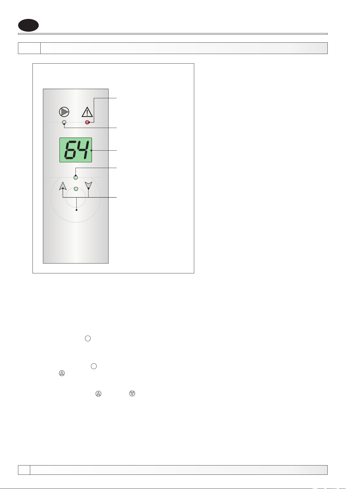
Picture 5. - Digital regulation
Error (LED-diode)
Pump (LED-diode)
Display
Operation of el.
heater (LED-diode)
Regulation
Function button
P
The regulator of the El-Cm measures the temperature and compares it with the set up (desired) temperature. On this
basis it searches for the optimal apportionment of the power used for the system heating to the desired temperature.
The regulator is switched off/on by means of the room thermostat (by turning off the 230V supply). This regulator is self
accommodating to the system in which it is integrated, because immediately after the start-up it finds the optimal
power regime in order to maintain the temperature level as much as possible near to the desired level. In the same
time it reaches the minimum energy consumption, by accomplishing the optimal balance. On the steering board is
visible an display, the buttons and the LED-diode. The buttons are aimed to change displayed values and to choose
adjustable parameters inside the regulator. During the operation, the display shows the measured temperature. By
pressing the button P , after 6 seconds the display shows the set up temperature.
POSSIBLE PARAMETER CHANGES:
Setting the desired electric boiler temperature
By pressing the button P , after the desired temperature level has been displayed and simultaneously pressing the
pointer up , the LCD- display shall show the temperature in the MOD, in which the desired temperature can be
chosen. This is marked by points on the display.
By pressing the button up and down , the desired temperature level can be changed. After the display has shown
the desired temperature, the button should not be pressed any more. After few seconds the regulator shall reestablish
normal functioning and start to display the measured temperature.
The regulation memorize the set up parameters!
26
Technical manual El-Cm
Page 27
Regulation
Example: El-Cm 30 kW
Always after the start-up the electric boiler is warming up intensively, until the desired temperature level has been
reached.
When the desired temperature level has been reached, the regulator steers the operation of the electric boiler
allocating the power of activated heaters depending to the desired temperature to be reached, step by step, i.e. 30
kW, 22,5 kW, 15 kW, 7,5 kW (MOD1). If by allocating of such power levels the desired temperature can not be
reached, the regulator recognizes that the power has to be increased, therefore it reallocates the power as follows: 30
kW, 22,5 kW, 15 kW (MOD 2). If this is not enough the regulator reallocates once again the power in following way:
from 30 kW and 22,5 kW (MOD 3). Leastways, the MOD 4 shall be activated, in which the electronic devices operate
only at 30 kW level, and the modulation or the energy saving operation does not function. This could mean that the
whole system is oversized for the heater's capacity.
EN
Technical manual El-Cm
27
Page 28
EN
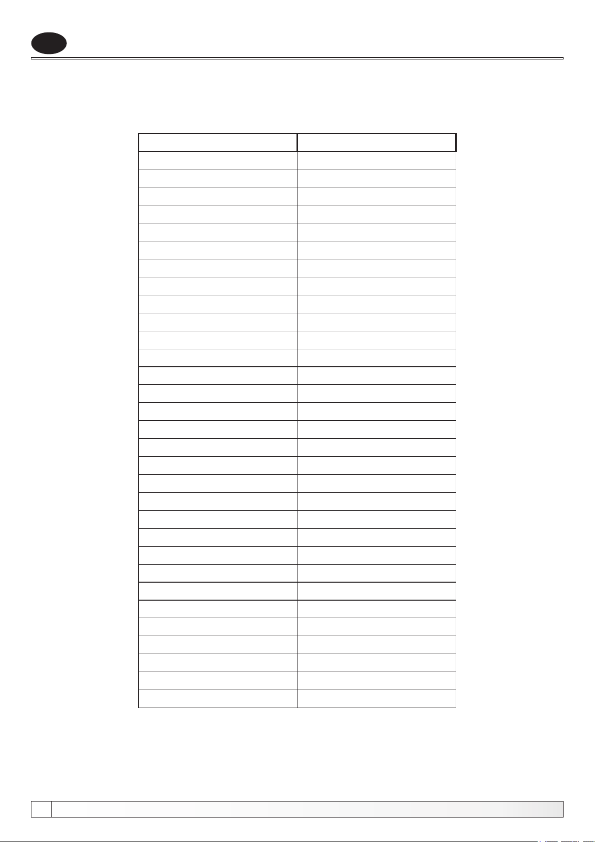
Table of resistance of the boiler sensor
TABLE OF RESISTANCE OF THE NTC 5k/25°C BOILER SENSOR
(measuring field from - 20 to + 130 °C)
Temperature (°C)
-20
-15
-10
-5
0
5
10
15
20
25
30
35
40
45
50
55
Resistance (Ω)
48.535
36.465
27.665
21.158
16.325
12.694
9.950
7.854
6.245
5.000
4.028
3.266
2.663
2.184
1.801
1.493
60
65
70
75
80
85
90
95
100
105
110
115
120
125
130
1.244
1.041
876
740,7
629,0
536,2
458,8
394,3
340,0
294,3
255,6
222,7
190,7
170,8
150,5
28
Technical manual El-Cm
Page 29
Errors
ERRORS
During the operation of the device some errors could appear.
If the display shows X (X stays for the number 0-5), it means that there is a regulator operation error. The
number shows its reason.
0 - too high temperature on the sensor > 90°C
1 - wrong value on the sensor the value is out of the measuring field (>99°C)
or the temperature sensor is wrong connected.
2 - sensor is not connected or the regulation measures the temperature which
is lower then -40°C in the boiler.
4 - the pressure detected an error, electric heaters switch off switch and
the pump still works for 30 sek.
5 - the cover of the regulation is opened dangerous contact with 400V
tension. Therefore the regulation switches off the heaters and the pump
(continuation of the normal functioning possible after setting the originary
operating mode. If this error repeatedly appears, the authorized person
should check the device.
If the systems falls into some kind of stand by (which practically occurs), when the installed power is not enough to
bring the system exactly on the desired temperature level, whereat the system is not cooling down (for example the
desired temperature is 70°C and at the temperature level of 67°C with activated power lower then maximal, the
system reaches the stand by, which means the temperature level remains invariable), after about 10 minutes the
system shall increase the power by itself.
EN
Technical manual El-Cm
29
Page 30
Tvrtka Centrometal d.o.o. ne preuzima odgovornost za moguće netočnosti u ovoj knjižici nastale tiskarskim greškama ili prepisivanjem, sve su slike i sheme načelne te je potrebno svaku prilagoditi stvarnom stanju
na terenu, u svakom slučaju tvrtka si pridržava pravo unositi vlastitim proizvodima one izmjene koje smatra potrebnim.
Centrometal d.o.o. shall not be responsible for possible incorrect data caused by printing errors or error made in transcription and all figures and diagrams are for explanatory purposes only and relevant adjustment
have to be made at the spot. In any case, it reserves the right to modify its products as deemed to be required and useful without any prior notification.
Centrometal d.o.o. Glavna 12, 40306 Macinec, Croatia
central tel: +385 40 372 600, fax: +385 40 372 611
www.centrometal.hr
e-mail: [email protected]
HEATING TECHNIQUE
 Loading...